WO2017110652A1 - 歩行型除雪機 - Google Patents
歩行型除雪機 Download PDFInfo
- Publication number
- WO2017110652A1 WO2017110652A1 PCT/JP2016/087417 JP2016087417W WO2017110652A1 WO 2017110652 A1 WO2017110652 A1 WO 2017110652A1 JP 2016087417 W JP2016087417 W JP 2016087417W WO 2017110652 A1 WO2017110652 A1 WO 2017110652A1
- Authority
- WO
- WIPO (PCT)
- Prior art keywords
- supported
- support frame
- traveling
- machine body
- traveling machine
- Prior art date
- Legal status (The legal status is an assumption and is not a legal conclusion. Google has not performed a legal analysis and makes no representation as to the accuracy of the status listed.)
- Ceased
Links
Images






Classifications
-
- E—FIXED CONSTRUCTIONS
- E01—CONSTRUCTION OF ROADS, RAILWAYS, OR BRIDGES
- E01H—STREET CLEANING; CLEANING OF PERMANENT WAYS; CLEANING BEACHES; DISPERSING OR PREVENTING FOG IN GENERAL CLEANING STREET OR RAILWAY FURNITURE OR TUNNEL WALLS
- E01H5/00—Removing snow or ice from roads or like surfaces; Grading or roughening snow or ice
- E01H5/04—Apparatus propelled by animal or engine power; Apparatus propelled by hand with driven dislodging or conveying levelling elements, conveying pneumatically for the dislodged material
Definitions
- the present invention relates to a walking snowplow.
- the rear part of the vehicle body frame is mounted on the traveling frame so as to swing up and down.
- the vehicle body frame includes a snow removal working device and an engine.
- the front part of the vehicle body frame can be swung up and down by the lifting mechanism.
- the height of the snow removal work device can be adjusted by swinging the snow removal work device up and down together with the body frame.
- the machine is swung up and down with respect to the crawler traveling device by the lifting cylinder.
- a snow removal unit is connected to the front of the machine.
- This machine is equipped with an engine that transmits driving force to the snow removal section.
- an operation unit is provided on the machine, and a handle is provided on the operation unit.
- An operation panel is disposed in the operation unit, and an auger housing lifting switch is provided on the operation panel.
- the machine is provided with a bonnet, and a work lamp projects from the bonnet.
- a traveling machine body having a pair of left and right crawler traveling devices, a support frame supported by the traveling machine body so as to be able to swing up and down, a snow removing portion that is supported by the support frame and performs snow removal work in front of the traveling machine body, and supported by the support frame
- a walking type snowplow that includes an engine that outputs a driving force to the snow removal unit and an elevating drive mechanism that swings the support frame
- the walking frame is operated by swinging the support frame up and down by the elevating drive mechanism.
- the snow removal part swings up and down with respect to the airframe, and the height of the snow removal part can be adjusted.
- Patent Document 1 discloses that the snow removal unit and the engine can be driven by the same engine while allowing the snow removal unit and the engine to be integrally swung up and down with respect to the traveling machine body.
- the first object of the present invention is to drive the snow removal unit and the crawler traveling device by the same engine while enabling the integral operation of the snow removal unit and the engine and simplifying the structure of the traveling transmission system.
- Another object of the present invention is to provide a walking type snow remover capable of raising and lowering a snow removal part by a small and lightweight raising and lowering drive mechanism.
- the first problem with respect to the background art [2] is as follows.
- a walking type snowplow comprising a traveling machine body having a pair of left and right crawler traveling devices, a snow removing unit that performs snow removal work in front of the traveling machine body, an engine that outputs driving force to the snow removing unit, and a pair of left and right steering handles.
- the ground clearance of the snow removal part can be adjusted by configuring the snow removal part and the engine so that the traveling machine body can be swung up and down integrally. And it becomes unnecessary to provide the special power transmission structure which enables adjustment of the ground clearance of a snow removal part in the work transmission system which transmits an engine output to a snow removal part.
- Patent Document 1 A similar technique is disclosed in Patent Document 1, but in this type of walking type snowplow, a support frame that is supported so as to be swingable up and down is provided on a traveling machine body, and a snow removal unit and an engine are provided on the support frame. Although supported, the higher the mounting height of the support frame to the traveling machine body, the higher the arrangement height of the engine, and the higher the center of gravity of the snowplow due to the engine weight.
- a second object of the present invention is to provide a walking type snow remover capable of swinging up and down the snow removal part and the engine integrally with the traveling machine body while lowering the height of the center of gravity of the entire snow removal machine.
- a traveling machine body having a pair of left and right crawler traveling devices, a support frame supported by the traveling machine body so as to be able to swing up and down, a snow removing portion that is supported by the support frame and performs snow removal work in front of the traveling machine body, and supported by the support frame
- a walking snowplow equipped with an engine that outputs a driving force to the snow removal unit and a lift drive mechanism that swings the support frame by the drive force of the electric motor
- the support frame is moved up and down by the lift drive mechanism.
- a third object of the present invention is to provide a walking type snow remover that can avoid the above-mentioned problem while the engine swings up and down together with the snow removal portion.
- a traveling machine body a support frame that is supported by the traveling machine body so as to swing up and down, a snow removal part that is supported by the support frame and that removes snow in front of the traveling machine body, and is supported by the support frame and outputs a driving force to the snow removal part.
- the snow removal unit moves up and down with respect to the traveling machine body by swinging the support frame using the lifting drive mechanism. The height of the snow removal part can be adjusted.
- a fourth object of the present invention is to provide a walking type snow remover capable of avoiding the above-described problems while the engine swings up and down together with the snow removal portion.
- a traveling machine body having a pair of left and right crawler traveling devices, a support frame supported by the traveling machine body so as to be swingable up and down, a snow removal unit supported by the support frame and performing snow removal work in front of the traveling machine body,
- An engine that is supported by a support frame and outputs a driving force to the snow removal unit;
- a traveling mission that is supported by the support frame and that distributes and transmits power input from the engine to the left and right crawler traveling devices;
- the left and right crawler traveling devices include a driving wheel body supported rotatably on the front portion of the traveling machine body, a driven wheel body rotatably supported on the traveling machine body behind the driving wheel body, A crawler belt wound around the driving wheel and the driven wheel,
- the support frame is supported so as to be swingable up and down with the rotation axis of the drive wheel body of the left and right crawler travel devices as a swing axis,
- the elevating drive mechanism includes an electric motor
- the snow removal unit swings up and down together with the support frame, and the ground clearance of the snow removal unit can be adjusted.
- the engine swings up and down together with the support frame, but the support frame swings up and down with the rotation axis of the drive wheel of the left and right crawler travel device as the swing axis, and is supported. Since the traveling mission swings up and down together with the frame, it is not necessary to provide a special interchangeable structure that allows the snow removal portion and the engine to swing up and down in the traveling transmission system that transmits the driving force of the engine to the left and right crawler traveling devices.
- the elevating drive mechanism applies the elevating operation force at a position away from the rotation axis of the drive wheel body to the vicinity of the rear part of the crawler belt. Therefore, the elevating drive mechanism is made small and light with an electric motor as a power source.
- the support frame can be smoothly swung up and down by the lift drive mechanism. Therefore, the left and right crawler travel devices can be driven by the engine that drives the snow removal unit while the travel transmission system has a simple structure without any special accommodation structure, and the snow removal unit is adjusted up and down by a small and lightweight lifting drive mechanism. it can.
- the elevating drive mechanism includes a pinion gear driven by the electric motor, and a rack gear engaged with the pinion gear.
- the rotational driving force of the electric motor can be converted into the operating force for swinging the support frame by a simple and lightweight power conversion mechanism including a pinion gear and a rack gear.
- the electric motor and the pinion gear are supported by the support frame, and the rack gear is supported by the traveling machine body.
- the member provided with the rack gear tends to be a long member that is longer in the vertical direction of the traveling machine body than the support member that supports the electric motor and the pinion gear. According to this configuration, when adjusting the height of the snow removal portion, the long member can be prevented from moving, and the elevating drive mechanism can be easily provided.
- the elevating drive mechanism is located behind the engine.
- the support frame is swung against the engine load in order to adjust the lifting and lowering of the snow removal portion, but the support frame has a larger distance than the distance from the swing axis of the support frame to the engine. Since the distance from the swing axis to the lift drive mechanism is longer, the operating force of the lift drive mechanism can be efficiently applied to the swing operation of the support frame.
- the elevating drive mechanism is located behind the rear end of the body frame of the traveling body.
- the distance from the rotating shaft core of the drive wheel body to the lifting drive mechanism can be increased and the operating force of the lifting drive mechanism can be supported compared to the mechanism in which the lifting drive mechanism is located in front of the rear end of the body frame. Efficiently acts on the swinging operation of the frame.
- the elevating drive mechanism and the battery are aligned in the lateral direction of the traveling machine body.
- a traveling machine body having a pair of left and right crawler traveling devices, a support frame supported by the traveling machine body so as to be swingable up and down, a snow removal unit supported by the support frame and performing snow removal work in front of the traveling machine body,
- An engine that is supported by a support frame and that outputs a driving force to the snow removal unit; and an elevating drive mechanism that swings the support frame.
- the body frame of the traveling body includes a pair of left and right traveling frame bodies that support the left and right crawler traveling devices, and a laterally connecting frame portion that connects the rear portions of the left and right track frame sections.
- the support frame is supported by the left and right track frame portions in a state of being swingable up and down while being positioned between the left and right track frame portions,
- a pair of left and right steering handles are extended from the left and right end portions of the connecting frame portion.
- the support frame supporting the snow removal unit and the engine is operated to swing up and down with respect to the track frame unit.
- the airframe includes a left and right track frame portion and a connecting frame portion, and a pair of left and right control handles extend from the connecting frame portion, so that an empty space can be obtained between the left and right track frame portions in the airframe frame. Since the support frame is positioned between the left and right track frame parts so as to be swingable up and down, the support frame is inserted into an empty space of the body frame and moved to the traveling frame of the support frame. The installation height can be lowered. Since the mounting height of the support frame can be lowered, the arrangement height of the engine can be lowered.
- the steering handle is supported by the connecting frame part of the fuselage frame that supports the support frame so that it can swing up and down, the attitude of the steering handle does not change even if the height of the snow removal part is adjusted. Regardless of the height adjustment, the grip of the steering wheel does not change. Therefore, while the work transmission system that transmits the engine output to the snow removal part can adjust the height of the snow removal part without providing a special interchangeable structure that enables the snow removal part to adjust the ground height, Since the arrangement height can be lowered, the height of the center of gravity of the entire snowplow can be lowered and the walking type snowplow can be driven stably.
- the body frame includes a handle support frame portion protruding upward from left and right ends of the connection frame portion, and the left and right steering handles are supported by the handle support frame portion. This is supported by the connecting frame portion.
- a wide connecting surface for connecting the steering handle can be provided on the connecting frame portion by the handle support frame portion, and the steering handle can be firmly supported.
- the left and right handle support frame portions are configured by plate-like members whose plate thickness direction is the lateral width direction of the traveling vehicle body, and the left and right steering handles are disposed on the laterally outer sides of the handle support frame portion. Supported on the side.
- the steering handle can be firmly supported on the side surface of the handle support frame portion while widening the interval between the left and right handle support frame portions to make it easy to use the space between the left and right handle support frame portions for deployment of a battery or the like.
- the left and right steering handles are made of round pipe material,
- the base portions supported by the handle support frame portions of the left and right steering handles are pressed and deformed so that a part of the outer peripheral surface is a flat surface along the side surface of the handle support frame portion.
- the steering handle can be firmly connected to the handle support frame portion by configuring the flat handle surface along the side surface of the handle support frame portion while firmly constructing the steering handle from the round pipe material.
- the vehicle includes a traveling mission that is supported by the support frame and that distributes and transmits power input from the engine to the left and right crawler traveling devices, and the left and right crawler traveling devices include the track frame unit.
- a driving wheel body rotatably supported on the front portion of the driving wheel body, a driven wheel body rotatably supported on the track frame portion behind the driving wheel body, the driving wheel body and the driven wheel body,
- the support frame is supported so as to be able to swing up and down with the rotation axis of the drive wheel body of the left and right crawler travel devices as a swing axis.
- the traveling mission can be swung vertically with respect to the traveling machine body integrally with the engine without providing a special accommodation structure in the traveling transmission system that transmits the output of the engine to the left and right crawler traveling devices. . That is, the height of the snow removal part to the ground can be adjusted while the traveling transmission system has a simple structure without a special accommodation structure.
- a traveling machine body having a pair of left and right crawler traveling devices, a support frame supported by the traveling machine body so as to be swingable up and down, a snow removal unit supported by the support frame and performing snow removal work in front of the traveling machine body,
- An engine that is supported by a support frame and outputs a driving force to the snow removal unit; and an elevating drive mechanism that swings the support frame by a driving force of an electric motor
- a steering handle is supported on the traveling body, The steering handle is provided with a grip portion facing the front and rear of the traveling aircraft, An elevating operation switch for operating the electric motor is supported by the steering handle in a state where a finger operation of a hand supporting the grip portion of the traveling body lateral inner side of the grip portion is located. Yes.
- the support frame swings up and down with respect to the traveling machine body. Since the posture does not change, the postures of the steering handle and the lifting operation switch do not change. Therefore, even if the height of the snow removal portion with respect to the ground is adjusted, the degree to which the steering wheel is held does not change, and the steering feeling is unlikely to change. Also, since the attitude of the steering handle and the attitude of the lifting / lowering operation switch do not change, the operating condition of the lifting / lowering operation switch is difficult to change, and it is easy to adjust the snow removal part with high accuracy regardless of the change in the height of the snow removal part to the ground. It is possible to maintain a state where it is easy to work.
- the steering handle is provided at a position ahead of the grip portion, includes a boss portion that supports a clutch lever, includes a support member that extends rearward from the boss portion, and moves up and down.
- the operation switch is supported by the steering handle by being supported by the support member.
- the lifting operation switch can be supported on the steering handle with a simple mounting structure in which the boss portion for the clutch lever is used as the mounting portion of the support member.
- the vehicle is provided with a traveling mission that is supported by the support frame and distributes and transmits power input from the engine to the left and right crawler traveling devices.
- a driving wheel body supported rotatably at the front part, a driven wheel body supported rotatably by the traveling machine body behind the driving wheel body, and the driving wheel body and the driven wheel body
- the support frame is supported so as to be swingable up and down with the rotation axis of the drive wheel body of the left and right crawler travel devices as a swing axis.
- the ground clearance of the snow removal section can be adjusted without providing a special interchangeable structure for enabling the ground clearance of the snow removal section to be adjusted in the traveling transmission system that transmits the driving force from the engine to the crawler traveling device. it can.
- a traveling machine body a support frame supported by the traveling machine body so as to be swingable up and down, a snow removal part supported by the support frame and performing snow removal work in front of the traveling machine body, supported by the support frame, and the snow removal part And an elevating drive mechanism for swinging the support frame.
- a steering handle and a headlamp are supported by the traveling body.
- the support frame swings up and down with respect to the traveling machine body. It does not change, neither the headlight posture nor the steering handle posture. Therefore, even if the height of the snow removal part is adjusted, the lighting condition by the headlamps does not change and it is easy to see the front, and the steering handle does not change so Since it is difficult to change, it is easy to maintain a state where it is easy to perform snow removal work regardless of a change in the height of the snow removal part to the ground.
- the headlamp is supported by the traveling body by being supported by the steering handle.
- the mounting position of the headlamp can be raised with a simple support structure in which the steering handle is used as a column member of the headlamp.
- the snow removal unit includes an auger that collects snow and a shooter that discharges the snow collected by the auger by a blower, and the headlamp is in a lateral direction of the traveling body with respect to the shooter. Is misaligned.
- the traveling machine body includes a driving wheel body supported to be drivable at a front portion of the traveling machine body, and a driven wheel body rotatably supported to the traveling machine body behind the driving wheel body. And a crawler belt wound around the drive wheel body and the driven wheel body, and the support frame is supported so as to be swingable up and down with the rotation shaft core of the drive wheel body as a rocking shaft core. Yes.
- the driving wheel body is located in front of the driven wheel body, so that the rocking radius of the snow removal portion is smaller than when the rotational axis of the driven wheel body is the rocking shaft core of the support frame.
- the height of the snow removal part can be adjusted. That is, when the crawler belt is driven by an engine that transmits driving force to the snow removal portion, the crawler belt can be driven while the swing radius of the snow removal portion is reduced.
- FIG. 12 is a side view showing the interlocking mechanism having another embodiment structure in a state where the steering lever is operated near the stroke end on the grip side.
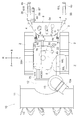
- FIG. 1 is a side view showing an entire walking snowplow according to an embodiment of the present invention.
- FIG. 2 is a plan view showing the entirety of the walking type snowplow according to the embodiment of the present invention.
- the direction [F] shown in FIGS. 1 and 2 is the “front side” of the traveling aircraft body
- the direction [B] is the rear side of the traveling aircraft body
- the direction [L] is the “left side” of the traveling aircraft body
- the direction [R] is It is defined as the “right side” of the traveling aircraft.
- the walking type snowplow includes a traveling machine body 3 in which a pair of left and right crawler traveling devices 2 are mounted on a body frame 1.
- the traveling machine body 3 includes a pair of left and right steering handles 4 provided at the rear, and is configured to be a walking type so that the traveling machine body 3 can be run and steered while walking behind the traveling machine body 3.
- a snow removal unit 10 is disposed in front of the traveling machine body 3.
- An engine 5 is disposed above the traveling machine body 3 behind the snow removal unit 10.
- the walking type snowplow can perform snow removal work by the snow removal unit 10 by running the traveling machine body 3.
- the snow removal unit 10 includes an auger housing 11 and a blower case 12 connected to the rear part of the auger housing 11.
- An auger 13 is supported on the auger housing 11 so as to be driven to rotate.
- a blower 14 is mounted in the blower case 12 so as to be driven to rotate.
- a shooter 15 protrudes upward from the blower case 12.
- the auger 13 collects snow and the shooter 15 discharges the snow collected by the blower 14 from the discharge port 15a by the jet power of the blower 14.
- the body frame 1 includes a pair of left and right traveling frame body front and rear track frame portions 20 and a traveling frame body side connection frame portion 21.
- the connecting frame portion 21 connects the rear portions of the left and right track frame portions 20.
- the longitudinal cross-sectional shape of the connection frame part 21 is a groove shape opened forward.
- the plane view shape of the body frame 1 is a U-shape opened forward.
- the body frame 1 includes an empty space in which a traveling mission 30 and a support frame 75 described later are placed.
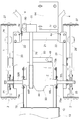
- the left and right crawler traveling devices 2 are distributed and supported by the left and right track frame portions 20 as shown in FIG.
- the left and right crawler travel devices 2 are configured such that the driving wheel body 25 is drivably supported by the front end portion of the track frame portion 20, and is positioned behind the driving wheel body 25.
- a driven wheel body 26 rotatably supported by the frame portion 20 and a crawler belt 27 wound around the drive wheel body 25 and the driven wheel body 26 are provided.
- a slip-off preventing member 28 is engaged with the crawler belt 27 between the driving wheel body 25 and the driven wheel body 26.
- the come-off prevention member 28 is supported by the track frame portion 20.
- the pair of left and right steering handles 4 are extended upward and rearward from the left and right ends of the connecting frame portion 21 as shown in FIGS.
- handle support frame portions 22 are provided at the left and right ends of the connecting frame portion 21.
- the left and right handle support frame portions 22 project upward from the connection frame portion 21.
- a base portion 4 a of the steering handle 4 is supported on the handle support frame portion 22.
- the left and right handle support frame portions 22 are constituted by plate-like members.
- the plate-like member is attached to the connecting frame portion 21 in an attachment posture in which the plate thickness direction is the traveling body lateral width direction.
- the base portions 4 a of the left and right steering handles 4 are supported on the side surfaces of the handle support frame portion 22 on the lateral outer side.
- the left and right steering handles 4 are constituted by round pipe members.
- the base 4a of the left and right steering handles 4 is subjected to a press deformation process in a state where a part of the outer peripheral surface is a flat surface.
- the base portion 4 a is connected to the handle support frame portion 22 with a flat surface along the side surface of the handle support frame portion 22.
- the base portion 4a and the handle support frame portion 22 are connected by a connecting bolt.
- the connecting means between the base portion 4a and the handle support frame portion 22 is not limited to the connecting bolt, and welding may be employed.
- the grip 4b is provided at the extended end of the left and right steering handles 4.
- the grip portions 4 b of the left and right steering handles 4 extend in the front-rear direction of the traveling machine body 3.
- a portion between the grip portion 4 b and the base portion 4 a of the left and right steering handles 4 is connected by a pair of reinforcing rods 6 and 7.
- the pair of reinforcing rods 6 and 7 are arranged at intervals in the vertical direction (longitudinal direction) of the steering handle 4.
- the left and right steering handles 4 are reinforced by supporting each other by connecting with the reinforcing rods 6 and 7.
- An operation panel 8 is supported on the upper reinforcing bar 6.
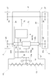
- the left and right crawler travel devices 2 and the snow removal unit 10 are driven by the driving force transmitted from the engine 5 based on the power transmission structure shown in FIG.
- a travel clutch 31 is provided across the output shaft 5 a and the input shaft 30 a of the travel mission 30.
- the traveling clutch 31 is constituted by a belt tension clutch.
- the traveling clutch 31 is not limited to a belt tension clutch, and various types of clutches such as a multi-plate friction clutch may be employed.
- the driving wheel bodies 25 of the left and right crawler traveling devices 2 are supported on the left and right output shafts 30L and 30R of the traveling mission 30 so as not to be relatively rotatable.
- the traveling mission 30 is provided with a hydrostatic continuously variable transmission 32 (hereinafter abbreviated as HST32).
- the HST 32 changes the driving force of the input shaft 30a by a variable displacement type axial plunger pump (not shown) and an axial plunger motor (not shown), and the driving force after the shifting is changed to the left and right output shafts 30L, 30R. To communicate.
- the traveling machine body 3 can travel.
- the left and right crawler travel devices 2 are driven to switch between the forward side and the reverse side, and the forward drive speed and the reverse drive speed of the left and right crawler travel devices 2 are steplessly shifted to travel.
- the machine body 3 can be switched between forward and reverse, and can be continuously shifted and moved forward and backward.
- the operating portion (tension pulley) of the traveling clutch 31 and the traveling clutch lever 33 are linked.
- the traveling clutch lever 33 is supported by the left steering handle 4. Specifically, the traveling clutch lever 33 is positioned above the grip portion 4b of the left steering handle 4 so as to be able to swing up and down. By operating the clutch lever 33, the traveling clutch 31 can be switched to the engaged state.
- the traveling clutch lever 33 is configured as a deadman type. That is, the traveling clutch 31 can be maintained in the engaged state by operating the clutch lever 33, and the traveling clutch 31 is disengaged by releasing the operation of the clutch lever 33.
- a shift lever 34 that shifts the HST 32 is provided on the operation panel 8.
- a work clutch 35 is provided across the output shaft 5 a of the engine 5 and the input shaft 10 a of the snow removal unit 10.
- the work clutch 35 is constituted by a belt tension clutch.
- the work clutch 35 is not limited to a belt tension clutch, and various types of clutches such as a multi-plate friction clutch may be employed.
- the operating portion (tension pulley) of the work clutch 35 and the work clutch lever 36 are linked.
- the working clutch lever 36 is supported by the right steering handle 4. Specifically, the clutch lever 36 is positioned above the grip portion 4b of the right steering handle 4 so as to be vertically swingable. By operating the clutch lever 36, the operation clutch 35 can be switched to the engaged state.
- the traveling mission 30 is provided with a pair of left and right steering clutches 37L and 37R and a pair of left and right steering brakes 38L and 38R.
- the left and right steering clutches 37L and 37R include clutch ring bodies 39L and 39R.
- Clutch ring bodies 39L and 39R are fitted to the outer peripheral portions of the spline portions of output shafts 30L and 30R so as to be slidable and relatively non-rotatable.
- Claw clutch mechanisms 41L and 41R are provided across the clutch ring bodies 39L and 39R and the output gear 40.
- the output gear 40 is supported by the left and right output shafts 30L and 30R in a state in which the output gear 40 can be opposed to the left and right output shafts 30L and 30R.
- the output gear 40 is driven by the output of the HST 32.
- Shifters 42L and 42R are engaged with clutch ring bodies 39L and 39R.
- the left and right shifters 42L and 42R are swingably supported by the transmission case 44 (see FIG. 9) via the rotation support shafts 43L and 43R.
- the operation arms 45L and 45R are supported by the left and right rotation support shafts 43L and 43R so as not to be relatively rotatable.
- the left and right steering clutches 37L and 37R are engaged when the claw clutch mechanisms 41L and 41R are operated to be engaged, and are engaged when the claw clutch mechanisms 41L and 41R are operated to be disconnected. Become.
- the left and right steering clutches 37L and 37R are operated in an engaged state, thereby interlockingly connecting the output gear 40 and the output shafts 30L and 30R to transmit the output of the HST 32 to the driving wheel body 25.
- the left and right steering clutches 37L and 37R release the interlocking connection between the output gear 40 and the output shafts 30L and 30R when the pawl clutch mechanisms 41L and 41R are operated in the disengaged state, and the crawler travel device 2 from the HST 32 is released. Cut off power transmission to.
- Left and right steering brake 38L. 38R is constituted by a multi-plate friction clutch.
- the shifters 42L, 42R are swung by the swinging operation of the operating arms 45L, 45R, so that the clutch wheels 39L, 39R are attached to the clutch.
- the steering brakes 38L and 38R are operated against the force spring 46, or are moved away from the steering brakes 38L and 38R.
- the left and right steering brakes 38L and 38R are turned on by being pressed by the operation portions 39a and 39b of the clutch ring bodies 39L and 39R that are operated to be shifted, and the operation portions are operated by releasing the clutch ring bodies 39L and 39R. It will be in a cutting state by releasing the press by 39a, 39b.
- the left and right steering brakes 38L and 38R When the left and right steering brakes 38L and 38R are in the engaged state, the left and right steering brakes 38L and 38R apply friction braking force to the output shafts 30L and 30R, and brake the crawler traveling device 2.
- the left and right steering brakes 38L and 38R strengthen the brake applied to the crawler traveling device 2 as the pressing force of the clutch wheel 39L39R is increased.
- the left and right steering brakes 38L and 38R are turned off, the friction braking force applied to the output shafts 30L and 30R is released, and the brake applied to the crawler traveling device 2 is released.
- one actuator 49 is linked to the left and right operation arms 45 ⁇ / b> L and 45 ⁇ / b> R via a linkage mechanism 50.
- the left and right steering clutches 37L and 37R and the left and right steering brakes 38L and 38R can be operated by one actuator 49.
- an electric motor is employed as the actuator 49.
- the actuator 49 is not limited to an electric motor, and various power sources such as a cylinder may be employed. Hereinafter, the actuator 49 will be described as an electric motor 49.
- the linkage mechanism 50 includes a seesaw member 51 as shown in FIG.
- the seesaw member 51 is supported by the mission case 44 via a support shaft 52.
- the seesaw member 51 can be oscillated with the axis of the support shaft 52 as the oscillating axis.
- the left and right end portions of the seesaw member 51 are connected to the left and right operation arms 45L and 45R by a pair of left and right interlocking links 53L and 53R.
- End portions 54L and 54R on the seesaw member side of the left and right interlocking links 53L and 53R are slidably engaged with elongated connection holes 55L and 55R of the seesaw member 51, respectively.
- the seesaw member 51 and the electric motor 49 are linked to each other via a sector gear 56, a small diameter gear 57, a large diameter gear 58, and a worm gear 59.
- the sector gear 56 is provided with a connecting arm portion 56a. Since the support shaft 52 and the connecting pin 56b are mounted across the connecting arm portion 56a and the seesaw member 51, the sector gear 56 and the seesaw member 51 are connected so as not to be relatively rotatable.
- the sector gear 56 and the small diameter gear 57 are engaged with each other.
- the small-diameter gear 57 and the large-diameter gear 58 are interlocked and connected via the rotation support shaft 60.
- the large diameter gear 58 and the worm gear 59 are engaged with each other.
- the worm gear 59 is attached to the output shaft 49 a of the electric motor 49 so as not to be relatively rotatable.
- the seesaw member 51 When the electric motor 49 is operated in the neutral state, the seesaw member 51 is in the neutral position [N].
- the end portions 54L and 54R of the left and right interlocking links 53L and 53R are positioned at the arm side end portions of the connection holes 55L and 55R, and the left and right operation arms 45L and 45R are operated to the clutch engagement position by the return spring 47. Yes. That is, the left and right steering clutches 37L and 37R are in the engaged state.
- the seesaw member 51 When the electric motor 49 is operated from the neutral state to the left turn side, the seesaw member 51 is swung in the left turn direction [LS] from the neutral position [N], and the left interlocking link 53L is pulled by the seesaw member 51. Then, the left operation arm 45L is swung from the clutch engagement position toward the brake engagement position, and the left steering clutch 37L is switched to the disengaged state.
- the seesaw member 51 is further swung in the left turning direction [LS] after the left steering clutch 37L is turned off, the left operating arm 45L is operated to the brake position, and the left steering brake 38L enters the on state.
- the seesaw member 51 When the electric motor 49 is operated from the neutral state to the right turn side, the seesaw member 51 is swung in the right turn direction [RS] from the neutral position [N], and the right interlocking link 53R is moved by the seesaw member 51.
- the right operation arm 45R When the pulling operation is performed, the right operation arm 45R is swung from the clutch engagement position toward the brake engagement position, and the right steering clutch 37R is switched to the disengaged state.
- the seesaw member 51 When the seesaw member 51 is further swung in the right turning direction [RS] after the right steering clutch 37R is in the disengaged state, the right operating arm 45R is operated to the brake position, and the right steering is performed.
- the brake 38R is engaged.
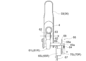
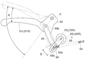
- a pair of left and right steering levers 61 ⁇ / b> L and 61 ⁇ / b> R are distributed and supported by the left and right steering handles 4.
- a pair of left and right brackets 62 project downward from a portion in front of the grip portion 4 b of the steering handle 4.
- the bracket 62 and the bases of the steering levers 61L and 61R are connected via a support shaft 63.
- the steering levers 61 ⁇ / b> L and 61 ⁇ / b> R are lifted and swung with the shaft 63 of the support shaft 63 as the swing shaft X when operated.
- the steering levers 61L and 61R swing downward by the operating force of the return spring 64 by releasing the grip operation.
- the return spring 64 is connected to an interlocking member 69 described later.
- the left operation position detection sensor 65 ⁇ / b> L is linked to the left steering lever 61 ⁇ / b> L via the linkage mechanism 66.
- a right operation position detection sensor 65R is interlocked and connected to the right steering lever 61L via an interlocking mechanism 66.
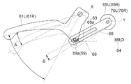
- the interlocking mechanism 66 of the left steering lever 61L and the interlocking mechanism 66 of the right steering lever 61R operate the operation position detection sensors 65L and 65R in conjunction with the swing of the reference stroke [A] of the steering levers 61L and 61R.
- the steering levers 61L and 61R and the operation position detection sensors 65L and 65R are linked and connected in such a state that the amount of change becomes larger as the operation position of the steering levers 61L and 61R approaches the stroke end on the grip side.
- the operation position detection sensors 65L and 65R are supported by the steering handle 4 via the bracket 67.
- the operation position detection sensors 65L and 65R are constituted by a rotary potentiometer.
- the interlocking mechanism 66 of the left steering lever 61L and the right steering lever 61R includes a swing arm 68 and an interlocking member 69.
- the swing arm 68 extends from the rotation operation portions 70L and 70R of the operation position detection sensors 65L and 65R so as not to be relatively rotatable.
- the swing arm 68 can be swung with the rotation axis of the rotation operation portions 70L and 70R as the swing axis Y, and the operation position detection sensors 65L and 65R are operated by the swing operation.
- the interlocking member 69 extends from the portion of the base of the steering levers 61L and 61R away from the swing axis X toward the inner side of the machine body.
- the interlocking member 69 swings integrally with the steering levers 61L and 61R using the swing axis X as the swing axis.
- the extended end side portion 69 a of the interlocking member 69 is engaged with the elongated connecting hole 68 a of the swing arm 68, and the interlock member 69 can slide relative to the swing arm 68 in the longitudinal direction of the swing arm.
- the swing arm 68 is engaged with the swing arm 68 so that the swing arm 68 can be swung.
- the swing axis Y of the swing arm 68 and the swing axis X of the steering levers 61L and 61R are misaligned and parallel or substantially parallel.
- the interlocking member 69 presses and swings the swing arm 68 by the extended end side portion 69a, and the swing arm 68 rotates the operation position detection sensors 65L and 65R.
- the parts 70L and 70R are rotated.
- the extending end portion 69a of the interlocking member 69 slides to the free end side of the swinging arm 68 and receives the swinging operation by the interlocking member 69.
- the position 68 changes to the free end side.
- the swing arm 68 swings by the swing angle [B] by the operation of the interlocking member 69.
- the operation position detection sensors 65L and 65R respond more sensitively to the movement of the steering levers 61L and 61R.
- the operation position of the left steering lever 61L is detected by the left operation position detection sensor 65L.
- the operation position of the right steering lever 61R is detected by the right operation position detection sensor 65R.
- the detected operation position becomes an operation position that is displaced toward the stroke end on the grip side from the actual operation position. In this state, as the steering levers 61L and 61R are closer to the stroke end on the grip side, the detected position is detected in a state where the displacement between the detected operation position and the actual operation position becomes larger.
- the control device 71 is configured using a microcomputer and includes a steering control unit 72 (hereinafter referred to as a steering control unit 72).
- the steering control unit 72 operates the seesaw member 51 to the neutral position [N] based on information detected by the left and right operation position detection sensors 65L and 65R. Therefore, the electric motor 49 is controlled.
- the steering control unit 72 moves the seesaw member 51 from the neutral position [N] to the left turning direction [LS] based on information detected by the left operation position detection sensor 65L.
- the electric motor 49 is controlled so that the left steering brake 38L is provided with a braking force having a strength corresponding to the detected operation position by the left operation position detection sensor 65L.
- the steering control unit 72 moves the seesaw member 51 from the neutral position [N] to the right turning direction [RS] based on information detected by the right operation position detection sensor 65R.
- the electric motor 49 is controlled so that the right steering brake 38R is provided with a braking force having a strength corresponding to the detection operation position by the right operation position detection sensor 65R.
- the left and right steering clutches 37L and 37R and the left and right steering brakes 38L and 38R can be operated, and the steering body 3 can be steered.
- the seesaw member 51 is neutralized by the control of the electric motor 49 by the steering control unit 72 based on the detection information of the left and right operation position detection sensors 65L and 65R.
- the left and right steering clutches 37L, 37R are operated to the engaged state by operating to the position [N], and the traveling machine body 3 travels straight.
- the seesaw member 51 is turned from the neutral position [N] to the left turning direction by the control of the electric motor 49 by the steering control unit 72 based on the detection information of the left operation position detection sensor 65L.
- LS] and the left steering clutch 37L is operated in the disengaged state, or the left steering brake 38L is operated in the engaged state, and the traveling machine body 3 turns leftward.
- the left steering brake 38L is turned on, the left steering brake 38L is applied to the left crawler travel device 2 with a stronger braking force as the grip operation stroke of the left steering lever 61L is increased. The brake becomes stronger and the left turn radius of the traveling machine body 3 becomes smaller.
- the seesaw member 51 turns rightward from the neutral position [N] by the control of the electric motor 49 by the steering control unit 72 based on the detection information of the right operation position detection sensor 65R.
- the right steering clutch 37R is operated in the disengaged state by swinging to [RS], or the right steering brake 38R is operated in the engaged state, and the traveling machine body 3 turns to the right.
- the right steering brake 38R enters the engaged state, the right steering brake 38R is applied to the right crawler traveling device 2 with a stronger braking force as the grip operation stroke of the right steering lever 61R is increased. The brake becomes stronger and the rightward turning radius of the traveling machine body 3 becomes smaller.
- the operation position detection sensors 65L and 65R respond more sensitively to the movements of the steering levers 61L and 61R, so that the steering brakes 38L and 38R are effective.
- the steering levers 61L and 61R are slightly operated, the effectiveness of the steering brakes 38L and 38R changes only slightly and it is easy to finely adjust the braking force.
- the steering brakes 38L and 38R are greatly changed by slightly operating the steering levers 61L and 61R, and the steering brakes 38L and 38R have a strong braking force. Easy to operate quickly to the state.
- the snow removal portion 10 is supported by the support frame 75 by connecting the blower case 12 to the front end portion of the support frame 75.
- the engine 5 is supported by the support frame 75 in a state of being placed on the support frame 75.
- the traveling mission 30 is supported at the lower part of the support frame 75.
- the traveling mission 30 has a pair of left and right cylindrical shapes that extend laterally outward from the lateral sides of the mission case 44 and have output shafts 30 ⁇ / b> L and 30 ⁇ / b> R.
- the left and right output case portions 44L and 44R are supported by the lateral side portion 75a of the support frame 75, and the rear portion of the mission case 44 is supported by the rear portion 75b of the support frame 75.
- the support frame 75 is supported by the traveling machine body 3 so as to be able to swing up and down with the rotation axis of the drive wheel body 25 of the left and right crawler traveling devices 2 as the swing axis Z. Specifically, the support frame 75 is positioned between the left and right track frame portions 20, and the left output case portion 44L of the traveling mission 30 is supported by the left track frame portion 20 of the body frame 1 so as to be relatively rotatable. The right output case portion 44R of the traveling mission 30 is supported by the right track frame portion 20 of the body frame 1 so as to be relatively rotatable.
- the support frame 75 is provided with an operation arm portion 76 extending rearward from the rear portion of the support frame 75.
- An elevating drive mechanism 77 is provided across the extended end portion of the operation arm portion 76 and the body frame 1. The elevating drive mechanism 77 is driven to swing the support frame 75 up and down relative to the body frame 1, and is stopped to fix the support frame 75 to the adjusted swing position.
- the snow removal unit 10 By operating the lifting drive mechanism 77, the snow removal unit 10 can be adjusted up and down with respect to the traveling machine body 3, and the height of the snow removal unit 10 with respect to the ground can be adjusted.
- the support frame 75 swings up and down with the rotation axis of the drive wheel body 25 of the left and right crawler travel device 2 as the oscillation axis Z, and the snow removal unit 10 and the engine 5 and the traveling mission 30 integrally swing up and down with the rotational axis of the left and right drive wheel bodies 25 as the swing axis Z, so that a work transmission system that transmits driving force from the engine 5 to the snow removal unit 10; It is not necessary to provide a special accommodation structure for allowing the snow removal unit 10 to move up and down in the traveling transmission system that transmits the driving force from the engine 5 to the left and right crawler traveling devices 2. Further, even if the ground height of the snow removal unit 10 is changed, the ground posture of the traveling machine body 3 does not change, and the ground posture of the
- the lift drive mechanism 77 includes a rack gear 78, a pinion gear 79, and an electric motor 80.
- the rack gear 78 and the pinion gear 79 are engaged with each other.
- An intermediate gear 79 a is supported on the rotation support shaft of the pinion gear 79 so as not to be relatively rotatable.
- An output gear 80a meshed with the intermediate gear 79a is supported by the electric motor 80 so as to be rotationally driven.
- the pinion gear 79 and the output gear 80a of the electric motor 80 are linked and connected via an intermediate gear 79a.
- the rack gear 78 is supported by the traveling machine body 3 so as to protrude upward from the machine body frame 1. Specifically, a lower end portion of a member 78a including the rack gear 78 is supported by the bracket 85 via a support shaft 78b so as to be relatively rotatable.
- the bracket 85 is supported by the connection frame portion 21 of the body frame 1.
- the pinion gear 79, the intermediate gear 79a, and the electric motor 80 are supported by the support member 81.
- the support member 81 is supported by the rear end portion 76a of the operation arm portion 76 via the support shaft 81a so as to be relatively rotatable.
- the rack gear 78 is supported by the body frame 1 and the pinion gear 79 is supported by the support frame 75.
- the rack gear 78 is supported by the support frame 75 and the pinion gear 79 is supported by the body frame 1.
- a supported configuration may be employed.
- a guide groove 82 is provided in a member 78 a including the rack gear 78.
- a guide pin 83 slidably engaged with the guide groove 82 is supported by the support member 81.
- the guide pin 83 supports a detachment preventing member 86.
- the come-off preventing member 86 prevents the rack gear 78 and the pinion gear 79 from separating from each other by preventing the member 78 a and the support member 81 from being separated.
- the elevating drive mechanism 77 drives the pinion gear 79 by the driving force of the electric motor 80, moves the pinion gear 79 up and down along the rack gear 78, and moves the support frame 75 up and down on the rear end side of the operation arm portion 76. Swing operation.
- the elevating drive mechanism 77 applies an elevating operation force to the support frame 75 at a location near the rear portion of the crawler belt 27 and away from the swing axis Z of the support frame 75 (the rotation axis of the drive wheel 25). With the small electric motor 80, the lifting / lowering adjustment of the snow removal unit 10 can be performed smoothly.
- the elevating drive mechanism 77 is disposed at a position near the rear portion of the crawler belt 27 between the left and right crawler travel devices 2.
- the elevating drive mechanism 77 applies an elevating operation force at a position away from the rotational axis of the drive wheel body 25 to the vicinity of the rear part of the crawler belt 27. Therefore, the elevating drive mechanism 77 is small and light in which the electric motor 80 serves as a power source. In any case, the support frame 75 can be smoothly swung up and down by the lift drive mechanism 77.
- the elevating drive mechanism 77 is located behind the engine 5. Since the lifting drive mechanism 77 swings the support frame 75 behind the portion where the load of the engine 5 is applied, the operating force of the lifting drive mechanism 77 can be efficiently applied to the swing operation of the support frame 75.
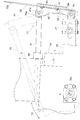
- the elevating drive mechanism 77 is located behind the rear end 1r of the body frame 1. Specifically, in a state where the snow removal unit 10 has risen to the ascent limit, as shown by a solid line in FIG. 6, the entirety from the lower end to the upper end of the elevating drive mechanism 77 is located behind the rear end 1r. In the state where the snow removal unit 10 is lowered to the lower limit, as shown by a two-dot chain line in FIG. 6, the lower end side portion of the elevating drive mechanism 77 is located behind the rear end 1r.
- the distance from the rotational axis of the drive wheel 25 to the elevating drive mechanism 77 can be increased, and the operating force of the elevating drive mechanism 77 can be used as a support frame. 75 can be efficiently operated in the swing operation. It is more preferable that the entire lifting drive mechanism 77 is positioned behind the rear end 1r regardless of the position of the lifting range from the lowering limit to the rising limit.
- the elevating drive mechanism 77 and the power source battery 84 are arranged in the lateral direction of the traveling machine body. Protrusion of the battery 84 to the rear of the lifting drive mechanism 77 can be suppressed. In addition, the battery 84 is unlikely to be an obstacle to the inspection and repair work of the lifting drive mechanism 77 from the rear of the traveling machine body.
- the lifting operation switch 87 is supported by the right steering handle 4 in a state where it is located on the lateral inner side of the grip portion 4 b of the right steering handle 4.
- the raising / lowering operation switch 87 is located in the site
- a support member 89 extends rearward from the boss portion 88.
- a lifting operation switch 87 is supported on the extended end of the support member 89. In this embodiment, the lifting operation switch 87 is supported by the right steering handle 4, but may be supported by the left steering handle 4.
- the control device 71 is a controller 90 for raising and lowering (hereinafter referred to as an elevator controller 90). ).
- the elevating control unit 90 moves the pinion gear 79 to the ascending and descending operation positions corresponding to the operation information and stops the operation based on the input operation information. 80 is controlled.
- the elevating control unit 90 controls the electric motor 80 to the lowering side, and the snow removing unit 10 can be operated to descend.
- the lifting control unit 90 controls the electric motor 80 to the rising side, and the snow removal unit 10 can be lifted. While the lifting operation switch 87 is being pressed, the snow removal unit 10 continues to rise and fall unless the snow removal unit 10 reaches the stroke end.
- a headlamp 92 is supported by the traveling machine body 3. Specifically, the headlamp 92 is supported by the steering handle 4 via the upper reinforcing rod 6. The headlamp 92 is supported in a state in which the vertical adjustment in the mounting direction is possible. The headlamp 92 is displaced with respect to the shooter 15 in the lateral direction of the traveling machine body. It is possible to work while illuminating the front of the snow removal unit 10 and the like with the headlamp 92 and illuminating the shooter 15 in a state in which the shooter 15 does not easily become an obstacle to illumination.
- the headlamp 92 Since the headlamp 92 is supported by the traveling machine body 3 that supports the support frame 75 so as to be swingable up and down, the posture of the headlamp 92 does not change even when the snow removal unit 10 is adjusted up and down. That is, even if the snow removal unit 10 is adjusted up and down, the lighting condition such as the illumination range of the headlamp 92 does not change.
- the hydraulic oil tank 93 is supported by the traveling machine body 3. Specifically, as shown in FIG. 3, the hydraulic oil tank 93 is supported by the steering handle 4 via the lower reinforcing rod 7.
- the hydraulic oil tank 93 and the HST 32 are communicated with each other by an oil supply path 94.
- the oil supply passage 94 is formed by a flexible hose and has flexibility. That is, the oil supply path 94 absorbs the change in the positional relationship between the HST 32 and the hydraulic oil tank 93 due to the vertical adjustment of the snow removal unit 10 by bending.
- the hydraulic oil is automatically supplied to the HST 32 by storing the hydraulic oil in the hydraulic oil tank 93.
- the hydraulic oil tank 93 is made of a material that allows the internal hydraulic oil to be seen through. The amount of oil inside can be seen without opening the lid of the hydraulic oil tank 93. Since the hydraulic oil tank 93 is supported by the traveling machine body 3 that supports the support frame 75 so as to swing up and down, the hydraulic oil tank 93 does not tilt even if the snow removal unit 10 is adjusted up and down.
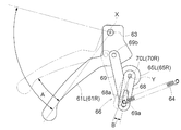
- FIG. 15 is a side view showing the interlocking mechanism 66 having another embodiment structure in a state where the steering brakes 38L and 38R are weakly entered and operated.
- FIG. 16 is a side view showing the interlocking mechanism 66 having another embodiment structure in a state where the steering levers 61L and 61R are operated near the stroke end on the grip side.
- the interlocking member 69 is constituted by a swing link.
- the end of the interlocking member 69 on the side of the steering lever and the part of the steering levers 61L and 61R that are separated from the swing axis X are connected via the support shaft 69b so as to be relatively rotatable.
- the interlocking member 69 oscillates with respect to the steering levers 61L and 61R with the axis of the support shaft 69b parallel to or substantially parallel to the oscillation axis X as the oscillation axis.
- the steering handle 4 is not limited to be provided on the traveling machine body 3, and the steering handle 4 may be provided on the support frame 75.
- the lifting drive mechanism 77 includes the rack gear 78, the pinion gear 79, and the electric motor 80.
- the lifting drive mechanism 77 may be configured by a hydraulic cylinder, an electric cylinder, or the like. .
- the support frame 75 is configured to swing with the rotation axis of the drive wheel body 25 as the swing axis Z.
- the support frame 75 is limited to the rotation axis of the drive wheel body 25.
- the rotating shaft core of the driven wheel body 26 may be configured to swing as a swing shaft core, or the shaft core set at various other locations may be swung as a swing shaft core.
- a crawler traveling device driven by an electric motor may be provided.
- the present invention can be applied to a walking type snowplow provided with a crawler traveling device driven by an electric motor.
- the elevating drive mechanism 77 includes the electric motor 80, the rack gear 78, and the pinion gear 79 is shown, but a hydraulic cylinder or an electric cylinder may be provided as the elevating drive mechanism.
- the swing axis Z of the support frame 75 and the rotation axis of the drive wheel body 25 coincide with each other is shown.
- the swing axis of the support frame 75 may be positioned at any part such as the part that coincides with the rotational axis of the driven wheel 26.
- a crawler traveling device driven by an electric motor may be provided.
Landscapes
- Engineering & Computer Science (AREA)
- Architecture (AREA)
- Civil Engineering (AREA)
- Structural Engineering (AREA)
- Cleaning Of Streets, Tracks, Or Beaches (AREA)
Abstract
除雪部とエンジンとの一体的な上下揺動操作を可能にしつつ、走行伝動系の構造を簡素化しつつ、除雪部及びクローラ走行装置を同一のエンジンによって駆動可能にする。小型かつ軽量な昇降駆動機構によって除雪部を昇降調節可能にする。除雪部10、エンジン5、走行ミッション30が支持フレーム75に支持されている。支持フレーム75は、クローラ走行装置2の駆動輪体25の回転軸芯を揺動軸芯Zとして上下揺動可能に走行機体3に支持されている。支持フレーム75を揺動操作する昇降駆動機構77は、電動モータを動力源として備えていると共に左右のクローラ走行装置2の間におけるクローラベルト27の後部付近に配備されている。
Description
本発明は、歩行型除雪機に関する。
[1]例えば特許文献1に示される歩行型除雪機では、走行フレームの上に車体フレームの後部を上下スイング可能に取付けている。車体フレームは、除雪作業装置とエンジンとを備えている。昇降機構により、車体フレームの前部を上下にスイングさせることができる。車体フレームと共に除雪作業装置を上下にスイングさせることで除雪作業装置の高さを調節することができる。
[2]例えば特許文献2に示される歩行型除雪機では、本機が昇降シリンダによってクローラ走行装置に対して上下揺動操作される。本機の前部に除雪部が連結されている。除雪部に駆動力を伝達するエンジンが本機に内装されている。
また、特許文献2に示される歩行型除雪機では、本機に操作部が配設され、この操作部にハンドルが配備されている。操作部に操作パネルが配置され、この操作パネルにオーガハウジング昇降用スイッチが設けられている。
また特許文献2に示される歩行型除雪機では、本機にボンネットが備えられ、このボンネットから作業灯が突設されている。
また、特許文献2に示される歩行型除雪機では、本機に操作部が配設され、この操作部にハンドルが配備されている。操作部に操作パネルが配置され、この操作パネルにオーガハウジング昇降用スイッチが設けられている。
また特許文献2に示される歩行型除雪機では、本機にボンネットが備えられ、このボンネットから作業灯が突設されている。
[1]背景技術[1]に対する課題は、以下の通りである。
左右一対のクローラ走行装置を有した走行機体と、走行機体に上下揺動可能に支持された支持フレームと、支持フレームに支持され、走行機体の前方で除雪作業する除雪部と、支持フレームに支持され、除雪部に駆動力を出力するエンジンと、支持フレームを揺動操作する昇降駆動機構と、を備える歩行型除雪機においては、昇降駆動機構によって支持フレームを上下揺動操作することにより、走行機体に対して除雪部が上下揺動し、除雪部の対地高さを調節できる。そして、除雪部に出力するエンジンが除雪部と共に昇降するので、エンジンから除雪部に駆動力を伝達する作業伝動系に除雪部の昇降を可能にする特別な融通構造を設ける必要がない。
特許文献1に示される歩行型除雪機では、エンジンを支持する車体フレームの後部が走行フレームの上に上下スイング可能に取付けられている。このため、除雪部とエンジンとを一体的に走行機体に対して上下揺動操作することを可能にしつつ、除雪部及び走行装置を同じエンジンによって駆動することを可能にするに当たり、特許文献1に示される技術を採用した場合、エンジンからクローラ走行装置に駆動力を伝達する走行伝動系に、除雪部及びエンジンの一体的な揺動を可能にする融通構造が必要になる。
本発明の第1の目的は、除雪部とエンジンとの一体的な上下揺動操作を可能にしつつ、かつ走行伝動系の構造を簡素化しつつ、除雪部及びクローラ走行装置を同一のエンジンによって駆動でき、かつ小型かつ軽量な昇降駆動機構によって除雪部を昇降調節できる歩行型除雪機を提供することにある。
左右一対のクローラ走行装置を有した走行機体と、走行機体に上下揺動可能に支持された支持フレームと、支持フレームに支持され、走行機体の前方で除雪作業する除雪部と、支持フレームに支持され、除雪部に駆動力を出力するエンジンと、支持フレームを揺動操作する昇降駆動機構と、を備える歩行型除雪機においては、昇降駆動機構によって支持フレームを上下揺動操作することにより、走行機体に対して除雪部が上下揺動し、除雪部の対地高さを調節できる。そして、除雪部に出力するエンジンが除雪部と共に昇降するので、エンジンから除雪部に駆動力を伝達する作業伝動系に除雪部の昇降を可能にする特別な融通構造を設ける必要がない。
特許文献1に示される歩行型除雪機では、エンジンを支持する車体フレームの後部が走行フレームの上に上下スイング可能に取付けられている。このため、除雪部とエンジンとを一体的に走行機体に対して上下揺動操作することを可能にしつつ、除雪部及び走行装置を同じエンジンによって駆動することを可能にするに当たり、特許文献1に示される技術を採用した場合、エンジンからクローラ走行装置に駆動力を伝達する走行伝動系に、除雪部及びエンジンの一体的な揺動を可能にする融通構造が必要になる。
本発明の第1の目的は、除雪部とエンジンとの一体的な上下揺動操作を可能にしつつ、かつ走行伝動系の構造を簡素化しつつ、除雪部及びクローラ走行装置を同一のエンジンによって駆動でき、かつ小型かつ軽量な昇降駆動機構によって除雪部を昇降調節できる歩行型除雪機を提供することにある。
[2]背景技術[2]に対する第1の課題は、以下の通りである。
左右一対のクローラ走行装置を有した走行機体と、走行機体の前方で除雪作業する除雪部と、除雪部に駆動力を出力するエンジンと、左右一対の操縦ハンドルとを備える歩行型除雪機においては、除雪部及びエンジンを一体的に走行機体に対して上下揺動操作できるよう構成することで、除雪部の対地高さを調節できる。そして、エンジンの出力を除雪部に伝達する作業伝動系に、除雪部の対地高さ調節を可能にする特別な融通構造を設けることを不要にできる。
左右一対のクローラ走行装置を有した走行機体と、走行機体の前方で除雪作業する除雪部と、除雪部に駆動力を出力するエンジンと、左右一対の操縦ハンドルとを備える歩行型除雪機においては、除雪部及びエンジンを一体的に走行機体に対して上下揺動操作できるよう構成することで、除雪部の対地高さを調節できる。そして、エンジンの出力を除雪部に伝達する作業伝動系に、除雪部の対地高さ調節を可能にする特別な融通構造を設けることを不要にできる。
特許文献1にも同様の技術が開示されているが、この種の歩行型除雪機では、走行機体に上下揺動操作可能に支持される支持フレームを設け、この支持フレームに除雪部及びエンジンを支持されるが、走行機体に対する支持フレームの取付け高さが高くなるほど、エンジンの配置高さが高くなり、エンジン重量のために除雪機全体の重心高さが高くなる。
本発明の第2の目的は、除雪機全体の重心高さを低くしつつ、除雪部及びエンジンを一体的に走行機体に対して上下揺動操作できる歩行型除雪機を提供することにある。
[3]背景技術[2]に対する第2の課題は、以下の通りである。
左右一対のクローラ走行装置を有した走行機体と、走行機体に上下揺動可能に支持された支持フレームと、支持フレームに支持され、走行機体の前方で除雪作業する除雪部と、支持フレームに支持され、除雪部に駆動力を出力するエンジンと、電動モータの駆動力によって支持フレームを揺動操作する昇降駆動機構と、を備えた歩行型除雪機においては、昇降駆動機構によって支持フレームを上下揺動操作することにより、走行機体に対して除雪部が昇降し、除雪部の対地高さを調節できる。そして、除雪部に出力するエンジンが除雪部と共に昇降するので、エンジンから除雪部に駆動力を伝達する作業伝動系に除雪部の昇降を可能にする特別な融通構造を設ける必要がない。
この種の歩行型除雪機において、操縦ハンドル、及び電動モータを操作する昇降操作スイッチを設けるのに、特許文献2の技術を採用した場合、除雪部の対地高さを調節すると、操縦ハンドル及び昇降操作スイッチが除雪部と共に上下揺動するので、操縦ハンドルの姿勢が変化して操縦ハンドルの持ち具合が変化しがちである。また、昇降操作スイッチの姿勢が変化して昇降操作スイッチの操作具合が変化しがちである。
この種の歩行型除雪機において、操縦ハンドル、及び電動モータを操作する昇降操作スイッチを設けるのに、特許文献2の技術を採用した場合、除雪部の対地高さを調節すると、操縦ハンドル及び昇降操作スイッチが除雪部と共に上下揺動するので、操縦ハンドルの姿勢が変化して操縦ハンドルの持ち具合が変化しがちである。また、昇降操作スイッチの姿勢が変化して昇降操作スイッチの操作具合が変化しがちである。
本発明の第3の目的は、エンジンが除雪部と共に上下揺動するものでありながら、上記した問題を回避できる歩行型除雪機を提供することにある。
[4]背景技術[2]に対する第3の課題は、以下の通りである。
走行機体と、走行機体に上下揺動可能に支持された支持フレームと、支持フレームに支持され、走行機体の前方で除雪作業する除雪部と、支持フレームに支持され、除雪部に駆動力を出力するエンジンと、支持フレームを揺動操作する昇降駆動機構と、を備えた歩行型除雪機においては、昇降駆動機構によって支持フレームを揺動操作することにより、走行機体に対して除雪部が昇降し、除雪部の対地高さを調節できる。そして、除雪部に出力するエンジンが除雪部と共に昇降するので、エンジンから除雪部に駆動力を伝達する作業伝動系に除雪部の昇降を可能にする特別な融通構造を設ける必要がない。
走行機体と、走行機体に上下揺動可能に支持された支持フレームと、支持フレームに支持され、走行機体の前方で除雪作業する除雪部と、支持フレームに支持され、除雪部に駆動力を出力するエンジンと、支持フレームを揺動操作する昇降駆動機構と、を備えた歩行型除雪機においては、昇降駆動機構によって支持フレームを揺動操作することにより、走行機体に対して除雪部が昇降し、除雪部の対地高さを調節できる。そして、除雪部に出力するエンジンが除雪部と共に昇降するので、エンジンから除雪部に駆動力を伝達する作業伝動系に除雪部の昇降を可能にする特別な融通構造を設ける必要がない。
この種の歩行型除雪機において、特許文献2に示される技術を採用して前照灯及び操縦ハンドルを装備した場合、除雪部の対地高さを調節すると、前照灯が除雪部と共に上下揺動するので、前照灯の姿勢が変化して照明具合が変化し易い。これに加え、操縦ハンドルが除雪部と共に上下揺動するので、操縦ハンドルの姿勢が変化し、操縦ハンドルの持ち具合が変化し易い。
本発明の第4の目的は、エンジンが除雪部と共に上下揺動するものでありながら、上記した問題を回避できる歩行型除雪機を提供することにある。
[1]課題[1]に対応する解決手段は、以下の通りである。
左右一対のクローラ走行装置を有した走行機体と、前記走行機体に上下揺動可能に支持された支持フレームと、前記支持フレームに支持され、前記走行機体の前方で除雪作業する除雪部と、前記支持フレームに支持され、前記除雪部に駆動力を出力するエンジンと、前記支持フレームに支持され、前記エンジンから入力された動力を左右の前記クローラ走行装置に分配して伝達する走行ミッションと、前記支持フレームを揺動操作する昇降駆動機構と、を備え、
左右の前記クローラ走行装置は、前記走行機体の前部に駆動回転可能に支持された駆動輪体と、前記駆動輪体よりも後方で前記走行機体に回転可能に支持された従動輪体と、前記駆動輪体と前記従動輪体とに亘って巻き掛けられたクローラベルトとを備え、
前記支持フレームは、左右の前記クローラ走行装置の前記駆動輪体の回転軸芯を揺動軸芯として上下揺動可能に支持されており、
前記昇降駆動機構は、電動モータを動力源として備えていると共に左右の前記クローラ走行装置の間における前記クローラベルトの後部付近の位置に配備されている。
左右の前記クローラ走行装置は、前記走行機体の前部に駆動回転可能に支持された駆動輪体と、前記駆動輪体よりも後方で前記走行機体に回転可能に支持された従動輪体と、前記駆動輪体と前記従動輪体とに亘って巻き掛けられたクローラベルトとを備え、
前記支持フレームは、左右の前記クローラ走行装置の前記駆動輪体の回転軸芯を揺動軸芯として上下揺動可能に支持されており、
前記昇降駆動機構は、電動モータを動力源として備えていると共に左右の前記クローラ走行装置の間における前記クローラベルトの後部付近の位置に配備されている。
本構成によると、昇降駆動機構によって支持フレームを上下揺動操作することにより、支持フレームと共に除雪部が上下揺動し、除雪部の対地高さを調節できる。除雪部の対地高さを調節すると、支持フレームと共にエンジンが上下揺動するが、支持フレームが左右のクローラ走行装置の駆動輪体の回転軸芯を揺動軸芯として上下揺動し、かつ支持フレームと共に走行ミッションが上下揺動するので、エンジンの駆動力を左右のクローラ走行装置に伝達する走行伝動系に除雪部及びエンジンの上下揺動を可能にする特別な融通構造を設ける必要がない。
昇降駆動機構は、駆動輪体の回転軸芯からクローラベルトの後部付近まで離れた位置で昇降操作力を付与するので、昇降駆動機構を電動モータが動力源となる小型かつ軽量なものにしても、昇降駆動機構によって支持フレームをスムーズに上下揺動操作できる。
従って、走行伝動系を特別な融通構造が無い簡素な構造のものにしつつ、除雪部を駆動するエンジンによって左右のクローラ走行装置を駆動でき、かつ小型かつ軽量な昇降駆動機構によって除雪部を昇降調節できる。
昇降駆動機構は、駆動輪体の回転軸芯からクローラベルトの後部付近まで離れた位置で昇降操作力を付与するので、昇降駆動機構を電動モータが動力源となる小型かつ軽量なものにしても、昇降駆動機構によって支持フレームをスムーズに上下揺動操作できる。
従って、走行伝動系を特別な融通構造が無い簡素な構造のものにしつつ、除雪部を駆動するエンジンによって左右のクローラ走行装置を駆動でき、かつ小型かつ軽量な昇降駆動機構によって除雪部を昇降調節できる。
一好適実施形態では、前記昇降駆動機構は、前記電動モータによって駆動されるピニオンギヤと、前記ピニオンギヤが咬み合ったラックギヤとを備えている。
本構成によると、ピニオンギヤ及びラックギヤを備えた簡素かつ軽量な動力変換機構によって電動モータの回転駆動力を支持フレーム揺動用の操作力に変換できる。
一好適実施形態では、前記電動モータ及び前記ピニオンギヤが前記支持フレームに支持され、前記ラックギヤが前記走行機体に支持されている。
ラックギヤを備える部材が電動モータ及びピニオンギヤを支持する支持部材よりも走行機体上下方向に長い長尺部材になりがちである。本構成によると、除雪部の高さ調節の際、長尺部材が動かないようにでき、昇降駆動機構を配備し易い。
一好適実施形態では、前記昇降駆動機構は、前記エンジンよりも後方に位置している。
本構成によると、除雪部の昇降調節をするのにエンジンの荷重に抗して支持フレームを揺動操作するのであるが、支持フレームの揺動軸芯からエンジンまでの距離よりも、支持フレームの揺動軸芯から昇降駆動機構までの距離の方が長いので、昇降駆動機構の操作力を支持フレームの揺動操作に効率よく作用させられる。
一好適実施形態では、前記昇降駆動機構は、前記走行機体の機体フレームの後端よりも後方に位置している。
本構成によると、昇降駆動機構が機体フレームの後端よりも前方に位置するものに比べ、駆動輪体の回転軸芯から昇降駆動機構までの距離を長くでき、昇降駆動機構の操作力を支持フレームの揺動操作に効率よく作用させられる。
一好適実施形態では、前記昇降駆動機構とバッテリーとが走行機体横幅方向に並んでいる。
本構成によると、昇降駆動機構よりも後方へのバッテリーの突出を抑制でき、バッテリーが走行機体の後方を歩行することの障害になり難い。
[2]課題[2]に対応する解決手段は、以下の通りである。
左右一対のクローラ走行装置を有した走行機体と、前記走行機体に上下揺動可能に支持された支持フレームと、前記支持フレームに支持され、前記走行機体の前方で除雪作業する除雪部と、前記支持フレームに支持され、前記除雪部に駆動力を出力するエンジンと、前記支持フレームを揺動操作する昇降駆動機構と、を備え、
前記走行機体の機体フレームは、左右の前記クローラ走行装置を各別に支持する左右一対の走行機体前後向きのトラックフレーム部と、左右の前記トラックフレーム部の後部を連結する走行機体横向きの連結フレーム部とを備え、
前記支持フレームは、左右の前記トラックフレーム部の間に位置した状態で左右の前記トラックフレーム部に上下揺動可能に支持されており、
前記連結フレーム部の左右端部から左右一対の操縦ハンドルが延出されている。
前記走行機体の機体フレームは、左右の前記クローラ走行装置を各別に支持する左右一対の走行機体前後向きのトラックフレーム部と、左右の前記トラックフレーム部の後部を連結する走行機体横向きの連結フレーム部とを備え、
前記支持フレームは、左右の前記トラックフレーム部の間に位置した状態で左右の前記トラックフレーム部に上下揺動可能に支持されており、
前記連結フレーム部の左右端部から左右一対の操縦ハンドルが延出されている。
本構成によると、昇降駆動機構を操作すると、除雪部及びエンジンを支持している支持フレームがトラックフレーム部に対して上下揺動操作されるので、除雪部及びエンジンを一体的に走行機体に対して上下揺動操作できる。
機体フレームは、左右のトラックフレーム部及び連結フレーム部を備え、左右一対の操縦ハンドルが連結フレーム部から延出しているので、機体フレームにおける左右のトラックフレーム部の間に空きスペースを得られる。支持フレームが左右のトラックフレーム部の間に位置した状態で左右のトラックフレーム部に上下揺動可能に支持されているので、支持フレームを機体フレームの空きスペースに入り込ませ、支持フレームの走行機体への取付け高さを低くできる。支持フレームの取付け高さを低くできることで、エンジンの配置高さを低くできる。
また、支持フレームを上下揺動可能に支持する機体フレームにおける連結フレーム部に操縦ハンドルが支持されているので、除雪部の対地高さ調節をしても、操縦ハンドルの姿勢が変化せず、除雪部の高さ調節にかかわらず、操縦ハンドルの握り具合が変化しない。
従って、エンジンの出力を除雪部に伝達する作業伝動系に除雪部の対地高さ調節を可能にする特別な融通構造を設けずに除雪部の対地高さ調節をできるものでありながら、エンジンの配置高さを低くできることで、除雪機全体の重心高さを低くして歩行型除雪機を安定よく走行させられる。
機体フレームは、左右のトラックフレーム部及び連結フレーム部を備え、左右一対の操縦ハンドルが連結フレーム部から延出しているので、機体フレームにおける左右のトラックフレーム部の間に空きスペースを得られる。支持フレームが左右のトラックフレーム部の間に位置した状態で左右のトラックフレーム部に上下揺動可能に支持されているので、支持フレームを機体フレームの空きスペースに入り込ませ、支持フレームの走行機体への取付け高さを低くできる。支持フレームの取付け高さを低くできることで、エンジンの配置高さを低くできる。
また、支持フレームを上下揺動可能に支持する機体フレームにおける連結フレーム部に操縦ハンドルが支持されているので、除雪部の対地高さ調節をしても、操縦ハンドルの姿勢が変化せず、除雪部の高さ調節にかかわらず、操縦ハンドルの握り具合が変化しない。
従って、エンジンの出力を除雪部に伝達する作業伝動系に除雪部の対地高さ調節を可能にする特別な融通構造を設けずに除雪部の対地高さ調節をできるものでありながら、エンジンの配置高さを低くできることで、除雪機全体の重心高さを低くして歩行型除雪機を安定よく走行させられる。
一好適実施形態では、前記機体フレームは、前記連結フレーム部の左右端部から上方向きに突設されたハンドル支持フレーム部を備え、左右の前記操縦ハンドルは、前記ハンドル支持フレーム部に支持されることで前記連結フレーム部に支持されている。
本構成によると、操縦ハンドルを連結するための広い連結面をハンドル支持フレーム部によって連結フレーム部に備えさせ、操縦ハンドルをしっかり支持できる。
一好適実施形態では、左右の前記ハンドル支持フレーム部は、板厚方向が走行機体横幅方向となった板状部材によって構成され、左右の前記操縦ハンドルは、前記ハンドル支持フレーム部の機体横外側の側面に支持されている。
本構成によると、左右のハンドル支持フレーム部の間隔を広くして、左右のハンドル支持フレーム部の間をバッテリーなどの配備に使い易くしつつ、操縦ハンドルをハンドル支持フレーム部の側面にしっかり支持できる。
一好適実施形態では、左右の前記操縦ハンドルは、丸パイプ材によって構成され、
左右の前記操縦ハンドルの前記ハンドル支持フレーム部に支持されている基部は、外周面の一部が前記ハンドル支持フレーム部の側面に沿った平坦面になった状態に押圧変形処理されている。
左右の前記操縦ハンドルの前記ハンドル支持フレーム部に支持されている基部は、外周面の一部が前記ハンドル支持フレーム部の側面に沿った平坦面になった状態に押圧変形処理されている。
本構成によると、操縦ハンドルを丸パイプ材によって丈夫に構成しつつ、基部の平坦面がハンドル支持フレーム部の側面に沿うことによってハンドル支持フレーム部にしっかり連結できる。
一好適実施形態では、前記支持フレームに支持され、前記エンジンから入力された動力を左右の前記クローラ走行装置に分配して伝達する走行ミッションを備え、左右の前記クローラ走行装置は、前記トラックフレーム部の前部に駆動回転可能に支持された駆動輪体と、前記駆動輪体よりも後方で前記トラックフレーム部に回転可能に支持された従動輪体と、前記駆動輪体と前記従動輪体とに亘って巻き掛けられたクローラベルトとを備え、前記支持フレームは、左右の前記クローラ走行装置の前記駆動輪体の回転軸芯を揺動軸芯として上下揺動可能に支持されている。
本構成によると、エンジンの出力を左右のクローラ走行装置に伝達する走行伝動系に特別な融通構造を設けずに、走行ミッションをエンジンと一体的に走行機体に対して上下揺動させることができる。つまり、走行伝動系を特別な融通構造がない構造簡単なものにしつつ、除雪部の対地高さ調節をできる。
[3]課題[3]に対応する解決手段は、以下の通りである。
左右一対のクローラ走行装置を有した走行機体と、前記走行機体に上下揺動可能に支持された支持フレームと、前記支持フレームに支持され、前記走行機体の前方で除雪作業する除雪部と、前記支持フレームに支持され、前記除雪部に駆動力を出力するエンジンと、電動モータの駆動力によって前記支持フレームを揺動操作する昇降駆動機構と、を備え、
前記走行機体に操縦ハンドルが支持され、
前記操縦ハンドルは、走行機体前後向きの握り部を備え、
前記電動モータを操作する昇降操作スイッチが、前記握り部の走行機体横内側のうちの前記握り部を支持している手の指操作が可能な部位に位置する状態で前記操縦ハンドルに支持されている。
前記走行機体に操縦ハンドルが支持され、
前記操縦ハンドルは、走行機体前後向きの握り部を備え、
前記電動モータを操作する昇降操作スイッチが、前記握り部の走行機体横内側のうちの前記握り部を支持している手の指操作が可能な部位に位置する状態で前記操縦ハンドルに支持されている。
本構成によると、昇降駆動機構によって支持フレームを揺動操作して除雪部の対地高さを調節しても、支持フレームが走行機体に対して上下揺動するものであって、走行機体の対地姿勢が変化しないので、操縦ハンドル及び昇降操作スイッチの姿勢が変化しない。
従って、除雪部の対地高さを調節しても、操縦ハンドルの持ち具合が変化しなくて操縦感覚に変化が生じにくい。また、操縦ハンドルの姿勢も、昇降操作スイッチの姿勢も変化しないので、昇降操作スイッチの操作具合が変化し難く、除雪部の対地高さの変更にかかわらず、除雪部を精度良く昇降調節し易いなど作業し易い状態を維持できる。
従って、除雪部の対地高さを調節しても、操縦ハンドルの持ち具合が変化しなくて操縦感覚に変化が生じにくい。また、操縦ハンドルの姿勢も、昇降操作スイッチの姿勢も変化しないので、昇降操作スイッチの操作具合が変化し難く、除雪部の対地高さの変更にかかわらず、除雪部を精度良く昇降調節し易いなど作業し易い状態を維持できる。
一好適実施形態では、前記操縦ハンドルの前記握り部よりも前方の部位に設けられ、クラッチレバーを支持するボス部を備え、前記ボス部から後方向きに延出された支持部材を備え、前記昇降操作スイッチは、前記支持部材に支持されることで前記操縦ハンドルに支持されている。
本構成によると、クラッチレバー用のボス部を支持部材の取付け部に利用した構造簡単な取付け構造で昇降操作スイッチを操縦ハンドルに支持できる。
一好適実施形態では、前記支持フレームに支持され、前記エンジンから入力された動力を左右の前記クローラ走行装置に分配して伝達する走行ミッションを備え、左右の前記クローラ走行装置は、前記走行機体の前部に駆動回転可能に支持された駆動輪体と、前記駆動輪体よりも後方で前記走行機体に回転可能に支持された従動輪体と、前記駆動輪体と前記従動輪体とに亘って巻き掛けられたクローラベルトとを備え、前記支持フレームは、左右の前記クローラ走行装置の前記駆動輪体の回転軸芯を揺動軸芯として上下揺動可能に支持されている。
本構成によると、エンジンからクローラ走行装置に駆動力を伝達する走行伝動系に除雪部の対地高さ調節を可能にするための特別な融通構造を設けずに、除雪部の対地高さ調節をできる。
[4]課題[4]に対応する解決手段は、以下の通りである。
走行機体と、前記走行機体に上下揺動可能に支持された支持フレームと、前記支持フレームに支持され、前記走行機体の前方で除雪作業する除雪部と、前記支持フレームに支持され、前記除雪部に駆動力を出力するエンジンと、前記支持フレームを揺動操作する昇降駆動機構と、を備え、
操縦ハンドル及び前照灯が前記走行機体に支持されている。
操縦ハンドル及び前照灯が前記走行機体に支持されている。
本構成によると、昇降駆動機構によって支持フレームを上下揺動操作して除雪部の対地高さを調節しても、支持フレームが走行機体に対して上下揺動するので、走行機体の対地姿勢が変化せず、前照灯の姿勢も、操縦ハンドルの姿勢も変化しない。
従って、除雪部の対地高さを調節しても、前照灯による照明具合が変化しなくて前方を見易い状態を維持できるので、かつ、操縦ハンドルの持ち具合が変化しなくて操縦感覚などが変化し難いので、除雪部の対地高さの変更にかかわらず、除雪作業をし易い状態を維持し易い。
従って、除雪部の対地高さを調節しても、前照灯による照明具合が変化しなくて前方を見易い状態を維持できるので、かつ、操縦ハンドルの持ち具合が変化しなくて操縦感覚などが変化し難いので、除雪部の対地高さの変更にかかわらず、除雪作業をし易い状態を維持し易い。
一好適実施形態では、前記前照灯は、前記操縦ハンドルに支持されることで前記走行機体に支持されている。
本構成によると、操縦ハンドルを前照灯の支柱部材に利用した構造簡単な支持構造で前照灯の取付け位置を高くできる。
一好適実施形態では、前記除雪部は、雪を掻き集めるオーガと、前記オーガによって掻き集められた雪をブロワによって放出するシュータとを備え、前記前照灯は、前記シュータに対して走行機体横幅方向に位置ずれしている。
本構成によれば、シュータが前照灯による前方照明の障害になり難い。
一好適実施形態では、前記走行機体は、前記走行機体の前部に駆動可能に支持された駆動輪体と、前記駆動輪体よりも後方で前記走行機体に回転可能に支持された従動輪体と、前記駆動輪体と前記従動輪体とに巻き掛けられたクローラベルトとを備え、前記支持フレームは、前記駆動輪体の回転軸芯を揺動軸芯として上下揺動可能に支持されている。
本構成によると、駆動輪体は、従動輪体よりも前方に位置するので、従動輪体の回転軸芯を支持フレームの揺動軸芯にするのに比べ、除雪部の揺動半径を小にしつつ除雪部の対地高さを調節できる。すなわち、除雪部に駆動力を伝達するエンジンによってクローラベルトを駆動する場合、除雪部の揺動半径を小さくしつつ駆動できる。
以下、図面に基づいて、本発明の実施の形態を説明する。
図1は、本発明の実施例に係る歩行型除雪機の全体を示す側面図である。図2は、本発明の実施例に係る歩行型除雪機の全体を示す平面図である。図1,2に示す[F]の方向が走行機体の「前側」、[B]の方向が走行機体の後側、[L]の方向が走行機体の「左側」、[R]の方向が走行機体の[右側]と定義する。
図1は、本発明の実施例に係る歩行型除雪機の全体を示す側面図である。図2は、本発明の実施例に係る歩行型除雪機の全体を示す平面図である。図1,2に示す[F]の方向が走行機体の「前側」、[B]の方向が走行機体の後側、[L]の方向が走行機体の「左側」、[R]の方向が走行機体の[右側]と定義する。
図1に示すように、歩行型除雪機は、機体フレーム1に左右一対のクローラ走行装置2が装備された走行機体3を備えている。走行機体3は、後部に設けられた左右一対の操縦ハンドル4を備え、走行機体3の後方を歩行しつつ走行機体3の走行及び操向操作を行なうよう歩行型に構成されている。走行機体3の前方に除雪部10が配置されている。除雪部10の後方における走行機体3の上方にエンジン5が配置されている。
歩行型除雪機は、走行機体3を走行させることで、除雪部10によって除雪作業を行なえる。すなわち、除雪部10は、オーガハウジング11と、オーガハウジング11の後部に連結されたブロワケース12とを備えている。オーガハウジング11にオーガ13が駆動回転可能に支持されている。ブロワケース12にブロワ14が駆動回転可能に内装されている。ブロワケース12からシュータ15が上方向きに突設されている。オーガ13が雪を掻き集め、シュータ15が掻き集められた雪をブロワ14の噴出力によって放出口15aから放出する。
走行機体3について説明する。
機体フレーム1は、図1,5,7に示すように、左右一対の走行機体前後向きのトラックフレーム部20と、走行機体横向きの連結フレーム部21とを備えている。連結フレーム部21は、左右のトラックフレーム部20の後部を連結している。連結フレーム部21の縦断面形状が前方向きに開口した溝形状になっている。機体フレーム1の平面視形状が前方向きに開口したU字状になっている。機体フレーム1は、図5に示すように、後述する走行ミッション30及び支持フレーム75が入る空きスペースを内部に備えている。
機体フレーム1は、図1,5,7に示すように、左右一対の走行機体前後向きのトラックフレーム部20と、走行機体横向きの連結フレーム部21とを備えている。連結フレーム部21は、左右のトラックフレーム部20の後部を連結している。連結フレーム部21の縦断面形状が前方向きに開口した溝形状になっている。機体フレーム1の平面視形状が前方向きに開口したU字状になっている。機体フレーム1は、図5に示すように、後述する走行ミッション30及び支持フレーム75が入る空きスペースを内部に備えている。
左右のクローラ走行装置2は、図5に示すように、左右のトラックフレーム部20に振り分けて支持されている。左右のクローラ走行装置2は、図1,5に示すように、トラックフレーム部20の前端部に駆動可能に支持された駆動輪体25と、駆動輪体25よりも後方に位置する状態でトラックフレーム部20に回転可能に支持された従動輪体26と、駆動輪体25と従動輪体26とに亘って巻き掛けられたクローラベルト27と、を備えている。図1に示すように、駆動輪体25と従動輪体26との間において、クローラベルト27に外れ止め部材28が係合作用している。外れ止め部材28は、トラックフレーム部20に支持されている。
左右一対の操縦ハンドル4は、図1,5に示すように、連結フレーム部21の左右端部から上方向きに、かつ後方向きに延出されている。具体的には、図5,7に示すように、連結フレーム部21の左右端部にハンドル支持フレーム部22が設けられている。左右のハンドル支持フレーム部22は、連結フレーム部21から上方向きに突設されている。ハンドル支持フレーム部22に操縦ハンドル4の基部4aが支持されている。
左右のハンドル支持フレーム部22は、板状部材によって構成されている。板状部材は、板厚方向が走行機体横幅方向となる取付姿勢で連結フレーム部21に取り付けられている。左右の操縦ハンドル4の基部4aは、ハンドル支持フレーム部22の機体横外側の側面に支持されている。左右の操縦ハンドル4は、丸パイプ部材によって構成されている。
左右の操縦ハンドル4の基部4aは、外周面の一部が平坦面になった状態に押圧変形処理されている。基部4aは、平坦面がハンドル支持フレーム部22の側面に沿う状態でハンドル支持フレーム部22に連結されている。本実施例では、基部4aとハンドル支持フレーム部22とは、連結ボルトによって連結されている。基部4aとハンドル支持フレーム部22との連結手段としては、連結ボルトに限らず、溶接を採用してもよい。
左右の操縦ハンドル4の基部4aは、外周面の一部が平坦面になった状態に押圧変形処理されている。基部4aは、平坦面がハンドル支持フレーム部22の側面に沿う状態でハンドル支持フレーム部22に連結されている。本実施例では、基部4aとハンドル支持フレーム部22とは、連結ボルトによって連結されている。基部4aとハンドル支持フレーム部22との連結手段としては、連結ボルトに限らず、溶接を採用してもよい。
左右の操縦ハンドル4の延出端部に握り部4bが設けられている。左右の操縦ハンドル4の握り部4bは、走行機体3の前後方向に延びている。図1に示すように、左右の操縦ハンドル4の握り部4bと基部4aとの間における部位が一対の補強杆6,7によって連結されている。一対の補強杆6,7は、操縦ハンドル4の上下方向(長手方向)に間隔を空けて並んでいる。左右の操縦ハンドル4は、補強杆6,7による連結によって互いに支持し合うことで、補強し合っている。上側の補強杆6に操作盤8が支持されている。
左右のクローラ走行装置2及び除雪部10は、図4に示す動力伝達構造に基づいてエンジン5から駆動力が伝達されることで駆動される。
すなわち、エンジン5から出力軸5aが前方向きに突設されている。出力軸5aと、走行ミッション30の入力軸30aとに亘って走行クラッチ31が配備されている。本実施例では、走行クラッチ31は、ベルトテンションクラッチによって構成されている。走行クラッチ31としては、ベルトテンションクラッチに限らず、多板式摩擦クラッチなど、型式が各種異なるクラッチを採用してもよい。走行ミッション30の左右の出力軸30L,30Rに左右のクローラ走行装置2の駆動輪体25が相対回転不能に支持されている。
走行ミッション30には、静油圧式無段変速部32(以下、HST32と略称する。)が備えられている。HST32は、入力軸30aの駆動力を可変容量形のアキシャルプランジャポンプ(図示せず)とアキシャルプランジャモータ(図示せず)とによって変速し、変速した後の駆動力を左右の出力軸30L,30Rに伝達する。
走行ミッション30には、静油圧式無段変速部32(以下、HST32と略称する。)が備えられている。HST32は、入力軸30aの駆動力を可変容量形のアキシャルプランジャポンプ(図示せず)とアキシャルプランジャモータ(図示せず)とによって変速し、変速した後の駆動力を左右の出力軸30L,30Rに伝達する。
走行クラッチ31を入り状態に切換え操作し、かつHST32を伝動状態に変速操作することで、エンジン5からの駆動力が左右の駆動輪体25に伝達されて左右のクローラ走行装置2が駆動され、走行機体3を走行させることができる。HST32を変速操作することで、左右のクローラ走行装置2が前進側と後進側とに切り換えて駆動され、かつ左右のクローラ走行装置2の前進駆動速度及び後進駆動速度が無段階に変速され、走行機体3を前進と後進とに切り換えて、かつ前進側及び後進側に無段階に変速して走行させることができる。
走行クラッチ31を切り状態に切換え操作するか、あるいはHST32を中立状態に変速操作することで、左右のクローラ走行装置2への駆動力の伝達が絶たれ、走行機体3を停止させられる。
走行クラッチ31の操作部(テンションプーリ)と、走行用のクラッチレバー33(図1,2参照)とが連係されている。走行用のクラッチレバー33は、左の操縦ハンドル4に支持されている。具体的には、走行用のクラッチレバー33は、左の操縦ハンドル4の握り部4bの上方に上下揺動操作可能に位置している。クラッチレバー33を握り操作することで、走行クラッチ31を入り状態に切換え操作できる。走行用のクラッチレバー33は、デッドマン式に構成されている。つまり、クラッチレバー33を握り操作していることによって走行クラッチ31を入り状態に維持でき、クラッチレバー33の握り操作を解除することによって走行クラッチ31が切り状態になる。図1,2に示すように、HST32を変速操作する変速レバー34は、操作盤8に設けられている。
図4に示すように、エンジン5の出力軸5aと除雪部10の入力軸10aとに亘って作業クラッチ35が装備されている。本実施例では、作業クラッチ35は、ベルトテンションクラッチによって構成されている。作業クラッチ35としては、ベルトテンションクラッチに限らず、多板式摩擦クラッチなど、型式が各種異なるクラッチを採用してもよい。
作業クラッチ35を入り状態に切換え操作することで、エンジン5からの駆動力が入力軸30aに伝達され、オーガ13及びブロワ14を駆動できる。作業クラッチ35を切り状態に切換え操作することで、入力軸30aへの駆動力の伝達が絶たれ、オーガ13及びブロワ14を停止できる。
作業クラッチ35の操作部(テンションプーリ)と、作業用のクラッチレバー36(図2参照)とが連係されている。作業用のクラッチレバー36は、右の操縦ハンドル4に支持されている。具体的には、クラッチレバー36は、右の操縦ハンドル4の握り部4bの上方に上下揺動操作可能に位置している。クラッチレバー36を握り操作することで、作業クラッチ35を入り状態に切換え操作できる。
図14に示すように、走行ミッション30に左右一対の操向クラッチ37L,37R、及び左右一対の操向ブレーキ38L,38Rが設けられている。左右の操向クラッチ37L,37Rは、クラッチ輪体39L,39Rを備えている。クラッチ輪体39L,39Rは、出力軸30L,30Rのスプライン部の外周部にスライド可能に、かつ相対回転不能に嵌合されている。クラッチ輪体39L,39Rと出力ギヤ40とに亘って爪クラッチ機構41L,41Rが設けられている。出力ギヤ40は、左右の出力軸30L,30Rとは相対可能な状態で左右の出力軸30L,30Rに支持されている。出力ギヤ40は、HST32の出力によって駆動される。クラッチ輪体39L,39Rにシフター42L,42Rが係合されている。左右のシフター42L,42Rは、回転支軸43L,43Rを介してミッションケース44(図9参照)に揺動可能に支持されている。図9に示すように、ミッションケース44の外部において、左右の回転支軸43L,43Rに操作アーム45L,45Rが相対回転不能に支持されている。
操作アーム45L,45Rの揺動操作によってシフター42L,42Rが揺動操作されることで、クラッチ輪体39L,39Rが出力ギヤ40に寄せ操作されたり、出力ギヤ40から離し操作されたりする。クラッチ輪体39L,39Rが出力ギヤ40に寄せ操作されることで、爪クラッチ機構41L,41Rが入り状態に操作される。クラッチ輪体39L,39Rが出力ギヤ40から離間操作されることで、爪クラッチ機構41L,41Rが切り状態に操作される。
左右の操向クラッチ37L,37Rは、爪クラッチ機構41L,41Rが入り状態に操作されることで、入り状態になり、爪クラッチ機構41L,41Rが切り状態に操作されることで、切り状態になる。左右の操向クラッチ37L,37Rは、入り状態に操作されることで、出力ギヤ40と出力軸30L,30Rとを連動連結して、HST32の出力を駆動輪体25に伝達する。左右の操向クラッチ37L,37Rは、爪クラッチ機構41L,41Rが切り状態に操作されることで、出力ギヤ40と出力軸30L,30Rとの連動連結を解除して、HST32からクローラ走行装置2への動力伝達を絶つ。
左右の操向ブレーキ38L.38Rは、多板式の摩擦クラッチによって構成されている。操向クラッチ37L,37Rを切り状態に切換え操作した操作域において、操作アーム45L,45Rの揺動操作によってシフター42L,42Rが揺動操作されることで、クラッチ輪体39L,39Rがクラッチ入り付勢バネ46に抗して操向ブレーキ38L,38Rに寄せ操作されたり、操向ブレーキ38L,38Rから離し操作されたりする。
左右の操向ブレーキ38L,38Rは、寄せ操作されたクラッチ輪体39L,39Rの操作部39a,39bによって押圧操作されることで入り状態になり、クラッチ輪体39L,39Rの離し操作によって操作部39a,39bによる押圧が解除されることで切り状態になる。左右の操向ブレーキ38L,38Rは、入り状態になると、出力軸30L,30Rに摩擦制動力を付与し、クローラ走行装置2にブレーキを掛ける。左右の操向ブレーキ38L,38Rは、クラッチ輪体39L39Rの押圧力が強められるほど、クローラ走行装置2に掛けるブレーキを強くする。左右の操向ブレーキ38L,38Rは、切り状態になると、出力軸30L,30Rへの摩擦制動力の付与を解除し、クローラ走行装置2に掛けるブレーキを解除する。
図9,14に示すように、左右の操作アーム45L,45Rに連係機構50を介して一つのアクチュエータ49が連係されている。左右の操向クラッチ37L,37R及び左右の操向ブレーキ38L,38Rを一つのアクチュエータ49によって操作できる。本実施例では、アクチュエータ49として、電動モータが採用されている。アクチュエータ49としては、電動モータに限らず、シリンダなどの各種の動力源を採用してもよい。以下において、アクチュエータ49を電動モータ49と呼称して説明する。
連係機構50は、図9に示すように、シーソ部材51を備えている。シーソ部材51は、支軸52を介してミッションケース44に支持されている。シーソ部材51は、支軸52の軸芯を揺動軸芯にして揺動操作できる。シーソ部材51の左右端部が左右一対の連動リンク53L,53Rによって左右の操作アーム45L,45Rに連結されている。左右の連動リンク53L,53Rのシーソ部材側の端部54L,54Rは、シーソ部材51の長穴形の連結穴55L,55Rにスライド可能に係入している。
シーソ部材51と電動モータ49とは、扇形ギヤ56、小径ギヤ57、大径ギヤ58及びウオームギヤ59を介して連動連結されている。扇形ギヤ56には、連結アーム部56aが備えられている。連結アーム部56aとシーソ部材51とにわたって支軸52及び連結ピン56bが装着されていることで、扇形ギヤ56とシーソ部材51は、相対回転不能に連結している。扇形ギヤ56と小径ギヤ57とは、噛み合っている。小径ギヤ57と大径ギヤ58とは、回転支軸60を介して連動連結している。大径ギヤ58とウオームギヤ59とは、噛み合っている。ウオームギヤ59は、電動モータ49の出力軸49aに相対回転不能に取り付けられている。
電動モータ49が中立状態に操作されていると、シーソ部材51が中立位置[N]にある。この場合、左右の連動リンク53L,53Rの端部54L,54Rが連結穴55L,55Rのアーム側端部に位置し、左右の操作アーム45L,45Rがリターンバネ47によってクラッチ入り位置に操作されている。すなわち、左右の操向クラッチ37L,37Rが入り状態になっている。
電動モータ49が中立状態から左旋回側に操作されると、シーソ部材51が中立位置[N]から左旋回方向[LS]に揺動操作され、左の連動リンク53Lがシーソ部材51によって引張り操作されて左の操作アーム45Lがクラッチ入り位置からブレーキ入り位置に向けて揺動操作され、左の操向クラッチ37Lが切り状態に切り換わる。左の操向クラッチ37Lが切り状態になった後、シーソ部材51が更に左旋回方向[LS]に揺動操作されると、左の操作アーム45Lがブレーキ位置に操作され、左の操向ブレーキ38Lが入り状態になる。シーソ部材51の左旋回方向[LS]への揺動ストロークが大になるほど、左の操向ブレーキ38Lに対するクラッチ輪体39Lの押圧力が強くなり、左の操向ブレーキ38Lのブレーキ力が強くなる。このように、左の操向クラッチ37Lが切り状態になり、かつ左の操向ブレーキ38Lが入り状態になったとき、右の連結穴55Rが右の操作アーム45Rの方へ移動し、右の操作アーム45Rがリターンバネ47によってクラッチ入り位置に維持され、右の操向クラッチ37Rが入り状態に維持され、かつ右の操向ブレーキ38Rが切り状態に維持される。
電動モータ49が中立状態から右旋回側に操作されると、シーソ部材51が中立位置[N]から右旋回方向[RS]に揺動操作され、右の連動リンク53Rがシーソ部材51によって引張り操作されて右の操作アーム45Rがクラッチ入り位置からブレーキ入り位置に向けて揺動操作され、右の操向クラッチ37Rが切り状態に切り換わる。右の操向クラッチ37Rが切り状態になった後、シーソ部材51が更に右旋回方向[RS]に揺動操作されると、右の操作アーム45Rがブレーキ位置に操作され、右の操向ブレーキ38Rが入り状態になる。シーソ部材51の右旋回方向[RS]への揺動ストロークが大になるほど、右の操向ブレーキ38Rに対するクラッチ輪体39Rの押圧力が強くなり、右の操向ブレーキ38Rのブレーキ力が強くなる。このように、右の操向クラッチ37Rが切り状態になり、かつ右の操向ブレーキ38Rが入り状態になったとき、左の連結穴55Lが左の操作アーム45Rの方へ移動し、左の操作アーム45Lがリターンバネ47によってクラッチ入り位置に維持され、左の操向クラッチ37Lが入り状態に維持され、かつ左の操向ブレーキ38Lが切り状態に維持される。
図1,2に示すように、左右の操縦ハンドル4に左右一対の操向レバー61L,61Rが振り分けて支持されている。具体的には、図10に示すように、操縦ハンドル4の握り部4bよりも前側の部分から左右一対のブラケット62が下向きに突設されている。ブラケット62と操向レバー61L,61Rの基部とが支軸63を介して連結されている。操向レバー61L,61Rは、握り操作することで支軸63の軸芯を揺動軸芯Xにして上昇揺動する。操向レバー61L,61Rは、握り操作を解除することでリターンバネ64の操作力によって下降揺動する。リターンバネ64は、後述する連動部材69に連結されている。
図10,11に示すように、左の操向レバー61Lに左の操作位置検出センサ65Lが連動機構66を介して連動連結されている。右の操向レバー61Lに右の操作位置検出センサ65Rが連動機構66を介して連動連結されている。左の操向レバー61Lの連動機構66及び右の操向レバー61Rの連動機構66は、操向レバー61L,61Rの基準ストローク[A]の揺動に連動した操作位置検出センサ65L,65Rの作動変化量が、操向レバー61L,61Rの操作位置が握り側のストロークエンドに近づくほど大になる状態で操向レバー61L,61Rと操作位置検出センサ65L,65Rとを連動連結している。
具体的には、操作位置検出センサ65L,65Rは、ブラケット67を介して操縦ハンドル4に支持されている。操作位置検出センサ65L,65Rは、回転ポテンショメータによって構成されている。
左の操向レバー61L及び右の操向レバー61Rの連動機構66は、揺動アーム68と連動部材69とを備えている。揺動アーム68は、操作位置検出センサ65L,65Rの回転操作部70L,70Rから相対回転不能に延出されている。揺動アーム68は、回転操作部70L,70Rの回転軸芯を揺動軸芯Yにして揺動操作可能で、揺動操作されることで、操作位置検出センサ65L,65Rを作動させる。
連動部材69は、操向レバー61L,61Rの基部のうち、揺動軸芯Xから外れた部位から機体横内側向きに延出されている。連動部材69は、揺動軸芯Xを揺動軸芯にして、操向レバー61L,61Rと一体的に揺動する。連動部材69の延出端側部69aが揺動アーム68の長穴形の連結穴68aに係入されており、連動部材69は、揺動アーム68に対して揺動アーム長手方向にスライド可能な状態で、かつ揺動アーム68の揺動操作が可能な状態で揺動アーム68に係合している。揺動アーム68の揺動軸芯Yと、操向レバー61L,61Rの揺動軸芯Xとは、位置ずれし、かつ平行又はほぼ平行になっている。
操向レバー61L,61Rを握り操作すると、連動部材69が延出端側部69aによって揺動アーム68を押圧して揺動操作し、揺動アーム68が操作位置検出センサ65L,65Rの回転操作部70L,70Rを回転操作する。操向レバー61L,61Rの握り操作を進めていくと、連動部材69の延出端側部69aが揺動アーム68の遊端側にスライドし、連動部材69による揺動操作を受ける揺動アーム68の位置が遊端側に変化していく。操向レバー61L,61Rを握り側のストロークエンドに向けて基準ストローク[A]を操作することで、連動部材69による操作によって、揺動アーム68が揺動角[B]だけ揺動する。操向レバー61L,61Rが握り側のストロークエンドに近づくほど、揺動アーム68の揺動角[B]が大になる。操向レバー61L,61Rが握り側のストロークエンドに近づくほど、操作位置検出センサ65L,65Rが操向レバー61L,61Rの動きに対してより敏感に応答する。
すなわち、左の操向レバー61Lの操作位置が左の操作位置検出センサ65Lによって検出される。右の操向レバー61Rの操作位置が右の操作位置検出センサ65Rによって検出される。左右の操作位置検出センサ65L,65Rにおいて、操向レバー61L,61Rを握り操作していくと、検出操作位置が実際の操作位置よりも握り側のストロークエンドの方に位置ずれした操作位置になる状態で、かつ、操向レバー61L,61Rが握り側のストロークエンドに近づくほど、検出操作位置と実際の操作位置との位置ずれが大になる状態で検出される。
図14に示すように、左右の操作位置検出センサ65L,65R及び電動モータ49が制御装置71に連係されている。制御装置71は、マイクロコンピュータを利用して構成され、操向用の制御部72(以下、操向制御部72と呼称する。)を備えている。
操向制御部72は、左右の操向レバー61L,61Rが操作されていない場合、左右の操作位置検出センサ65L,65Rによる検出情報を基に、シーソ部材51を中立位置[N]に操作させるべく電動モータ49を制御する。
操向制御部72は、左の操向レバー61Lが握り操作された場合、左の操作位置検出センサ65Lによる検出情報を基に、シーソ部材51を中立位置[N]から左旋回方向[LS]に向けて操作させるべく、かつ左の操向ブレーキ38Lに左の操作位置検出センサ65Lによる検出操作位置に対応した強さの制動力を備えさせるべく電動モータ49を制御する。
操向制御部72は、右の操向レバー61Rが握り操作された場合、右の操作位置検出センサ65Rによる検出情報を基に、シーソ部材51を中立位置[N]から右旋回方向[RS]に向けて操作させるべく、かつ右の操向ブレーキ38Rに右の操作位置検出センサ65Rによる検出操作位置に対応した強さの制動力を備えさせるべく電動モータ49を制御する。
左右の操向レバー61L,61Rを操作することにより、左右の操向クラッチ37L,37R及び左右の操向ブレーキ38L,38Rを操作でき、走行機体3の操向操作をできる。
すなわち、左右の操向レバー61L,61Rを握り操作しないでおくと、左右の操作位置検出センサ65L,65Rの検出情報に基づく操向制御部72による電動モータ49の制御により、シーソ部材51が中立位置[N]に操作されて左右の操向クラッチ37L,37Rが入り状態に操作され、走行機体3が直進走行する。
左の操向レバー61Lを握り操作すると、左の操作位置検出センサ65Lの検出情報に基づく操向制御部72による電動モータ49の制御により、シーソ部材51が中立位置[N]から左旋回方向[LS]に揺動操作されて左の操向クラッチ37Lが切り状態に操作され、あるいは、左の操向ブレーキ38Lが入り状態に操作され、走行機体3が左向きに旋回走行する。左の操向ブレーキ38Lが入り状態になると、左の操向レバー61Lの握り操作ストロークを大にするほど、左の操向ブレーキ38Lが強い制動力を備えて左のクローラ走行装置2に付与されるブレーキがより強くなり、走行機体3の左向き旋回半径がより小さくなる。
右の操向レバー61Rを握り操作すると、右の操作位置検出センサ65Rの検出情報に基づく操向制御部72による電動モータ49の制御により、シーソ部材51が中立位置[N]から右旋回方向[RS]に揺動操作されて右の操向クラッチ37Rが切り状態に操作され、あるいは、右の操向ブレーキ38Rが入り状態に操作され、走行機体3が右向きに旋回走行する。右の操向ブレーキ38Rが入り状態になると、右の操向レバー61Rの握り操作ストロークを大にするほど、右の操向ブレーキ38Rが強い制動力を備えて右のクローラ走行装置2に付与されるブレーキがより強くなり、走行機体3の右向き旋回半径がより小さくなる。
操向レバー61L,61Rが握り側のストロークエンドに近づくほど、操作位置検出センサ65L,65Rが操向レバー61L,61Rの動きに対してより敏感に応答するので、操向ブレーキ38L,38Rの効きが弱い段階では、操向レバー61L,61Rをわずかに操作しただけでは操向ブレーキ38L,38Rの効きがわずかしか変化せず、ブレーキ力の微調節を行ない易い。操向ブレーキ38L,38Rの効きが強い段階では、操向レバー61L,61Rをわずかに操作するだけで操向ブレーキ38L,38Rの効きが大きく変化し、操向ブレーキ38L,38Rを強い制動力の状態に迅速に操作し易い。
図1,2,5に示すように、除雪部10は、ブロワケース12が支持フレーム75の前端部に連結されていることで、支持フレーム75に支持されている。エンジン5は、支持フレーム75の上部に載置された状態で支持フレーム75に支持されている。
走行ミッション30は、支持フレーム75の下部に支持されている。具体的には、図5に示すように、走行ミッション30には、ミッションケース44の両横側部から機体横外向き延出され、出力軸30L,30Rを内装している左右一対の円筒状の出力ケース部44L,44Rが備えられている。左右の出力ケース部44L,44Rが支持フレーム75の横側部75aに支持され、ミッションケース44の後部が支持フレーム75の後部75bに支持されている。
支持フレーム75は、左右のクローラ走行装置2の駆動輪体25の回転軸芯を揺動軸芯Zとして上下揺動可能に走行機体3に支持されている。具体的には、支持フレーム75が左右のトラックフレーム部20の間に位置し、走行ミッション30の左の出力ケース部44Lが機体フレーム1の左のトラックフレーム部20に相対回転可能に支持され、走行ミッション30の右の出力ケース部44Rが機体フレーム1の右のトラックフレーム部20に相対回転可能に支持されている。
支持フレーム75には、支持フレーム75の後部から後方向き延出された操作アーム部76が備えられている。操作アーム部76の延出端部と、機体フレーム1とに亘って昇降駆動機構77が設けられている。昇降駆動機構77は、駆動されることで、支持フレーム75を機体フレーム1に対して上下に揺動調節し、停止されることで、支持フレーム75を調節した揺動位置に固定する。
昇降駆動機構77を操作することで、除雪部10を走行機体3に対して昇降調節でき、除雪部10の対地高さを調節できる。除雪部10の対地高さを調節するのに、支持フレーム75が左右のクローラ走行装置2の駆動輪体25の回転軸芯を揺動軸芯Zにして上下揺動し、除雪部10、エンジン5及び走行ミッション30が一体的に左右の駆動輪体25の回転軸芯を揺動軸芯Zにして上下揺動するので、エンジン5から除雪部10に駆動力を伝達する作業伝動系、及びエンジン5から左右のクローラ走行装置2に駆動力を伝達する走行伝動系に除雪部10の昇降を許容するための特別な融通構造を設ける必要がない。また、除雪部10の対地高さを変更しても、走行機体3の対地姿勢が変化せず、操縦ハンドル4の対地姿勢も変化しない。
昇降駆動機構77は、図3,14に示すように、ラックギヤ78と、ピニオンギヤ79と、電動モータ80とを備えている。ラックギヤ78とピニオンギヤ79とが噛み合っている。ピニオンギヤ79の回転支軸に中間ギヤ79aが相対回転不能に支持されている。
中間ギヤ79aに噛み合った出力ギヤ80aが電動モータ80に回転駆動可能に支持されている。ピニオンギヤ79と電動モータ80の出力ギヤ80aとが中間ギヤ79aを介して連動連結している。
中間ギヤ79aに噛み合った出力ギヤ80aが電動モータ80に回転駆動可能に支持されている。ピニオンギヤ79と電動モータ80の出力ギヤ80aとが中間ギヤ79aを介して連動連結している。
図3,6に示すように、ラックギヤ78は、機体フレーム1から上方向きに突出する状態で走行機体3に支持されている。具体的には、ラックギヤ78を備えた部材78aの下端部が支軸78bを介してブラケット85に相対回転可能に支持されている。ブラケット85は、機体フレーム1の連結フレーム部21に支持されている。ピニオンギヤ79、中間ギヤ79a及び電動モータ80は、支持部材81に支持されている。支持部材81は、支軸81aを介して操作アーム部76の後端部76aに相対回転可能に支持されている。
本実施例では、ラックギヤ78が機体フレーム1に支持され、ピニオンギヤ79が支持フレーム75に支持される構成を採用しているが、ラックギヤ78が支持フレーム75に支持され、ピニオンギヤ79が機体フレーム1に支持される構成を採用してもよい。
本実施例では、ラックギヤ78が機体フレーム1に支持され、ピニオンギヤ79が支持フレーム75に支持される構成を採用しているが、ラックギヤ78が支持フレーム75に支持され、ピニオンギヤ79が機体フレーム1に支持される構成を採用してもよい。
ラックギヤ78を備える部材78aにガイド溝82が設けられている。ガイド溝82にスライド可能に係入したガイドピン83が支持部材81に支持されている。ガイドピン83は、外れ止め部材86を支持している。外れ止め部材86は、部材78aと支持部材81との離間を防止することで、ラックギヤ78とピニオンギヤ79との離脱を防止している。
昇降駆動機構77は、電動モータ80の駆動力によってピニオンギヤ79を駆動し、ピニオンギヤ79をラックギヤ78に沿わせて昇降させて操作アーム部76の後端側を昇降操作することで、支持フレーム75を揺動操作する。昇降駆動機構77は、クローラベルト27の後部付近にし、支持フレーム75の揺動軸芯Z(駆動輪体25の回転軸芯)から離れた箇所で昇降操作力を支持フレーム75に付与するので、小型の電動モータ80によって除雪部10の昇降調節をスムーズにできる。
昇降駆動機構77は、左右のクローラ走行装置2の間におけるクローラベルト27の後部付近の位置に配備されている。昇降駆動機構77は、駆動輪体25の回転軸芯からクローラベルト27の後部付近まで離れた位置で昇降操作力を付与するので、昇降駆動機構77を電動モータ80が動力源となる小型かつ軽量なものにしても、昇降駆動機構77によって支持フレーム75をスムーズに上下揺動操作できる。
昇降駆動機構77は、エンジン5よりも後方に位置している。昇降駆動機構77がエンジン5の荷重が掛かる部位よりも後方で支持フレーム75を揺動操作するので、昇降駆動機構77の操作力を支持フレーム75の揺動操作に効率よく作用させられる。
昇降駆動機構77は、機体フレーム1の後端1rよりも後方に位置している。具体的には、除雪部10が上昇限界に上昇した状態において、図6に実線で示すように、昇降駆動機構77の下端から上端までの全体が後端1rよりも後方に位置する。除雪部10が下降限界に下降した状態において、図6に二点鎖線で示すように、昇降駆動機構77の下端側部が後端1rよりも後方に位置する。昇降駆動機構77が後端1rよりも前方に位置するのに比して、駆動輪体25の回転軸芯から昇降駆動機構77までの距離を長くでき、昇降駆動機構77の操作力を支持フレーム75の揺動操作に効率よく作用させられる。除雪部10が下降限界から上昇限界に亘る昇降範囲のいずれの位置に位置しても、昇降駆動機構77の全体が後端1rよりも後方に位置するとより好適である。
図1,3,5に示すように、昇降駆動機構77と電源用のバッテリー84とが走行機体の横幅方向に並んでいる。昇降駆動機構77よりも後方へのバッテリー84の突出を抑制できる。また、走行機体の後方から昇降駆動機構77の点検及び修理する作業を行なうのに、バッテリー84が障害になり難い。
図2,8に示すように、昇降操作スイッチ87が右の操縦ハンドル4の握り部4bの機体横内側に位置する状態で右の操縦ハンドル4に支持されている。昇降操作スイッチ87は、握り部4bを支持する手の指操作が可能な部位に位置している。具体的には、操縦ハンドル4の握り部4bよりも前側の部位にボス部88が設けられている。ボス部88は、作業用のクラッチレバー36を上下揺動操作可能に支持している。ボス部88から支持部材89が後方向きに延出されている。支持部材89の延出端部に昇降操作スイッチ87が支持されている。本実施例では、昇降操作スイッチ87を右の操縦ハンドル4に支持しているが、左の操縦ハンドル4に支持してもよい。
図14に示すように、昇降操作スイッチ87及び電動モータ80が制御装置71に連係されている。制御装置71は、昇降用の制御部90(以下、昇降制御部90と呼称する。
)を備えている。
)を備えている。
昇降制御部90は、昇降操作スイッチ87から操作情報を入力すると、入力した操作情報を基に、ピニオンギヤ79を操作情報に対応した上昇側及び下降側の操作位置に移動させて停止させるべく電動モータ80を制御する。
昇降操作スイッチ87の前端側部分を押し操作することにより、昇降制御部90が電動モータ80を下降側に制御し、除雪部10を下降操作できる。昇降操作スイッチ87の後端側部分を押し操作することにより、昇降制御部90が電動モータ80を上昇側に制御し、除雪部10を上昇操作できる。昇降操作スイッチ87を押し操作している間、除雪部10がストロークエンドに到達しない限り、除雪部10が継続して上昇及び下降する。
図1,2に示すように、前照灯92が走行機体3に支持されている。具体的には、前照灯92は、上側の補強杆6を介して操縦ハンドル4に支持されている。前照灯92は、取付向きの上下調節が可能な状態で支持されている。前照灯92は、シュータ15に対して走行機体横幅方向に位置ずれしている。除雪部10の前方などを前照灯92によって照明しながら、かつシュータ15が照明の障害になり難い状態で照明しながら作業できる。前照灯92は、支持フレーム75を上下揺動可能に支持する走行機体3に支持されているので、除雪部10の上下調節をしても、前照灯92の姿勢が変化しない。すなわち、除雪部10の上下調節をしても、前照灯92の照明範囲などの照明具合が変化しない。
図1に示すように、作動油タンク93が走行機体3に支持されている。具体的には、図3に示すように、作動油タンク93は、下側の補強杆7を介して操縦ハンドル4に支持されている。作動油タンク93とHST32とは、給油路94によって連通されている。給油路94は、可撓性を有したホースによって形成され、可撓性を備えている。すなわち、給油路94は、除雪部10の上下調節に伴うHST32と作動油タンク93との位置関係の変化を撓みによって吸収する。
作動油タンク93に作動油を貯留しておくことにより、作動油がHST32に自動的に補給される。作動油タンク93は、内部の作動油の透視が可能な素材によって作製されている。作動油タンク93の蓋を開けずに、内部の油量を見ることができる。作動油タンク93は、支持フレーム75を上下揺動可能に支持する走行機体3に支持されているので、除雪部10の上下調節をしても、作動油タンク93が傾動しない。
〔別実施形態〕
図15は、別の実施構造を備えた連動機構66であって、操向ブレーキ38L,38Rを弱めに入り操作した状態における連動機構66を示す側面図である。図16は、別の実施構造を備えた連動機構66であって、操向レバー61L,61Rが握り側のストロークエンド付近に操作された状態における連動機構66を示す側面図である。図15,16に示すように、別の実施構造を備えた連動機構66では、連動部材69が揺動リンクによって構成されている。すなわち、連動部材69の操向レバー側の端部と、操向レバー61L,61Rのうちの揺動軸芯Xから外れた部位とが支軸69bを介して相対回転可能に連結されている。連動部材69は、揺動軸芯Xと平行又はほぼ平行な支軸69bの軸芯を揺動軸芯にして操向レバー61L,61Rに対して揺動する。
図15は、別の実施構造を備えた連動機構66であって、操向ブレーキ38L,38Rを弱めに入り操作した状態における連動機構66を示す側面図である。図16は、別の実施構造を備えた連動機構66であって、操向レバー61L,61Rが握り側のストロークエンド付近に操作された状態における連動機構66を示す側面図である。図15,16に示すように、別の実施構造を備えた連動機構66では、連動部材69が揺動リンクによって構成されている。すなわち、連動部材69の操向レバー側の端部と、操向レバー61L,61Rのうちの揺動軸芯Xから外れた部位とが支軸69bを介して相対回転可能に連結されている。連動部材69は、揺動軸芯Xと平行又はほぼ平行な支軸69bの軸芯を揺動軸芯にして操向レバー61L,61Rに対して揺動する。
[1]課題[1]に対する解決手段の場合、次の如く構成してもよい。
(1)上記した実施形態では、昇降駆動機構77にラックギヤ78及びピニオンギヤ79を備えた例を示したが、ラックギヤ78及びピニオンギヤ79に限らず、電動モータ80の回転駆動力を昇降操作力に変換するネジ機構など、各種の変換機構を備えてもよい。
(2)上記した実施形態では、ラックギヤ78を走行機体3に支持し、ピニオンギヤ79及び電動モータ80を支持フレーム75に支持する例を示したが、ラックギヤ78を支持フレーム75に支持し、ピニオンギヤ79及び電動モータ80を走行機体3に支持する構成を採用してもよい。
(3)上記した実施形態では、昇降駆動機構77を機体フレーム1の後端1rよりも後方に位置する例を示したが、後端1rよりも前方に配備してもよい。
(4)上記した実施形態では、昇降駆動機構77とバッテリー84とが走行機体の横幅方向に並ぶ配置構成を採用した例を示したが、この配備構成に限らず、バッテリー84が昇降駆動機構77よりも前方に位置するなどの各種の配置構成を採用してもよい。
(5)操縦ハンドル4が走行機体3に備えられるに限らず、操縦ハンドル4が支持フレーム75に備えられてもよい。
[2]課題[2]に対する解決手段の場合、次の如く構成してもよい。
(1)上記した実施形態では、昇降駆動機構77は、ラックギヤ78、ピニオンギヤ79及び電動モータ80を備えた例を示したが、昇降駆動機構77を油圧シリンダ、電動シリンダなどによって構成してもよい。
(2)上記した実施形態では、連結フレーム部21にハンドル支持フレーム部22を設けた例を示したが、操縦ハンドル4を連結フレーム部21に直接に連結して支持させてもよい。
(3)上記した実施形態では、支持フレーム75を駆動輪体25の回転軸芯を揺動軸芯Zとして揺動するよう構成した例を示したが、駆動輪体25の回転軸芯に限らず、従動輪体26の回転軸芯を揺動軸芯として、あるいは、その他の各種箇所に設定した軸芯を揺動軸芯として揺動するよう構成してもよい
(4)エンジンによって駆動されるクローラ走行装置に代え、電動モータによって駆動されるクローラ走行装置を備えてもよい。
[3]課題[3]に対する解決手段の場合、次の如く構成してもよい。
(1)上記した実施形態では、昇降駆動機構77にラックギヤ78及びピニオンギヤ79を備えた例を示したが、ラックギヤ78及びピニオンギヤ79に代え、電動モータによって駆動されるネジ式の昇降手段などを備えてもよい。
(2)エンジンによって駆動されるクローラ走行装置2に代え、電動モータによって駆動されるクローラ走行装置を備えた歩行型除雪機に適用できる。
[4]課題[4]に対する解決手段の場合、次の如く構成してもよい。
(1)上記した実施形態では、前照灯92が操縦ハンドル4に支持される例を示したが、操縦ハンドル4に限らず、走行機体3の如何なる部位に支持してもよい。
(2)上記した実施形態では、昇降駆動機構77が電動モータ80、ラックギヤ78及びピニオンギヤ79を備える例を示したが、昇降駆動機構として油圧シリンダあるいは電動シリンダを設けて実施してもよい。
(3)上記した実施形態では、支持フレーム75の揺動軸芯Zと駆動輪体25の回転軸芯とが一致する例を示したが、駆動輪体25の回転軸芯と一致する部位に限らず、従動輪体26の回転軸芯と一致する部位など、如何なる部位に支持フレーム75の揺動軸芯が位置するよう構成してもよい。
(4)エンジンによって駆動されるクローラ走行装置に代え、電動モータによって駆動されるクローラ走行装置を備えてもよい。
1 機体フレーム
1r 後端
2 クローラ走行装置
3 走行機体
4 操縦ハンドル
4a 基部
5 エンジン
10 除雪部
13 オーガ
20 トラックフレーム部
21 連結フレーム部
22 ハンドル支持フレーム部
25 駆動輪体
26 従動輪体
27 クローラベルト
30 走行ミッション
75 支持フレーム
77 昇降駆動機構
78 ラックギヤ
79 ピニオンギヤ
80 電動モータ
84 バッテリー
92 前照灯
Z 揺動軸芯
1r 後端
2 クローラ走行装置
3 走行機体
4 操縦ハンドル
4a 基部
5 エンジン
10 除雪部
13 オーガ
20 トラックフレーム部
21 連結フレーム部
22 ハンドル支持フレーム部
25 駆動輪体
26 従動輪体
27 クローラベルト
30 走行ミッション
75 支持フレーム
77 昇降駆動機構
78 ラックギヤ
79 ピニオンギヤ
80 電動モータ
84 バッテリー
92 前照灯
Z 揺動軸芯
Claims (18)
- 左右一対のクローラ走行装置を有した走行機体と、前記走行機体に上下揺動可能に支持された支持フレームと、前記支持フレームに支持され、前記走行機体の前方で除雪作業する除雪部と、前記支持フレームに支持され、前記除雪部に駆動力を出力するエンジンと、前記支持フレームに支持され、前記エンジンから入力された動力を左右の前記クローラ走行装置に分配して伝達する走行ミッションと、前記支持フレームを揺動操作する昇降駆動機構と、を備え、
左右の前記クローラ走行装置は、前記走行機体の前部に駆動回転可能に支持された駆動輪体と、前記駆動輪体よりも後方で前記走行機体に回転可能に支持された従動輪体と、前記駆動輪体と前記従動輪体とに亘って巻き掛けられたクローラベルトとを備え、
前記支持フレームは、左右の前記クローラ走行装置の前記駆動輪体の回転軸芯を揺動軸芯として上下揺動可能に支持されており、
前記昇降駆動機構は、電動モータを動力源として備えていると共に左右の前記クローラ走行装置の間における前記クローラベルトの後部付近の位置に配備されている歩行型除雪機。 - 前記昇降駆動機構は、前記電動モータによって駆動されるピニオンギヤと、前記ピニオンギヤが咬み合ったラックギヤとを備えている請求項1に記載の歩行型除雪機。
- 前記電動モータ及び前記ピニオンギヤが前記支持フレームに支持され、前記ラックギヤが前記走行機体に支持されている請求項2に記載の歩行型除雪機。
- 前記昇降駆動機構は、前記エンジンよりも後方に位置している請求項1~3のいずれか一項に記載の歩行型除雪機。
- 前記昇降駆動機構は、前記走行機体の機体フレームの後端よりも後方に位置している請求項1~4のいずれか一項に記載の歩行型除雪機。
- 前記昇降駆動機構とバッテリーとが走行機体横幅方向に並んでいる請求項1~5のいずれか一項に記載の歩行型除雪機。
- 左右一対のクローラ走行装置を有した走行機体と、前記走行機体に上下揺動可能に支持された支持フレームと、前記支持フレームに支持され、前記走行機体の前方で除雪作業する除雪部と、前記支持フレームに支持され、前記除雪部に駆動力を出力するエンジンと、前記支持フレームを揺動操作する昇降駆動機構と、を備え、
前記走行機体の機体フレームは、左右の前記クローラ走行装置を各別に支持する左右一対の走行機体前後向きのトラックフレーム部と、左右の前記トラックフレーム部の後部を連結する走行機体横向きの連結フレーム部とを備え、
前記支持フレームは、左右の前記トラックフレーム部の間に位置した状態で左右の前記トラックフレーム部に上下揺動可能に支持されており、
前記連結フレーム部の左右端部から左右一対の操縦ハンドルが延出されている歩行型除雪機。 - 前記機体フレームは、前記連結フレーム部の左右端部から上方向きに突設されたハンドル支持フレーム部を備え、
左右の前記操縦ハンドルは、前記ハンドル支持フレーム部に支持されることで前記連結フレーム部に支持されている請求項7に記載の歩行型除雪機。 - 左右の前記ハンドル支持フレーム部は、板厚方向が走行機体横幅方向となった板状部材によって構成され、
左右の前記操縦ハンドルは、前記ハンドル支持フレーム部の機体横外側の側面に支持されている請求項8に記載の歩行型除雪機。 - 左右の前記操縦ハンドルは、丸パイプ材によって構成され、
左右の前記操縦ハンドルの前記ハンドル支持フレーム部に支持されている基部は、外周面の一部が前記ハンドル支持フレーム部の側面に沿った平坦面になった状態に押圧変形処理されている請求項9に記載の歩行型除雪機。 - 前記支持フレームに支持され、前記エンジンから入力された動力を左右の前記クローラ走行装置に分配して伝達する走行ミッションを備え、
左右の前記クローラ走行装置は、前記トラックフレーム部の前部に駆動回転可能に支持された駆動輪体と、前記駆動輪体よりも後方で前記トラックフレーム部に回転可能に支持された従動輪体と、前記駆動輪体と前記従動輪体とに亘って巻き掛けられたクローラベルトとを備え、
前記支持フレームは、左右の前記クローラ走行装置の前記駆動輪体の回転軸芯を揺動軸芯として上下揺動可能に支持されている請求項7~10のいずれか一項に記載の歩行型除雪機。 - 左右一対のクローラ走行装置を有した走行機体と、前記走行機体に上下揺動可能に支持された支持フレームと、前記支持フレームに支持され、前記走行機体の前方で除雪作業する除雪部と、前記支持フレームに支持され、前記除雪部に駆動力を出力するエンジンと、電動モータの駆動力によって前記支持フレームを揺動操作する昇降駆動機構と、を備え、
前記走行機体に操縦ハンドルが支持され、
前記操縦ハンドルは、走行機体前後向きの握り部を備え、
前記電動モータを操作する昇降操作スイッチが、前記握り部の走行機体横内側のうちの前記握り部を支持している手の指操作が可能な部位に位置する状態で前記操縦ハンドルに支持されている歩行型除雪機。 - 前記操縦ハンドルの前記握り部よりも前方の部位に設けられ、クラッチレバーを支持するボス部を備え、
前記ボス部から後方向きに延出された支持部材を備え、
前記昇降操作スイッチは、前記支持部材に支持されることで前記操縦ハンドルに支持されている請求項12に記載の歩行型除雪機。 - 前記支持フレームに支持され、前記エンジンから入力された動力を左右の前記クローラ走行装置に分配して伝達する走行ミッションを備え、
左右の前記クローラ走行装置は、前記走行機体の前部に駆動回転可能に支持された駆動輪体と、前記駆動輪体よりも後方で前記走行機体に回転可能に支持された従動輪体と、前記駆動輪体と前記従動輪体とに亘って巻き掛けられたクローラベルトとを備え、
前記支持フレームは、左右の前記クローラ走行装置の前記駆動輪体の回転軸芯を揺動軸芯として上下揺動可能に支持されている請求項12又は13に記載の歩行型除雪機。 - 走行機体と、前記走行機体に上下揺動可能に支持された支持フレームと、前記支持フレームに支持され、前記走行機体の前方で除雪作業する除雪部と、前記支持フレームに支持され、前記除雪部に駆動力を出力するエンジンと、前記支持フレームを揺動操作する昇降駆動機構と、を備え、
操縦ハンドル及び前照灯が前記走行機体に支持されている歩行型除雪機。 - 前記前照灯は、前記操縦ハンドルに支持されることで前記走行機体に支持されている請求項15に記載の歩行型除雪機。
- 前記除雪部は、雪を掻き集めるオーガと、前記オーガによって掻き集められた雪をブロワによって放出するシュータとを備え、
前記前照灯は、前記シュータに対して走行機体横幅方向に位置ずれしている請求項15
又は16に記載の歩行型除雪機。 - 前記走行機体は、前記走行機体の前部に駆動可能に支持された駆動輪体と、前記駆動輪体よりも後方で前記走行機体に回転可能に支持された従動輪体と、前記駆動輪体と前記従動輪体とに巻き掛けられたクローラベルトとを備え、
前記支持フレームは、前記駆動輪体の回転軸芯を揺動軸芯として上下揺動可能に支持されている請求項15~17のいずれか一項に記載の歩行型除雪機。
Applications Claiming Priority (8)
| Application Number | Priority Date | Filing Date | Title |
|---|---|---|---|
| JP2015248519A JP6463259B2 (ja) | 2015-12-21 | 2015-12-21 | 歩行型除雪機 |
| JP2015-248518 | 2015-12-21 | ||
| JP2015248517A JP6463258B2 (ja) | 2015-12-21 | 2015-12-21 | 歩行型除雪機 |
| JP2015-248517 | 2015-12-21 | ||
| JP2015-248519 | 2015-12-21 | ||
| JP2015-248521 | 2015-12-21 | ||
| JP2015248521A JP6463260B2 (ja) | 2015-12-21 | 2015-12-21 | 歩行型除雪機 |
| JP2015248518A JP6509720B2 (ja) | 2015-12-21 | 2015-12-21 | 歩行型除雪機 |
Publications (1)
| Publication Number | Publication Date |
|---|---|
| WO2017110652A1 true WO2017110652A1 (ja) | 2017-06-29 |
Family
ID=59090134
Family Applications (1)
| Application Number | Title | Priority Date | Filing Date |
|---|---|---|---|
| PCT/JP2016/087417 Ceased WO2017110652A1 (ja) | 2015-12-21 | 2016-12-15 | 歩行型除雪機 |
Country Status (1)
| Country | Link |
|---|---|
| WO (1) | WO2017110652A1 (ja) |
Citations (4)
| Publication number | Priority date | Publication date | Assignee | Title |
|---|---|---|---|---|
| JP2000060258A (ja) * | 1998-08-27 | 2000-02-29 | Kubota Corp | 作業機の昇降制御構造 |
| JP2007056444A (ja) * | 2005-07-29 | 2007-03-08 | Honda Motor Co Ltd | 除雪機 |
| JP2014070366A (ja) * | 2012-09-28 | 2014-04-21 | Honda Motor Co Ltd | 自走式作業機 |
| JP2014069636A (ja) * | 2012-09-28 | 2014-04-21 | Honda Motor Co Ltd | 自走式作業機 |
-
2016
- 2016-12-15 WO PCT/JP2016/087417 patent/WO2017110652A1/ja not_active Ceased
Patent Citations (4)
| Publication number | Priority date | Publication date | Assignee | Title |
|---|---|---|---|---|
| JP2000060258A (ja) * | 1998-08-27 | 2000-02-29 | Kubota Corp | 作業機の昇降制御構造 |
| JP2007056444A (ja) * | 2005-07-29 | 2007-03-08 | Honda Motor Co Ltd | 除雪機 |
| JP2014070366A (ja) * | 2012-09-28 | 2014-04-21 | Honda Motor Co Ltd | 自走式作業機 |
| JP2014069636A (ja) * | 2012-09-28 | 2014-04-21 | Honda Motor Co Ltd | 自走式作業機 |
Similar Documents
| Publication | Publication Date | Title |
|---|---|---|
| US8157042B2 (en) | Working vehicle with cabin | |
| EP3421283B1 (en) | Work vehicle | |
| EP1304279A1 (en) | Working vehicle with traversing system | |
| JP6463259B2 (ja) | 歩行型除雪機 | |
| JP6463260B2 (ja) | 歩行型除雪機 | |
| JP6463258B2 (ja) | 歩行型除雪機 | |
| JP6509720B2 (ja) | 歩行型除雪機 | |
| KR20220042694A (ko) | 퍼스널 모빌리티의 시트 높이조정장치 및 이를 포함하는 퍼스널 모빌리티 | |
| JP2009132309A (ja) | 作業車両 | |
| JP6541567B2 (ja) | 歩行型作業機 | |
| JP6514099B2 (ja) | 歩行型作業機 | |
| KR100485259B1 (ko) | 승용형 작업기 | |
| WO2016185795A1 (ja) | クローラトラクタ | |
| CN210461660U (zh) | 农业机械及其自动换挡装置 | |
| JP4232479B2 (ja) | 乗用型田植機 | |
| JP7195520B2 (ja) | 歩行型除雪機 | |
| JP4126899B2 (ja) | 走行車両 | |
| JP7120539B2 (ja) | 歩行型除雪機 | |
| JP7125051B2 (ja) | 歩行型除雪機 | |
| JP2605470Y2 (ja) | 農作業機 | |
| JP6129102B2 (ja) | 作業機 | |
| JP3945217B2 (ja) | 乗用型作業機 | |
| JP4728587B2 (ja) | 乗用型草刈り機のペダル操作構造 | |
| JPH05301580A (ja) | コンバイン等の操向制御装置 | |
| CN1220951A (zh) | 水田工程车 |
Legal Events
| Date | Code | Title | Description |
|---|---|---|---|
| 121 | Ep: the epo has been informed by wipo that ep was designated in this application |
Ref document number: 16878542 Country of ref document: EP Kind code of ref document: A1 |
|
| NENP | Non-entry into the national phase |
Ref country code: DE |
|
| 122 | Ep: pct application non-entry in european phase |
Ref document number: 16878542 Country of ref document: EP Kind code of ref document: A1 |