WO2017110442A1 - 電動機の制御装置および電動ブレーキ装置 - Google Patents
電動機の制御装置および電動ブレーキ装置 Download PDFInfo
- Publication number
- WO2017110442A1 WO2017110442A1 PCT/JP2016/086131 JP2016086131W WO2017110442A1 WO 2017110442 A1 WO2017110442 A1 WO 2017110442A1 JP 2016086131 W JP2016086131 W JP 2016086131W WO 2017110442 A1 WO2017110442 A1 WO 2017110442A1
- Authority
- WO
- WIPO (PCT)
- Prior art keywords
- electric motor
- temperature
- motor
- magnetic flux
- sensor
- Prior art date
- Legal status (The legal status is an assumption and is not a legal conclusion. Google has not performed a legal analysis and makes no representation as to the accuracy of the status listed.)
- Ceased
Links
Images

Classifications
-
- H—ELECTRICITY
- H02—GENERATION; CONVERSION OR DISTRIBUTION OF ELECTRIC POWER
- H02K—DYNAMO-ELECTRIC MACHINES
- H02K11/00—Structural association of dynamo-electric machines with electric components or with devices for shielding, monitoring or protection
- H02K11/20—Structural association of dynamo-electric machines with electric components or with devices for shielding, monitoring or protection for measuring, monitoring, testing, protecting or switching
- H02K11/21—Devices for sensing speed or position, or actuated thereby
- H02K11/215—Magnetic effect devices, e.g. Hall-effect or magneto-resistive elements
-
- H—ELECTRICITY
- H02—GENERATION; CONVERSION OR DISTRIBUTION OF ELECTRIC POWER
- H02K—DYNAMO-ELECTRIC MACHINES
- H02K11/00—Structural association of dynamo-electric machines with electric components or with devices for shielding, monitoring or protection
- H02K11/20—Structural association of dynamo-electric machines with electric components or with devices for shielding, monitoring or protection for measuring, monitoring, testing, protecting or switching
- H02K11/25—Devices for sensing temperature, or actuated thereby
-
- H—ELECTRICITY
- H02—GENERATION; CONVERSION OR DISTRIBUTION OF ELECTRIC POWER
- H02K—DYNAMO-ELECTRIC MACHINES
- H02K29/00—Motors or generators having non-mechanical commutating devices, e.g. discharge tubes or semiconductor devices
- H02K29/06—Motors or generators having non-mechanical commutating devices, e.g. discharge tubes or semiconductor devices with position sensing devices
- H02K29/08—Motors or generators having non-mechanical commutating devices, e.g. discharge tubes or semiconductor devices with position sensing devices using magnetic effect devices, e.g. Hall-plates, magneto-resistors
Definitions
- the present invention relates to an electric motor control device used for various electric actuators and an electric brake device used for a vehicle such as a four-wheeled vehicle.
- the temperature of the permanent magnet of the motor is estimated without using a temperature sensor in order to save space and cost for wiring around the motor. Specifically, the temperature of the permanent magnet is estimated from the current value of the electric motor (see, for example, Patent Document 1).
- the present invention has been made in view of the above-described problems of the prior art, and an object of the present invention is to provide a motor control device and an electric brake device that can estimate the temperature of the motor (permanent magnet) with a small error. There is to do.
- an electric motor control device includes an electric motor, a sensor magnet that rotates as the rotating shaft of the electric motor rotates, and a magnetic flux density detection unit that detects the magnetic flux density of the sensor magnet.
- the temperature estimation means for estimating the temperature of the electric motor based on the detection value of the magnetic flux density detection means, and the electric motor control means for controlling the electric motor according to the estimated temperature of the temperature estimation means Yes.
- the electric brake device includes an electric motor that operates a piston of a master cylinder in response to an operation of a brake pedal, a torque conversion mechanism that converts rotational torque of the electric motor into propulsive force of the piston, and rotation of the electric motor.
- a motor rotation position sensor that detects a rotation position of the rotation shaft of the motor from a sensor element that detects a magnetic flux density of a sensor magnet that rotates with rotation of the shaft, and a rotation position that is detected by the motor rotation position sensor.
- a control device that controls the electric motor, wherein the control device estimates the temperature of the electric motor from a magnetic flux density of the sensor magnet detected from the sensor element of the electric motor rotation position sensor.
- the reliability and stability of the motor control device and the electric brake device can be improved by reducing the error in the estimated temperature of the motor.
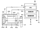
- FIG. 1 is an overall configuration diagram showing a brake system having an electric brake device according to an embodiment of the present invention. It is sectional drawing which expands and shows the electric brake device, the master pressure control unit, etc. in FIG.
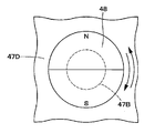
- FIG. 3 is a side view of the sensor magnet of the electric brake device in FIG. 2 as viewed from the direction of arrows III-III.
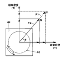
- It is a characteristic diagram which shows an example of the relationship between the magnetic flux density and magnetic flux vector of a sensor magnet detected with an electric motor rotational position sensor.
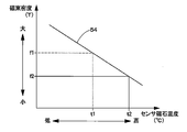
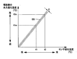
- It is a characteristic diagram which shows the correlation with the magnetic flux density of a sensor magnet, and the temperature of a sensor magnet.
- left and right front wheels 1L and 1R and left and right rear wheels 2L and 2R are provided below a vehicle body (not shown) constituting a vehicle body.
- the left and right front wheels 1L and 1R are respectively provided with front wheel side wheel cylinders 3L and 3R
- the left and right rear wheels 2L and 2R are respectively provided with rear wheel side wheel cylinders 4L and 4R.
- These wheel cylinders 3L, 3R, 4L, 4R constitute a hydraulic disc brake or drum brake cylinder, and apply braking force to each wheel (front wheels 1L, 1R and rear wheels 2L, 2R). It is.
- the brake pedal 5 is provided on the front board (not shown) side of the vehicle body.
- the brake pedal 5 is depressed by the driver in the direction of arrow A in FIG. 1 when the vehicle is braked.
- the brake pedal 5 is provided with an operation amount detector 6.
- the operation amount detector 6 detects a depression operation amount (stroke amount) or a depression force of the brake pedal 5 and outputs a detection signal to a wheel pressure control unit 45, a master pressure control unit 50, and the like which will be described later.
- brake fluid pressure is generated in the master cylinder 7 via an electric booster 15 described later.
- the master cylinder 7 has a bottomed cylindrical cylinder body 8 that is closed with one side being an open end and the other side being a bottom.
- the cylinder body 8 is provided with first and second supply ports 8A and 8B communicating with the inside of the reservoir 13.
- the first supply port 8A communicates with and is blocked from the first hydraulic chamber 10A by a sliding displacement of a booster piston 17 described later.
- the second supply port 8B is communicated with and blocked from the second hydraulic chamber 10B by the second piston 9.
- the first return spring 11 is located between the booster piston 17 and the second piston 9 in the first hydraulic pressure chamber 10 ⁇ / b> A, and the booster piston 17 faces the opening end side of the cylinder body 8. Is energized.
- the second return spring 12 is located in the second hydraulic pressure chamber 10B and is disposed between the bottom of the cylinder body 8 and the second piston 9, and the second piston 9 is connected to the first hydraulic pressure. Energizing toward the chamber 10A side.
- an electric booster 15 is provided as a booster for increasing the operating force of the brake pedal 5 and as a brake device.
- the electric booster 15 variably controls the brake fluid pressure generated in the master cylinder 7 by driving and controlling an electric actuator 19 described later based on the output of the operation amount detector 6.
- the electric booster 15 is provided with a booster housing 16 fixed to a vehicle front wall (not shown), which is a front board of the vehicle body, and a movably provided booster housing 16 for an input rod 18 described later. And a booster piston 17 as a relatively movable piston, and an electric actuator 19 (described later) for moving the booster piston 17 forward and backward in the axial direction of the master cylinder 7 and applying a booster thrust to the booster piston 17. Yes.
- the booster housing 16 is provided between a cylindrical speed reducer case 16A that accommodates a speed reduction mechanism 21 and the like to be described later, and the speed reducer case 16A and the cylinder body 8 of the master cylinder 7.
- the booster piston 17 is disposed in the axial direction.
- a cylindrical support case 16B supported so as to be slidably displaceable, and the support case 16B across the reduction gear case 16A are arranged on the opposite side (one side in the axial direction) of the reduction gear case 16A.
- a stepped cylindrical lid 16C that closes the opening on the side.
- a support plate 16D for fixedly supporting an electric motor 47 described later is provided on the outer peripheral side of the reduction gear case 16A.
- the electric actuator 19 of the electric booster 15 includes an electric motor 47 (described later) provided on a reduction gear case 16A of the booster housing 16 via a support plate 16D, and the rotation of the electric motor 47 is reduced to reduce the rotation of the electric motor 47.
- a speed reduction mechanism 21 such as a belt for transmitting to the cylindrical rotating body 20 and a linear motion mechanism 22 such as a ball screw for converting the rotation of the cylindrical rotating body 20 into the axial displacement (advance and retreat movement) of the booster piston 17 are configured.
- the electric motor 47 operates the booster piston 17 of the master cylinder 7 in accordance with the operation of the brake pedal 5.
- the linear motion mechanism 22 converts the rotational torque of the electric motor 47 into the propulsive force of the booster piston 17 and is configured as a torque conversion mechanism of the present invention.
- the electric motor 47 is connected to a master pressure control unit 50 which will be described later, and is controlled by the master pressure control unit 50.
- the electric motor 47 and the master pressure control unit 50 constitute an electric motor control device of the present invention.
- the electric motor 47 and the master pressure control unit 50 will be described in detail later.
- a return spring 23 that constantly urges the booster piston 17 in the braking release direction (the direction indicated by the arrow B in FIG. 1).
- the booster piston 17 is returned in the direction of arrow B to the initial position shown in FIG. 1 by the driving force when the motor 47 is rotated in the reverse direction and the urging force of the return spring 23 when the brake operation is released.
- the hydraulic pressure sensor 24 detects the brake hydraulic pressure of the master cylinder 7.
- the hydraulic pressure sensor 24 detects, for example, the hydraulic pressure in the cylinder side hydraulic pipe 14A, and detects the brake hydraulic pressure supplied from the master cylinder 7 to the ESC 25 described later via the cylinder side hydraulic pipe 14A.
- the hydraulic pressure sensor 24 is electrically connected to a wheel pressure control unit 45 to be described later, and a detection signal from the hydraulic pressure sensor 24 is also transmitted from the wheel pressure control unit 45 to the master pressure control unit 50 via a signal line 46. Sent by communication.
- the hydraulic pressure supply device 25 as an ESC is provided between the wheel cylinders 3L, 3R, 4L, 4R and the master cylinder 7 provided on the respective wheels (front wheels 1L, 1R and rear wheels 2L, 2R) side of the vehicle. It has been.
- the hydraulic pressure supply device 25 variably controls the brake hydraulic pressure generated in the master cylinder 7 (first and second hydraulic pressure chambers 10A and 10B) by the electric booster 15 as the wheel cylinder pressure for each wheel.
- the wheel cylinder pressure control device is configured to be individually supplied to the wheel cylinders 3L, 3R, 4L, and 4R of each wheel.
- the hydraulic pressure supply device 25 performs various types of brake control (for example, braking force distribution control for distributing braking force to the front wheels 1L and 1R, the rear wheels 2L and 2R, antilock brake control, vehicle stabilization control, etc.).
- brake control for example, braking force distribution control for distributing braking force to the front wheels 1L and 1R, the rear wheels 2L and 2R, antilock brake control, vehicle stabilization control, etc.
- necessary brake hydraulic pressure is supplied from the master cylinder 7 to the wheel cylinders 3L, 3R, 4L, 4R via the cylinder side hydraulic pipes 14A, 14B and the like.
- the hydraulic pressure supply device 25 supplies the hydraulic pressure output from the master cylinder 7 (first and second hydraulic pressure chambers 10A and 10B) via the cylinder side hydraulic pressure pipes 14A and 14B to the brake side piping section. Distribution and supply to the wheel cylinders 3L, 3R, 4L and 4R via 26A, 26B, 26C and 26D. As a result, independent braking forces are individually applied to the wheels (front wheels 1L, 1R, rear wheels 2L, 2R).
- the hydraulic pressure supply device 25 includes control valves 31, 31 ′, 32, 32 ′, 33, 33 ′, 36, 36 ′, 37, 37 ′, 44, 44 ′ described later, and hydraulic pumps 38, 38 ′. Is configured to include a hydraulic pressure control reservoir 43, 43 'and the like.
- the hydraulic pressure supply device 25 is connected to one output port of the master cylinder 7 (that is, the cylinder-side hydraulic pipe 14A), and the wheel cylinder 3L on the left front wheel (FL) side and the wheel cylinder on the right rear wheel (RR) side.
- the first hydraulic system 27 for supplying hydraulic pressure to 4R and the other output port (that is, the cylinder side hydraulic pipe 14B) are connected to the right front wheel (FR) side wheel cylinder 3R and the left rear wheel (RL).
- the first hydraulic system 27 and the second hydraulic system 27 ' have the same configuration, the following description will be given only for the first hydraulic system 27, and the second hydraulic system 27'.
- “′” is given to the reference numerals of the respective constituent elements, and the description thereof is omitted.
- the first hydraulic system 27 of the hydraulic pressure supply device 25 includes a brake pipe 28 connected to the tip side of the cylinder side hydraulic pipe 14A.
- the brake pipe 28 includes a first pipe section 29 and a second pipe line 28.
- the two branch portions 30 are connected to the wheel cylinders 3L and 4R, respectively.
- the brake pipe line 28 and the first pipe line part 29 constitute a pipe line that supplies the hydraulic pressure to the wheel cylinder 3L together with the brake side pipe part 26A, and the brake pipe line 28 and the second pipe line part 30 constitute the brake side pipe.
- a pipe 26 that supplies hydraulic pressure to the wheel cylinder 4R is configured together with the portion 26D.
- the brake conduit 28 is provided with a brake hydraulic pressure supply control valve 31, and the supply control valve 31 is a normally-open electromagnetic switching valve that opens and closes the brake conduit 28.
- the first pipe section 29 is provided with a pressure increase control valve 32, and the pressure increase control valve 32 is constituted by a normally open electromagnetic switching valve that opens and closes the first pipe section 29.
- the second pipe section 30 is provided with a pressure increase control valve 33, and the pressure increase control valve 33 is a normally open electromagnetic switching valve that opens and closes the second pipe section 30.
- the first hydraulic system 27 of the hydraulic pressure supply device 25 includes first and second pressure reducing pipes 34 and 35 that connect the wheel cylinders 3L and 4R and the hydraulic pressure control reservoir 43, respectively.
- the pressure reducing pipes 34 and 35 are provided with first and second pressure reducing control valves 36 and 37, respectively.
- the first and second pressure reduction control valves 36 and 37 are normally closed electromagnetic switching valves that open and close the pressure reduction lines 34 and 35, respectively.
- the hydraulic pressure supply device 25 includes a hydraulic pressure pump 38 as a hydraulic pressure generating means that is a hydraulic pressure source, and the hydraulic pressure pump 38 is rotationally driven by an electric motor 39.
- the electric motor 39 is driven by the power supply from the wheel pressure control unit 45, and stops rotating together with the hydraulic pump 38 when the power supply is stopped.
- the discharge side of the hydraulic pump 38 is positioned downstream of the supply control valve 31 in the brake line 28 via the check valve 40 (that is, the first line part 29 and the second line part 30 Is connected to the position where the The suction side of the hydraulic pump 38 is connected to a hydraulic pressure control reservoir 43 via check valves 41 and 42.
- the hydraulic pressure control reservoir 43 is provided to temporarily store excess brake fluid, and is not limited to the ABS control of the brake system (hydraulic pressure supply device 25), but also during other brake control, the wheel cylinders 3L, Excess brake fluid flowing out from a 4R cylinder chamber (not shown) is temporarily stored. Further, the suction side of the hydraulic pump 38 is connected to the cylinder side hydraulic pipe 14A (that is, the brake pipe 28 of the master cylinder 7) via a check valve 41 and a pressurization control valve 44 that is a normally closed electromagnetic switching valve. Of these, it is connected to the upstream side of the supply control valve 31.
- the wheel pressure control unit 45 is a hydraulic pressure supply controller that electrically drives and controls the hydraulic pressure supply device 25.
- the wheel pressure control unit 45 is connected at its input side to a hydraulic pressure sensor 24, a signal line 46, a vehicle data bus (not shown), and the like.
- the output side of the wheel pressure control unit 45 includes control valves 31, 31 ', 32, 32', 33, 33 ', 36, 36', 37, 37 ', 44, 44', an electric motor 39, and a signal line 46. And a vehicle data bus or the like.
- the electric motor 47 is configured using, for example, a DC brushless motor.
- the electric motor 47 is connected to a master pressure control unit 50 which will be described later, and operates according to a command from the master pressure control unit 50.
- the electric motor 47 extends in a cylindrical casing 47A fixed to the support plate 16D, and substantially parallel to the input rod 18 at the center of the casing 47A (left and right directions in FIG. 1 and FIG. 2).
- the rotary shaft 47B includes a stator 47C provided in the casing 47A, and a rotor 47D that is located on the inner peripheral side of the stator 47C and is fixed to the rotary shaft 47B and includes a permanent magnet.
- a motor rotation position sensor 49 described later is provided on the bottom 47A1 of the casing 47A.
- the rotating shaft 47B is formed using, for example, a metal material with good thermal conductivity.
- One end side of the rotating shaft 47B penetrates the support plate 16D and is connected to the speed reduction mechanism 21 (drive pulley thereof).
- the other end side of the rotating shaft 47B extends toward the bottom 47A1 of the casing 47A, and a sensor magnet 48 described later is provided.
- the sensor magnet 48 is located in the casing 47A and provided on the other end side of the rotating shaft 47B. As shown in FIG. 3, the sensor magnet 48 is composed of, for example, a dipole magnet having N and S poles separated in the radial direction. By rotating together with the rotating shaft 47B, the magnetic flux produced by the sensor magnet 48 also rotates. It is the composition to do.
- the sensor magnet 48 is metal touched on the rotating shaft 47B of the electric motor 47 at the center. That is, the sensor magnet 48 is directly fixed (contacted) to the electric motor 47 (rotating shaft 47B). As a result, the heat generated by the electric motor 47 is transmitted to the sensor magnet 48 through the rotating shaft 47B more efficiently than heat conduction by air. In other words, when the sensor magnet 48 is metal-touched to the rotation shaft 47B, the temperature of the permanent magnet of the rotor 47D fixed to the rotation shaft 47B and the temperature of the sensor magnet 48 are approximated or the correlation becomes clear. I have to.
- the motor rotation position sensor 49 is provided in the bottom 47A1 of the casing 47A at a position that is located in the casing 47A and faces the sensor magnet 48. As shown in FIG. 4, the motor rotational position sensor 49 detects, for example, the magnetic flux density in two directions perpendicular to the axial direction of the rotating shaft 47B out of the magnetic flux density of the sensor magnet 48. It constitutes a density detection means.
- the motor rotation position sensor 49 includes a sensor element (not shown) that detects the magnetic flux density of the sensor magnet 48 that rotates as the rotating shaft 47B of the motor 47 rotates.
- the electric motor rotation position sensor 49 calculates the vector angle ⁇ from the magnetic flux density of the sensor magnet 48 detected by the sensor element, and detects the rotation position of the rotation shaft 47B of the electric motor 47.
- the motor rotational position sensor 49 measures the magnitudes (f1, f2) of the vectors F1, F2 obtained by combining the magnetic flux densities in the two directions of the sensor magnet 48.
- the rotational position of the rotating shaft 47B and the magnitudes (f1, f2) of the vectors F1, F2 are transmitted to the master pressure control unit 50 described later.
- the master pressure control unit 50 (ECU) is composed of a microcomputer, for example, and constitutes a control device of the present invention.
- the master pressure control unit 50 electrically drives and controls the electric actuator 19 (electric motor 47) of the electric booster 15.
- the master pressure control unit 50 includes a memory 51, a temperature estimation unit 52, and an electric motor control unit 53.
- the input side of the master pressure control unit 50 is connected to an operation amount detector 6 for detecting an operation amount or a pedaling force of the brake pedal 5, an electric motor 47, and an in-vehicle signal line 46 capable of communication called L-CAN, for example.
- the master pressure control unit 50 is connected to a vehicle data bus (not shown) that transmits and receives signals from a control unit (ECU) of another vehicle device (not shown). Further, the output side of the master pressure control unit 50 is connected to an electric motor 47, a vehicle signal line 46, a vehicle data bus, and the like.
- the master pressure control unit 50 variably controls the brake hydraulic pressure generated in the master cylinder 7 by the electric actuator 19 in accordance with detection signals from the operation amount detector 6 and the hydraulic pressure sensor 24, and the electric booster 15 It also has a function of determining whether or not is operating normally.
- the master pressure control unit 50 controls (feedback control) the electric motor 47 (that is, the booster piston 17) according to the rotational position of the electric motor rotational position sensor 49.
- the input rod 18 moves forward into the cylinder body 8 of the master cylinder 7, and the movement at this time is detected by the operation amount detector 6. .
- the electric motor control unit 53 of the master pressure control unit 50 outputs an activation command to the electric motor 47 by the detection signal from the operation amount detector 6 to drive the electric motor 47 to rotate. Then, the rotation is transmitted to the cylindrical rotating body 20 via the speed reduction mechanism 21, and the rotation of the cylindrical rotating body 20 is converted into the axial displacement of the booster piston 17 by the linear motion mechanism 22.
- the booster piston 17 moves forward integrally with the input rod 18 (or with relative displacement) toward the cylinder body 8 of the master cylinder 7, and a pedaling force (thrust force) applied to the input rod 18 from the brake pedal 5.
- the booster thrust applied from the electric actuator 19 to the booster piston 17 is generated in the first and second hydraulic chambers 10A and 10B of the master cylinder 7.
- the master pressure control unit 50 can monitor the hydraulic pressure generated in the master cylinder 7 by receiving the detection signal from the hydraulic pressure sensor 24 from the signal line 46, and the electric booster 15 operates normally. It can be determined whether or not.
- the master pressure control unit 50 estimates the temperature of the electric motor 47 and controls the electric motor 47. That is, the master pressure control unit 50 may operate the electric motor 47 with a current exceeding the rating in order to cause the electric motor 47 to temporarily output a large output. In this case, the master pressure control unit 50 monitors the temperature of the permanent magnet of the electric motor 47 in order to suppress demagnetization and overheating of the permanent magnet provided in the rotor 47D.
- the memory 51 of the master pressure control unit 50 for example, the magnitudes (f1, f2) of the magnetic flux vectors F1, F2 of the sensor magnet 48 and the temperatures (t1, t2) of the sensor magnet 48 as shown in FIG. ) And a characteristic diagram showing the correlation between the temperature (t1, t2) of the sensor magnet 48 and the temperature (t1a, t2a) of the permanent magnet of the motor 47 as shown in FIG. Is stored.
- the memory 51 may store experimental formulas obtained experimentally instead of the characteristic diagrams as shown in FIGS.
- the correlation between the temperature (t1, t2) of the sensor magnet 48 and the temperature (t1a, t2a) of the motor 47 as shown in FIG. 6 is based on the composition of the sensor magnet 48 and the permanent magnet of the motor 47. It can be obtained analytically or experimentally.
- the temperature estimation unit 52 Based on the characteristic line 54 of FIG. 5 stored in the memory 51 from the magnitudes (f1, f2) of the vectors F1, F2 of the sensor magnet 48 transmitted from the electric motor rotational position sensor 49, the temperature estimation unit 52 The temperature (t1, t2) of the magnet 48 is estimated (calculated). Next, the temperature estimation unit 52 calculates the temperature (t1a, t2a) of the permanent magnet provided in the rotor 47D of the electric motor 47 from the temperature (t1, t2) of the sensor magnet 48 based on the characteristic line 55 of FIG. Estimate (calculate). In this case, the temperature estimation part 52 comprises the temperature estimation means of this invention.
- the electric motor control unit 53 of the master pressure control unit 50 controls the drive current so that the electric motor 47 does not overheat based on the estimated temperature of the permanent magnet of the electric motor 47, or sets the target according to the temperature characteristics of the electric motor 47. To control the drive current optimal for the motor output.
- the motor control unit 53 constitutes the motor control means of the present invention.
- the electric brake device including the motor control device according to the present embodiment has the above-described configuration, and the operation thereof will be described next.
- the master pressure control unit 50 outputs a start command to the electric motor 47 by a detection signal from the operation amount detector 6 to rotationally drive the electric motor 47, and the rotation is transmitted to the cylindrical rotating body 20 via the speed reduction mechanism 21.
- the rotation of the cylindrical rotating body 20 is converted into the axial displacement of the booster piston 17 by the linear motion mechanism 22.
- the booster piston 17 of the electric booster 15 advances substantially integrally with the input rod 18 toward the cylinder body 8 of the master cylinder 7, and a pedaling force (thrust force) applied to the input rod 18 from the brake pedal 5.
- the booster thrust applied from the electric actuator 19 to the booster piston 17 is generated in the first and second hydraulic chambers 10A and 10B of the master cylinder 7.
- the master pressure control unit 50 receives the detection signal from the hydraulic pressure sensor 24 from the signal line 46 to monitor the hydraulic pressure generated in the master cylinder 7, and the electric actuator 19 (of the electric motor 47 of the electric motor 47).
- the rotation of the rotation shaft 47B is feedback-controlled.
- the master pressure control unit 50 variably controls the brake fluid pressure generated in the first and second fluid pressure chambers 10A and 10B of the master cylinder 7 based on the depression operation amount of the brake pedal 5. Can do.
- the master pressure control unit 50 can determine whether or not the electric booster 15 is operating normally according to the detection values of the operation amount detector 6 and the hydraulic pressure sensor 24.
- the input rod 18 connected to the brake pedal 5 receives the pressure in the first hydraulic chamber 10A and transmits it to the brake pedal 5 as a brake reaction force.
- the driver of the vehicle is given a response through the input rod 18, thereby improving the operational feeling of the brake pedal 5 and maintaining a good pedal feeling.
- the electric motor 47 may be operated with a current exceeding the rating. If the electric motor 47 is operated with a current exceeding the rating, the electric motor 47 may increase in temperature. Therefore, the master pressure control unit 50 monitors the temperature of the electric motor 47 or the temperature of the permanent magnet of the electric motor 47 in order to suppress demagnetization and overheating of the permanent magnet provided in the rotor 47D accompanying the temperature rise of the electric motor 47. There is a need.
- the temperature of the motor is estimated based on the current value of the motor without using a dedicated temperature sensor for the motor, thereby saving space and reducing costs.
- the temperature of the motor is estimated based on the current value of the motor, it is easily affected by disturbance such as heat radiation, and there is a possibility that an error between the actual temperature of the motor and the estimated temperature becomes large.
- the magnetic flux density of the sensor magnet 48 is detected using the motor rotation position sensor 49 of the motor 47.
- the master pressure control unit 50 estimates the temperature from the magnetic flux density of the sensor magnet 48 and estimates the temperature of the permanent magnet of the electric motor 47 based on the correlation between the temperature of the sensor magnet 48 and the temperature of the permanent magnet of the electric motor 47. To do.
- temperature estimation control of the permanent magnet of the electric motor 47 performed by the master pressure control unit 50 will be described. Note that the temperature estimation control of the permanent magnet is repeatedly executed at predetermined intervals while the electric motor 47 is driven, for example.
- the sensor element of the electric motor rotational position sensor 49 has a density of magnetic flux flowing from the sensor magnet 48 metal-touched to the other end side of the rotating shaft 47B of the electric motor 47 ( Magnetic flux density) is detected.
- the sensor element detects the magnetic flux density in two directions perpendicular to the rotation shaft 47 ⁇ / b> B output from the sensor magnet 48.
- the motor rotational position sensor 49 combines the magnetic flux densities in the two directions to calculate the magnitude f1 and vector angle ⁇ of the magnetic flux vector F1, and transmits them to the master pressure control unit 50. .
- the temperature estimation unit 52 of the master pressure control unit 50 calculates the temperature t1 of the sensor magnet 48 corresponding to the magnitude f1 of the magnetic flux vector F1 from the characteristic line 54 of FIG. Next, the temperature estimation unit 52 calculates the temperature t1a of the permanent magnet of the electric motor 47 corresponding to the temperature t1 of the sensor magnet 48 from the characteristic line 55 of FIG. In this case, the estimated temperature t1a of the permanent magnet must be considered between the actual temperature of the permanent magnet and the influence of disturbance due to the ambient temperature, for example.
- the sensor magnet 48 is fixed to the rotating shaft 47B of the electric motor 47 with a metal touch, that is, directly to the rotating shaft 47B.
- the sensor magnet 48 and the stator 47C and the rotor 47D (permanent magnet) of the electric motor 47 are arranged as close as possible.
- the influence range C of the disturbance due to the ambient temperature can be made so small that it can be ignored. Therefore, the estimated temperature t1a of the permanent magnet is regarded as the actual temperature of the permanent magnet. Can do.
- the electric motor rotational position sensor 49 calculates a magnetic flux vector F2 having a magnitude f2 (f2 ⁇ f1).
- the temperature estimation unit 52 of the master pressure control unit 50 calculates the temperature t2 (t2> t1) of the sensor magnet 48 corresponding to the magnitude f2 of the magnetic flux vector F2. Then, the temperature estimation unit 52 calculates the temperature t2a (t2a> t1a) of the permanent magnet of the electric motor 47 corresponding to the temperature t2 of the sensor magnet 48. Thereby, the master pressure control unit 50 can determine that the temperature of the electric motor 47 (its permanent magnet) is rising.
- the estimated temperature t2a of the permanent magnet is, for example, a threshold for drive control of the electric motor 47. That is, when the temperature estimation unit 52 calculates the temperature t2a or higher, the motor control unit 53 of the master pressure control unit 50 limits the drive current so that the motor 47 does not overheat, or according to the temperature characteristics of the motor 47. To control the optimum drive current for the target motor output.
- the magnetic flux density of the sensor magnet 48 that rotates with the rotation of the rotating shaft 47B of the electric motor 47 is detected, and the temperature of the electric motor 47 is estimated based on this detected value.
- the magnitude of the magnetic flux density varies depending on the temperature of the sensor magnet 48. That is, when the temperature of the sensor magnet 48 rises, the magnetic flux density emitted from the sensor magnet 48 decreases, and accordingly, the magnitude of the magnetic flux vector also decreases.
- the temperature of the electric motor 47 (permanent magnet) can be measured with less influence of disturbance.
- the magnetic flux density of the sensor magnet 48 is detected by an electric motor rotational position sensor 49 that detects the rotational position of the rotary shaft 47B of the electric motor 47. That is, the magnetic flux density of the sensor magnet 48 is detected using the existing motor rotation position sensor 49 without using a new sensor. Further, the motor rotation position sensor 49 measures the magnitude of a vector obtained by combining the magnetic flux densities in the two directions of the sensor magnet 48. Thereby, size reduction and cost reduction of the electric motor 47 can be achieved.
- the sensor magnet 48 is metal touched to the rotating shaft 47B of the electric motor 47. That is, it is directly fixed to the rotating shaft 47B. Therefore, the heat generated by the electric motor 47 is transmitted in inverse proportion to the distance between the stator 47C and the rotor 47D (permanent magnet) and the sensor magnet 48. Therefore, by arranging the sensor magnet 48, the stator 47C of the electric motor 47, and the rotor 47D (permanent magnet) as close as possible, the influence of the disturbance due to the ambient temperature can be reduced. The influence can be minimized.
- the temperature estimation unit 52 as temperature estimation means for estimating the temperature of the electric motor 47 is provided in the master pressure control unit 50 has been described as an example.
- the present invention is not limited to this.
- a temperature estimation unit may be provided in the motor rotation position sensor 49 serving as a magnetic flux density detection unit, and a temperature estimation unit may be provided in another control unit to calculate the estimated temperature of the motor 47. May be.
- the present invention is not limited to this.
- the case where the motor rotation position sensor 49 that detects the magnetic flux density in two directions of the sensor magnet 48 is used has been described as an example.
- the present invention is not limited to this.
- an electric motor rotation position sensor that detects magnetic flux density in three or more directions may be used.
- the case where a two-pole magnet is used as the sensor magnet has been described as an example.
- the present invention is not limited to this.
- a multipolar magnet in which a plurality of N poles and S poles are arranged in the circumferential direction may be used as the sensor magnet.
- the motor control device is applied to an electric brake device used in a vehicle such as a four-wheel vehicle.
- an electric disc brake or other vehicle device disposed on a wheel as an electric brake device, for example. It can be used for various electric actuators using an electric motor such as an electric power steering device or an electric actuator other than a vehicle device.
- an electric motor A sensor magnet that rotates with rotation of the rotating shaft of the electric motor; Magnetic flux density detection means for detecting the magnetic flux density of the sensor magnet; Temperature estimation means for estimating the temperature of the electric motor based on the detection value of the magnetic flux density detection means; Electric motor control means for controlling the electric motor according to the estimated temperature of the temperature estimation means.
- the magnetic flux density detecting means is an electric motor rotational position sensor that detects a rotational position of a rotating shaft of the electric motor from the detected magnetic flux density.
- the temperature estimation means estimates the temperature of the sensor magnet from the magnetic flux density of the sensor magnet, and the temperature of the sensor magnet and the permanent of the motor.
- the temperature of the permanent magnet of the motor is estimated based on the correlation with the temperature of the magnet.
- the magnetic flux density detecting means measures a magnitude of a vector obtained by combining magnetic flux densities in at least two directions of the sensor magnet.
- the sensor magnet is directly fixed to the rotating shaft of the electric motor.
- an electric motor that operates the piston of the master cylinder according to the operation of the brake pedal;
- a torque conversion mechanism that converts rotational torque of the electric motor into propulsive force of the piston;
- An electric motor rotation position sensor that detects a rotation position of the rotation shaft of the electric motor from a sensor element that detects a magnetic flux density of a sensor magnet that rotates with rotation of the rotation shaft of the electric motor;
- An electric brake device comprising: a control device that controls the electric motor in accordance with the rotational position detected by the electric motor rotational position sensor;
- the control device includes: Temperature estimation means for estimating the temperature of the motor from the magnetic flux density of the sensor magnet detected from the sensor element of the motor rotation position sensor, and motor control means for controlling the motor according to the estimated temperature of the temperature estimation means With.
Landscapes
- Engineering & Computer Science (AREA)
- Power Engineering (AREA)
- Microelectronics & Electronic Packaging (AREA)
- Braking Systems And Boosters (AREA)
Abstract
小さい誤差で永久磁石の温度を推定することができる電動機の制御装置および電動ブレーキ装置を提供する。 電動機の制御装置は、電動機47と、電動機47の回転軸47Bの回転に伴って回転するセンサ磁石48と、センサ磁石48の磁束密度を検知する電動機回転位置センサ49と、電動機回転位置センサ49の検知値に基づいて電動機47の温度を推定する温度推定部52と、温度推定部52の推定温度に応じて電動機47を制御する電動機制御部53とを備えている。
Description
本発明は、例えば種々の電動アクチュエータに用いられる電動機の制御装置および四輪自動車等の車両に用いられる電動ブレーキ装置に関する。
電動アクチュエータに用いられる電動機では、例えば定格を超える電流で動作させた場合での電動機(モータ)の永久磁石の減磁および過熱等を抑制するために、永久磁石の温度を監視する必要がある。この場合、電動機周りの配線の省スペース化およびコストを低減するために、温度センサを用いることなく電動機の永久磁石の温度を推定している。具体的には、電動機の電流値から永久磁石の温度を推定している(例えば、特許文献1参照)。
しかし、電流値から温度を推定する場合、放熱等の外乱に伴う誤差が大きくなる虞がある。
本発明は、上述した従来技術の問題に鑑みなされたもので、本発明の目的は、小さい誤差で電動機(の永久磁石)の温度を推定することができる電動機の制御装置および電動ブレーキ装置を提供することにある。
上述した課題を解決するため、本発明の電動機の制御装置は、電動機と、前記電動機の回転軸の回転に伴って回転するセンサ磁石と、前記センサ磁石の磁束密度を検知する磁束密度検知手段と、前記磁束密度検知手段の検知値に基づいて前記電動機の温度を推定する温度推定手段と、前記温度推定手段の推定温度に応じて前記電動機を制御する電動機制御手段とを備えたことを特徴としている。
また、本発明の電動ブレーキ装置は、ブレーキペダルの操作に応じてマスタシリンダのピストンを作動させる電動機と、前記電動機の回転トルクを前記ピストンの推進力に変換するトルク変換機構と、前記電動機の回転軸の回転に伴って回転するセンサ磁石の磁束密度を検知するセンサ素子から前記電動機の前記回転軸の回転位置を検出する電動機回転位置センサと、前記電動機回転位置センサが検出する前記回転位置に応じて前記電動機を制御する制御装置と、を備えた電動ブレーキ装置において、前記制御装置は、前記電動機回転位置センサの前記センサ素子から検知される前記センサ磁石の磁束密度から前記電動機の温度を推定する温度推定手段と、該温度推定手段の推定温度に応じて前記電動機を制御する電動機制御手段とを備えたことを特徴としている。
本発明によれば、電動機の推定温度の誤差を小さくすることにより、電動機の制御装置および電動ブレーキ装置の信頼性、安定性を向上することができる。
以下、本発明の実施の形態による電動機の制御装置を四輪自動車に搭載される電動ブレーキ装置に用いた場合を例に挙げて、図1ないし図6に従って詳細に説明する。
図1において、左,右の前輪1L,1Rと左,右の後輪2L,2Rとは、車両のボディを構成する車体(図示せず)の下側に設けられている。左,右の前輪1L,1Rには、それぞれ前輪側ホイールシリンダ3L,3Rが設けられ、左,右の後輪2L,2Rには、それぞれ後輪側ホイールシリンダ4L,4Rが設けられている。これらのホイールシリンダ3L,3R、4L,4Rは、液圧式のディスクブレーキまたはドラムブレーキのシリンダを構成し、夫々の車輪(前輪1L,1Rおよび後輪2L,2R)毎に制動力を付与するものである。
ブレーキペダル5は、車体のフロントボード(図示せず)側に設けられている。このブレーキペダル5は、車両のブレーキ操作時に運転者によって図1中の矢示A方向に踏込み操作される。ブレーキペダル5には、操作量検出器6が設けられている。この操作量検出器6は、ブレーキペダル5の踏込み操作量(ストローク量)または踏力を検出し、その検出信号を後述のホイール圧制御ユニット45、マスタ圧制御ユニット50等に出力する。ブレーキペダル5が踏込み操作されると、マスタシリンダ7には後述の電動倍力装置15を介してブレーキ液圧が発生する。
マスタシリンダ7は、一側が開口端となり他側が底部となって閉塞された有底筒状のシリンダ本体8を有している。このシリンダ本体8には、リザーバ13内に連通する第1,第2のサプライポート8A,8Bが設けられている。第1のサプライポート8Aは、後述するブースタピストン17の摺動変位により第1の液圧室10Aに対して連通,遮断される。一方、第2のサプライポート8Bは、第2のピストン9により第2の液圧室10Bに対して連通,遮断される。
第1の戻しばね11は、第1の液圧室10A内に位置してブースタピストン17と第2のピストン9との間に配設され、ブースタピストン17をシリンダ本体8の開口端側に向けて付勢している。第2の戻しばね12は、第2の液圧室10B内に位置してシリンダ本体8の底部と第2のピストン9との間に配設され、第2のピストン9を第1の液圧室10A側に向けて付勢している。
車両のブレーキペダル5とマスタシリンダ7との間には、ブレーキペダル5の操作力を増大させるブースタとして、また、ブレーキ装置としての電動倍力装置15が設けられている。この電動倍力装置15は、操作量検出器6の出力に基づいて後述の電動アクチュエータ19を駆動制御することにより、マスタシリンダ7内に発生するブレーキ液圧を可変に制御するものである。
電動倍力装置15は、車体のフロントボードである車室前壁(図示せず)に固定して設けられるブースタハウジング16と、該ブースタハウジング16に移動可能に設けられ後述の入力ロッド18に対して相対移動可能なピストンとしてのブースタピストン17と、該ブースタピストン17をマスタシリンダ7の軸方向に進退移動させ当該ブースタピストン17にブースタ推力を付与する後述の電動アクチュエータ19とを含んで構成されている。
ブースタハウジング16は、後述の減速機構21等を内部に収容する筒状の減速機ケース16Aと、該減速機ケース16Aとマスタシリンダ7のシリンダ本体8との間に設けられブースタピストン17を軸方向に摺動変位可能に支持した筒状の支持ケース16Bと、減速機ケース16Aを挟んで支持ケース16Bとは軸方向の反対側(軸方向一側)に配置され減速機ケース16Aの軸方向一側の開口を閉塞する段付筒状の蓋体16Cとにより構成されている。減速機ケース16Aの外周側には、後述の電動機47を固定的に支持するための支持板16Dが設けられている。
電動倍力装置15の電動アクチュエータ19は、ブースタハウジング16の減速機ケース16Aに支持板16Dを介して設けられた後述の電動機47と、該電動機47の回転を減速して減速機ケース16A内の筒状回転体20に伝えるベルト等の減速機構21と、筒状回転体20の回転をブースタピストン17の軸方向変位(進退移動)に変換するボールネジ等の直動機構22とにより構成されている。電動機47は、ブレーキペダル5の操作に応じてマスタシリンダ7のブースタピストン17を作動させる。直動機構22は、電動機47の回転トルクをブースタピストン17の推進力に変換するもので、本発明のトルク変換機構として構成されている。
また、電動機47は、後述のマスタ圧制御ユニット50に接続され、該マスタ圧制御ユニット50により制御されている。そして、電動機47とマスタ圧制御ユニット50とにより本発明の電動機の制御装置を構成している。電動機47とマスタ圧制御ユニット50とについては、後で詳細に説明する。
ブースタハウジング16の支持ケース16B内には、ブースタピストン17を制動解除方向(図1中の矢示B方向)に常時付勢する戻しばね23が設けられている。ブースタピストン17は、ブレーキ操作の解除時に電動機47が逆向きに回転されるときの駆動力と戻しばね23の付勢力とにより図1に示す初期位置まで矢示B方向に戻されるものである。
液圧センサ24は、マスタシリンダ7のブレーキ液圧を検出するものである。この液圧センサ24は、例えばシリンダ側液圧配管14A内の液圧を検出するもので、マスタシリンダ7からシリンダ側液圧配管14Aを介して後述のESC25に供給されるブレーキ液圧を検出する。液圧センサ24は、後述のホイール圧制御ユニット45に電気的に接続されると共に、液圧センサ24による検出信号は、ホイール圧制御ユニット45から信号線46を介してマスタ圧制御ユニット50にも通信により送られる。
ESCとしての液圧供給装置25は、車両の各車輪(前輪1L,1Rおよび後輪2L,2R)側に配設されたホイールシリンダ3L,3R、4L,4Rとマスタシリンダ7との間に設けられている。液圧供給装置25は、電動倍力装置15によりマスタシリンダ7(第1,第2の液圧室10A,10B)内に発生したブレーキ液圧を、車輪毎のホイールシリンダ圧として可変に制御して各車輪のホイールシリンダ3L,3R、4L,4Rに個別に供給するホイールシリンダ圧制御装置を構成している。
即ち、液圧供給装置25は、各種のブレーキ制御(例えば、前輪1L,1R、後輪2L,2R毎に制動力を配分する制動力配分制御、アンチロックブレーキ制御、車両安定化制御等)をそれぞれ行う場合に、必要なブレーキ液圧をマスタシリンダ7からシリンダ側液圧配管14A,14B等を介してホイールシリンダ3L,3R、4L,4Rに供給するものである。
ここで、液圧供給装置25は、マスタシリンダ7(第1,第2の液圧室10A,10B)からシリンダ側液圧配管14A,14Bを介して出力される液圧を、ブレーキ側配管部26A,26B,26C,26Dを介してホイールシリンダ3L,3R、4L,4Rに分配、供給する。これにより、車輪(前輪1L,1R、後輪2L,2R)毎にそれぞれ独立した制動力が個別に付与される。液圧供給装置25は、後述の各制御弁31,31′,32,32′,33,33′,36,36′,37,37′,44,44′と、液圧ポンプ38,38′を駆動する電動モータ39と、液圧制御用リザーバ43,43′等とを含んで構成されている。
液圧供給装置25は、マスタシリンダ7の一方の出力ポート(即ち、シリンダ側液圧配管14A)に接続されて左前輪(FL)側のホイールシリンダ3Lと右後輪(RR)側のホイールシリンダ4Rとに液圧を供給する第1液圧系統27と、他方の出力ポート(即ち、シリンダ側液圧配管14B)に接続されて右前輪(FR)側のホイールシリンダ3Rと左後輪(RL)側のホイールシリンダ4Lとに液圧を供給する第2液圧系統27′との2系統の液圧回路を備えている。ここで、第1液圧系統27と第2液圧系統27′とは同様な構成を有しているため、以下の説明は第1液圧系統27についてのみ行い、第2液圧系統27′については各構成要素の符号に「′」を付し、それぞれの説明を省略する。
液圧供給装置25の第1液圧系統27は、シリンダ側液圧配管14Aの先端側に接続されたブレーキ管路28を有し、ブレーキ管路28は、第1管路部29および第2管路部30の2つに分岐して、ホイールシリンダ3L,4Rにそれぞれ接続されている。ブレーキ管路28および第1管路部29は、ブレーキ側配管部26Aと共にホイールシリンダ3Lに液圧を供給する管路を構成し、ブレーキ管路28および第2管路部30は、ブレーキ側配管部26Dと共にホイールシリンダ4Rに液圧を供給する管路を構成している。
ブレーキ管路28には、ブレーキ液圧の供給制御弁31が設けられ、該供給制御弁31は、ブレーキ管路28を開,閉する常開の電磁切換弁により構成されている。第1管路部29には増圧制御弁32が設けられ、該増圧制御弁32は、第1管路部29を開,閉する常開の電磁切換弁により構成されている。第2管路部30には増圧制御弁33が設けられ、該増圧制御弁33は、第2管路部30を開,閉する常開の電磁切換弁により構成されている。
液圧供給装置25の第1液圧系統27は、ホイールシリンダ3L,4R側と液圧制御用リザーバ43とをそれぞれ接続する第1,第2の減圧管路34,35を有し、これらの減圧管路34,35には、それぞれ第1,第2の減圧制御弁36,37が設けられている。第1,第2の減圧制御弁36,37は、減圧管路34,35をそれぞれ開,閉する常閉の電磁切換弁により構成されている。
また、液圧供給装置25は、液圧源である液圧発生手段としての液圧ポンプ38を備え、該液圧ポンプ38は電動モータ39により回転駆動される。ここで、電動モータ39は、ホイール圧制御ユニット45からの給電により駆動され、給電停止時には液圧ポンプ38と一緒に回転停止される。液圧ポンプ38の吐出側は、逆止弁40を介してブレーキ管路28のうち供給制御弁31よりも下流側となる位置(即ち、第1管路部29と第2管路部30とが分岐する位置)に接続されている。液圧ポンプ38の吸込み側は、逆止弁41,42を介して液圧制御用リザーバ43に接続されている。
液圧制御用リザーバ43は、余剰のブレーキ液を一時的に貯留するために設けられ、ブレーキシステム(液圧供給装置25)のABS制御時に限らず、これ以外のブレーキ制御時にもホイールシリンダ3L,4Rのシリンダ室(図示せず)から流出してくる余剰のブレーキ液を一時的に貯留するものである。また、液圧ポンプ38の吸込み側は、逆止弁41および常閉の電磁切換弁である加圧制御弁44を介してマスタシリンダ7のシリンダ側液圧配管14A(即ち、ブレーキ管路28のうち供給制御弁31よりも上流側となる位置)に接続されている。
ホイール圧制御ユニット45(ECU)は、液圧供給装置25を電気的に駆動制御する液圧供給装置用コントローラである。このホイール圧制御ユニット45は、その入力側が、液圧センサ24、信号線46および車両データバス(図示せず)等に接続されている。ホイール圧制御ユニット45の出力側は、各制御弁31,31′,32,32′,33,33′,36,36′,37,37′,44,44′、電動モータ39、信号線46および車両データバス等に接続されている。
次に、電動アクチュエータ19の電動機47とマスタ圧制御ユニット50とについて説明する。
電動機47は、例えばDCブラシレスモータを用いて構成されている。この電動機47は、後述のマスタ圧制御ユニット50に接続され、マスタ圧制御ユニット50からの指令により作動する。そして、電動機47は、支持板16Dに固定された筒状のケーシング47Aと、該ケーシング47Aの中心部で入力ロッド18と略平行(図1、図2中の紙面の左,右方向)に延びる回転軸47Bと、ケーシング47A内に設けられたステータ47Cと、該ステータ47Cの内周側に位置して回転軸47Bに固着され永久磁石を備えたロータ47Dとを含んで構成されている。
ケーシング47Aの底部47A1には、後述の電動機回転位置センサ49が設けられている。回転軸47Bは、例えば熱伝導率のよい金属材料を用いて形成されている。回転軸47Bの一端側は、支持板16Dを貫通して減速機構21(の駆動プーリ)に接続されている。一方、回転軸47Bの他端側は、ケーシング47Aの底部47A1に向けて延び、後述のセンサ磁石48が設けられている。
センサ磁石48は、ケーシング47A内に位置して回転軸47Bの他端側に設けられている。図3に示すように、センサ磁石48は、例えば径方向にN極とS極とが分かれた2極磁石からなり、回転軸47Bと一緒に回転することにより、センサ磁石48の作る磁束も回転する構成となっている。
センサ磁石48は、中央部に電動機47の回転軸47Bがメタルタッチされている。即ち、センサ磁石48は、電動機47(回転軸47B)に直接的に固着(接触)されている。これにより、電動機47の発熱は、空気による熱伝導に比べて効率よく回転軸47Bを介してセンサ磁石48に伝達される。換言すれば、回転軸47Bにセンサ磁石48をメタルタッチさせることにより、回転軸47Bに固着されたロータ47Dの永久磁石の温度とセンサ磁石48の温度とが近似または、相関関係が明確になるようにしている。
電動機回転位置センサ49は、ケーシング47A内に位置してセンサ磁石48に対向する位置でケーシング47Aの底部47A1に設けられている。図4に示すように、電動機回転位置センサ49は、例えばセンサ磁石48の磁束密度のうち、回転軸47Bの軸方向に対して垂直な2方向の磁束密度を検出するもので、本発明の磁束密度検知手段を構成している。
電動機回転位置センサ49は、電動機47の回転軸47Bの回転に伴って回転するセンサ磁石48の磁束密度を検知するセンサ素子(図示せず)を備えている。電動機回転位置センサ49は、センサ素子で検知したセンサ磁石48の磁束密度からベクトル角αを算出して電動機47の回転軸47Bの回転位置を検出する。また、図4に示すように、電動機回転位置センサ49は、センサ磁石48の2方向の磁束密度を合成したベクトルF1,F2の大きさ(f1,f2)を計測する。回転軸47Bの回転位置およびベクトルF1,F2の大きさ(f1,f2)は、後述のマスタ圧制御ユニット50に送信される。
マスタ圧制御ユニット50(ECU)は、例えばマイクロコンピュータ等からなっており、本発明の制御装置を構成している。マスタ圧制御ユニット50は、電動倍力装置15の電動アクチュエータ19(電動機47)を電気的に駆動制御するものである。マスタ圧制御ユニット50は、メモリ51、温度推定部52、電動機制御部53を備えている。
マスタ圧制御ユニット50の入力側は、ブレーキペダル5の操作量または踏力を検出する操作量検出器6と、電動機47と、例えばL-CANと呼ばれる通信が可能な車載の信号線46とに接続されている。また、マスタ圧制御ユニット50は、図示しない他の車両機器の制御ユニット(ECU)からの信号の授受を行う車両データバス(図示せず)に接続されている。また、マスタ圧制御ユニット50は、その出力側が電動機47、車載の信号線46および車両データバス等に接続されている。
そして、マスタ圧制御ユニット50は、操作量検出器6や液圧センサ24からの検出信号に従って電動アクチュエータ19によりマスタシリンダ7内に発生させるブレーキ液圧を可変に制御すると共に、電動倍力装置15が正常に動作しているか否か等を判別する機能も有している。また、マスタ圧制御ユニット50は、電動機回転位置センサ49の回転位置に応じて、電動機47(即ち、ブースタピストン17)を制御(フィードバック制御)する。
電動倍力装置15においては、ブレーキペダル5が踏込み操作されると、マスタシリンダ7のシリンダ本体8内に向けて入力ロッド18が前進し、このときの動きが操作量検出器6によって検出される。マスタ圧制御ユニット50の電動機制御部53は、操作量検出器6からの検出信号により電動機47に起動指令を出力して電動機47を回転駆動させる。そして、その回転が減速機構21を介して筒状回転体20に伝えられると共に、筒状回転体20の回転は、直動機構22によりブースタピストン17の軸方向変位に変換される。
このとき、ブースタピストン17は、マスタシリンダ7のシリンダ本体8内に向けて入力ロッド18と一体的に(または、相対変位をもって)前進し、ブレーキペダル5から入力ロッド18に付与される踏力(推力)と電動アクチュエータ19からブースタピストン17に付与されるブースタ推力とに応じたブレーキ液圧がマスタシリンダ7の第1,第2の液圧室10A,10B内に発生する。また、マスタ圧制御ユニット50は、液圧センサ24からの検出信号を信号線46から受け取ることによりマスタシリンダ7に発生した液圧を監視することができ、電動倍力装置15が正常に動作しているか否かを判別することができる。
また、マスタ圧制御ユニット50は、電動機47の温度を推定して電動機47の制御を行う。即ち、マスタ圧制御ユニット50は、電動機47に一時的に大きな出力を出させるために、定格を超える電流で電動機47を動作させることがある。この場合、マスタ圧制御ユニット50は、ロータ47Dに設けられた永久磁石の減磁および過熱を抑制するために、電動機47の永久磁石の温度を監視する。
具体的には、マスタ圧制御ユニット50のメモリ51には、例えば図5に示すようなセンサ磁石48の磁束ベクトルF1,F2の大きさ(f1,f2)とセンサ磁石48の温度(t1,t2)との相関関係を示す特性線図と、図6に示すようなセンサ磁石48の温度(t1,t2)と電動機47の永久磁石の温度(t1a,t2a)との相関関係を示す特性線図とが記憶されている。なお、メモリ51には、図5および図6に示すような特性線図に代えて、実験的に求められた計算式を記憶してもよい。
図5に示すようなセンサ磁石48の磁束ベクトルF1,F2の大きさ(f1,f2)とセンサ磁石48の温度(t1,t2)との相関関係は、センサ磁石48の可逆温度変化の範囲内では1対1で対応するので、予め実験等により求めることができる。また、図6に示すようなセンサ磁石48の温度(t1,t2)と電動機47の永久磁石の温度(t1a,t2a)との相関関係は、センサ磁石48および電動機47の永久磁石との組成から解析的に、あるいは実験的に求めることができる。
温度推定部52は、電動機回転位置センサ49から送信されたセンサ磁石48のベクトルF1,F2の大きさ(f1,f2)からメモリ51に記憶された図5の特性線54を基にして、センサ磁石48の温度(t1,t2)を推定(算出)する。次に、温度推定部52は、センサ磁石48の温度(t1,t2)から図6の特性線55を基にして、電動機47のロータ47Dに設けられた永久磁石の温度(t1a,t2a)を推定(算出)する。この場合、温度推定部52は、本発明の温度推定手段を構成する。
マスタ圧制御ユニット50の電動機制御部53は、推定された電動機47の永久磁石の温度に基づいて、電動機47が過熱しないように駆動電流を制御したり、電動機47の温度特性に応じて目標とする電動機出力に最適な駆動電流を制御したりする。この場合、電動機制御部53は、本発明の電動機制御手段を構成する。
本実施の形態による電動機の制御装置を備えた電動ブレーキ装置は、上述の如き構成を有するもので、次にその作動について説明する。
まず、車両の運転者がブレーキペダル5を踏込み操作すると、これにより入力ロッド18が矢示A方向に押込まれると共に、電動倍力装置15の電動アクチュエータ19がマスタ圧制御ユニット50により作動制御される。即ち、マスタ圧制御ユニット50は、操作量検出器6からの検出信号により電動機47に起動指令を出力して電動機47を回転駆動し、その回転が減速機構21を介して筒状回転体20に伝えられると共に、筒状回転体20の回転は、直動機構22によりブースタピストン17の軸方向変位に変換される。
これにより、電動倍力装置15のブースタピストン17は、マスタシリンダ7のシリンダ本体8内に向けて入力ロッド18とほぼ一体的に前進し、ブレーキペダル5から入力ロッド18に付与される踏力(推力)と電動アクチュエータ19からブースタピストン17に付与されるブースタ推力とに応じたブレーキ液圧がマスタシリンダ7の第1,第2の液圧室10A,10B内に発生する。
また、マスタ圧制御ユニット50は、液圧センサ24からの検出信号を信号線46から受け取ることによりマスタシリンダ7に発生した液圧を監視し、電動倍力装置15の電動アクチュエータ19(電動機47の回転軸47Bの回転)をフィードバック制御する。これにより、マスタ圧制御ユニット50は、マスタシリンダ7の第1,第2の液圧室10A,10B内に発生するブレーキ液圧を、ブレーキペダル5の踏込み操作量に基づいて可変に制御することができる。また、マスタ圧制御ユニット50は、操作量検出器6と液圧センサ24との検出値に従って電動倍力装置15が正常に動作しているか否かを判別することができる。
一方、ブレーキペダル5に連結された入力ロッド18は、第1の液圧室10A内の圧力を受圧し、これをブレーキ反力としてブレーキペダル5へと伝える。この結果、車両の運転者には入力ロッド18を介して踏み応えが与えられるようになり、これによって、ブレーキペダル5の操作感を向上でき、ペダルフィーリングを良好に保つことができる。
ところで、電動機47に一時的に大きな出力を出させるために、定格を超える電流で電動機47を動作させる場合がある。定格を超える電流で電動機47を動作させると電動機47が温度上昇する虞がある。従って、マスタ圧制御ユニット50は、電動機47の温度上昇に伴うロータ47Dに設けられた永久磁石の減磁および過熱を抑制するために、電動機47の温度ないし電動機47の永久磁石の温度を監視する必要がある。
この場合、電動機(永久磁石)の温度を直接測定する専用の温度センサを用いることが考えられる。しかし、電動機に専用の温度センサを用いると、電動機の大型化およびコストの増加となる。そこで、従来技術では、電動機に専用の温度センサを用いずに、電動機の電流値に基づいて電動機の温度推定を行い、省スペース化およびコスト低減を図っている。しかし、電動機の電流値に基づいて電動機の温度を推定する場合、放熱等の外乱の影響を受け易く、実際の電動機の温度と推定温度との間の誤差が大きくなる虞がある。
そこで、本実施の形態では、電動機47の電動機回転位置センサ49を用いてセンサ磁石48の磁束密度を検出する。マスタ圧制御ユニット50は、センサ磁石48の磁束密度から温度を推定すると共に、センサ磁石48の温度と電動機47の永久磁石の温度との相関関係に基づいて、電動機47の永久磁石の温度を推定する。以下、マスタ圧制御ユニット50が行う電動機47の永久磁石の温度推定制御について説明する。なお、永久磁石の温度推定制御については、例えば電動機47が駆動している間で所定の周期毎に繰り返し実行される。
まず、マスタ圧制御ユニット50の指令により電動機47が駆動すると、電動機回転位置センサ49のセンサ素子は、電動機47の回転軸47Bの他端側にメタルタッチされたセンサ磁石48から流れる磁束の密度(磁束密度)を検知する。この場合、センサ素子は、センサ磁石48から出される回転軸47Bに垂直な2方向の磁束密度を検知する。そして、図4に示すように、電動機回転位置センサ49は、2方向の磁束密度を合成して磁束ベクトルF1の大きさf1およびベクトル角αを算出し、これらをマスタ圧制御ユニット50に送信する。
マスタ圧制御ユニット50の温度推定部52は、メモリ51に記憶された図5の特性線54から磁束ベクトルF1の大きさf1に対応するセンサ磁石48の温度t1を算出する。次に、温度推定部52は、メモリ51に記憶された図6の特性線55からセンサ磁石48の温度t1に対応する電動機47の永久磁石の温度t1aを算出する。この場合、推定算出された永久磁石の温度t1aは、永久磁石の実温度との間で例えば雰囲気温度による外乱の影響を考慮しなければならない。
しかし、本実施の形態では、センサ磁石48は、電動機47の回転軸47Bにメタルタッチ、即ち回転軸47Bに直接的に固着されている。これにより、電動機47の発熱は、回転軸47Bからセンサ磁石48に効率よく熱伝導することになる。そして、センサ磁石48と、電動機47のステータ47Cおよびロータ47D(永久磁石)とを可及的に近くに配置させている。これにより、例えば図6に示すように、雰囲気温度による外乱の影響範囲Cは、無視できるほどに小さくすることができるので、推定算出された永久磁石の温度t1aを永久磁石の実温度とみなすことができる。
その後、電動機47が駆動し続けると、電動機回転位置センサ49は、大きさf2(f2<f1)の磁束ベクトルF2を算出する。マスタ圧制御ユニット50の温度推定部52は、磁束ベクトルF2の大きさf2に対応するセンサ磁石48の温度t2(t2>t1)を算出する。そして、温度推定部52は、センサ磁石48の温度t2に対応する電動機47の永久磁石の温度t2a(t2a>t1a)を算出する。これにより、マスタ圧制御ユニット50は、電動機47(の永久磁石)の温度が上昇していることを判別することができる。
この永久磁石の推定温度t2aは、例えば電動機47の駆動制御の閾値となっている。即ち、温度推定部52が温度t2a以上を算出すると、マスタ圧制御ユニット50の電動機制御部53は、電動機47がこれ以上過熱しないように、駆動電流を制限したり、電動機47の温度特性に応じて目標とする電動機出力に最適な駆動電流を制御したりする。
かくして、本実施の形態では、電動機47の回転軸47Bの回転に伴って回転するセンサ磁石48の磁束密度を検知し、この検知値に基づいて電動機47の温度を推定している。磁束密度の大きさは、センサ磁石48の温度により変化する。即ち、センサ磁石48の温度が上昇すると、センサ磁石48から出される磁束密度が減少するので、それに伴い磁束ベクトルの大きさも小さくなる。このように、温度の代替特性である磁束密度を計測しているので、電動機47(永久磁石)の温度を外乱の影響を少なくして測定することができる。
また、電動機47の回転軸47Bの回転位置を検出する電動機回転位置センサ49によりセンサ磁石48の磁束密度を検知している。即ち、新たにセンサを用いることなく、既存の電動機回転位置センサ49を用いてセンサ磁石48の磁束密度を検知している。また、電動機回転位置センサ49は、センサ磁石48の2方向の磁束密度を合成したベクトルの大きさを計測している。これにより、電動機47の小型化およびコストの低減を図ることができる。
また、センサ磁石48は、電動機47の回転軸47Bにメタルタッチされている。即ち、回転軸47Bに直接的に固着されている。従って、電動機47の発熱は、ステータ47Cおよびロータ47D(永久磁石)とセンサ磁石48との距離に反比例して伝達する。従って、センサ磁石48と電動機47のステータ47Cおよびロータ47D(永久磁石)とを可及的に近くに配置させることで、雰囲気温度による外乱の影響を小さくすることができるので、雰囲気温度による外乱の影響を極小化することができる。
なお、上述した実施の形態では、電動機47の温度を推定する温度推定手段としての温度推定部52をマスタ圧制御ユニット50に設けた場合を例に挙げて説明した。しかし、本発明はこれに限らず、例えば磁束密度検知手段としての電動機回転位置センサ49に温度推定部を設けてもよく、その他の制御ユニットに温度推定部を設けて電動機47の推定温度を算出してもよい。
また、上述した実施の形態では、電動機回転位置センサ49で2方向の磁束密度を合成したベクトルの大きさを計測した場合を例に挙げて説明した。しかし、本発明はこれに限らず、例えば電動機回転位置センサ49で検知した2方向の磁束密度をマスタ圧制御ユニット50に送信して、マスタ圧制御ユニット50で2方向の磁束密度を合成したベクトルの大きさと回転位置を計測してもよい。
また、上述した実施の形態では、センサ磁石48の2方向の磁束密度を検知する電動機回転位置センサ49を用いた場合を例に挙げて説明した。しかし、本発明はこれに限らず、例えば3方向以上の磁束密度を検知する電動機回転位置センサを用いてもよい。
また、上述した実施の形態では、センサ磁石として2極磁石を用いた場合を例に挙げて説明した。しかし、本発明はこれに限らず、例えばセンサ磁石としてN極とS極とが周方向に複数個並んだ多極磁石を用いてもよい。
また、上述した実施の形態では、電動機の制御装置を四輪自動車等の車両に用いられる電動ブレーキ装置に適用した場合を例に挙げて説明した。しかし、本発明はこれに限らず、電動ブレーキ装置として車輪に配置される電動ディスクブレーキや他の車両装置、例えば。電動パワーステアリング装置等の電動機を使用する種々の電動アクチュエータ、または、車両装置以外の電動アクチュエータに用いることができる。
以上説明した実施形態に基づく電動機の制御装置および電動ブレーキ装置として、例えば、以下に述べる形態のものが考えられる。
電動機の制御装置の第1の態様としては、電動機と、
前記電動機の回転軸の回転に伴って回転するセンサ磁石と、
前記センサ磁石の磁束密度を検知する磁束密度検知手段と、
前記磁束密度検知手段の検知値に基づいて前記電動機の温度を推定する温度推定手段と、
前記温度推定手段の推定温度に応じて前記電動機を制御する電動機制御手段とを備える。
第2の態様としては、第1の態様において、前記磁束密度検知手段は、検知される磁束密度から前記電動機の回転軸の回転位置を検出する電動機回転位置センサである。
第3の態様としては、第1の態様または第2の態様において、前記温度推定手段は、前記センサ磁石の磁束密度から該センサ磁石の温度を推定し、前記センサ磁石の温度と前記電動機の永久磁石の温度との相関関係に基づき前記電動機の前記永久磁石の温度を推定する。
第4の態様としては、第1の態様乃至第3の態様において、前記磁束密度検知手段は、前記センサ磁石の少なくとも2方向の磁束密度を合成したベクトルの大きさを計測する。
第5の態様としては、第1の態様乃至第4の態様において、前記センサ磁石は、前記電動機の回転軸に直接的に固着されている。
電動ブレーキ装置の第6の態様としては、ブレーキペダルの操作に応じてマスタシリンダのピストンを作動させる電動機と、
前記電動機の回転トルクを前記ピストンの推進力に変換するトルク変換機構と、
前記電動機の回転軸の回転に伴って回転するセンサ磁石の磁束密度を検知するセンサ素子から前記電動機の前記回転軸の回転位置を検出する電動機回転位置センサと、
前記電動機回転位置センサが検出する前記回転位置に応じて前記電動機を制御する制御装置と、を備えた電動ブレーキ装置において、
前記制御装置は、
前記電動機回転位置センサの前記センサ素子から検知される前記センサ磁石の磁束密度から前記電動機の温度を推定する温度推定手段と、該温度推定手段の推定温度に応じて前記電動機を制御する電動機制御手段とを備える。
以上、本発明の幾つかの実施形態のみを説明したが、本発明の新規の教示や利点から実質的に外れることなく例示の実施形態に、多様な変更または改良を加えることが可能であることが当業者には容易に理解できるであろう。従って、その様な変更または改良を加えた形態も本発明の技術的範囲に含むことを意図する。上記実施形態を任意に組み合わせても良い。
本願は、2015年12月25日付出願の日本国特許出願第2015-253903号に基づく優先権を主張する。2015年12月25日付出願の日本国特許出願第2015-253903号の明細書、特許請求の範囲、図面、及び要約書を含む全開示内容は、参照により本願に全体として組み込まれる。
特開2015-159643号公報の明細書、特許請求の範囲、図面、及び要約書を含む全開示内容は、参照により本願に全体として組み込まれる。
5 ブレーキペダル
7 マスタシリンダ
17 ブースタピストン(ピストン)
22 直動機構(トルク変換機構)
47 電動機
47B 回転軸
48 センサ磁石
49 電動機回転位置センサ(磁束密度検知手段)
50 マスタ圧制御ユニット(制御装置)
52 温度推定部(温度推定手段)
53 電動機制御部(電動機制御手段)
7 マスタシリンダ
17 ブースタピストン(ピストン)
22 直動機構(トルク変換機構)
47 電動機
47B 回転軸
48 センサ磁石
49 電動機回転位置センサ(磁束密度検知手段)
50 マスタ圧制御ユニット(制御装置)
52 温度推定部(温度推定手段)
53 電動機制御部(電動機制御手段)
Claims (6)
- 電動機の制御装置であって、
前記電動機の回転軸の回転に伴って回転するセンサ磁石と、
前記センサ磁石の磁束密度を検知する磁束密度検知手段と、
前記磁束密度検知手段の検知値に基づいて前記電動機の温度を推定する温度推定手段と、
前記温度推定手段の推定温度に応じて前記電動機を制御する電動機制御手段とを備えたことを特徴とする電動機の制御装置。 - 前記磁束密度検知手段は、検知される磁束密度から前記電動機の回転軸の回転位置を検出する電動機回転位置センサである請求項1に記載の電動機の制御装置。
- 前記温度推定手段は、前記センサ磁石の磁束密度から該センサ磁石の温度を推定し、前記センサ磁石の温度と前記電動機の永久磁石の温度との相関関係に基づき前記電動機の前記永久磁石の温度を推定してなる請求項1または請求項2に記載の電動機の制御装置。
- 前記磁束密度検知手段は、前記センサ磁石の少なくとも2方向の磁束密度を合成したベクトルの大きさを計測してなる請求項1乃至請求項3のいずれかに記載の電動機の制御装置。
- 前記センサ磁石は、前記電動機の回転軸に直接的に固着されている請求項1乃至請求項4のいずれかに記載の電動機の制御装置。
- ブレーキペダルの操作に応じてマスタシリンダのピストンを作動させる電動機と、
前記電動機の回転トルクを前記ピストンの推進力に変換するトルク変換機構と、
前記電動機の回転軸の回転に伴って回転するセンサ磁石の磁束密度を検知するセンサ素子から前記電動機の前記回転軸の回転位置を検出する電動機回転位置センサと、
前記電動機回転位置センサが検出する前記回転位置に応じて前記電動機を制御する制御装置と、を備えた電動ブレーキ装置において、
前記制御装置は、
前記電動機回転位置センサの前記センサ素子から検知される前記センサ磁石の磁束密度から前記電動機の温度を推定する温度推定手段と、該温度推定手段の推定温度に応じて前記電動機を制御する電動機制御手段とを備えたことを特徴とする電動ブレーキ装置。
Applications Claiming Priority (2)
| Application Number | Priority Date | Filing Date | Title |
|---|---|---|---|
| JP2015253903A JP2019033550A (ja) | 2015-12-25 | 2015-12-25 | 電動機の制御装置および電動ブレーキ装置 |
| JP2015-253903 | 2015-12-25 |
Publications (1)
| Publication Number | Publication Date |
|---|---|
| WO2017110442A1 true WO2017110442A1 (ja) | 2017-06-29 |
Family
ID=59090027
Family Applications (1)
| Application Number | Title | Priority Date | Filing Date |
|---|---|---|---|
| PCT/JP2016/086131 Ceased WO2017110442A1 (ja) | 2015-12-25 | 2016-12-06 | 電動機の制御装置および電動ブレーキ装置 |
Country Status (2)
| Country | Link |
|---|---|
| JP (1) | JP2019033550A (ja) |
| WO (1) | WO2017110442A1 (ja) |
Citations (5)
| Publication number | Priority date | Publication date | Assignee | Title |
|---|---|---|---|---|
| JPS62104453A (ja) * | 1985-10-30 | 1987-05-14 | Toshiba Corp | 回転子の温度検出装置 |
| JP2699655B2 (ja) * | 1992-07-09 | 1998-01-19 | セイコーエプソン株式会社 | ブラシレスモータとその磁気センサ設置方法 |
| JP2000299970A (ja) * | 1999-02-10 | 2000-10-24 | Sony Corp | アクチュエータ装置 |
| JP2011036110A (ja) * | 2009-08-05 | 2011-02-17 | Hitachi Automotive Systems Ltd | 車両用電子回路装置 |
| JP2013126279A (ja) * | 2011-12-14 | 2013-06-24 | Ntn Corp | 車両駆動装置 |
-
2015
- 2015-12-25 JP JP2015253903A patent/JP2019033550A/ja active Pending
-
2016
- 2016-12-06 WO PCT/JP2016/086131 patent/WO2017110442A1/ja not_active Ceased
Patent Citations (5)
| Publication number | Priority date | Publication date | Assignee | Title |
|---|---|---|---|---|
| JPS62104453A (ja) * | 1985-10-30 | 1987-05-14 | Toshiba Corp | 回転子の温度検出装置 |
| JP2699655B2 (ja) * | 1992-07-09 | 1998-01-19 | セイコーエプソン株式会社 | ブラシレスモータとその磁気センサ設置方法 |
| JP2000299970A (ja) * | 1999-02-10 | 2000-10-24 | Sony Corp | アクチュエータ装置 |
| JP2011036110A (ja) * | 2009-08-05 | 2011-02-17 | Hitachi Automotive Systems Ltd | 車両用電子回路装置 |
| JP2013126279A (ja) * | 2011-12-14 | 2013-06-24 | Ntn Corp | 車両駆動装置 |
Also Published As
| Publication number | Publication date |
|---|---|
| JP2019033550A (ja) | 2019-02-28 |
Similar Documents
| Publication | Publication Date | Title |
|---|---|---|
| KR102142028B1 (ko) | 브레이크 시스템 | |
| JP5721068B2 (ja) | 電動倍力装置 | |
| JP6335387B2 (ja) | ブレーキ制御装置および制御方法 | |
| US10960865B2 (en) | Actuator assembly for integrated dynamic brake apparatus | |
| JP5544658B2 (ja) | ブレーキ装置 | |
| KR102134063B1 (ko) | 브레이크 제어 장치 | |
| JP2013154842A (ja) | 電動倍力装置 | |
| WO2009104791A1 (ja) | 自動車ブレーキ用モータ駆動装置 | |
| US20140090371A1 (en) | Electric motor-driven booster | |
| CN102029984A (zh) | 制动控制装置 | |
| WO2019065332A1 (ja) | 電動倍力装置 | |
| CN103249620A (zh) | 用于调节由驻车制动器施加的夹紧力的方法 | |
| JP6033645B2 (ja) | ブレーキ装置 | |
| JP6297344B2 (ja) | ブレーキ装置 | |
| KR20180032382A (ko) | 차량의 통합형 브레이크 장치 | |
| JP6327975B2 (ja) | ブレーキ装置 | |
| JP6221118B2 (ja) | ブレーキシステム | |
| JP6709656B2 (ja) | ブレーキ制御システム | |
| JP6004870B2 (ja) | 電動倍力装置 | |
| JP2019033550A (ja) | 電動機の制御装置および電動ブレーキ装置 | |
| JP5901316B2 (ja) | ブレーキ装置 | |
| JP6373091B2 (ja) | ブレーキ装置 | |
| JP4521615B2 (ja) | ディスクブレーキ | |
| JP6955979B2 (ja) | 電動ブレーキ装置 | |
| WO2015098649A1 (ja) | ブレーキ装置および電動倍力装置 |
Legal Events
| Date | Code | Title | Description |
|---|---|---|---|
| 121 | Ep: the epo has been informed by wipo that ep was designated in this application |
Ref document number: 16878335 Country of ref document: EP Kind code of ref document: A1 |
|
| NENP | Non-entry into the national phase |
Ref country code: DE |
|
| 122 | Ep: pct application non-entry in european phase |
Ref document number: 16878335 Country of ref document: EP Kind code of ref document: A1 |
|
| NENP | Non-entry into the national phase |
Ref country code: JP |