WO2017110109A1 - 磁気記録媒体用ガラス基板、磁気記録媒体 - Google Patents
磁気記録媒体用ガラス基板、磁気記録媒体 Download PDFInfo
- Publication number
- WO2017110109A1 WO2017110109A1 PCT/JP2016/063215 JP2016063215W WO2017110109A1 WO 2017110109 A1 WO2017110109 A1 WO 2017110109A1 JP 2016063215 W JP2016063215 W JP 2016063215W WO 2017110109 A1 WO2017110109 A1 WO 2017110109A1
- Authority
- WO
- WIPO (PCT)
- Prior art keywords
- glass substrate
- outer peripheral
- magnetic recording
- peripheral end
- coordinate
- Prior art date
- Legal status (The legal status is an assumption and is not a legal conclusion. Google has not performed a legal analysis and makes no representation as to the accuracy of the status listed.)
- Ceased
Links
Images

Classifications
-
- C—CHEMISTRY; METALLURGY
- C03—GLASS; MINERAL OR SLAG WOOL
- C03C—CHEMICAL COMPOSITION OF GLASSES, GLAZES OR VITREOUS ENAMELS; SURFACE TREATMENT OF GLASS; SURFACE TREATMENT OF FIBRES OR FILAMENTS MADE FROM GLASS, MINERALS OR SLAGS; JOINING GLASS TO GLASS OR OTHER MATERIALS
- C03C3/00—Glass compositions
- C03C3/04—Glass compositions containing silica
- C03C3/076—Glass compositions containing silica with 40% to 90% silica, by weight
- C03C3/083—Glass compositions containing silica with 40% to 90% silica, by weight containing aluminium oxide or an iron compound
- C03C3/085—Glass compositions containing silica with 40% to 90% silica, by weight containing aluminium oxide or an iron compound containing an oxide of a divalent metal
-
- G—PHYSICS
- G11—INFORMATION STORAGE
- G11B—INFORMATION STORAGE BASED ON RELATIVE MOVEMENT BETWEEN RECORD CARRIER AND TRANSDUCER
- G11B5/00—Recording by magnetisation or demagnetisation of a record carrier; Reproducing by magnetic means; Record carriers therefor
- G11B5/62—Record carriers characterised by the selection of the material
- G11B5/73—Base layers, i.e. all non-magnetic layers lying under a lowermost magnetic recording layer, e.g. including any non-magnetic layer in between a first magnetic recording layer and either an underlying substrate or a soft magnetic underlayer
- G11B5/739—Magnetic recording media substrates
- G11B5/73911—Inorganic substrates
- G11B5/73921—Glass or ceramic substrates
-
- C—CHEMISTRY; METALLURGY
- C03—GLASS; MINERAL OR SLAG WOOL
- C03C—CHEMICAL COMPOSITION OF GLASSES, GLAZES OR VITREOUS ENAMELS; SURFACE TREATMENT OF GLASS; SURFACE TREATMENT OF FIBRES OR FILAMENTS MADE FROM GLASS, MINERALS OR SLAGS; JOINING GLASS TO GLASS OR OTHER MATERIALS
- C03C3/00—Glass compositions
- C03C3/04—Glass compositions containing silica
- C03C3/076—Glass compositions containing silica with 40% to 90% silica, by weight
- C03C3/083—Glass compositions containing silica with 40% to 90% silica, by weight containing aluminium oxide or an iron compound
- C03C3/085—Glass compositions containing silica with 40% to 90% silica, by weight containing aluminium oxide or an iron compound containing an oxide of a divalent metal
- C03C3/087—Glass compositions containing silica with 40% to 90% silica, by weight containing aluminium oxide or an iron compound containing an oxide of a divalent metal containing calcium oxide, e.g. common sheet or container glass
-
- C—CHEMISTRY; METALLURGY
- C03—GLASS; MINERAL OR SLAG WOOL
- C03C—CHEMICAL COMPOSITION OF GLASSES, GLAZES OR VITREOUS ENAMELS; SURFACE TREATMENT OF GLASS; SURFACE TREATMENT OF FIBRES OR FILAMENTS MADE FROM GLASS, MINERALS OR SLAGS; JOINING GLASS TO GLASS OR OTHER MATERIALS
- C03C3/00—Glass compositions
- C03C3/04—Glass compositions containing silica
- C03C3/076—Glass compositions containing silica with 40% to 90% silica, by weight
- C03C3/089—Glass compositions containing silica with 40% to 90% silica, by weight containing boron
- C03C3/091—Glass compositions containing silica with 40% to 90% silica, by weight containing boron containing aluminium
-
- G—PHYSICS
- G11—INFORMATION STORAGE
- G11B—INFORMATION STORAGE BASED ON RELATIVE MOVEMENT BETWEEN RECORD CARRIER AND TRANSDUCER
- G11B5/00—Recording by magnetisation or demagnetisation of a record carrier; Reproducing by magnetic means; Record carriers therefor
- G11B5/74—Record carriers characterised by the form, e.g. sheet shaped to wrap around a drum
- G11B5/82—Disk carriers
Definitions
- the present invention relates to a glass substrate for a magnetic recording medium and a magnetic recording medium.
- the magnetic recording apparatus includes a magnetic recording medium in which a magnetic layer or the like is formed on a magnetic recording medium substrate, and information can be recorded using the magnetic layer.
- an aluminum alloy substrate has been used as a substrate for a magnetic recording medium used in a magnetic recording apparatus.
- it is harder and more flat and smooth than an aluminum alloy substrate. Glass substrates are becoming mainstream.
- the energy-assisted magnetic recording medium can also have a configuration in which a glass substrate for a magnetic recording medium is used as a substrate and a magnetic layer or the like is disposed on the main surface of the glass substrate for a magnetic recording medium.
- an ordered alloy having a large magnetic anisotropy coefficient Ku (hereinafter also referred to as “high Ku”) is used as the magnetic material of the magnetic layer.
- the base material including the glass substrate for magnetic recording medium is formed at a temperature of 600 ° C. or higher during film formation, before film formation, or after film formation.
- Heat treatment may be performed at a high temperature of about 700 ° C.
- heat treatment at a high temperature is performed before or after the film formation.
- the annealing temperature is increased. This is also because the coercive force can be increased.
- the glass substrate for a magnetic recording medium usually has a donut shape having a pair of main surfaces, an outer peripheral end surface, and an inner peripheral end surface, and the outer peripheral end surface includes an outer peripheral side surface portion and an outer peripheral side surface portion that are substantially perpendicular to the main surface.
- An outer peripheral chamfered portion is disposed between the main surface.
- Patent Document 1 discloses a glass substrate for a magnetic recording medium that is effective for countermeasures against magnetic disk corrosion.
- the end surface of the glass substrate includes a side wall surface, both main surfaces and side wall surfaces of the glass substrate.
- the variation of the in-plane surface roughness Ra is within ⁇ 0.01 ⁇ m
- the end surface of the glass substrate is a mirror surface.
- the surface roughness Rmax is 1 ⁇ m or less and Ra is 0.1 ⁇ m or less
- the angle variation between the chamfered surface and the side wall surface of the inner and outer periphery of the glass substrate is 0.8 with respect to the target angle.
- an object of one aspect of the present invention is to provide a glass substrate for a magnetic recording medium that suppresses the occurrence of cracking when a sudden temperature change is applied.
- a glass substrate for a magnetic recording medium in a donut shape having a pair of main surfaces, an outer peripheral end surface, and an inner peripheral end surface
- the outer peripheral end surface has an outer peripheral side surface portion, and an outer peripheral chamfered portion disposed between the outer peripheral side surface portion and the main surface
- the axis parallel to the main surface is the X axis
- the X coordinate of the outermost peripheral surface of the outer peripheral end surface is 0, and the X coordinate on the central axis side of the glass substrate for a magnetic recording medium from the outermost peripheral position of the outer peripheral end surface is If positive,
- an angle formed by a straight line connecting a point having an X coordinate of 5 ⁇ m and a point having an X coordinate of 10 ⁇ m and the X axis is 81 ° to 85 °
- the outer peripheral end faces an angle formed by a straight line connecting a point having an X coordinate of 5 ⁇ m and a point having an X coordinate of 10 ⁇ m and the X axis is
- the glass substrate for a magnetic recording medium of the present invention it is possible to provide a glass substrate for a magnetic recording medium that suppresses the occurrence of cracking when a sudden temperature change is applied.
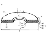
- FIG. 1 is an explanatory diagram of a glass substrate for a magnetic recording medium according to an embodiment of the present invention.
- FIG. 2 is a partially enlarged view of a cross-sectional view of the glass substrate for a magnetic recording medium shown in FIG.
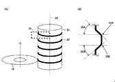
- FIG. 3 is an explanatory diagram of a grindstone used in the chamfering process.
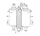
- FIG. 4 is an explanatory diagram of a configuration example of an end surface polishing apparatus used in the end surface polishing step.
- Glass substrate for magnetic recording media One structural example of the glass substrate for magnetic recording media of this embodiment is demonstrated.
- the glass substrate for a magnetic recording medium of this embodiment is a glass substrate for a magnetic recording medium having a pair of main surfaces, an outer peripheral end surface, and an inner peripheral end surface, and the outer peripheral end surface is an outer peripheral side surface portion and an outer peripheral side surface portion. And an outer peripheral chamfer disposed between the main surface and the main surface.
- the axis parallel to the main surface is the X axis
- the X coordinate of the outermost peripheral position of the outer peripheral end surface is 0, the outer periphery
- the X coordinate on the central axis side of the glass substrate for magnetic recording media is more positive than the outermost peripheral position of the end face.
- an angle formed by a straight line connecting a point having an X coordinate of 5 ⁇ m and a point having an X coordinate of 10 ⁇ m on the outer peripheral end face and the X axis can be 81 ° or more and 85 ° or less.
- an angle formed by a straight line connecting a point having an X coordinate of 10 ⁇ m and a point having an X coordinate of 20 ⁇ m on the outer peripheral end surface and the X axis can be 69 ° or more and 83 ° or less.
- an angle formed by a straight line connecting a point having an X coordinate of 20 ⁇ m and a point having an X coordinate of 30 ⁇ m on the outer peripheral end surface and the X axis may be 52 ° or more and 72 ° or less.
- glass substrate for a magnetic recording medium of the present embodiment (hereinafter also simply referred to as “glass substrate”) will be described with reference to FIG.
- FIG. 1 schematically shows a perspective sectional view of the glass substrate of the present embodiment.
- FIG. 1 is a perspective cross-sectional view including a cross section in a plane passing through the central axis O of the glass substrate 10 and perpendicular to the main surfaces 121 and 122. That is, in FIG. 1, the half of the glass substrate of this embodiment and sectional drawing are shown collectively.
- the glass substrate 10 has a circular shape on the outer periphery, and a circular shape in which a circular opening (center opening) 11 is provided in the center so as to be concentric with the outer periphery, that is, a donut. It has a shape.
- the upper and lower surfaces are main surfaces 121 and 122.
- the glass substrate 10 has the outer peripheral end surface 13 located in an outer periphery, and the inner peripheral end surface 14 located in an inner periphery.
- the outer peripheral end surface 13 and the inner peripheral end surface 14 can have chamfered portions on the main surfaces 121 and 122 side, respectively. That is, the outer peripheral end surface 13 and the inner peripheral end surface 14 can each have a pair of chamfered portions. Specifically, the outer peripheral end surface 13 can have outer peripheral chamfered portions 131 and 133, and the inner peripheral end surface 14 can have inner peripheral chamfered portions 141 and 143, respectively.
- a side surface portion can be formed between the chamfered portions, the outer peripheral end surface 13 can have the outer peripheral side surface portion 132, and the inner peripheral end surface 14 can have the inner peripheral side surface portion 142.
- the outer peripheral side surface portion 132 and the inner peripheral side surface portion 142 can be formed so as to be substantially perpendicular to the main surfaces 121 and 122, respectively.
- the outer peripheral end surface 13 can include the outer peripheral side surface portion 132 and the outer peripheral chamfered portions 131 and 133
- the inner peripheral end surface 14 can include the inner peripheral side surface portion 142 and the inner peripheral chamfered portions 141 and 143.
- the size of the glass substrate 10 of this embodiment is not specifically limited, It can select arbitrarily according to the specification of a glass substrate.
- the diameter D of the glass substrate of this embodiment can be made into the size according to the specification requested
- the diameter of the glass substrate of the present embodiment is preferably 65 mm or more, for which demand has been increasing in recent years.
- the inventors of the present invention diligently studied a glass substrate that can suppress the occurrence of cracking even when a sudden temperature change is applied during heat treatment or the like.
- the cracks that are generated when a sudden temperature change is applied during heat treatment or the like are caused mainly by the thermal expansion or contraction of the outer peripheral end surface, starting from minute cracks contained in the outer peripheral end surface. I found out.
- the inventors of the present invention further studied, and the shape of the outer peripheral end surface, specifically, the shape of the outer peripheral end surface in a cross section perpendicular to the main surface and passing through the central axis of the glass substrate, that is, the contour shape of the outer peripheral end surface It has been found that cracking can be suppressed in the case of a predetermined shape.
- FIG. 2 is an enlarged view of a region 15 indicated by a dotted line in FIG.
- FIG. 2 is an enlarged view of the periphery of the outer peripheral end face in a cross section perpendicular to the pair of main surfaces 121 and 122 and passing through the central axis O of the glass substrate 10 as shown in FIG.
- the axis parallel to the main surface 121 is taken as the X axis
- the X coordinate of the outermost peripheral position of the outer peripheral end surface 13 is 0, and the outermost peripheral position of the outer peripheral end surface 13 is more than that for the magnetic recording medium.
- the X coordinate on the central axis side of the glass substrate is positive.
- the outer peripheral end surface 13 includes an outer peripheral side surface portion 132 and outer peripheral chamfered portions 131 and 133, and the outer peripheral side surface portion 132 is substantially perpendicular to the pair of main surfaces 121 and 122. It has become. For this reason, when the outer peripheral side surface portion 132 includes a straight line portion perpendicular to the main surfaces 121 and 122, the straight line portion can be set to the outermost peripheral position where the X coordinate is zero.
- the X coordinate is 0 at the intersection of the tangent line of the outer peripheral side surface 132 perpendicular to the main surfaces 121 and 122 and the X axis. It can be set as the outermost peripheral position.
- a point P 5 in the X-coordinate X 5 is 5 [mu] m
- the straight line X-coordinate X 10 is connecting the point P 10 of 10 [mu] m
- the angle ⁇ 5-10 formed by and can be 81 ° or more and 85 ° or less.
- a point P 10 of the X-coordinate X 10 is 10 [mu] m
- the straight line X-coordinate X 20 is connecting the point P 20 of 20 [mu] m
- the angle theta 10-20 where the X-axis to form 69 The angle can be not less than 83 ° and not more than 83 °. Note that parallel to the X-axis in the figure 2, it shows a straight line X B through P 20, and the straight line X B, the angle formed by the meeting of a straight line P 10 P 20 becomes the theta 10-20.
- a point P 20 of the X-coordinate X 20 is 20 [mu] m
- the straight line X-coordinate X 30 is connecting the point P 30 of 30 [mu] m
- the angle theta 20-30 where the X-axis to form 52 It can be set in the range from ° to 72 °.
- parallel to the X-axis in the figure 2 shows a straight line X C through the P 30, and the straight line X C, the angle the straight line P 20 P 30 makes the above theta 20-30.
- the glass substrate of the present embodiment has the above shape from the outer peripheral chamfered portion to the outer peripheral chamfered portion, so that the inclination gradually changes from the outer peripheral side surface portion toward the outer peripheral chamfered portion, and has such a shape. Thus, it is possible to suppress the occurrence of cracks when a sudden temperature change is applied.
- the heat treatment when heat treatment is performed to form a magnetic layer or the like on a glass substrate, the heat treatment is performed in a state where the glass substrate is supported by a support member, and the magnetic layer or the like is formed depending on the process.
- the support member is pressed to each of a plurality of locations on the outer peripheral end surface so that the main surface is not covered with the support member, It is supported by sandwiching the glass substrate with a support member.
- the surface facing the outer peripheral end surface of the support member usually has a shape corresponding mainly to the outer peripheral side surface portion of the outer peripheral end surface.
- the outer peripheral end surface of the glass substrate of this embodiment has a gentle change in the inclination of the surface between the outer peripheral side surface portion and the outer peripheral chamfered portion as described above, the support member and the outer peripheral end surface A contact area becomes large and the force applied to a glass substrate from a supporting member can be disperse
- the glass substrate of this embodiment it can suppress that force is locally applied to a glass substrate by a supporting member, and also from such a viewpoint, occurrence of cracking when a sudden temperature change is applied. Can be suppressed.
- ⁇ 5-10 and ⁇ 10-20 are large, so that the contact area between the glass substrate and the support member can be widened and added to the glass substrate. Since the force can be dispersed, it is possible to suppress chipping, that is, chipping, between the outer peripheral side surface portion and the outer peripheral chamfered portion of the outer peripheral end surface of the glass substrate when the magnetic layer or the like is formed.
- a voltage may be applied to the base material including the glass substrate by the support member.
- the support member there was a case where the contact area between the glass substrate and the glass substrate was not sufficient, and the glass substrate was not stable and an arc was generated. When the arc is generated, dust is generated, and in some cases, the missing count increases in the inspection of the manufactured magnetic recording medium.
- the outer peripheral end surface has the structure described above, the contact area between the support member and the outer peripheral end surface is widened, and the glass substrate can be supported stably. For this reason, since generation
- the glass substrate of the present embodiment is perpendicular to the pair of main surfaces and passes through the central axis of the glass substrate, with the axis parallel to the main surface 121 as the X axis and the outermost peripheral position X of the outer peripheral end surface 13. More preferably, the following configuration is satisfied when the coordinate is 0 and the X coordinate on the central axis side of the glass substrate is positive rather than the outermost peripheral position of the outer peripheral end face 13.
- a point P 5 in the X-coordinate X 5 is 5 [mu] m
- the straight line X-coordinate X 10 is connecting the point P 10 of 10 [mu] m
- a point P 10 of the X-coordinate X 10 is 10 [mu] m
- the straight line X-coordinate X 20 is connecting the point P 20 of 20 [mu] m
- the angle theta 10-20 where the X-axis to form the 75 It is more preferable that the angle is not less than ° and not more than 82 °.
- a point P 20 of the X-coordinate X 20 is 20 [mu] m
- the straight line X-coordinate X 30 is connecting the point P 30 of 30 [mu] m
- a point P 30 of the X-coordinate X 30 is 30 [mu] m
- the straight line X-coordinate X 40 is connecting the point P 40 of 40 [mu] m
- parallel to the X-axis in the figure 2 it shows a straight line X D through P 40, and the straight line X D, the angle formed by the meeting of a straight line P 30 P 40 becomes the theta 30-40.
- FIG. 2 shows an enlarged view of the periphery of the outer peripheral chamfered portion 131 and the outer peripheral side surface portion 132 in the outer peripheral end surface 13 shown in FIG.
- the outer peripheral end surface 13 of the glass substrate of this embodiment has a pair of outer peripheral chamfered portions 131 and 133 and an outer peripheral side surface portion 132.
- the part of one outer peripheral chamfer 131 and the outer peripheral side part 132 but also the other outer peripheral chamfer 133 and the outer peripheral side part 132 have the same configuration as described above. Can do.
- the glass material is not particularly limited, and various glass materials can be used. However, as for the glass material used for the glass substrate, it is more preferable to use a glass substrate that does not easily crack even when a sudden temperature change is applied.
- the glass substrate of the present embodiment is more preferably made of a glass material having an average coefficient of thermal expansion of less than 50 ⁇ 10 ⁇ 7 / ° C. in a temperature range of 50 ° C. or higher and 350 ° C. or lower.
- the glass substrate can be prevented from expanding and contracting due to the temperature change. This is because even when added, cracking can be suppressed in combination with the shape of the outer peripheral end face.
- the lower limit value of the average thermal expansion coefficient in the temperature range of 50 ° C. or higher and 350 ° C. or lower is not particularly limited, and the glass substrate of the present embodiment has, for example, thermal expansion in the temperature range of 50 ° C. or higher and 350 ° C. or lower.
- a glass material having a coefficient larger than 0 can be used.
- SiO 2 is 62% to 74%
- Al 2 O 3 is 7% to 18%
- B 2 O 3 is 2% to 15% in terms of mole percentage.
- MgO is contained in an amount of 0 to 10%
- CaO, SrO and BaO are contained in a total of 1% to 21%
- the total content of MgO, CaO, SrO and BaO is 8% to 21%. % Or less, and those having a total content of the above seven components of 95% or more can be suitably used.
- SiO 2 is 62% or more and 74% or less
- Al 2 O 3 is 7% or more and 18% or less
- B 2 O 3 is 0 or more and less than 2% in terms of mole percentage.
- MgO, CaO, SrO and BaO with a total content of 5% or more and 18% or less and a total content of the seven components of 95% or more can be suitably used.
- the molar in percentage display As the glass material of the glass substrate of this embodiment, the molar in percentage display, a SiO 2 60% to 75% or less, Al 2 O 3 17% 7% more or less, B 2 O 3 0 2% or more
- the total content of MgO, CaO, SrO and BaO is more than 18% and 26% or less, and the total content of the seven components is 95% or more.
- the glass substrate of this embodiment can suppress the occurrence of cracking even when a sudden temperature change is applied as described above. For this reason, it can be particularly suitably used as a glass substrate for an energy-assisted magnetic recording medium that may be subjected to a rapid temperature change in the manufacturing process.
- an energy assisted magnetic recording medium in order to promote the ordering of an FePt-based magnetic layer alloy (magnetic material) contained in the magnetic layer, it is 600 ° C. to 700 ° C. during film formation of the magnetic layer. Generally, heat treatment is performed at a high temperature.
- the glass substrate of this embodiment since the shape of the outer peripheral end surface is a predetermined shape, it is possible to suppress the occurrence of cracking even when a sudden temperature change is applied.
- the glass substrate of the present embodiment can be particularly suitably used as a glass substrate for a magnetic recording medium for an energy-assisted magnetic recording medium.
- the use of the glass substrate of the present embodiment is not limited to a glass substrate for energy-assisted magnetic recording media, and can be suitably used as a glass substrate for various magnetic recording media.
- glass substrate manufacturing method a configuration example of the glass substrate for a magnetic recording medium according to the present embodiment described so far (hereinafter simply referred to as “glass substrate manufacturing method”) will be briefly described.
- the glass substrate for magnetic recording media as stated above can be manufactured.
- some description is abbreviate
- the glass substrate manufacturing method of the present embodiment can include, for example, the following steps 1 to 5.
- Step 1 A shape imparting step of processing from a glass base plate into a disc-shaped glass substrate having a circular hole in the center.
- Step 2 A chamfering step for chamfering the inner surface and the outer edge of the glass substrate.
- Step 3 An end surface polishing step for polishing the end surfaces (the inner peripheral end surface and the outer peripheral end surface) of the glass substrate.
- Step 4) A main surface polishing step for polishing the main surface of the glass substrate.
- Step 5 A cleaning / drying step of cleaning and drying the glass substrate.
- the shape imparting step of (Step 1) is a glass-shaped glass plate formed by a float method, a fusion method, a press molding method, a down draw method or a redraw method.
- the substrate is processed.
- the glass base plate used may be amorphous glass, crystallized glass, or tempered glass having a tempered layer on the surface layer of the glass substrate.
- the inner peripheral end surface and the outer peripheral end surface can be chamfered.
- the inner peripheral chamfered portions 141 and 143 can be formed on the inner peripheral end surface 14, and the outer peripheral chamfered portions 131 and 133 can be formed on the outer peripheral end surface 13.
- the corners between the outer peripheral side surface portion 132 and the outer peripheral chamfered portions 131 and 133 are radiused. Is preferably a circular arc curve of a circle of 0.3 mm to 0.4 mm.
- the chamfering of the outer peripheral end surface of the glass substrate is usually performed using a grindstone 31 having a substantially cylindrical shape as shown in FIG. 3A and having a plurality of grooves 32 formed on the peripheral surface.
- the chamfering can be performed by rotating the central axis 33 as a rotation axis.
- the groove 32 has a cross-sectional shape corresponding to the shape of the outer peripheral end face of the glass substrate to be formed.
- the corner portion between the outer peripheral side surface portion 132 and the outer peripheral chamfered portions 131 and 133 is a circular arc curve having a radius of 0.3 mm or more and 0.4 mm or less, a groove having a cross-sectional shape corresponding thereto. 32 is required.
- FIG. 3B shows a cross-sectional view of the groove 32 on the surface 34 passing through the central axis 33 and the groove 32 of the grindstone 31.
- the groove 32 includes the outer peripheral side surface portion 132, the outer peripheral chamfered portion 131, The portions 35 ⁇ / b> A and 35 ⁇ / b> B that grind the corners between the first and second portions 133 have a corresponding curved surface shape.
- channel 32 can form the outer peripheral chamfering part of a predetermined chamfering angle by making side wall part angle 36A, 36B into an angle corresponding to the chamfering angle of an outer peripheral chamfering part.
- chamfering can be similarly performed also about an inner peripheral end surface using the grindstone of the substantially cylindrical shape which has the groove
- the end surface (side surface portion and chamfered portion) of the glass substrate can be subjected to end surface polishing.
- FIG. 4 illustrates a configuration example of an end surface polishing apparatus used in the end surface polishing step.
- glass substrate laminates 41 and 42 obtained by laminating glass substrates that are objects to be polished can be prepared.
- the glass substrate laminates 41 and 42 can be laminated by arranging a spacer between the opposing main surfaces of the glass substrate.
- the brushes 43 and 44 are preferably arranged so as to be sufficiently pressed against the glass substrate laminates 41 and 42.
- the brushes 43 and 44 can move along the height directions A and B in the drawing, respectively, and can polish the end faces of all the glass substrates included in the glass substrate laminate.
- the wire diameter of the brush hair of the brush 43 and the wire diameter of the brush hair of the brush 44 differ. This is because by using a combination of brushes having different bristle diameters, the outer peripheral chamfered portion surface on the main surface side can be polished while rounding the corner portion between the outer peripheral chamfered portion and the outer peripheral side surface portion. For example, it is preferable to use a brush having a bristle wire diameter of 0.3 mm in combination with a brush having a bristle wire diameter of 0.2 mm.
- the outer peripheral end surface of the glass substrate is preferably polished with a polishing amount of 40 ⁇ m or more and 70 ⁇ m or less.
- the bristle is used in combination with, for example, the above-described wire diameter for the outer peripheral end surface of the glass substrate in which the corner portion between the outer peripheral side surface portion and the outer peripheral chamfered portion has a predetermined arc curve.
- a double-side polishing apparatus supplies polishing liquid to the main surface of the glass substrate having a donut shape, and the upper and lower main surfaces of the glass substrate having a donut shape can be simultaneously polished.
- the main surface polishing step may be only primary polishing (primary polishing), primary polishing and secondary polishing may be performed, or tertiary polishing may be performed after secondary polishing.
- wrapping of the main surface may be performed before performing the primary polishing of the main surface.
- a primary lap may be used, and a plurality of lap processes such as a secondary lap may be performed.
- glass substrate cleaning inter-process cleaning
- glass substrate surface etching inter-process etching
- main surface lapping is a broad surface main surface polishing.
- the cleaning / drying step of (Step 5) is a step of cleaning and drying the polished glass substrate.
- a specific cleaning method is not particularly limited. For example, cleaning can be performed by scrub cleaning using a detergent, ultrasonic cleaning in a state immersed in a detergent solution, ultrasonic cleaning in a state immersed in pure water, or the like. Moreover, it does not specifically limit about the drying method, For example, it can dry with isopropyl alcohol vapor
- glass substrate cleaning inter-process cleaning
- glass substrate surface etching inter-process etching
- the reinforcing step for example, chemical strengthening step
- polishing processes are performed before or after the polishing step mentioned in steps 3 and 4, Or you may implement between grinding
- a main surface polishing step may be performed before the shape imparting step.
- each step is not limited to one time, and can be performed any number of times according to the required glass substrate specifications.
- the main surface polishing step may be performed after the shape imparting step, and then the chamfering step and the end surface polishing step may be performed, and then the main surface polishing step may be performed again.
- the shape of the outer peripheral end face is a predetermined shape, it is possible to suppress the occurrence of cracking when a sudden temperature change is applied. .
- the contact area between the glass substrate and the support member when performing heat treatment or the like of the glass substrate can be increased, and the force applied to the glass substrate can be dispersed.
- the magnetic layer and the like are formed, it is possible to suppress chipping, that is, chipping, on the outer peripheral end surface of the glass substrate when the glass substrate is supported by the support member.
- the outer peripheral end surface has the structure described above, the contact area between the support member and the outer peripheral end surface is widened, and the glass substrate can be stably supported. For this reason, when forming a magnetic layer etc., even when a voltage is applied with respect to the base material containing a glass substrate by a support member, generation
- Magnetic recording medium Next, a configuration example of the magnetic recording medium of this embodiment will be described.
- the magnetic recording medium of the present embodiment can include the above-described glass substrate for a magnetic recording medium.
- the configuration of the magnetic recording medium of the present embodiment will be described below.
- the glass substrate for magnetic recording medium described above can be applied to magnetic recording media of various recording methods, the magnetic recording of the present embodiment
- the configuration of the medium is not particularly limited.
- the magnetic recording medium of the present embodiment can be manufactured by forming a perpendicular magnetic layer or the like serving as a perpendicular magnetization film on the main surface of the glass substrate described above.
- Examples of the magnetic material forming the perpendicular magnetic layer include a CoCrPt alloy and an FePt alloy.
- the magnetic recording medium of this embodiment can have a configuration in which, for example, a perpendicular magnetic layer, a protective layer, and a lubricating film are formed on the main surface of the glass substrate described above.
- a material corresponding to the perpendicular magnetic recording system can be used for the perpendicular magnetic layer.
- an energy assisted magnetic recording method for example, a heat assisted magnetic recording method, a microwave assisted magnetic recording method, etc.
- the perpendicular magnetic layer has an energy assisted magnetic recording method.
- a material corresponding to the recording method can be used.
- a soft magnetic underlayer made of a soft magnetic material that plays a role of circulating a recording magnetic field from a magnetic head.
- a soft magnetic material containing Co, Fe, Ni or the like is used for the soft magnetic underlayer.
- FeCo alloy, FeNi alloy, FeAl alloy, FeCr alloy, FeTa alloy, FeMg alloy, FeZr alloy, FeC alloy, FeN alloy, FeSi alloy, FeP alloy, FeNb Alloys, FeHf alloys, FeB alloys and the like are used.
- an adhesion layer may be provided.
- the material for forming the adhesion layer include Cr, Cr alloy, Ti, Ti alloy and the like, and a thickness of about 2 nm to 40 nm is preferable.
- the adhesion layer can be formed by film formation by sputtering, for example.
- the orientation control layer can be made of a material containing Ru, Ru alloy, Pt, Au and Ag, and a material such as CoCr alloy, Ti or Ti alloy, and the film thickness is preferably about 2 nm to 20 nm.
- This orientation control layer has a function of facilitating the epitaxial growth of the perpendicular magnetic layer and a function of breaking the magnetic exchange coupling between the soft magnetic underlayer and the perpendicular magnetic layer.
- a seed layer for controlling the crystal grain size of the orientation control layer may be provided between the soft magnetic underlayer and the orientation control layer.
- a NiW alloy can be used for the seed layer.
- the perpendicular magnetic layer is a magnetic film having an easy axis of magnetization that is perpendicular to the main surface of the glass substrate, and is formed of a material containing Co, Cr, Pt, or the like.
- the perpendicular magnetic layer preferably has a well-isolated fine particle structure, that is, a granular structure, in order to reduce intergranular exchange coupling that causes high intrinsic medium noise.
- a well-isolated fine particle structure that is, a granular structure, in order to reduce intergranular exchange coupling that causes high intrinsic medium noise.
- an oxide SiO 2 , SiO, Cr 2 O 3 , CoO, Ta 2 O 5 , TiO 2, etc.
- Cr, B, Ta, Zr, or the like may be added to a CoCrPt alloy or the like. preferable.
- the perpendicular magnetic layer may have a structure in which magnetic layers and nonmagnetic layers are alternately stacked.
- the nonmagnetic layer is made of Ru or a Ru alloy and has a thickness of 0.6 nm to 1.2 nm, whereby the magnetic layer can be AFC-coupled (antiferromagnetic exchange coupled).
- a protective layer is formed on the perpendicular magnetic layer.
- the protective layer is formed of a material containing C, ZrO 2 , SiO 2 or the like, and can be formed by film formation by sputtering, CVD (chemical vapor deposition), or the like.
- a lubricating film can be disposed on the surface of the protective layer in order to reduce friction between the magnetic head and the magnetic recording medium.
- the lubricating film for example, perfluoropolyether, fluorinated alcohol, fluorinated carboxylic acid, or the like can be used. These lubricating films can be formed by dipping, spraying, or the like.
- the magnetic recording medium of the present embodiment described above includes the above-described glass substrate for magnetic recording medium. That is, it includes a glass substrate for a magnetic recording medium that suppresses the occurrence of cracking when a sudden temperature change is applied. For this reason, when forming a magnetic layer, etc., it can suppress that a glass substrate cracks, and can manufacture the magnetic recording medium of this embodiment with high productivity.
- Shape of outer peripheral end surface The shape of the outer peripheral end surface of the glass substrate produced in each of the following experimental examples was measured by a contour shape measuring instrument (model: CONTOURRECORD 1600DH manufactured by Tokyo Seimitsu Co., Ltd.). The stylus tip R at the time of measurement was 30 ⁇ m, and the scanning speed was 0.3 mm / sec.
- the axis parallel to the main surface was taken as the X axis.
- the X coordinate of the outermost peripheral position in the outline shape of the outer peripheral end surface of each glass substrate was set to 0, and the X coordinate on the central axis side of the glass substrate from the outermost peripheral position of the outer peripheral end surface was made positive.
- the angle theta 5-10 to X coordinate X 5 is the point P 5 of 5 [mu] m
- the straight line X-coordinate X 10 is connecting the point P 10 of 10 [mu] m
- the angle theta 10-20 of X-coordinate X 10 is a point P 10 of 10 [mu] m
- the straight line X-coordinate X 20 is connecting the point P 20 of 20 [mu] m
- the angle theta 20-30 of X-coordinate X 20 is a point P 20 of 20 [mu] m
- the straight line X-coordinate X 30 is connecting the point P 30 of 30 [mu] m
- the angle theta 30-40 of X-coordinate X 30 is a point P 30 of 30 [mu] m
- the straight line X-coordinate X 40 is connecting the point P 40 of 40 [mu] m
- the glass substrate produced in each experimental example is heated to 230 ° C. in an electric furnace and then taken out from the electric furnace without cooling. Then, the glass substrate is moved in a direction parallel to the main surface of the glass substrate to the water in the water tank in which the water temperature is 20 ° C. and the depth is 10 mm in advance, that is, the water surface and the main surface of the glass substrate Insert while keeping the vertical position.
- the ratio of the glass substrates determined to have cracked in the 100 glass substrates subjected to the test that is, a length of 5 mm or more from the outer peripheral portion.
- the ratio of the glass substrate in which the crack or the crack has occurred is defined as the crack occurrence rate.
- the glass substrate was heated to 230 ° C. and then poured into water having a water temperature of 20 ° C. within 3 seconds. For this reason, a rapid temperature change of about 70 ° C./second is applied to the glass substrate.
- the most rapid temperature change in the process of manufacturing the energy-assisted magnetic recording medium is maintained, for example, from about 600 ° C. required for ordering the Fe—Pt alloy film to about 200 ° C. for forming the protective layer. This occurs when transferred to a CVD chamber.
- the temperature change is performed over a period of several tens of seconds to several tens of seconds. For this reason, even if the time required for the temperature change is estimated as 15 seconds, the temperature change is about 27 ° C./second.
- the temperature is larger than the temperature gradient when manufacturing the magnetic recording medium.
- the evaluation is performed with a gradient.
- an evaluation of the occurrence rate of chipping is performed on the outer peripheral edge of the glass substrate after the magnetic layer is formed. Visual confirmation is made and it is determined that chipping has occurred for the glass substrate including chipping.
- 10,000 glass substrates were tested, and the ratio of the glass substrates in which chipping occurred in the 10,000 glass substrates was defined as the chipping occurrence rate.
- the evaluation was performed separately between the outer peripheral chamfered portion and the outer peripheral chamfered portion and between the main surface and the outer peripheral chamfered portion.
- Table 3 the occurrence rate of chipping between the outer peripheral chamfered portion and the outer peripheral side surface portion is described as between the outer peripheral chamfered portion and the outer peripheral side surface portion.
- Table 3 the occurrence rate of chipping between the main surface and the outer peripheral chamfered portion is described as between the main surface and the outer peripheral chamfered portion.
- the missing bit is recorded under the conditions of a linear recording density of 1600 kBPI and a track density of 500 kTPI (surface recording density of 800 Gbit / inch 2 ), and is evaluated by measuring the signal intensity when reproduced.
- the missing bit is used as the missing bit.
- the collectable missing bits Correctable Missing Bit
- those that cannot be modified less than 80% of the first threshold
- uncorrectable missing bits Uncorrectable Missing Bit
- 500 magnetic recording media prepared in each experimental example are measured and calculated as the number per one surface.
- the evaluation of the magnetic disk is indicated by ranks A, B, C and D based on the collectable missing bit and the uncorrectable missing bit measured in this way. Specifically, as shown in Table 1, when the collectable missing bit is 0.3 or less (pieces / face), the uncorrectable missing bit is 0.1 or less (pieces / face) , Rank A.
- the uncorrectable missing bit is greater than 0.1 and less than or equal to 0.2 (pieces / face).
- the uncorrectable missing bit is greater than 0.2 and less than or equal to 0.3 (pieces / face).
- the rank is D.
- Experimental examples 1 to 5 are examples, and experimental examples 6 to 9 are comparative examples.
- Example 1 Each step is performed in the following order to manufacture a glass substrate for a magnetic recording medium and a magnetic recording medium.
- Glass substrate for magnetic recording medium shape imparting step
- An aluminosilicate glass base plate having a glass composition A shown in Table 2 mainly composed of SiO 2 and formed by a float process is prepared. Then, the glass base plate is processed into a glass substrate having a donut shape having a circular hole in the center so that a glass substrate for a magnetic recording medium having an outer diameter of 65 mm, an inner diameter of 20 mm, and a plate thickness of 0.8 mm can be obtained.
- the inner diameter means the diameter of the central opening.
- an inner peripheral end face grinding grind for grinding the inner peripheral end face and an outer peripheral end face grindstone for grinding the outer peripheral end face are used.
- the inner peripheral end face grinding wheel and the outer peripheral end face grinding grindstone each have a substantially cylindrical shape, and use a grindstone having grooves 32 along the peripheral face. .
- the outer peripheral end surface polishing grindstone has a cross-sectional shape of the groove 32 on the surface 34 passing through the central axis 33 and the groove 32 of the grindstone 31, and the outer peripheral side surface portion 132,
- the portions 35A and 35B for grinding the corners between the outer peripheral chamfered portions 131 and 133 have an arc shape with a radius of 0.40 mm. That is, R is a curve of 0.40 mm.
- the grinding wheel bottom R is shown.
- the side wall angle 36A, 36B is set to 43 °.
- the inner peripheral end surface polishing grindstone is a circular arc having a radius of 0.15 mm with respect to the portions 35A and 35B where the cross-sectional shape of the groove 32 grinds the corners between the inner peripheral side surface portion 142 and the inner peripheral chamfered portions 141 and 143. It has a shape. That is, a curve with R of 0.15 mm was used. Further, the side wall angle 36A, 36B is set to 43 °.
- the chamfering process is performed in two steps for both the inner peripheral side surface portion and the outer peripheral side surface portion, and the first stage grindstone is a particle size # 325, and the second stage grindstone is a diamond electrodeposition grindstone of particle size # 800. Yes.
- the upper and lower main surfaces of the glass substrate are ground by a 16B double-side polishing apparatus using a cast iron surface plate as a polishing tool and a grinding liquid containing alumina abrasive grains. After completion of the primary lapping process, the glass substrate is washed to remove grinding fluid and other dirt.
- End face polishing process outer peripheral end face polishing process
- the outer peripheral side surface portion and the outer peripheral chamfered portion are polished using a polishing brush and an abrasive containing a cerium oxide abrasive having an average particle diameter (hereinafter, abbreviated as an average particle size) of about 1.5 ⁇ m.
- the wrinkles at the outer peripheral chamfered portion are removed, and the outer peripheral end surface is polished so as to be a mirror surface.
- the outer peripheral end face is polished using the end face polishing apparatus shown in FIG.
- the glass substrate laminates 41 and 42 are formed by laminating 100 glass substrates that have been subjected to the main surface polishing step (primary lapping step) through a resin spacer having a thickness of 0.4 mm.
- a roll polishing brush made of nylon having a diameter of 0.3 mm is used
- a roll polishing brush made of nylon having a diameter of 0.2 mm is used.
- the brushes 43 and 44 are pressed against the outer periphery of the glass substrate laminates 41 and 42 so that the brush pressing amount of each brush is 4 mm, and the glass substrate laminates 41 and 42 and the brushes 43 and 44 are rotated. Polishing is performed so that the polishing amount of the outer peripheral end face becomes 60 ⁇ m.
- the average particle size means the particle size at an integrated value of 50% in the particle size distribution obtained by the laser diffraction / scattering method. In other parts of the present specification, the average particle size has the same meaning.
- End polishing process Inner peripheral edge polishing process
- the glass substrate After polishing the outer peripheral end face and inner peripheral end face, the glass substrate is washed to remove the abrasive and other dirt.
- the upper and lower main surfaces of the glass substrate are ground by a 16B double-side polishing apparatus using a fixed abrasive tool containing diamond particles having an average particle diameter of 4 ⁇ m as a polishing tool and a grinding liquid containing a surfactant.
- the glass substrate is cleaned to remove grinding fluid and other dirt.
- main surface polishing process primary polishing process
- a soft urethane polishing pad suede type polishing pad
- a grinding liquid containing cerium oxide having an average particle size of about 1.0 ⁇ m as a main component are used as a polishing tool.
- the upper and lower main surfaces of the glass substrate are polished by a 16B double-side polishing apparatus.
- the main polishing pressure is 12 kPa
- the lower surface plate rotation speed is 30 rpm
- the upper surface plate rotation speed is 10 rpm in the opposite direction to the lower surface plate
- the polishing carrier revolution number is 10 rpm
- the rotation speed is 3 rpm
- the upper and lower main planes are total in the plate thickness direction. Polish 30 ⁇ m.
- the glass substrate is washed to remove grinding fluid and other dirt.
- main surface polishing process secondary polishing process
- a polishing pad containing a soft urethane polishing pad and a colloidal silica abrasive having an average particle size of 20 nm is used as a polishing tool, and a 16B double-side polishing apparatus is used to make glass Polish the upper and lower main surfaces of the substrate.
- the main polishing pressure is 10 kPa
- the lower surface plate rotation speed is 10 rpm
- the upper surface plate rotation speed is 5 rpm in the opposite direction of the lower surface plate
- the polishing carrier revolution number is 4.9 rpm
- the rotation speed is 1.7 rpm.
- a total of 1 ⁇ m is polished in the thickness direction.
- the glass substrate After completion of the main surface polishing step (secondary polishing step), the glass substrate is washed to remove grinding fluid and other contaminants.
- the glass substrate that has been subjected to the main surface polishing step is sequentially subjected to scrub cleaning with an alkaline detergent, ultrasonic cleaning in a state immersed in an alkaline detergent solution, and ultrasonic cleaning in a state immersed in pure water. (Precise cleaning), followed by drying with isopropyl alcohol vapor.
- a supporting member is pressed against a plurality of locations on the outer peripheral end face of the glass substrate, and the glass substrate is sandwiched between the supporting members to support the glass substrate.
- a soft magnetic underlayer is formed with a thickness of 30 nm using a Co—Fe—Zr—Ta alloy as a target.
- a seed layer is formed with a thickness of 10 nm using a NiW alloy as a target.
- an orientation control layer is formed with a thickness of 10 nm using Ru as a target.
- a granular structure layer of CoCrPt—SiO 2 is formed as a perpendicular magnetic layer with a thickness of 10 nm, a Ru film is formed as a nonmagnetic intermediate layer with a thickness of 0.6 nm, and a magnetic layer A granular structure layer of CoCrPt—SiO 2 is formed with a thickness of 6 nm.
- the glass substrate on which each of the above layers is laminated is transferred from an in-line type sputtering apparatus, and a carbon film is formed with a thickness of 3 nm as a protective layer by a CVD method. Thereafter, a perfluoropolyether lubricating film having a thickness of 2 nm is formed on the protective layer by dipping.
- Example 2 Glass substrate for magnetic recording medium Glass in the same manner as in Experimental Example 1 except that in the chamfering process, the shape of the groove of the grinding wheel for outer peripheral end face grinding is different and the polishing amount of the outer peripheral end face in the end face grinding process is different. A substrate is prepared and evaluated.
- the cross-sectional shape of the groove 32 on the surface 34 passing through the central axis 33 and the groove 32 of the grindstone 31 for outer peripheral end surface grinding is as follows.
- the portions 35A and 35B where the corners between the chamfered portions 131 and 133 are ground have an arc shape with a radius of 0.30 mm. That is, R is a curve of 0.30 mm.
- polishing is performed so that the polishing amount of the outer peripheral end face in the end face polishing step is 50 ⁇ m (Experimental Example 2) or 40 ⁇ m (Experimental Example 3).
- Magnetic recording medium A magnetic recording medium is produced in the same manner as in Experimental Example 1 except that the glass substrate for magnetic recording medium produced in each experimental example is used.
- Example 4 is an aluminosilicate glass base plate having a glass composition B shown in Table 2 and composed mainly of SiO 2 formed by a float process
- Example 5 is a glass similarly shown in Table 2.
- An aluminosilicate glass base plate having composition C is used.
- Magnetic recording medium A magnetic recording medium is produced in the same manner as in Experimental Example 1 except that the glass substrate for magnetic recording medium produced in each experimental example is used.
- the cross-sectional shape of the groove 32 on the surface 34 passing through the central axis 33 and the groove 32 of the grindstone 31 for outer peripheral end surface grinding is as follows.
- a radius of 0.20 mm (Experimental example 6)
- a radius of 0.15 mm (Experimental example 7)
- a radius of 0.10 mm (Experimental example 8)
- the arc shape has a radius of 0.60 mm (Experimental Example 9). That is, the curves R are 0.20 mm, 0.15 mm, 0.10 mm, and 0.60 mm.
- polishing is performed so that the polishing amount of the outer peripheral end face in the end face polishing step is 20 ⁇ m, 15 ⁇ m, 15 ⁇ m, and 30 ⁇ m in Examples 6, 7, 8, and 9, respectively.
- the brushes 43 and 44 are placed on the outer periphery of the glass substrate laminates 41 and 42, and the brush pressing amount of each brush is 1.5 mm in Examples 6 and 7.
- the glass substrate laminates 41 and 42 and the brushes 43 and 44 are rotated so as to have the above polishing amount by being pressed so as to be 2 mm in 8 and 3 mm in Example 9.
- both the hair diameters made of nylon in Examples 6 and 7 were 0.15 mm
- the hair diameter in Example 8 was both 0.2 mm
- the hair diameter in Example 9 was 0.
- Each roll abrasive brush of 3 mm is used.
- Magnetic recording medium A magnetic recording medium is produced in the same manner as in Experimental Example 1 except that the glass substrate for magnetic recording medium produced in each experimental example is used.
- the glass substrates of Experimental Examples 1 to 5 having the outer peripheral end surface having the shape described above have a lower rate of peripheral chipping after the magnetic layer deposition than the glass substrates of Experimental Examples 6 to 9. I can confirm that I can do it.
Landscapes
- Chemical & Material Sciences (AREA)
- Engineering & Computer Science (AREA)
- Organic Chemistry (AREA)
- Life Sciences & Earth Sciences (AREA)
- Chemical Kinetics & Catalysis (AREA)
- General Chemical & Material Sciences (AREA)
- Geochemistry & Mineralogy (AREA)
- Materials Engineering (AREA)
- Inorganic Chemistry (AREA)
- Ceramic Engineering (AREA)
- Magnetic Record Carriers (AREA)
- Glass Compositions (AREA)
- Recording Or Reproducing By Magnetic Means (AREA)
- Manufacturing Of Magnetic Record Carriers (AREA)
Abstract
本発明は、一対の主表面、外周端面、及び内周端面を有するドーナツ形状の磁気記録媒体用ガラス基板であって、一対の主表面と垂直でかつ磁気記録媒体用ガラス基板の中心軸を通る断面において、主表面と平行な軸をX軸とし、外周端面の最外周位置のX座標を0、外周端面の最外周位置よりも磁気記録媒体用ガラス基板の中心軸側のX座標を正とした場合に、外周端面のうち、X座標が5μmの点と、X座標が10μmの点とを結んだ直線と、X軸とが形成する角度が81°以上85°以下、X座標が10μmの点と、X座標が20μmの点とを結んだ直線と、X軸とが形成する角度が69°以上83°以下、X座標が20μmの点と、X座標が30μmの点とを結んだ直線と、X軸とが形成する角度が52°以上72°以下、である磁気記録媒体用ガラス基板に関する。
Description
本発明は、磁気記録媒体用ガラス基板、磁気記録媒体に関する。
磁気記録装置は、磁気記録媒体用基板上に磁性層等を成膜した磁気記録媒体を備えており、該磁性層を用いて情報を記録することができる。
磁気記録装置に用いられる磁気記録媒体用基板としては、従来、アルミニウム合金基板が使用されてきたが、高記録密度化の要求に伴い、アルミニウム合金基板に比べて硬く、平坦性や平滑性に優れるガラス基板が主流となってきている。
そして、近年では年々高まる高記録密度化のニーズに応えるため、エネルギーアシスト磁気記録方式を用いた磁気記録媒体、すなわちエネルギーアシスト磁気記録媒体が検討されている。エネルギーアシスト磁気記録媒体についても、基板として磁気記録媒体用ガラス基板を用い、磁気記録媒体用ガラス基板の主表面上に磁性層等を配置した構成を有することができる。
エネルギーアシスト磁気記録媒体では、磁性層の磁性材料として磁気異方性係数Kuの大きい(以下、「高Ku」とも記載する)規則合金が用いられている。そして、規則化の程度(規則度)を高めて高Kuを実現するため、磁性層の成膜時、成膜前、または成膜後に、磁気記録媒体用ガラス基板を含む基材を600℃~700℃程度の高温で熱処理を行う場合がある。
磁性層の成膜時、成膜前、または成膜後に高温での熱処理を行うのは、例えばエネルギーアシスト磁気記録媒体の磁性層の磁性材料として好適なFePt系合金等において、アニール温度を高くするほど保磁力を高められるためでもある。
磁気記録媒体用ガラス基板は、通常一対の主表面、外周端面、及び内周端面を有するドーナツ形状を有しており、外周端面は、主表面と略垂直な外周側面部、及び外周側面部と主表面との間に配置された外周面取り部を有している。
磁気記録媒体用ガラス基板の端面形状については、従来から各種検討がなされている。例えば特許文献1には、磁気ディスクのコロージョン対策に有効な磁気記録媒体用ガラス基板が開示されている。
具体的には、基板端面の研削加工工程を含む製造方法によって製造された磁気ディスク用ガラス基板であって、前記ガラス基板の端面は、側壁面と、該ガラス基板の両方の主表面と側壁面との間の2つの面取面とから形成され、2つの面取面のいずれにおいても面内の表面粗さRaのばらつきが±0.01μm以内であり、前記ガラス基板の端面は鏡面であって、表面粗さはRmaxで1μm以下、かつ、Raで0.1μm以下であり、前記ガラス基板の内周及び外周の面取面と側壁面の角度ばらつきが目標の角度に対して0.8度以内であることを特徴とする磁気ディスク用ガラス基板が開示されている。
ところで、磁気記録媒体用ガラス基板について、上述のような高温での熱処理時や、熱処理後の冷却時等に、急激な温度変化が加えられた際に、外周端面を起点として割れ等を生じる場合があった。このため、熱処理時に急激な温度変化が加えられた場合でも割れの発生を抑制できる磁気記録媒体用ガラス基板が求められていた。
そこで、本発明の一側面では上記従来技術が有する問題に鑑み、急激な温度変化が加えられた場合に割れが生じることを抑制した磁気記録媒体用ガラス基板を提供することを目的とする。
本発明の一側面では、一対の主表面、外周端面、及び内周端面を有するドーナツ形状の磁気記録媒体用ガラス基板であって、
前記外周端面が外周側面部、及び前記外周側面部と前記主表面との間に配置された外周面取り部を有し、
前記一対の主表面と垂直で、かつ前記磁気記録媒体用ガラス基板の中心軸を通る断面において、
前記主表面と平行な軸をX軸とし、前記外周端面の最外周位置のX座標を0、前記外周端面の最外周位置よりも、前記磁気記録媒体用ガラス基板の中心軸側のX座標を正とした場合に、
前記外周端面のうち、X座標が5μmの点と、X座標が10μmの点とを結んだ直線と、前記X軸とが形成する角度が81°以上85°以下、
前記外周端面のうち、X座標が10μmの点と、X座標が20μmの点とを結んだ直線と、前記X軸とが形成する角度が69°以上83°以下、
前記外周端面のうち、X座標が20μmの点と、X座標が30μmの点とを結んだ直線と、前記X軸とが形成する角度が52°以上72°以下、
である磁気記録媒体用ガラス基板を提供する。
前記外周端面が外周側面部、及び前記外周側面部と前記主表面との間に配置された外周面取り部を有し、
前記一対の主表面と垂直で、かつ前記磁気記録媒体用ガラス基板の中心軸を通る断面において、
前記主表面と平行な軸をX軸とし、前記外周端面の最外周位置のX座標を0、前記外周端面の最外周位置よりも、前記磁気記録媒体用ガラス基板の中心軸側のX座標を正とした場合に、
前記外周端面のうち、X座標が5μmの点と、X座標が10μmの点とを結んだ直線と、前記X軸とが形成する角度が81°以上85°以下、
前記外周端面のうち、X座標が10μmの点と、X座標が20μmの点とを結んだ直線と、前記X軸とが形成する角度が69°以上83°以下、
前記外周端面のうち、X座標が20μmの点と、X座標が30μmの点とを結んだ直線と、前記X軸とが形成する角度が52°以上72°以下、
である磁気記録媒体用ガラス基板を提供する。
本発明の磁気記録媒体用ガラス基板の一側面によれば、急激な温度変化が加えられた場合に割れが生じることを抑制した磁気記録媒体用ガラス基板を提供することができる。
以下、本発明を実施するための形態について図面を参照して説明するが、本発明は、下記の実施形態に制限されることはなく、本発明の範囲を逸脱することなく、下記の実施形態に種々の変形および置換を加えることができる。
(磁気記録媒体用ガラス基板)
本実施形態の磁気記録媒体用ガラス基板の一構成例について説明を行う。
本実施形態の磁気記録媒体用ガラス基板の一構成例について説明を行う。
本実施形態の磁気記録媒体用ガラス基板は、一対の主表面、外周端面、及び内周端面を有するドーナツ形状の磁気記録媒体用ガラス基板であって、外周端面が外周側面部、及び外周側面部と主表面との間に配置された外周面取り部を有することができる。
ここで、一対の主表面と垂直で、かつ磁気記録媒体用ガラス基板の中心軸を通る断面において、主表面と平行な軸をX軸とし、外周端面の最外周位置のX座標を0、外周端面の最外周位置よりも、磁気記録媒体用ガラス基板の中心軸側のX座標を正とする。
ここで、一対の主表面と垂直で、かつ磁気記録媒体用ガラス基板の中心軸を通る断面において、主表面と平行な軸をX軸とし、外周端面の最外周位置のX座標を0、外周端面の最外周位置よりも、磁気記録媒体用ガラス基板の中心軸側のX座標を正とする。
この場合に、外周端面のうち、X座標が5μmの点と、X座標が10μmの点とを結んだ直線と、前記X軸とが形成する角度を81°以上85°以下とすることができる。
また、外周端面のうち、X座標が10μmの点と、X座標が20μmの点とを結んだ直線と、前記X軸とが形成する角度が69°以上83°以下とすることができる。
また、外周端面のうち、X座標が20μmの点と、X座標が30μmの点とを結んだ直線と、前記X軸とが形成する角度が52°以上72°以下とすることができる。
また、外周端面のうち、X座標が10μmの点と、X座標が20μmの点とを結んだ直線と、前記X軸とが形成する角度が69°以上83°以下とすることができる。
また、外周端面のうち、X座標が20μmの点と、X座標が30μmの点とを結んだ直線と、前記X軸とが形成する角度が52°以上72°以下とすることができる。
まず、図1を用いて本実施形態の磁気記録媒体用ガラス基板(以下、単に「ガラス基板」とも記載する)の構造について説明する。
図1は本実施形態のガラス基板の斜視断面図を模式的に示している。図1はガラス基板10の中心軸Oを通り、主表面121、122と垂直な面における断面を含む斜視断面図となっている。すなわち、図1では本実施形態のガラス基板の半分と、断面図とをあわせて示している。
図1から把握されるように、ガラス基板10は外周が円形であり、中央部には外周と同心円となるように円形の開口部(中央開口部)11が設けられた円板形状、すなわちドーナツ形状を有している。
そして、上下の面が主表面121、122となっている。また、ガラス基板10は外周に位置する外周端面13と、内周に位置する内周端面14と、を有している。
外周端面13、及び内周端面14は主表面121、122側にそれぞれ面取り部を有することができる。すなわち、外周端面13、及び内周端面14は、それぞれ一対の面取り部を有することができる。具体的には外周端面13は外周面取り部131、133を、内周端面14は内周面取り部141、143をそれぞれ有することができる。
また、面取り部間には側面部を形成することができ、外周端面13は外周側面部132を、内周端面14は内周側面部142をそれぞれ有することができる。外周側面部132、及び内周側面部142はそれぞれ主表面121、122と略垂直になるように形成できる。
以上のように、外周端面13は外周側面部132と、外周面取り部131、133とを含み、内周端面14は内周側面部142と、内周面取り部141、143とを含むことができる。
なお、本実施形態のガラス基板10のサイズは特に限定されるものではなく、ガラス基板の仕様にあわせて任意に選択することができる。本実施形態のガラス基板の直径Dは例えば48mm、65mm、または95mm等のガラス基板に要求される仕様に応じたサイズとすることができる。特に、本実施形態のガラス基板の直径は、近年需要が高まっている65mm以上であることが好ましい。
本発明の発明者らは、熱処理等を行う際に急激な温度変化が加えられた場合でも割れが生じることを抑制できるガラス基板について鋭意検討を行った。そして、熱処理等を行う際に急激な温度変化が加えられた際に生じている割れは、主に外周端面の熱膨張、または熱収縮により、外周端面に含まれる微小なクラックを起点として生じていることが分かった。
そこで、本発明の発明者らはさらに検討を行い、外周端面の形状、具体的には主表面と垂直で、かつガラス基板の中心軸を通る断面における外周端面の形状、すなわち外周端面の輪郭形状が所定の形状の場合に割れを抑制できることを見出した。
ここで、図2を用いて本実施形態のガラス基板の外周端面の形状を説明する。図2は、図1において点線で示した領域15を拡大して示した図である。
図2は、図1に示したように、一対の主表面121、122と垂直で、かつガラス基板10の中心軸Oを通る断面における外周端面周辺を拡大して示した図となる。
ここで、図2に示したように、主表面121と平行な軸をX軸とし、外周端面13の最外周位置のX座標を0、外周端面13の最外周位置よりも、磁気記録媒体用ガラス基板の中心軸側のX座標を正とする。
なお、外周端面13は図1を用いて説明したように、外周側面部132と、外周面取り部131、133とを有しており、外周側面部132は一対の主表面121、122と略垂直になっている。このため、外周側面部132が主表面121、122と垂直な直線部分を含む場合には該直線部分を、X座標が0である最外周位置とすることができる。また、外周側面部132が主表面121、122と垂直な直線部分を含まない場合には、主表面121、122と垂直な外周側面部132の接線と、X軸との交点をX座標が0である最外周位置とすることができる。
この場合に、本実施形態のガラス基板10は、外周端面13のうち、X座標X5が5μmの点P5と、X座標X10が10μmの点P10とを結んだ直線と、X軸とが形成する角度θ5-10を81°以上85°以下とすることができる。
なお、図2中においてはX軸と平行で、P10を通る直線XAを示しており、直線XAと、直線P5P10とが作る角度が上記θ5-10となる。
また、外周端面13のうち、X座標X10が10μmの点P10と、X座標X20が20μmの点P20とを結んだ直線と、X軸とが形成する角度θ10-20を69°以上83°以下とすることができる。なお、図2中においてはX軸と平行で、P20を通る直線XBを示しており、直線XBと、直線P10P20とが作る角度が上記θ10-20となる。
また、外周端面13のうち、X座標X20が20μmの点P20と、X座標X30が30μmの点P30とを結んだ直線と、X軸とが形成する角度θ20-30を52°以上72°以下とすることができる。なお、図2中においてはX軸と平行で、P30を通る直線XCを示しており、直線XCと、直線P20P30とが作る角度が上記θ20-30となる。
本実施形態のガラス基板は、外周面取り部から外周側面部にかけて上記形状を有することで、外周側面部から外周面取り部に向かって傾斜が徐々に変化する形状となっており、係る形状を有することで、急激な温度変化が加わった際に割れが生じることを抑制できる。
ところで、ガラス基板に磁性層等を成膜するために熱処理を行う場合、ガラス基板を支持部材により支持した状態で、熱処理を行い、工程によっては磁性層等が成膜される。
熱処理工程や、ガラス基板上に磁性層等を成膜する工程を実施している間は、主表面が支持部材で覆われないように、外周端面上の複数箇所にそれぞれ支持部材を押し当て、支持部材でガラス基板を挟み込むことで支持している。この際、支持部材の外周端面と対向する面は通常、外周端面のうち、主に外周側面部に対応した形状を有している。
そして、本実施形態のガラス基板の外周端面は上述のように、外周側面部と、外周面取り部との間で、面の傾きの変化がなだらかな形状を有するため、支持部材と外周端面との接触面積が広くなり、支持部材からガラス基板に加えられる力を分散できる。
このため、本実施形態のガラス基板によれば、支持部材によりガラス基板に力が局所的に加えられることを抑制でき、係る観点からも、急激な温度変化が加えられた場合の割れの発生を抑制することができる。
さらに、上述のように本実施形態のガラス基板によれば、θ5-10、θ10-20が大きいので、ガラス基板と支持部材との接触面積を広くすることができ、ガラス基板に加えられる力を分散できることから、磁性層等を成膜する際に、ガラス基板の外周端面の外周側面部と外周面取り部との間においてチッピング、すなわち欠けが生じることを抑制できる。
一方、θ20-30が大きすぎると、結果として主表面と外周面取り部との間の角度を大きくすることが困難になるため、爪状の搬送ジグや収納カセットとの接触により、主表面と外周面取り部との間に於いてチッピングが発生しやすくなる。それに対し、本実施形態のガラス基板によれば、前記部分のチッピングの発生も抑制することができる。
ちなみに外周側面部と、外周面取り部との間の断面形状を、ある範囲の単一の曲率半径(例えばR=0.6~0.8mm)にすることで、θ5-10、θ10-20の値を大きく(例えばそれぞれ81°~85°、69°~83°)することは可能であるが、一方、θ20-30が大きくなり過ぎ、好適な範囲(例えば52°~72°)にすることができない。或いは、別の範囲の単一の曲率半径(例えばR=0.15~0.5mm)にすることで、θ20-30の値を好適な範囲にすることは可能であるが、逆にθ5-10またはθ10-20を充分に大きな範囲にすることができない。
また、磁性層等を成膜する際に、支持部材によりガラス基板を含む基材に対して電圧を印加する場合があるが、従来のガラス基板に磁性層を成膜する際には、支持部材とガラス基板との接触面積が十分ではなく、ガラス基板が安定せずアークが発生する場合があった。アークが発生すると、発塵し、製造した磁気記録媒体の検査において、ミッシングカウントが多くなる場合があった。
これに対して、本実施形態のガラス基板においては、外周端面が既述の構造を有するため、支持部材と外周端面との接触面積が広くなり、ガラス基板を安定して支持できる。このため、アークの発生を抑制し、ひいては発塵を抑制できるため、得られる磁気記録媒体において、ミッシングカウントを抑制することが可能になる。
また、本実施形態のガラス基板は、一対の主表面と垂直で、かつガラス基板の中心軸を通る断面において、主表面121と平行な軸をX軸とし、外周端面13の最外周位置のX座標を0、外周端面13の最外周位置よりも、ガラス基板の中心軸側のX座標を正とした場合に以下の構成を充足することがより好ましい。
外周端面13のうち、X座標X5が5μmの点P5と、X座標X10が10μmの点P10とを結んだ直線と、X軸とが形成する角度θ5-10が81°以上84°以下であることがより好ましい。
また、外周端面13のうち、X座標X10が10μmの点P10と、X座標X20が20μmの点P20とを結んだ直線と、X軸とが形成する角度θ10-20が75°以上82°以下であることがより好ましい。
外周端面13のうち、X座標X20が20μmの点P20と、X座標X30が30μmの点P30とを結んだ直線と、X軸とが形成する角度θ20-30が55°以上72°以下であることがより好ましい。
外周端面13のうち、X座標X30が30μmの点P30と、X座標X40が40μmの点P40とを結んだ直線と、X軸とが形成する角度θ30-40が51°以上68°以下であることがより好ましい。なお、図2中においてはX軸と平行で、P40を通る直線XDを示しており、直線XDと、直線P30P40とが作る角度が上記θ30-40となる。
図2では図1に示した外周端面13のうち、外周面取り部131と外周側面部132との周辺を拡大した図を示している。しかし、図1に示したように、本実施形態のガラス基板の外周端面13は、一対の外周面取り部131、133と、外周側面部132とを有している。このため、一方の外周面取り部131と外周側面部132との部分だけではなく、もう一方の外周面取り部133と外周側面部132との部分についてもここまで説明したものと同様の構成を有することができる。
本実施形態のガラス基板についてはガラス材料については特に限定されるものではなく、各種ガラス材料を用いることができる。ただし、ガラス基板に用いるガラス材料についても、急激な温度変化が加えられた場合でも、割れを生じにくいガラス基板を用いることがより好ましい。
このため、本実施形態のガラス基板は、50℃以上350℃以下の温度域における平均熱膨張係数が50×10-7/℃未満であるガラス材料からなることがより好ましい。
これは、50℃以上350℃以下の温度域における平均熱膨張係数が、50×10-7/℃未満の場合、温度変化に伴うガラス基板の膨張、収縮を抑制できるため、急激な温度変化が加えられた場合でも、外周端面の形状と相まって、割れを抑制できるからである。
なお、50℃以上350℃以下の温度域における平均熱膨張係数の下限値は特に限定されるものではなく、本実施形態のガラス基板には、例えば50℃以上350℃以下の温度域における熱膨張係数が0より大きいガラス材料を用いることができる。
本実施形態のガラス基板のガラス材料としては、モル百分率表示で、SiO2を62%以上74%以下、Al2O3を7%以上18%以下、B2O3を2%以上15%以下含有し、MgOを0以上10%以下、CaO、SrOおよびBaOのいずれか1成分以上を合計で1%以上21%以下含有し、MgO、CaO、SrOおよびBaOの含有量合計が8%以上21%以下、上記7成分の含有量合計が95%以上であるものを、好適に用いることができる。
また、本実施形態のガラス基板のガラス材料としては、モル百分率表示でSiO2を62%以上74%以下、Al2O3を7%以上18%以下、B2O3を0以上2%未満、MgO、CaO、SrOおよびBaOの含有量合計が5%以上18%以下、上記7成分の含有量合計が95%以上であるものを好適に用いることができる。
また、本実施形態のガラス基板のガラス材料としては、モル百分率表示で、SiO2を60%以上75%以下、Al2O3を7%以上17%以下、B2O3を0以上2%未満、MgO、CaO、SrOおよびBaOの含有量合計が18%超26%以下、上記7成分の含有量合計が95%以上であるものを好適に用いることができる。
本実施形態のガラス基板は、ここまで説明したように急激な温度変化を加えた場合でも割れが生じることを抑制できる。このため、製造工程で急激な温度変化を加える場合がある、エネルギーアシスト磁気記録媒体用のガラス基板として、特に好適に用いることができる。そして、エネルギーアシスト磁気記録媒体を製造する際には、磁性層に含まれるFePt系等の磁性層合金(磁性材料)の規則化促進のため、磁性層の成膜時等に600℃~700℃程度の高温で熱処理を行うのが一般的である。
既述のように、特にエネルギーアシスト磁気記録媒体を製造する際に、600℃~700℃程度の高温で熱処理を行う際に、ガラス基板に急激な温度変化が加わる場合があり、従来のガラス基板においては、割れを生じる場合があった。これに対して、本実施形態のガラス基板によれば、外周端面の形状を所定の形状としているため、急激な温度変化が加えられた場合でも割れが生じることを抑制することができる。
このため、本実施形態のガラス基板は、エネルギーアシスト磁気記録媒体用の磁気記録媒体用ガラス基板として、特に好適に用いることができる。
ただし、本実施形態のガラス基板の用途は、エネルギーアシスト磁気記録媒体用のガラス基板に限定されるものではなく、各種磁気記録媒体用のガラス基板として好適に用いることができる。
次に、ここまで説明した本実施形態の磁気記録媒体用ガラス基板の製造方法(以下、単に「ガラス基板の製造方法」とも記載する)の一構成例について簡単に説明する。
なお、本実施形態のガラス基板の製造方法によれば、既述の磁気記録媒体用ガラス基板を製造することができる。このため、磁気記録媒体用ガラス基板において説明した内容と重複する部分については一部記載を省略する。
本実施形態のガラス基板の製造方法は、例えば以下の工程1~工程5を含むことができる。
(工程1)ガラス素板から、中央部に円孔を有する円板形状のガラス基板に加工する形状付与工程。
(工程2)ガラス基板の内周と外周の端面部分の面取りを行う面取り工程。
(工程3)ガラス基板の端面(内周端面及び外周端面)を研磨する端面研磨工程。
(工程4)ガラス基板の主表面を研磨する主表面研磨工程。
(工程5)ガラス基板を洗浄して乾燥する洗浄・乾燥工程。
(工程1)ガラス素板から、中央部に円孔を有する円板形状のガラス基板に加工する形状付与工程。
(工程2)ガラス基板の内周と外周の端面部分の面取りを行う面取り工程。
(工程3)ガラス基板の端面(内周端面及び外周端面)を研磨する端面研磨工程。
(工程4)ガラス基板の主表面を研磨する主表面研磨工程。
(工程5)ガラス基板を洗浄して乾燥する洗浄・乾燥工程。
ここで、(工程1)の形状付与工程は、フロート法、フュージョン法、プレス成形法、ダウンドロー法またはリドロー法で成形されたガラス素板を、中央部に円孔を有する円板形状のガラス基板に加工するものである。なお、用いるガラス素板は、アモルファスガラスでもよく、結晶化ガラスでもよく、ガラス基板の表層に強化層を有する強化ガラスでもよい。
(工程2)の面取り工程は、内周端面、及び外周端面の面取りを行うことができる。面取り工程を行うことで、図1を用いて説明したように、内周端面14に内周面取り部141、143を、外周端面13に外周面取り部131、133を形成できる。
なお、既述の外周端面13の形状を有するガラス基板とする場合、外周面取り部131、133を形成する際に、外周側面部132と、外周面取り部131、133との間の角部を半径が0.3mm以上0.4mm以下の円の円弧曲線とすることが好ましい。そして、係る曲線の角部を含む外周端面を後述する端面研磨工程で条件を適切に選択し必要十分な研磨量を研磨し、単一曲率半径の円弧曲線を修正加工することで、既述のガラス基板の外周端面の形状とすることができる。
ガラス基板の外周端面の面取りは、通常、図3(A)に示したように略円柱形状を有し、その周面に複数の溝32が形成された砥石31を用いて行われる。
そして、図3(A)に示したように、溝32内にガラス基板10の外周端部を収容した状態で、ガラス基板10、および砥石31を、ガラス基板10の中心軸O、および砥石31の中心軸33を回転軸として回転することで面取りを行うことができる。
このため、溝32は、形成するガラス基板の外周端面の形状に対応した断面形状を有することとなる。上述のように外周側面部132と、外周面取り部131、133との間の角部を半径が0.3mm以上0.4mm以下の円の円弧曲線とする場合、これに対応した断面形状の溝32とする必要がある。
砥石31の、中心軸33、および溝32を通る面34での、溝32の断面図を図3(B)に示す。上述のように外周側面部132と、外周面取り部131、133との間の角部を所定の半径の円の円弧形状とする場合、溝32は、外周側面部132と、外周面取り部131、133との間の角部を研削する部分35A、35Bについて、対応した曲面形状にすることとなる。
また、溝32は、側壁部角度36A、36Bを、外周面取り部の面取り角度に対応する、角度とすることで、所定の面取り角度の外周面取り部を形成できる。
なお、ここでは外周端面の面取り工程を中心に説明したが、内周端面についても同様に、形成する内周端面の形状に合わせた溝を有する略円柱形状の砥石を用いて面取りを行うことができる。
(工程3)の端面研磨工程は、ガラス基板の端面(側面部と面取り部)を端面研磨することができる。
図4に、端面研磨工程において用いる端面研磨装置の構成例を説明する。
端面研磨工程では、被研磨物であるガラス基板を積層したガラス基板積層体41、42を用意することができる。ガラス基板積層体41、42は、ガラス基板の対向する主表面間にスペーサーを配置し、積層することができる。
なお、図4では2つのガラス基板積層体41、42について、同時に端面研磨を行う例を示したが、係る形態に限定されるものではなく、1つのガラス基板積層体について端面研磨を行ってもよい。また、当然のことながら2つのガラス基板積層体41、42は互いに接触しないように配置されている。
そして、ガラス基板積層体41、42の外周端面に対して円柱形状のブラシ43、44が接触するように配置することができる。この際、ブラシ43、44をガラス基板積層体41、42に対して、十分に押し当てるようにして配置することが好ましい。
なお、ブラシ43、44はそれぞれ、図中の高さ方向A、Bに沿って移動することができ、ガラス基板積層体に含まれるすべてのガラス基板の端面を研磨できる。
ブラシ43、44については特に限定されないが、ブラシ43のブラシ毛の線径と、ブラシ44のブラシ毛の線径とは異なることが好ましい。ブラシ毛の線径が異なるブラシを組み合わせて用いることで、外周面取り部と外周側面部との間の角部を丸めつつ、主表面側の外周面取り部表面を研磨することができるからである。例えばブラシ毛の線径が0.3mmのブラシと、ブラシ毛の線径が0.2mmのブラシとを組み合わせて用いることが好ましい。
ガラス基板積層体41、42、およびブラシ43、44を、ガラス基板積層体41、42と、ブラシ43、44とが接触した状態で、それぞれを図中に示した回転方向C、D、E、Fの方向に回転させることで、ガラス基板積層体41、42中のガラス基板の外周端面を研磨できる。
端面研磨工程においては、ガラス基板の外周端面について、40μm以上、70μm以下の研磨量で研磨することが好ましい。既述の面取り工程で、外周側面部と、外周面取り部との間の角部を、所定の円弧曲線としたガラス基板の外周端面について、ブラシ毛を例えば上述の線径のように組み合わせて用い、上記研磨量を研磨することで、既述のガラス基板の外周端面の形状とすることができる。
(工程4)の主表面研磨工程では、例えば両面研磨装置により、ドーナツ形状を有するガラス基板の主表面に研磨液が供給され、ドーナツ形状を有するガラス基板の上下主表面を同時に研磨できる。主表面研磨工程は、一次ポリッシュ(一次研磨)のみでもよく、一次ポリッシュ及び二次ポリッシュを行うものでもよく、二次ポリッシュの後に三次ポリッシュを行うものでもよい。
なお、(工程4)の主表面研磨工程では、上記主表面の一次研磨等を実施する前に主表面のラップ(例えば遊離砥粒ラップ、固定砥粒ラップ等)が実施されてもよい。この場合、一次ラップのみでもよく、二次ラップ等複数のラップ工程を実施することもできる。
また、各工程間にガラス基板の洗浄(工程間洗浄)やガラス基板表面のエッチング(工程間エッチング)を実施してもよい。ここで、主表面のラップとは、広義の主表面研磨である。
(工程5)の洗浄・乾燥工程は、研磨後のガラス基板を洗浄し、乾燥する工程である。具体的な洗浄方法は特に限定されるものではない。例えば、洗剤を用いたスクラブ洗浄、洗剤溶液に浸漬した状態での超音波洗浄、純水に浸漬した状態での超音波洗浄等により洗浄を行うことができる。また、乾燥方法についても特に限定されるものではなく、例えば、イソプロピルアルコール蒸気にて乾燥することができる。
さらに、上記各工程間にガラス基板の洗浄(工程間洗浄)やガラス基板表面のエッチング(工程間エッチング)を実施してもよい。また、ガラス基板に高い機械的強度が求められる場合、ガラス基板の表層に強化層を形成する強化工程(例えば、化学強化工程)を工程3、4で挙げた研磨工程前、または研磨工程後、あるいは研磨工程間で実施してもよい。
ここまで説明した工程1~5は記載した順番に行う必要はなく、例えば、形状付与工程の前に主表面研磨工程を行ってもよい。また、各工程は1回ずつに限定されるものではなく、要求されるガラス基板の仕様等に応じて任意の回数実施することができる。例えば、形状付与工程後に主表面研磨工程を行い、その後に面取り工程と端面研磨工程を行った後、再度主表面研磨工程を実施することもできる。
以上に説明した本実施形態の磁気記録媒体用ガラス基板によれば、外周端面の形状を所定の形状としているため、急激な温度変化が加えられた場合に割れが生じることを抑制することができる。
また、本実施形態のガラス基板によれば、ガラス基板の熱処理等を行う際の、ガラス基板と支持部材との接触面積を広くすることができ、ガラス基板に加えられる力を分散できる。
このため、係る観点からもガラス基板に急激な温度変化が加えられた場合に、割れが生じることを抑制できる。
さらに、磁性層等を成膜するため、支持部材でガラス基板を支持している際に、ガラス基板の外周端面においてチッピング、すなわち欠けが生じることを抑制できる。
また、本実施形態のガラス基板においては、外周端面が既述の構造を有するため、支持部材と外周端面との接触面積が広くなり、ガラス基板を安定して支持できる。このため、磁性層等を成膜する際に、支持部材によりガラス基板を含む基材に対して電圧を印加した場合でも、アークの発生を抑制し、発塵を抑制できる。従って、得られる磁気記録媒体において、ミッシングカウントを抑制することが可能なる。
[磁気記録媒体]
次に、本実施形態の磁気記録媒体の一構成例について説明する。
次に、本実施形態の磁気記録媒体の一構成例について説明する。
本実施形態の磁気記録媒体は、既述の磁気記録媒体用ガラス基板を含むことができる。
以下に本実施形態の磁気記録媒体の一構成例を説明するが、既述の磁気記録媒体用ガラス基板は、各種記録方式の磁気記録媒体に適用することができるため、本実施形態の磁気記録媒体の構成は特に限定されるものではない。
本実施形態の磁気記録媒体は、既述のガラス基板の主表面の上に、垂直磁化膜となる垂直磁性層等を成膜することにより作製できる。垂直磁性層を形成する磁性材料としては、CoCrPt系合金、FePt系合金等が挙げられる。
本実施形態の磁気記録媒体は、具体的には例えば既述のガラス基板の主表面に、垂直磁性層、保護層、潤滑膜が形成された構成を有することができる。垂直磁性層は垂直磁気記録方式に対応した材料を用いることができる。なお、記録密度を更に向上させたい場合は、エネルギーアシスト磁気記録方式(例えば、熱アシスト磁気記録方式、マイクロ波アシスト磁気記録方式など)が好ましく、この場合には、垂直磁性層にはエネルギーアシスト磁気記録方式に対応した材料を用いることができる。
垂直記録方式の場合には、磁気ヘッドからの記録磁界を環流させる役割を果たす軟磁性材料からなる軟磁性下地層を形成するのが一般的である。軟磁性下地層は、Co、Fe、Ni等を含む軟磁性材料が用いられる。具体的には、FeCo系合金、FeNi系合金、FeAl系合金、FeCr系合金、FeTa系合金、FeMg系合金、FeZr系合金、FeC系合金、FeN系合金、FeSi系合金、FeP系合金、FeNb系合金、FeHf系合金、FeB系合金等が用いられる。
また、ガラス基板の主表面における吸着ガスや吸着水分の影響、あるいはガラス基板に含まれる成分の拡散等による軟磁性下地層の腐食を抑制するために、ガラス基板10と軟磁性下地層との間に、密着層を設けてもよい。密着層を形成する材料としては、Cr、Cr合金、Ti、Ti合金等が挙げられ、厚さ2nm以上40nm以下程度が好ましい。密着層は、例えば、スパッタリングによる成膜により形成することができる。
軟磁性下地層と垂直磁性層との間に、配向制御層を設けることにより、垂直磁性層の結晶粒を微細化し、記録再生特性を向上させることができる。配向制御層は、RuやRu合金、Pt、Au及びAgを含む材料ならびにCoCr系合金、TiまたはTi合金等の材料を用いることができ、膜厚は2nm以上20nm以下程度が好ましい。この配向制御層は、垂直磁性層のエピタキシャル成長を容易にする機能及び軟磁性下地層と垂直磁性層との磁気交換結合を断つ機能を有している。
更に、軟磁性下地層と配向制御層との間に、配向制御層の結晶粒径を制御するためのシード層を設けてもよい。シード層は、例えば、NiW系合金を用いることができる。垂直磁性層は、磁化容易軸がガラス基板における主表面に対して垂直方向に向いている磁性膜であり、Co、Cr、Pt等を含む材料により形成されている。
垂直磁性層は、高い固有媒体ノイズの原因となる粒間交換結合を低減するため、良好に隔離された微粒子構造、即ち、グラニュラ構造とすることが好ましい。具体的には、CoCrPt系合金等に、酸化物(SiO2、SiO、Cr2O3、CoO、Ta2O5、TiO2等)や、Cr、B、Ta、Zr等を添加することが好ましい。
垂直磁性層は、磁性層と非磁性層とが交互に積層された構造としてもよい。この場合、非磁性層は、例えば、RuまたはRu合金の材料を用い、厚さ0.6nm以上1.2nm以下とすることにより、磁性層をAFC結合(反強磁性交換結合)させることができる。
垂直磁性層の腐食を防ぎ、かつ、磁気ヘッドが媒体に接触した際において、磁気ディスクの表面の損傷を防ぐため、垂直磁性層の上に保護層が形成される。保護層は、C、ZrO2、SiO2等を含む材料により形成されており、スパッタリング、CVD(chemical vapor deposition)等による成膜により形成することができる。
保護層の表面には、磁気ヘッドと磁気記録媒体との摩擦を低減するため、潤滑膜を配置できる。潤滑膜は、例えば、パーフルオロポリエーテル、フッ素化アルコール、フッ素化カルボン酸などを用いることができる。これら潤滑膜は、ディップ法、スプレー法等により形成することができる。
以上に説明した本実施形態の磁気記録媒体は、既述の磁気記録媒体用ガラス基板を含んでいる。すなわち、急激な温度変化が加えられた場合に割れが生じることを抑制した磁気記録媒体用ガラス基板を含んでいる。このため、磁性層を成膜する際等に、ガラス基板に割れが生じることを抑制し、生産性良く本実施形態の磁気記録媒体を製造することができる。
以下に具体的な実施例を挙げて説明するが、本発明はこれらの実施例に限定されるものではない。
まず、以下の実験例における、磁気記録媒体用ガラス基板の評価方法について説明する。
(1)外周端面の形状
以下の各実験例で作製したガラス基板の外周端面の形状について、輪郭形状測定器(東京精密社製 型式:CONTOURECORD 1600DH)により測定を行った。なお、測定の際の触針先端Rは30μm、スキャン速度は0.3mm/secとした。
以下の各実験例で作製したガラス基板の外周端面の形状について、輪郭形状測定器(東京精密社製 型式:CONTOURECORD 1600DH)により測定を行った。なお、測定の際の触針先端Rは30μm、スキャン速度は0.3mm/secとした。
測定に当たっては、図2を用いて説明したように、一対の主表面と垂直で、かつ前記磁気記録媒体用ガラス基板の中心軸を通る断面において、主表面と平行な軸をX軸とした。そして、各ガラス基板の外周端面の輪郭形状における最外周位置のX座標を0、外周端面の最外周位置よりも、ガラス基板の中心軸側のX座標を正とした。
以下の各実験例において、作製したガラス基板について、図2を用いて説明した以下の各角度を測定、算出した。
外周端面13のうち、X座標X5が5μmの点P5と、X座標X10が10μmの点P10とを結んだ直線と、X軸とが形成する角度θ5-10。
外周端面13のうち、X座標X10が10μmの点P10と、X座標X20が20μmの点P20とを結んだ直線と、X軸とが形成する角度θ10-20。
外周端面13のうち、X座標X20が20μmの点P20と、X座標X30が30μmの点P30とを結んだ直線と、X軸とが形成する角度θ20-30。
外周端面13のうち、X座標X30が30μmの点P30と、X座標X40が40μmの点P40とを結んだ直線と、X軸とが形成する角度θ30-40。
(2)急激な温度変化による割れ発生率評価
各実験例で作製したガラス基板に、急激な温度変化を加えた際の割れ発生率について、以下の手順により評価を実施する。
(2)急激な温度変化による割れ発生率評価
各実験例で作製したガラス基板に、急激な温度変化を加えた際の割れ発生率について、以下の手順により評価を実施する。
各実験例において作製したガラス基板について、電気炉で230℃まで加熱後、冷却することなく電気炉から取り出す。そして、予め水温が20℃、深さ10mmとなるように水を張った水槽内の水に、ガラス基板をガラス基板の主表面に対し平行の方向に移動させ、すなわち水面とガラス基板の主表面とが垂直になるように保ちながら投入する。
水に投入した際に、ガラス基板に外周部分から5mm以上の長さの割れ、またはクラックが発生した場合に割れが発生したと判定する。
各実験例について、100枚のガラス基板を同様にして試験し、試験に供した100枚のガラス基板中、割れが発生したと判断されたガラス基板の割合、すなわち、外周部分から5mm以上の長さの割れ、またはクラックが発生したガラス基板の割合を割れ発生率とする。
割れ発生率評価試験では、上述のようにガラス基板を、230℃まで加熱後、3秒以内に水温が20℃の水に投入している。このため、ガラス基板にはおよそ70℃/秒の急激な温度変化が加えられていることになる。エネルギーアシスト磁気記録媒体を製造する工程において最も急激な温度変化は、例えばFe-Pt系合金膜の規則化に要する600℃程度の温度から、保護層を成膜するための200℃程度に保持されたCVDチャンバーに移送する際に生じる。ただし、係る温度変化は十数秒から、数十秒程度をかけて行われる。このため、係る温度変化に要する時間を15秒と見積もったとしても温度変化は27℃/秒程度である。
そこで、実際の磁気記録媒体の製造工程において、急激な温度変化を与えた場合に割れが発生することをより確実に抑制するため、ここでは磁気記録媒体を製造する際の温度勾配よりも大きな温度勾配を与えて評価を行っている。
(3)磁性層成膜後の外周チッピング発生率
後述のように、各実験例で作製したガラス基板の主表面上に磁性層等を成膜し、磁気記録媒体の作製を行っている。
後述のように、各実験例で作製したガラス基板の主表面上に磁性層等を成膜し、磁気記録媒体の作製を行っている。
そこで、磁性層成膜後のガラス基板の外周端部についてチッピングの発生率の評価を実施している。目視で確認し、チッピングを含むガラス基板についてはチッピングが発生したと判断する。各実験例について、10000枚のガラス基板について試験を行い、該10000枚のガラス基板中、チッピングが発生したガラス基板の割合をチッピング発生率とする。
なお、評価に当たっては、外周面取り部と外周側面部との間、及び主表面と外周面取り部との間に分けて、それぞれ評価を行った。外周面取り部と外周側面部との間におけるチッピングの発生率を表3中では、外周面取り部-外周側面部間と記載している。また、主表面と外周面取り部との間におけるチッピングの発生率を表3中では、主表面-外周面取り部間と記載している。
(4)磁気記録媒体の評価
作製した磁気記録媒体について、ミッシングビットによる磁気ディスク評価を実施している。
作製した磁気記録媒体について、ミッシングビットによる磁気ディスク評価を実施している。
ミッシングビットは、線記録密度1600kBPI、トラック密度500kTPI(面記録密度800Gbit/inch2)の条件で記録し、再生した際の信号強度を測定して評価する。
再生の際に得られる出力が、合格の閾値(第一の閾値)以下であるものをミッシングビットとし、第一の閾値以下だが修正可能な第二の閾値(第一の閾値の80%)以上のものをコレクダブル・ミッシングビット(Correctable Missing Bit)、修正不可能なもの(第一の閾値の80%未満)をアンコレクタブル・ミッシングビット(Uncorrectable Missing Bit)とする。
そして、各実験例において作製した500枚の磁気記録媒体について測定し、1面当たりの個数として算出する。
磁気ディスクの評価は、このように測定されたコレクダブル・ミッシングビット、アンコレクタブル・ミッシングビットに基づき、それぞれA、B、C、Dのランクで示す。具体的には、表1に示されるように、コレクダブル・ミッシングビットについては0.3以下(個/面)の場合、アンコレクタブル・ミッシングビットについては0.1以下(個/面)の場合、ランクAとする。
また、コレクダブル・ミッシングビットについては0.3より多く0.4以下(個/面)の場合、アンコレクタブル・ミッシングビットについては0.1より多く0.2以下(個/面)の場合、ランクBとする。
また、コレクダブル・ミッシングビットについては0.4より多く0.7以下(個/面)の場合、アンコレクタブル・ミッシングビットについては0.2より多く0.3以下(個/面)の場合、ランクCとする。
また、コレクダブル・ミッシングビットについては0.7(個/面)を超えた場合、アンコレクタブル・ミッシングビットについては0.3(個/面)を超えた場合、ランクDとする。
次に、各実験例における磁気記録媒体用ガラス基板、磁気記録媒体の製造方法について説明する。なお、実験例1~実験例5が実施例となり、実験例6~9が比較例となる。
[実験例1]
以下の順に各工程を実施して、磁気記録媒体用ガラス基板、および磁気記録媒体の作製を行う。
以下の順に各工程を実施して、磁気記録媒体用ガラス基板、および磁気記録媒体の作製を行う。
(1)磁気記録媒体用ガラス基板
(形状付与工程)
フロート法で成形された、SiO2を主成分とする表2に示したガラス組成Aを有するアルミノシリケートガラス素板を用意する。そして、該ガラス素板から、外径65mm、内径20mm、板厚0.8mmの磁気記録媒体用ガラス基板が得られるように、中央部に円孔を有するドーナツ形状を有するガラス基板に加工する。
(形状付与工程)
フロート法で成形された、SiO2を主成分とする表2に示したガラス組成Aを有するアルミノシリケートガラス素板を用意する。そして、該ガラス素板から、外径65mm、内径20mm、板厚0.8mmの磁気記録媒体用ガラス基板が得られるように、中央部に円孔を有するドーナツ形状を有するガラス基板に加工する。
なお、内径とは、中央開口部の直径を意味する。
(面取り工程)
形状付与工程で得られたガラス基板の内周端面と外周端面とに、それぞれ内周面取り部、及び外周面取り部を形成する。
形状付与工程で得られたガラス基板の内周端面と外周端面とに、それぞれ内周面取り部、及び外周面取り部を形成する。
面取り工程では、内周端面を研削するための内周端面研削用砥石、および外周端面を研削するための外周端面研削用砥石を用いている。内周端面研削用砥石、および外周端面研削用砥石としてはいずれも、図3(A)に示したように略円柱形状を有し、その周面に沿って溝32を有する砥石を用いている。
そして、外周端面研磨用砥石は、図3(B)に示すように、砥石31の、中心軸33、および溝32を通る面34での、溝32の断面形状は、外周側面部132と、外周面取り部131、133との間の角部を研削する部分35A、35Bについて、半径0.40mmの円弧形状としている。すなわちRが0.40mmの曲線としている。なお、表3中では砥石底Rとして示している。また、側壁部角度36A、36Bを43°としている。
内周端面研磨用砥石は、溝32の断面形状が、内周側面部142と、内周面取り部141、143との間の角部を研削する部分35A、35Bについて、半径0.15mmの円弧形状としている。すなわちRが0.15mmの曲線とした。また、側壁部角度36A、36Bを43°としている。
なお、面取り加工は、内周側面部、外周側面部、共に2段階で行い、1段階目の砥石は粒度#325、2段階目の砥石は粒度#800のダイヤモンドの電着砥石をそれぞれ用いている。
(主表面研磨工程:一次ラップ工程)
研磨具として鋳鉄定盤と、アルミナ砥粒を含有する研削液とを用いて、16B型両面研磨装置により、ガラス基板の上下の主表面の研削を行う。1次ラップ工程終了後、ガラス基板を洗浄し、研削液その他の汚れを除去する。
研磨具として鋳鉄定盤と、アルミナ砥粒を含有する研削液とを用いて、16B型両面研磨装置により、ガラス基板の上下の主表面の研削を行う。1次ラップ工程終了後、ガラス基板を洗浄し、研削液その他の汚れを除去する。
(端面研磨工程:外周端面研磨工程)
外周側面部と外周面取り部とを、研磨ブラシと平均粒子直径(以下、平均粒径と略す)が約1.5μmの酸化セリウム砥粒を含有する研磨剤とを用いて研磨し、外周側面及び外周面取り部の疵を除去し、鏡面となるように外周端面を研磨加工する。
外周側面部と外周面取り部とを、研磨ブラシと平均粒子直径(以下、平均粒径と略す)が約1.5μmの酸化セリウム砥粒を含有する研磨剤とを用いて研磨し、外周側面及び外周面取り部の疵を除去し、鏡面となるように外周端面を研磨加工する。
より具体的には、図4に示した端面研磨装置を用いて、外周端面の研磨を行っている。
ガラス基板積層体41、42は、厚さ0.4mmの樹脂製スペーサーを介して、主表面研磨工程(一次ラップ工程)までを終えたガラス基板を100枚積層して形成する。
また、ブラシ43としてはナイロン製の毛径0.3mmのロール状研磨ブラシを、ブラシ44としてはナイロン製の毛径0.2mmのロール状研磨ブラシを用いている。
そして、ガラス基板積層体41、42の外周にブラシ43、44を、各ブラシのブラシ押し込み量が4mmとなるように押し当てて、ガラス基板積層体41、42とブラシ43、44を回転させて外周端面の研磨量が60μmとなるように研磨を行う。
なお、平均粒径は、レーザー回折・散乱法によって求めた粒度分布における積算値50%での粒径を意味する。なお、本明細書の他の部分でも、平均粒径は同様の意味を有する。
(端面研磨工程:内周端面研磨工程)
内周端面については、ガラス基板の内周側面部と内周面取り部とを、研磨ブラシと平均粒径約1.5μmの酸化セリウム砥粒を含有する研磨剤とを用いて研磨を行っている。これにより、内周側面及び内周面取り部の疵を除去し、鏡面となるように内周端面を研磨加工している。
内周端面については、ガラス基板の内周側面部と内周面取り部とを、研磨ブラシと平均粒径約1.5μmの酸化セリウム砥粒を含有する研磨剤とを用いて研磨を行っている。これにより、内周側面及び内周面取り部の疵を除去し、鏡面となるように内周端面を研磨加工している。
外周端面、および内周端面を研磨後はガラス基板を洗浄し、研磨剤その他の汚れを除去する。
(主表面研磨工程:二次ラップ工程)
研磨具として平均粒径4μmのダイヤモンド粒子を含有する固定砥粒工具と、界面活性剤を含有する研削液とを用いて、16B型両面研磨装置によりガラス基板の上下の主表面を研削する。
研磨具として平均粒径4μmのダイヤモンド粒子を含有する固定砥粒工具と、界面活性剤を含有する研削液とを用いて、16B型両面研磨装置によりガラス基板の上下の主表面を研削する。
主表面研磨工程(二次ラップ工程)終了後、ガラス基板を洗浄し、研削液その他の汚れの除去を行う。
(主表面研磨工程:一次ポリッシュ工程)
主表面研磨工程(一次ポリッシュ工程)では、研磨具として、軟質ウレタン製研磨パッド(スウェード系研磨パッド)と、平均粒径が約1.0μmの酸化セリウムを主成分として含有する研削液とを用いて、16B型の両面研磨装置によりガラス基板の上下の主表面をポリッシュする。
主表面研磨工程(一次ポリッシュ工程)では、研磨具として、軟質ウレタン製研磨パッド(スウェード系研磨パッド)と、平均粒径が約1.0μmの酸化セリウムを主成分として含有する研削液とを用いて、16B型の両面研磨装置によりガラス基板の上下の主表面をポリッシュする。
メインの研磨加工圧力は12kPa、下定盤回転数は30rpm、上定盤回転数は下定盤と逆方向に10rpm、研磨キャリア公転数10rpm、自転数3rpmで、上下両主平面を板厚方向で合計30μm研磨する。
主表面研磨工程(一次ポリッシュ工程)終了後、ガラス基板を洗浄し、研削液その他の汚れを除去する。
(主表面研磨工程:二次ポリッシュ工程)
主表面研磨工程(二次ポリッシュ工程)では、研磨具として軟質ウレタン製の研磨パッドと、平均粒径が20nmのコロイダルシリカ砥粒を含有する研磨液を用いて、16B型の両面研磨装置によりガラス基板の上下の主表面をポリッシュする。
主表面研磨工程(二次ポリッシュ工程)では、研磨具として軟質ウレタン製の研磨パッドと、平均粒径が20nmのコロイダルシリカ砥粒を含有する研磨液を用いて、16B型の両面研磨装置によりガラス基板の上下の主表面をポリッシュする。
メインの研磨加工圧力を10kPa、下定盤回転数を10rpm、上定盤回転数を下定盤と逆方向に5rpm、研磨キャリア公転数を4.9rpm、自転数1.7rpmとして上下両主平面を板厚方向で合計1μm研磨する。
主表面研磨工程(二次ポリッシュ工程)終了後、ガラス基板を洗浄し、研削液その他の汚れの除去を行う。
(洗浄・乾燥工程)
主表面研磨工程(二次ポリッシュ工程)を行ったガラス基板は、アルカリ性洗剤によるスクラブ洗浄、アルカリ性洗剤溶液に浸漬した状態での超音波洗浄、純水に浸漬した状態での超音波洗浄、を順次行い(精密洗浄)、次いで、イソプロピルアルコール蒸気にて乾燥を行う。
主表面研磨工程(二次ポリッシュ工程)を行ったガラス基板は、アルカリ性洗剤によるスクラブ洗浄、アルカリ性洗剤溶液に浸漬した状態での超音波洗浄、純水に浸漬した状態での超音波洗浄、を順次行い(精密洗浄)、次いで、イソプロピルアルコール蒸気にて乾燥を行う。
以上の手順により得られた磁気記録媒体用ガラス基板について、上述の外周端面の形状、急激な温度変化による割れ発生率の評価を実施する。結果を表3に示す。
(2)磁気記録媒体
得られたガラス基板を精密洗浄して表面のパーティクルを除去し、その後インライン型スパッタリング装置により、ガラス基板の主表面上に密着層を、Crをターゲットとして、10nmの膜厚で成膜する。
得られたガラス基板を精密洗浄して表面のパーティクルを除去し、その後インライン型スパッタリング装置により、ガラス基板の主表面上に密着層を、Crをターゲットとして、10nmの膜厚で成膜する。
なお、インライン型スパッタリング装置内では、ガラス基板の外周端面上の複数箇所にそれぞれ支持部材を押し当て、支持部材でガラス基板を挟み込むことで支持している。
密着層の上には、軟磁性下地層を、Co-Fe-Zr-Ta合金をターゲットとして、30nmの膜厚で形成する。
次に、シード層を、NiW合金をターゲットとして、10nmの膜厚で形成する。
シード層の上には、配向制御層を、Ruをターゲットとして、10nmの膜厚で形成する。
配向制御層の上には、垂直磁性層としてCoCrPt-SiO2のグラニュラ構造層を10nmの膜厚で形成し、非磁性中間層としてRu膜を0.6nmの膜厚で形成し、更に磁性層としてCoCrPt-SiO2のグラニュラ構造層を6nmの膜厚で形成する。
上記の各層が積層されたガラス基板をインライン型スパッタリング装置から移送し、CVD法により保護層としてカーボン膜を3nmの膜厚で形成する。この後、ディップ法により、保護層の上に、パーフルオロポリエーテルの潤滑膜を2nmの膜厚で形成する。
得られた磁気記録媒体について、既述の評価を行う。結果を表3に示す。
[実験例2、実験例3]
(1)磁気記録媒体用ガラス基板
面取り工程において、外周端面研削用砥石の溝の形状が異なる点、及び端面研磨工程の外周端面の研磨量が異なる点以外は、実験例1と同様にしてガラス基板を作製し、評価を行う。
(1)磁気記録媒体用ガラス基板
面取り工程において、外周端面研削用砥石の溝の形状が異なる点、及び端面研磨工程の外周端面の研磨量が異なる点以外は、実験例1と同様にしてガラス基板を作製し、評価を行う。
なお、図3(A)、(B)において、外周端面研削用の砥石31の、中心軸33、および溝32を通る面34での、溝32の断面形状は、外周側面部132と、外周面取り部131、133との間の角部を研削する部分35A、35Bについて、半径0.30mmの円弧形状としている。すなわちRが0.30mmの曲線としている。
また、表3に示すように、端面研磨工程の外周端面の研磨量が50μm(実験例2)、または40μm(実験例3)となるように研磨を行う。
評価結果を表2に示す。
(2)磁気記録媒体
各実験例で作製した磁気記録媒体用ガラス基板を用いる点以外は、実験例1と同様にして磁気記録媒体を作製する。
各実験例で作製した磁気記録媒体用ガラス基板を用いる点以外は、実験例1と同様にして磁気記録媒体を作製する。
評価結果を表3に示す。
[実験例4、5]
(1)磁気記録媒体用ガラス基板
ガラス素板以外は、実験例2と同様にしてガラス基板を作製し、評価を行う。
(1)磁気記録媒体用ガラス基板
ガラス素板以外は、実験例2と同様にしてガラス基板を作製し、評価を行う。
なお、実施例4は、フロート法で成形された、SiO2を主成分とする表2に示したガラス組成Bを有するアルミノシリケートガラス素板を、また実施例5は同じく表2に示したガラス組成Cを有するアルミノシリケートガラス素板を用いる。
評価結果を表2に示す。
(2)磁気記録媒体
各実験例で作製した磁気記録媒体用ガラス基板を用いる点以外は、実験例1と同様にして磁気記録媒体を作製する。
各実験例で作製した磁気記録媒体用ガラス基板を用いる点以外は、実験例1と同様にして磁気記録媒体を作製する。
評価結果を表3に示す。
[実験例6~9]
(1)磁気記録媒体用ガラス基板
面取り工程において、外周端面研削用砥石の溝の形状が異なる点、及び端面研磨工程の外周端面の研磨量が異なる点以外は、実験例1と同様にしてガラス基板を作製し、評価を行う。
(1)磁気記録媒体用ガラス基板
面取り工程において、外周端面研削用砥石の溝の形状が異なる点、及び端面研磨工程の外周端面の研磨量が異なる点以外は、実験例1と同様にしてガラス基板を作製し、評価を行う。
なお、図3(A)、(B)において、外周端面研削用の砥石31の、中心軸33、および溝32を通る面34での、溝32の断面形状は、外周側面部132と、外周面取り部131、133との間の角部を研削する部分35A、35Bについて、半径0.20mm(実験例6)、半径0.15mm(実験例7)、半径0.10mm(実験例8)、および半径0.60mm(実験例9)の円弧形状としている。すなわちRが0.20mm、0.15mm、0.10mm、および0.60mmの曲線としている。
また、表3に示したように、端面研磨工程の外周端面の研磨量が実施例6、7,8,および9ではそれぞれ、20μm、15μm、15μm、および30μmとなるように研磨を行う。具体的には、図4に示した端面研磨装置において、ガラス基板積層体41、42の外周にブラシ43、44を、各ブラシのブラシ押し込み量が実施例6および7では1.5mm、実施例8では2mm、実施例9では3mmとなるように押し当てて、ガラス基板積層体41、42とブラシ43、44を回転させて上記研磨量となるように研磨を行っている。なお、ブラシ43、44としては、実施例6および7では共にナイロン製の毛径0.15mm、実施例8では共にナイロン製の毛径0.2mm、実施例9では共にナイロン製の毛径0.3mmのそれぞれロール状研磨ブラシを用いている。
評価結果を表2に示す。
(2)磁気記録媒体
各実験例で作製した磁気記録媒体用ガラス基板を用いる点以外は、実験例1と同様にして磁気記録媒体を作製する。
各実験例で作製した磁気記録媒体用ガラス基板を用いる点以外は、実験例1と同様にして磁気記録媒体を作製する。
評価結果を表3に示す。

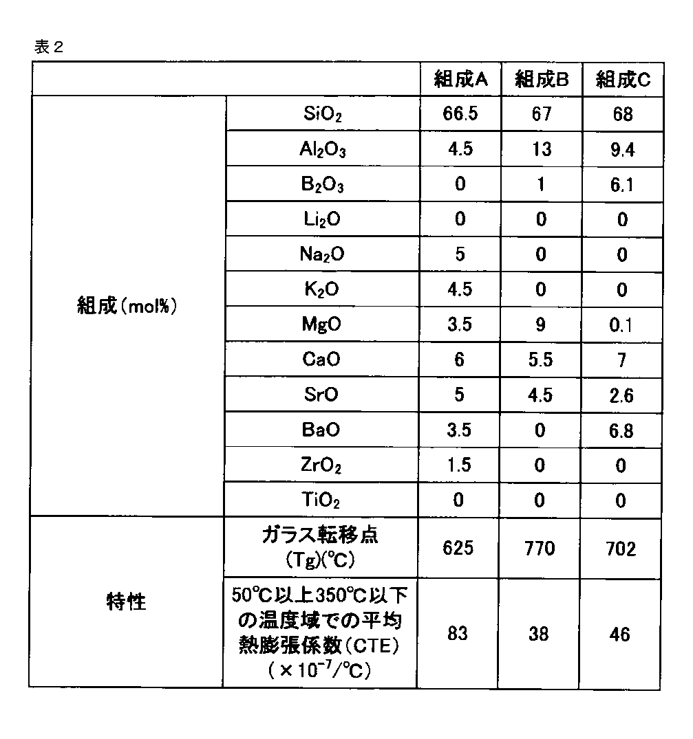
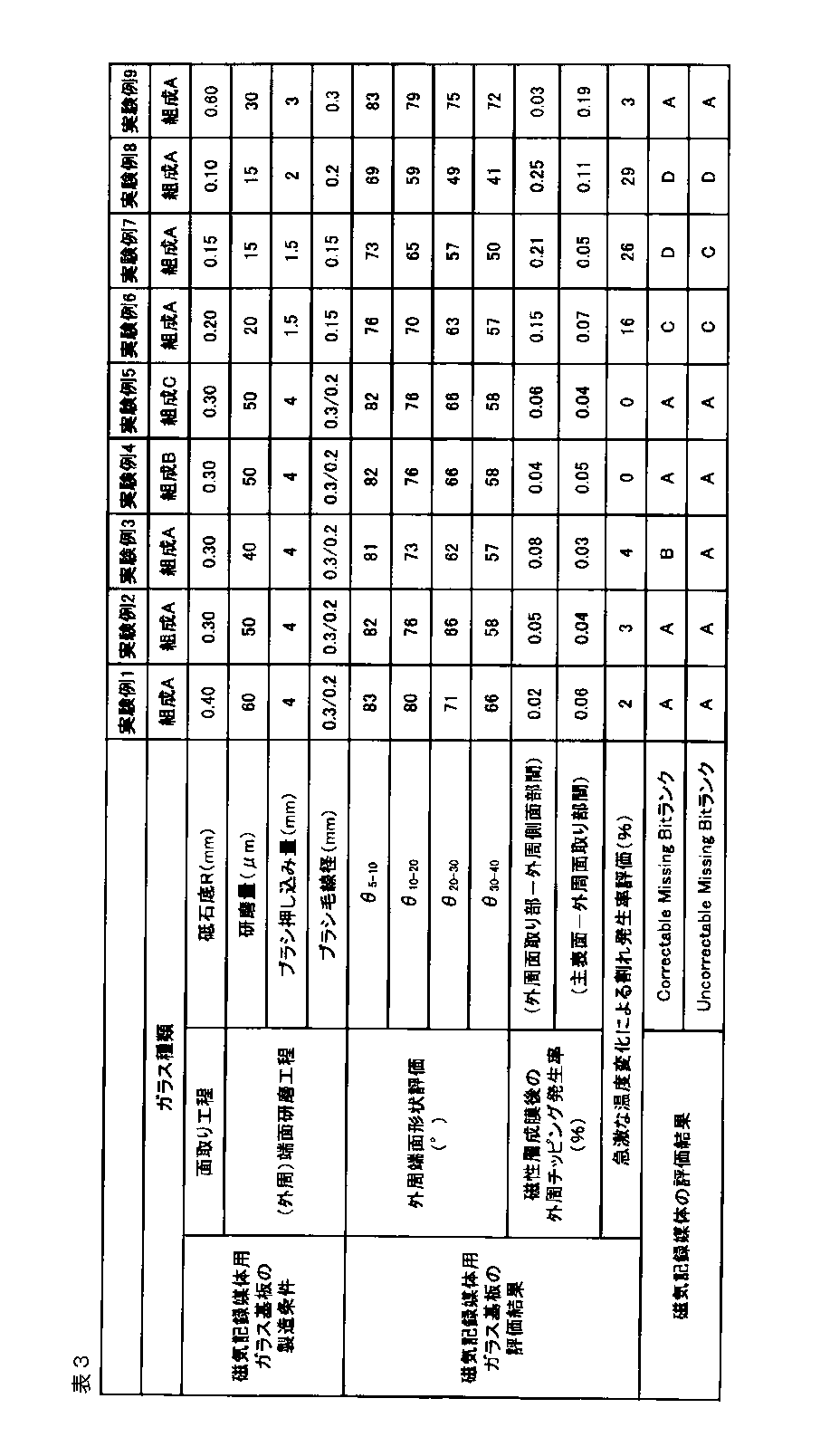
表3に示した結果によると、ガラス基板の外周端面の形状について、θ5-10、θ10-20、θ20-30がそれぞれ81°以上85°以下、69°以上83°以下、52°以上72°以下となっている実験例1~実験例5のガラス基板はいずれも急激な温度変化による割れ発生率が5%以下と低くなっていることを確認できる。
更に、ガラスの平均熱膨張係数が実験例1~3より小さい実験例4および5は、外周端面形状が実験例2と同様だが、急激な温度変化による割れ発生率が実験例2より低く、0%となっている。
これに対して、外周端面の形状のθ5-10およびθ10-20が、上記範囲を満たさない実験例6~8については、急激な温度変化による割れ発生率が15%を超え、非常に高くなっていることを確認できる。なお、外周端面形状のθ5-10およびθ10-20が上記範囲を満たしている実験例9では、急激な温度変化による割れ発生率は3%と比較的低い水準をしめす。
以上の結果から、急激な温度変化による割れ発生率にはガラス基板の外周端面の形状が影響しており、所定の形状とすることで、割れ発生率を抑制できることを確認できる。
また、外周端面の形状が上記形状である実験例1~実験例5のガラス基板については、実験例6~9のガラス基板と比較して、磁性層成膜後の外周チッピング発生率を低く抑制できることを確認できる。
なお、外周端面形状のθ5-10およびθ10-20が上記形状範囲外である実験例6~8では外周側面と外周面取り面との間のチッピングの発生率が高く、外周端面形状のθ20-30が上記範囲外である実験例8および9では、主表面と外周面取り面との間のチッピング発生率が高くなっている。
さらには、実験例1~実験例5のガラス基板については、磁気記録媒体とした際のCorrectable Missing Bit、Uncorrectable Missing Bitのランクについても、実験例6~8のガラス基板よりも高くなることが確認できる。
本発明を特定の態様を参照して詳細に説明したが、本発明の精神と範囲を離れることなく様々な変更および修正が可能であることは、当業者にとって明らかである。なお、本出願は、2015年12月25日付けで出願された日本特許出願(特願2015-255385)および2016年4月18日付けで出願された日本特許出願(特願2016-83175)に基づいており、その全体が引用により援用される。また、ここに引用されるすべての参照は全体として取り込まれる。
10 磁気記録媒体用ガラス基板
121、122 主表面
13 外周端面
131、133 外周面取り部
132 外周側面部
14 内周端面
121、122 主表面
13 外周端面
131、133 外周面取り部
132 外周側面部
14 内周端面
Claims (8)
- 一対の主表面、外周端面、及び内周端面を有するドーナツ形状の磁気記録媒体用ガラス基板であって、
前記外周端面が外周側面部、及び前記外周側面部と前記主表面との間に配置された外周面取り部を有し、
前記一対の主表面と垂直で、かつ前記磁気記録媒体用ガラス基板の中心軸を通る断面において、
前記主表面と平行な軸をX軸とし、前記外周端面の最外周位置のX座標を0、前記外周端面の最外周位置よりも、前記磁気記録媒体用ガラス基板の中心軸側のX座標を正とした場合に、
前記外周端面のうち、X座標が5μmの点と、X座標が10μmの点とを結んだ直線と、前記X軸とが形成する角度が81°以上85°以下、
前記外周端面のうち、X座標が10μmの点と、X座標が20μmの点とを結んだ直線と、前記X軸とが形成する角度が69°以上83°以下、
前記外周端面のうち、X座標が20μmの点と、X座標が30μmの点とを結んだ直線と、前記X軸とが形成する角度が52°以上72°以下、
である磁気記録媒体用ガラス基板。 - 前記外周端面のうち、X座標が5μmの点と、X座標が10μmの点とを結んだ直線と、前記X軸とが形成する角度が81°以上84°以下、
前記外周端面のうち、X座標が10μmの点と、X座標が20μmの点とを結んだ直線と、前記X軸とが形成する角度が75°以上82°以下、
前記外周端面のうち、X座標が20μmの点と、X座標が30μmの点とを結んだ直線と、前記X軸とが形成する角度が55°以上72°以下、
前記外周端面のうち、X座標が30μmの点と、X座標が40μmの点とを結んだ直線と、前記X軸とが形成する角度が51°以上68°以下、
である請求項1に記載の磁気記録媒体用ガラス基板。 - 50℃以上350℃以下の温度域における平均熱膨張係数が50×10-7/℃未満のガラス材料からなる、請求項1または2記載の磁気記録媒体用ガラス基板。
- エネルギーアシスト磁気記録媒体用の磁気記録媒体用ガラス基板である、請求項1乃至3のいずれか一項に記載の磁気記録媒体用ガラス基板。
- モル百分率表示で、SiO2を62%以上74%以下、Al2O3を7%以上18%以下、B2O3を2%以上15%以下含有し、MgOを0以上10%以下、CaO、SrOおよびBaOのいずれか1成分以上を合計で1%以上21%以下含有し、MgO、CaO、SrOおよびBaOの含有量合計が8%以上21%以下、上記7成分の含有量合計が95%以上のガラス材料からなる請求項1乃至4の何れか一項に記載の磁気記録媒体用ガラス基板。
- モル百分率表示でSiO2を62%以上74%以下、Al2O3を7%以上18%以下、B2O3を0以上2%未満、MgO、CaO、SrOおよびBaOの含有量合計が5%以上18%以下、上記7成分の含有量合計が95%以上のガラス材料からなる請求項1乃至4の何れか一項に記載の磁気記録媒体用ガラス基板。
- モル百分率表示で、SiO2を60%以上75%以下、Al2O3を7%以上17%以下、B2O3を0以上2%未満、MgO、CaO、SrOおよびBaOの含有量合計が18%超26%以下、上記7成分の含有量合計が95%以上のガラス材料からなる請求項1乃至4の何れか一項に記載の磁気記録媒体用ガラス基板。
- 請求項1乃至7のいずれか一項に記載の磁気記録媒体用ガラス基板を含む磁気記録媒体。
Applications Claiming Priority (4)
| Application Number | Priority Date | Filing Date | Title |
|---|---|---|---|
| JP2015255385 | 2015-12-25 | ||
| JP2015-255385 | 2015-12-25 | ||
| JP2016083175A JP6020754B1 (ja) | 2015-12-25 | 2016-04-18 | 磁気記録媒体用ガラス基板、磁気記録媒体 |
| JP2016-083175 | 2016-04-18 |
Publications (1)
| Publication Number | Publication Date |
|---|---|
| WO2017110109A1 true WO2017110109A1 (ja) | 2017-06-29 |
Family
ID=57216829
Family Applications (1)
| Application Number | Title | Priority Date | Filing Date |
|---|---|---|---|
| PCT/JP2016/063215 Ceased WO2017110109A1 (ja) | 2015-12-25 | 2016-04-27 | 磁気記録媒体用ガラス基板、磁気記録媒体 |
Country Status (2)
| Country | Link |
|---|---|
| JP (1) | JP6020754B1 (ja) |
| WO (1) | WO2017110109A1 (ja) |
Cited By (1)
| Publication number | Priority date | Publication date | Assignee | Title |
|---|---|---|---|---|
| CN115699893A (zh) * | 2020-06-24 | 2023-02-03 | 中兴通讯股份有限公司 | 用于广播无线通信业务的方法 |
Citations (8)
| Publication number | Priority date | Publication date | Assignee | Title |
|---|---|---|---|---|
| JPH11265506A (ja) * | 1998-03-17 | 1999-09-28 | Asahi Techno Glass Corp | 磁気ディスク用ガラス基板及び磁気ディスク |
| JP2001291229A (ja) * | 2000-04-05 | 2001-10-19 | Asahi Glass Co Ltd | 磁気ディスク用ガラス基板 |
| JP2002342915A (ja) * | 2001-05-14 | 2002-11-29 | Nippon Sheet Glass Co Ltd | 磁気記録媒体用ガラス基板及びその製造方法 |
| JP2011253575A (ja) * | 2010-05-31 | 2011-12-15 | Konica Minolta Opto Inc | 熱アシスト記録媒体用ガラス基板 |
| JP2014160539A (ja) * | 2012-09-28 | 2014-09-04 | Hoya Corp | 磁気ディスク用ガラス基板、磁気ディスク |
| JP2015024954A (ja) * | 2014-09-01 | 2015-02-05 | 旭硝子株式会社 | 基板用ガラスおよびガラス基板 |
| JP2015028827A (ja) * | 2013-06-27 | 2015-02-12 | 旭硝子株式会社 | 磁気記録媒体用無アルカリガラス、および、これを用いた磁気記録媒体用ガラス基板 |
| JP2015027932A (ja) * | 2013-06-27 | 2015-02-12 | 旭硝子株式会社 | 磁気記録媒体用無アルカリガラス、および、これを用いた磁気記録媒体用ガラス基板 |
Family Cites Families (3)
| Publication number | Priority date | Publication date | Assignee | Title |
|---|---|---|---|---|
| JP5413409B2 (ja) * | 2011-06-13 | 2014-02-12 | 旭硝子株式会社 | 支持治具及び磁気記録媒体用ガラス基板の製造方法 |
| JP5126401B1 (ja) * | 2011-09-28 | 2013-01-23 | 旭硝子株式会社 | 磁気記録媒体用ガラス基板 |
| MY168621A (en) * | 2014-03-31 | 2018-11-14 | Hoya Corp | Magnetic-disk glass substrate |
-
2016
- 2016-04-18 JP JP2016083175A patent/JP6020754B1/ja active Active
- 2016-04-27 WO PCT/JP2016/063215 patent/WO2017110109A1/ja not_active Ceased
Patent Citations (8)
| Publication number | Priority date | Publication date | Assignee | Title |
|---|---|---|---|---|
| JPH11265506A (ja) * | 1998-03-17 | 1999-09-28 | Asahi Techno Glass Corp | 磁気ディスク用ガラス基板及び磁気ディスク |
| JP2001291229A (ja) * | 2000-04-05 | 2001-10-19 | Asahi Glass Co Ltd | 磁気ディスク用ガラス基板 |
| JP2002342915A (ja) * | 2001-05-14 | 2002-11-29 | Nippon Sheet Glass Co Ltd | 磁気記録媒体用ガラス基板及びその製造方法 |
| JP2011253575A (ja) * | 2010-05-31 | 2011-12-15 | Konica Minolta Opto Inc | 熱アシスト記録媒体用ガラス基板 |
| JP2014160539A (ja) * | 2012-09-28 | 2014-09-04 | Hoya Corp | 磁気ディスク用ガラス基板、磁気ディスク |
| JP2015028827A (ja) * | 2013-06-27 | 2015-02-12 | 旭硝子株式会社 | 磁気記録媒体用無アルカリガラス、および、これを用いた磁気記録媒体用ガラス基板 |
| JP2015027932A (ja) * | 2013-06-27 | 2015-02-12 | 旭硝子株式会社 | 磁気記録媒体用無アルカリガラス、および、これを用いた磁気記録媒体用ガラス基板 |
| JP2015024954A (ja) * | 2014-09-01 | 2015-02-05 | 旭硝子株式会社 | 基板用ガラスおよびガラス基板 |
Cited By (2)
| Publication number | Priority date | Publication date | Assignee | Title |
|---|---|---|---|---|
| CN115699893A (zh) * | 2020-06-24 | 2023-02-03 | 中兴通讯股份有限公司 | 用于广播无线通信业务的方法 |
| US12376024B2 (en) | 2020-06-24 | 2025-07-29 | Zte Corporation | Method for broadcast radio communication services |
Also Published As
| Publication number | Publication date |
|---|---|
| JP2017120679A (ja) | 2017-07-06 |
| JP6020754B1 (ja) | 2016-11-02 |
Similar Documents
| Publication | Publication Date | Title |
|---|---|---|
| CN102820040B (zh) | 磁记录介质用玻璃基板、及使用该磁记录介质用玻璃基板的磁记录介质 | |
| JP6332321B2 (ja) | 磁気記録媒体用のガラス基板および磁気記録媒体 | |
| JP5915718B1 (ja) | 磁気ディスク用ガラス基板及び磁気ディスク | |
| JP5126401B1 (ja) | 磁気記録媒体用ガラス基板 | |
| JP6360512B2 (ja) | 磁気ディスク用基板、磁気ディスク、磁気ディスク用基板の製造方法、円板状基板の製造方法 | |
| JP5939350B1 (ja) | 磁気記録媒体用ガラス基板、磁気記録媒体 | |
| JP6020754B1 (ja) | 磁気記録媒体用ガラス基板、磁気記録媒体 | |
| JP4780607B2 (ja) | 磁気ディスク用ガラス基板の製造方法、磁気ディスク用ガラス基板、及び磁気ディスクの製造方法。 | |
| JP4860580B2 (ja) | 磁気ディスク用基板及び磁気ディスク | |
| JP5983897B1 (ja) | 磁気ディスク用ガラス基板及び磁気ディスク | |
| JP2013016214A (ja) | Hdd用ガラス基板、hdd用ガラス基板の製造方法、及びhdd用磁気記録媒体 | |
| JP5036323B2 (ja) | 磁気ディスク用ガラス基板の製造方法、磁気ディスクの製造方法およびガラス基板ホルダ | |
| JP5212530B2 (ja) | 磁気記録媒体用ガラス基板、及び、該磁気記録媒体用ガラス基板を用いた磁気記録媒体 | |
| JP5494747B2 (ja) | 磁気記録媒体用ガラス基板の製造方法、及び、磁気記録媒体用ガラス基板 | |
| JP5719785B2 (ja) | 情報記録媒体用ガラス基板、情報記録媒体、および情報記録装置 | |
| JP5348304B2 (ja) | 磁気記録媒体用ガラス基板の製造方法および磁気記録媒体の製造方法 | |
| JP6008060B1 (ja) | 磁気記録媒体用ガラス基板、磁気記録媒体、磁気記録媒体用ガラス基板の製造方法、及び磁気記録媒体用ガラス基板製造装置 | |
| JP4698546B2 (ja) | 磁気ディスク用ガラス基板の製造方法、磁気ディスクの製造方法 | |
| JP2015069684A (ja) | 磁気記録媒体用ガラス基板の製造方法及び磁気記録媒体の製造方法 | |
| JP2010086597A (ja) | 磁気ディスク用ガラス基板の製造方法及び磁気ディスクの製造方法 | |
| JP2013131281A (ja) | 磁気記録媒体用ガラス基板および磁気記録媒体 | |
| WO2012042735A1 (ja) | 情報記録媒体用ガラス基板の製造方法 | |
| JP2015011743A (ja) | 情報記録媒体用ガラス基板の製造方法 |
Legal Events
| Date | Code | Title | Description |
|---|---|---|---|
| 121 | Ep: the epo has been informed by wipo that ep was designated in this application |
Ref document number: 16878012 Country of ref document: EP Kind code of ref document: A1 |
|
| NENP | Non-entry into the national phase |
Ref country code: DE |
|
| 122 | Ep: pct application non-entry in european phase |
Ref document number: 16878012 Country of ref document: EP Kind code of ref document: A1 |