WO2017110075A1 - 管部材 - Google Patents
管部材 Download PDFInfo
- Publication number
- WO2017110075A1 WO2017110075A1 PCT/JP2016/005167 JP2016005167W WO2017110075A1 WO 2017110075 A1 WO2017110075 A1 WO 2017110075A1 JP 2016005167 W JP2016005167 W JP 2016005167W WO 2017110075 A1 WO2017110075 A1 WO 2017110075A1
- Authority
- WO
- WIPO (PCT)
- Prior art keywords
- main body
- rib
- ribs
- tube main
- pipe member
- Prior art date
- Legal status (The legal status is an assumption and is not a legal conclusion. Google has not performed a legal analysis and makes no representation as to the accuracy of the status listed.)
- Ceased
Links
Images


Classifications
-
- F—MECHANICAL ENGINEERING; LIGHTING; HEATING; WEAPONS; BLASTING
- F02—COMBUSTION ENGINES; HOT-GAS OR COMBUSTION-PRODUCT ENGINE PLANTS
- F02M—SUPPLYING COMBUSTION ENGINES IN GENERAL WITH COMBUSTIBLE MIXTURES OR CONSTITUENTS THEREOF
- F02M35/00—Combustion-air cleaners, air intakes, intake silencers, or induction systems specially adapted for, or arranged on, internal-combustion engines
- F02M35/10—Air intakes; Induction systems
-
- F—MECHANICAL ENGINEERING; LIGHTING; HEATING; WEAPONS; BLASTING
- F16—ENGINEERING ELEMENTS AND UNITS; GENERAL MEASURES FOR PRODUCING AND MAINTAINING EFFECTIVE FUNCTIONING OF MACHINES OR INSTALLATIONS; THERMAL INSULATION IN GENERAL
- F16L—PIPES; JOINTS OR FITTINGS FOR PIPES; SUPPORTS FOR PIPES, CABLES OR PROTECTIVE TUBING; MEANS FOR THERMAL INSULATION IN GENERAL
- F16L11/00—Hoses, i.e. flexible pipes
- F16L11/04—Hoses, i.e. flexible pipes made of rubber or flexible plastics
- F16L11/11—Hoses, i.e. flexible pipes made of rubber or flexible plastics with corrugated wall
- F16L11/115—Hoses, i.e. flexible pipes made of rubber or flexible plastics with corrugated wall having reinforcements not embedded in the wall
-
- F—MECHANICAL ENGINEERING; LIGHTING; HEATING; WEAPONS; BLASTING
- F16—ENGINEERING ELEMENTS AND UNITS; GENERAL MEASURES FOR PRODUCING AND MAINTAINING EFFECTIVE FUNCTIONING OF MACHINES OR INSTALLATIONS; THERMAL INSULATION IN GENERAL
- F16L—PIPES; JOINTS OR FITTINGS FOR PIPES; SUPPORTS FOR PIPES, CABLES OR PROTECTIVE TUBING; MEANS FOR THERMAL INSULATION IN GENERAL
- F16L27/00—Adjustable joints; Joints allowing movement
- F16L27/10—Adjustable joints; Joints allowing movement comprising a flexible connection only
- F16L27/107—Adjustable joints; Joints allowing movement comprising a flexible connection only the ends of the pipe being interconnected by a flexible sleeve
- F16L27/11—Adjustable joints; Joints allowing movement comprising a flexible connection only the ends of the pipe being interconnected by a flexible sleeve the sleeve having the form of a bellows with multiple corrugations
- F16L27/111—Adjustable joints; Joints allowing movement comprising a flexible connection only the ends of the pipe being interconnected by a flexible sleeve the sleeve having the form of a bellows with multiple corrugations the bellows being reinforced
Definitions
- the present invention relates to a pipe member used when connecting, for example, a duct for high pressure.
- a turbo duct for sending air sucked by a turbine to an intercooler realizes flexibility that can cope with a difference in the size of the turbo duct and high rigidity that suppresses expansion due to high pressure. Therefore, it is connected by a connection tube having a bellows structure.
- a connection tube having a bellows structure For example, an engine air duct hose described in Patent Document 1 below has reinforcing ribs that connect the bellows raised portions of the bellows structure. High rigidity is realized by this reinforcing rib.
- the present invention has been proposed in view of such circumstances. That is, it aims at providing the pipe member which can implement
- a pipe member according to the present invention is a pipe member provided with a bellows-shaped pipe body part in which ridges and sinking parts are alternately connected, and connects the adjacent ridges to each other.
- the rib to perform is inclined with respect to the axial direction of the tube main body.
- a plurality of the ribs are formed on the outer surface of the pipe main body in the axial direction of the pipe main body, and a plurality of ribs are formed at intervals in the circumferential direction of the pipe main body. It is characterized by that.
- a plurality of the ribs are formed in the axial direction of the pipe main body part and a plurality of ribs are formed in the circumferential direction of the pipe main body part on the inner surface of the pipe main body part. It is characterized by that.
- the pipe member which concerns on this invention is the said rib formed between the said ribs formed between the outer surface side protruding parts in the outer surface of the said tube main body part, and the inner surface side protruding parts in the inner surface of the said tube main body part. Are arranged so as to be shifted in the circumferential direction of the tube main body.
- the tube member according to the present invention is characterized in that the rib is formed lower than the height of the raised portion.
- the tube member according to the present invention is characterized in that the center of the rib is formed thinner than the end connected to the raised portion.
- the tube member according to the present invention is a tube member provided with a bellows-shaped tube body portion in which ridges and sinking portions are alternately connected, and the ribs connecting the adjacent ridges are adjacent to the ridges.
- the one end portion connected to one side of the portions and the other end portion connected to the other side of the adjacent raised portions, the one end portion and the other end portion are the tube body portion It is characterized by being shifted in the circumferential direction.
- the pipe member according to the present invention has the above-described configuration. That is, since the rib is inclined with respect to the axial direction of the tube main body, an external force from the axial direction is applied in a direction intersecting the rib. Therefore, the rib is easy to bend in the inclined direction, and excellent flexibility can be realized. In addition, when stress acts on the rib against an external force that is to be expanded by high pressure, adjacent ribs are wide in the circumferential direction because the rib is inclined with respect to the axial direction of the tube main body. It can be secured with a high rigidity.
- the rib is formed in the same direction as the axial direction of the tube main body, the external force from the axial direction is applied on the same straight line as the rib, so it is difficult to bend.
- the rib is in the same direction as the axial direction of the tube main body, the volume of the rib is small compared to the case where the rib is inclined, and the range in which the adjacent raised portions are connected to each other is narrow in the circumferential direction. High rigidity cannot be realized.
- a plurality of ribs are formed on the outer surface (or inner surface) of the tube main body portion in the axial direction of the tube main body portion, and a plurality of ribs are formed at intervals in the circumferential direction of the tube main body portion. Yes. Therefore, excellent flexibility and high rigidity can be realized with respect to the entire tube main body.
- the rib formed between the outer surface-side raised portions on the outer surface of the tube main body portion and the rib formed between the inner surface-side raised portions on the inner surface of the tube main body portion are They are displaced in the circumferential direction of the main body.
- the positions of the ribs on the inner surface and the outer surface can be appropriately selected according to the molding method.
- the rib is formed lower than the height of the raised portion. That is, moderate rigidity can be realized by opening between the vertices of the raised portions.
- the center of the rib is formed thinner than the end connected to the raised portion. With this configuration, the rib is easy to bend at the center that is thinner than the end portion, and excellent flexibility can be realized.
- a rib that connects adjacent raised portions is connected to one side of adjacent raised portions, and the other end connected to the other side of adjacent raised portions.
- the one end part and the other end part are shifted in the circumferential direction of the pipe body part.
- the rib since each end of the rib is displaced in the circumferential direction, the rib is inclined with respect to the raised portion, and thus an external force is applied in a direction intersecting the rib. Therefore, the rib is easy to bend in the inclined direction, and excellent flexibility can be realized.
- the adjacent ridges are connected in a wide range in the circumferential direction because the rib is inclined with respect to the ridge. High rigidity can be realized.
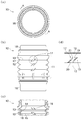
- FIG. 1 shows an external appearance of a pipe member according to an embodiment of the present invention, wherein (a) is a top view seen from above in the axial direction, (b) is a side view seen from the side, and (c) is a longitudinal section taken along AA.
- FIG. 4D is an enlarged view of the rib.
- the side surface of the pipe member which concerns on embodiment of this invention is shown, (a) is a fragmentary longitudinal cross-sectional view, (b) is a cross-sectional enlarged view of a rib. It is the use condition figure by which the outline of the use condition of the pipe member concerning the embodiment of the present invention was shown.
- FIG. 1 and 2 show the appearance of a tube member 10 according to an embodiment of the present invention.
- the pipe member 10 formed of a resin such as a thermoplastic elastomer has a cylindrical shape as shown in FIGS. 1 and 2, and ridges and sinking parts parallel to each other are alternately connected in the axial direction.
- An accordion-shaped tube main body portion 11 is provided. That is, since the tube main body 11 is a cylinder having a bellows-shaped side surface, the raised portion and the sink portion are formed on the outer surface and the inner surface, respectively, An inner surface side sedimentation portion 15 and an inner surface side raised portion 14 which are the inner surface side of the tube main body portion 11 are formed inside the sedimentation portion 13.
- Each of the upper and lower ends of the tube main body 11 is provided with a connection portion 16 formed by an annular groove or the like.
- the longitudinal direction of the cylindrical tube member 10 is defined as the axial direction
- the circumferential direction of the tube member 10 is defined as the circumferential direction.
- One of the axial directions is the upper side, and the other is the lower side.
- the pipe main body 11 has ribs formed between adjacent ridges 12 and 14. More specifically, the outer surface ribs 12 adjacent to each other and the outer ribs 17 formed on the outer surface settling part 13 are connected to the adjacent inner surface protruding parts 14 and the inner surface settling part 15 is formed. There are inner ribs 18.
- the outer surface ribs 17 are formed on the outer surface of the tube main body portion 11 so as to be aligned on the same line in the axial direction and between the outer surface side raised portions 12, and a group of the plurality of outer surface ribs 17 is equally spaced in the circumferential direction. It is formed in all directions with a gap.
- the inner surface ribs 18 are formed on the inner surface of the tube main body 11 on the same line in the axial direction and formed between the inner surface side raised portions 14, and a group of the plurality of inner surface ribs 18 is formed in the circumferential direction. Are formed in four directions with an equal spacing.
- the outer ribs 17 and the inner ribs 18 are arranged at regular intervals in the circumferential direction. Specifically, the outer rib 17 is formed by dividing the outer peripheral surface of 360 degrees into four parts every 90 degrees, and similarly, the inner rib 18 is divided into four parts of the inner peripheral surface of 360 degrees every 90 degrees. Each is formed. The outer surface rib 17 and the inner surface rib 18 are shifted by 45 degrees in the circumferential direction, and the inner surface rib 17 and the outer surface rib 18 are alternately arranged in the circumferential direction. In addition, the number of ribs, arrangement
- FIG. 3 shows a cross section of the outer rib 17 of the pipe member 10 according to the embodiment of the present invention.
- the outer surface rib 17 and the inner surface rib 18 are the same structures, only the outer surface rib 17 is demonstrated in the following description.
- the outer rib 17 is inclined with respect to the axial direction. More specifically, as shown in FIG. 2D, the outer rib 17 is formed as one end connected to the upper outer bulge 12 on one side in the adjacent outer bulge 12.
- the lower end 20 as the other end connected to the upper end 19 and the lower outer surface raised portion 12 which is the other side, and the central portion where these ends 19 and 20 are connected at the outer settling portion 13 21.
- the upper end portion 19 and the lower end portion 20 are displaced in the circumferential direction and are connected to the upper and lower outer surface side raised portions 12 at an acute angle, so that the outer surface rib 17 is inclined with respect to the axial direction.
- the rib should just incline with respect to each inclined ridge part.
- the central portion 21 is formed thinner than the width in the circumferential direction of the end portions 19 and 20, and the end portions 19 and 20 are formed wider than the central portion 21.
- the outer surface ribs 17 are formed lower than the height of the outer surface side raised portions 12, and the vertices of the outer surface side raised portions 12 are opened.
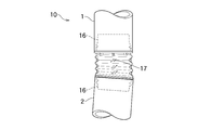
- FIG. 4 shows an outline of a usage state of the pipe member 10 according to the embodiment of the present invention.
- connection part 16 is arbitrary and is suitably changed according to the connection structure of the connection part 16 and each duct hose 1 and 2.
- the connection structure may be, for example, mechanical fitting, welding, pressure bonding with a binding band, or the like.
- the adjacent outer surface side raised portions 12 are connected to each other, the outer surface ribs 17 formed on the outer surface side settling portion 13 and the adjacent inner surface side raised portions 14 are connected to each other and the inner surface.
- Inner ribs 18 formed on the side sedimentation portion 15 are formed.
- Each of the ribs 17 and 18 includes an upper end portion 19 connected to the upper outer surface side raised portion 12 (or the inner surface side raised portion 14) and a lower portion at the adjacent outer surface side raised portion 12 (or the inner surface side raised portion 14).
- a lower end portion 20 connected to the outer surface side raised portion 12 (or the inner surface side raised portion 14) and a central portion where these end portions 19 and 20 are connected to each other at the outer surface side settling portion 13 (or the inner surface side settling portion 15). 21.
- the upper end portion 19 and the lower end portion 20 are displaced in the circumferential direction, and are connected to the upper and lower outer surface-side raised portions 12 (or the inner surface-side raised portion 14) at an acute angle. Inclined with respect to direction.
- each rib 17 and 18 is easy to bend in the direction which inclines, and can implement
- the outer surface ribs 17 and the inner surface ribs 18 are aligned on the same line in the axial direction on the outer surface and the inner surface of the tube main body portion 11, and the outer surface side raised portions 12 and the inner surface side raised portions 14 are aligned.
- Each group of the plurality of ribs 17 and 18 is formed in four directions at equal intervals in the circumferential direction. Therefore, it is possible to achieve excellent flexibility and high rigidity uniformly and uniformly with respect to the entire tube body 11.
- the outer surface rib 17 and the inner surface rib 18 are formed by dividing the outer peripheral surface and the inner peripheral surface of 360 degrees into four parts every 90 degrees, and are shifted by 45 degrees in the circumferential direction. And outer ribs 18 are alternately arranged in the circumferential direction.
- the position of each rib 17 and 18 can be suitably selected according to a shaping
- each rib 17 and 18 is formed lower than the height of each raised part 12 and 14, and the space
- the ribs 17 and 18 are formed such that the central portion 21 is thinner than the width in the circumferential direction of the end portions 19 and 20, and the widths of the end portions 19 and 20 are wider than the central portion 21. Is formed. With this configuration, the ribs 17 and 18 can be easily bent at the central portion 21 that is thinner than the end portions 19 and 20, and can realize excellent flexibility.
- connection structures such as liquid piping and pressure hoses.
Landscapes
- Engineering & Computer Science (AREA)
- General Engineering & Computer Science (AREA)
- Mechanical Engineering (AREA)
- Chemical & Material Sciences (AREA)
- Combustion & Propulsion (AREA)
- Rigid Pipes And Flexible Pipes (AREA)
Abstract
優れた可撓性と高い剛性とを実現することができる管部材を提供する。 管部材(10)は、隣接する外面側隆起部(12)同士を連接する外側リブ(17)が、隣接する外面側隆起部(12)同士の一方側に連接された上端部(19)と、隣接する外面側隆起部(12)同士の他方側に連接された下端部(20)とから構成され、上端部(19)と下端部(20)とが管本体部(11)の周方向においてずれて形成されたことで、外面リブ(17)が軸方向に対して傾斜している。
Description
本発明は、例えば高圧用のダクトなどを接続する際に用いられる管部材に関するものである。
従来、例えば自動車の内燃機関などにおいて、タービンで吸気された空気をインタークーラーに送るためのターボダクトは、ターボダクトの寸法の違いに対応できる可撓性と、高圧による膨張を抑える高い剛性とを実現するため、蛇腹構造の接続管によって接続されている。例えば、下記特許文献1に記載されたエンジン用エアダクトホースは、蛇腹構造のうちの蛇腹隆起部同士を連結する補強リブが形成されている。この補強リブによって、高い剛性が実現されている。
しかし、特許文献1に記載されたエンジン用エアダクトホースは、上記したとおり補強リブによって高い剛性が実現されるが、一方で、伸縮し、または曲げられる際の可撓性が、補強リブによって損なわれる場合がある。
本発明は、この様な実情に鑑みて提案されたものである。すなわち、優れた可撓性と高い剛性とを実現することができる管部材の提供を目的とする。
上記目的を達成するために、本発明に係る管部材は、隆起部と沈降部とが交互に連接された蛇腹形状の管本体部が備えられた管部材において、隣接する前記隆起部同士を連接するリブが、前記管本体部の軸方向に対して傾斜した、ことを特徴とする。
本発明に係る管部材は、前記管本体部の外面において、前記リブが、前記管本体部の軸方向に複数形成されると共に、前記管本体部の周方向に間隔を空けて複数形成された、ことを特徴とする。
本発明に係る管部材は、前記管本体部の内面において、前記リブが、前記管本体部の軸方向に複数形成されると共に、前記管本体部の周方向に間隔を空けて複数形成された、ことを特徴とする。
本発明に係る管部材は、前記管本体部の外面における外面側隆起部同士の間に形成された前記リブと、前記管本体部の内面における内面側隆起部同士の間に形成された前記リブとが、前記管本体部の周方向においてずれて配置された、ことを特徴とする。
本発明に係る管部材は、前記リブが、前記隆起部の高さよりも低く形成された、ことを特徴とする。
本発明に係る管部材は、前記リブの中央が、前記隆起部に連接された端部よりも薄く形成された、ことを特徴とする。
本発明に係る管部材は、隆起部と沈降部とが交互に連接された蛇腹形状の管本体部が備えられた管部材において、隣接する前記隆起部同士を連接するリブが、隣接する前記隆起部同士の一方側に連接された一方端部と、隣接する前記隆起部同士の他方側に連接された他方端部とから構成され、前記一方端部と前記他方端部とが前記管本体部の周方向においてずれている、ことを特徴とする。
本発明に係る管部材は上記した構成である。すなわち、リブが管本体部の軸方向に対して傾斜しているため、軸方向からの外力が、リブと交差する方向に加えられる。そのため、リブは、傾斜している方向に撓みやすく、優れた可撓性を実現することができる。また、高圧によって膨張させようとする外力に対してリブに応力が作用する際、リブが管本体部の軸方向に対して傾斜している分、隣接する隆起部同士が、周方向に広い範囲で繋ぎ留められ、高い剛性を実現することができる。
なお、仮にリブが管本体部の軸方向と同じ向きに形成されている場合、軸方向からの外力が、リブと同一直線上に加えられるため、撓み辛い。また、リブが管本体部の軸方向と同じ向きである分、リブを傾斜させた場合と比較してリブの体積が少なく、隣接する隆起部同士が繋ぎ留められる範囲が周方向において狭いため、高い剛性を実現することができない。
本発明に係る管部材は、管本体部の外面(または内面)において、リブが、管本体部の軸方向に複数形成されると共に、管本体部の周方向に間隔を空けて複数形成されている。したがって、管本体部の全体に対して優れた可撓性と、高い剛性を実現することができる。
本発明に係る管部材は、管本体部の外面における外面側隆起部同士の間に形成されたリブと、管本体部の内面における内面側隆起部同士の間に形成されたリブとが、管本体部の周方向においてずれて配置されている。このように、内面および外面におけるリブの位置を、成形方法に応じて適宜選択することができる。
本発明に係る管部材は、リブが隆起部の高さよりも低く形成されている。すなわち、隆起部の頂点同士の間を開放させることで、適度な剛性を実現することができる。
本発明に係る管部材は、リブの中央が、隆起部に連接された端部よりも薄く形成されている。この構成により、リブは、端部よりも薄い中央が撓みやすく、優れた可撓性を実現することができる。
本発明に係る管部材は、隣接する隆起部同士を連接するリブが、隣接する隆起部同士の一方側に連接された一方端部と、隣接する隆起部同士の他方側に連接された他方端部とから構成され、一方端部と他方端部とが管本体部の周方向においてずれている。すなわち、リブの各端部が周方向にずれていることから、リブが隆起部に対して傾斜しているため、外力がリブと交差する方向に加えられる。そのため、リブは、傾斜している方向に撓みやすく、優れた可撓性を実現することができる。また、高圧によって膨張させようとする外力に対してリブに応力が作用する際、リブが隆起部に対して傾斜している分、隣接する隆起部同士が、周方向に広い範囲で繋ぎ留められ、高い剛性を実現することができる。
以下に、本発明の実施形態に係る管部材を図面に基づいて説明する。図1および図2は、本発明の実施形態に係る管部材10の外観が示されている。
例えば、熱可塑性エラストマーなどの樹脂で成形された管部材10は、図1および図2に示されているとおり、円筒状であり、互いに平行な隆起部と沈降部とが軸方向に交互に連接された蛇腹形状の管本体部11が備えられている。すなわち、管本体部11は側面が蛇腹形状の円筒であるため、隆起部および沈降部が外面および内面にそれぞれ形成されており、管本体部11の外面側である外面側隆起部12および外面側沈降部13の内側に、管本体部11の内面側である内面側沈降部15および内面側隆起部14がそれぞれ形成されている。また、管本体部11の上下両端のそれぞれは、環状の溝などによって形成された接続部16が備えられている。なお、以下の説明では、図1を基準として、円筒状の管部材10の長手方向を軸方向とし、管部材10の円周方向を周方向とする。また、軸方向の一方を上方とし、他方を下方とする。
管本体部11は、隣接する各隆起部12同士、14同士の間にリブが形成されている。詳説すれば、隣接する外面側隆起部12同士を連接すると共に外面側沈降部13に形成された外面リブ17と、隣接する内面側隆起部14同士を連接すると共に内面側沈降部15に形成された内面リブ18とがある。外面リブ17は、管本体部11の外面において、軸方向に同一線上に揃えられて各外面側隆起部12同士の間に形成され、この複数の外面リブ17の一群が、周方向に等しく間隔を空けて四方に形成されている。同様に、内面リブ18は、管本体部11の内面において、軸方向に同一線上に揃えられて各内面側隆起部14同士の間に形成され、この複数の内面リブ18の一群が、周方向に等しく間隔を空けて四方に形成されている。
外面リブ17と内面リブ18とは、周方向において等間隔にずれて配置されている。詳説すれば、外面リブ17は、360度の外周面を4分割して90度ごとにそれぞれ形成され、同様に、内面リブ18は、360度の内周面を4分割して90度ごとにそれぞれ形成されている。外面リブ17と内面リブ18とは、周方向に45度ずれており、内面リブ17と外面リブ18とが周方向において交互に配置されている。なお、リブの数や、配置および間隔は任意である。また、リブは、外面のみ、または内面のみに形成されていてもよい。
ここで、リブについて、図面に基づいてさらに詳説する。図3は、本発明の実施形態に係る管部材10の外面リブ17の断面が示されている。なお、外面リブ17と内面リブ18とは同じ構成であるため、以下の説明では、外面リブ17についてのみ説明する。
図2および図3に示されているとおり、外面リブ17は軸方向に対して傾斜している。詳説すれば、図2(d)に示されているとおり、外面リブ17は、隣接する外面側隆起部12において、一方側である上方の外面側隆起部12に連接された一方端部としての上端部19、および他方側である下方の外面側隆起部12に連接された他方端部としての下端部20と、この各端部19,20同士が外面側沈降部13において連接された中央部21とから形成されている。
上端部19と下端部20とは、周方向にずれており、上下の外面側隆起部12に対して鋭角に連接されているため、外面リブ17は軸方向に対して傾斜している。なお、各隆起部が軸方向に対して傾斜した螺旋状である場合、この傾斜した各隆起部に対してリブが傾斜していればよい。
中央部21は、各端部19,20の周方向における幅よりも薄く形成され、各端部19,20は、中央部21よりも幅が広く形成されている。
外面リブ17は、図3(b)に示されているとおり、外面側隆起部12の高さよりも低く形成され、外面側隆起部12の頂点同士の間が開放されている。
上記のとおり形成された管部材10は、ダクトホースに接続される。ここで、管部材10をダクトホースに接続した状態を図面に基づいて説明する。図4は、本発明の実施形態に係る管部材10の使用状態の概略が示されている。
図4に示されているとおり、接続部16にアッパーダクトホース1およびロウアーダクトホース2がそれぞれ嵌合して接続され、このことによって各ダクトホース1,2が管部材10を介して連結される。なお、接続部16の形状は任意であり、接続部16と各ダクトホース1,2との接続構造に応じて適宜変更される。接続構造は、例えば、機械式の嵌合、溶着、結束バンドによる圧着などであってもよい。
各ダクト1,2の寸法が多少異なる場合であっても、管部材10が撓むことで寸法の違いに対応することができる。また、各リブ17,18によって、高圧による膨張が抑えられる。
次に、本実施形態の効果を説明する。
上記したとおり、本実施形態によれば、隣接する外面側隆起部12同士を連接すると共に外面側沈降部13に形成された外面リブ17と、隣接する内面側隆起部14同士を連接すると共に内面側沈降部15に形成された内面リブ18とが形成されている。各リブ17,18は、隣接する外面側隆起部12(または内面側隆起部14)において、上方の外面側隆起部12(または内面側隆起部14)に連接された上端部19、および下方の外面側隆起部12(または内面側隆起部14)に連接された下端部20と、この各端部19,20同士が外面側沈降部13(または内面側沈降部15)において連接された中央部21とから形成されている。上端部19と下端部20とは、周方向にずれており、上下の外面側隆起部12(または内面側隆起部14)に対して鋭角に連接されているため、各リブ17,18は軸方向に対して傾斜している。
すなわち、各端部19,20が周方向にずれ、各リブ17,18が軸方向に対して傾斜しているため、軸方向からの外力が、各リブ17,18と交差する方向に加えられる。そのため、各リブ17,18は、傾斜している方向に撓みやすく、優れた可撓性を実現することができる。また、高圧によって膨張させようとする外力に対して各リブ17,18に応力が作用する際、各リブ17,18が軸方向に対して傾斜している分、隣接する外面側隆起部12(または内面側隆起部14)同士が、周方向に広い範囲で繋ぎ留められ、高い剛性を実現することができる。
本実施形態によれば、外面リブ17および内面リブ18は、管本体部11の外面および内面において、軸方向に同一線上に揃えられて各外面側隆起部12同士および各内面側隆起部14同士の間に形成され、この複数の各リブ17,18の各一群が、周方向に等しく
間隔を空けて四方に形成されている。したがって、管本体部11の全体に対して、均一に万遍なく優れた可撓性と、高い剛性を実現することができる。
間隔を空けて四方に形成されている。したがって、管本体部11の全体に対して、均一に万遍なく優れた可撓性と、高い剛性を実現することができる。
本実施形態によれば、外面リブ17および内面リブ18は、360度の外周面および内周面を4分割して90度ごとにそれぞれ形成され、周方向に45度ずれており、内面リブ17と外面リブ18とが周方向において交互に配置されている。このように、各リブ17,18の位置を、成形方法に応じて適宜選択することができる。
本実施形態によれば、各リブ17,18は、各隆起部12,14の高さよりも低く形成され、外面側隆起部12の頂点同士、および内面側隆起部14の頂点同士の間が開放されている。すなわち、各隆起部12,14の各頂点同士の間を開放させることで、過度な剛性を抑えて適度な剛性を実現することができる。
本実施形態によれば、各リブ17,18は、中央部21が各端部19,20の周方向における幅よりも薄く形成され、各端部19,20の幅が中央部21よりも広く形成されている。この構成により、各リブ17,18は、各端部19,20よりも薄い中央部21が撓みやすく、優れた可撓性を実現することができる。
以上、本発明の実施形態を詳述したが、本発明は上記実施形態に限定されるものではない。そして本発明は、特許請求の範囲に記載された事項を逸脱することがなければ、種々の設計変更を行うことが可能である。例えば、液体類の配管や、耐圧ホースなどの接続構造に用いられる。
1 アッパーダクトホース
2 ロウアーダクトホース
10 管部材
11 管本体部
12 外面側隆起部(隆起部)
13 外面側沈降部(沈降部)
14 内面側隆起部(隆起部)
15 内面側沈降部(沈降部)
16 接続部
17 外面リブ(リブ)
18 内面リブ(リブ)
19 上端部(一方端部)
20 下端部(他方端部)
21 中央部
2 ロウアーダクトホース
10 管部材
11 管本体部
12 外面側隆起部(隆起部)
13 外面側沈降部(沈降部)
14 内面側隆起部(隆起部)
15 内面側沈降部(沈降部)
16 接続部
17 外面リブ(リブ)
18 内面リブ(リブ)
19 上端部(一方端部)
20 下端部(他方端部)
21 中央部
Claims (7)
- 隆起部と沈降部とが交互に連接された蛇腹形状の管本体部が備えられた管部材において、
隣接する前記隆起部同士を連接するリブが、前記管本体部の軸方向に対して傾斜して備えられた、
ことを特徴とする管部材。 - 前記管本体部の外面において、前記リブが、前記管本体部の軸方向に複数形成されると共に、前記管本体部の周方向に間隔を空けて複数形成された、
ことを特徴とする請求項1に記載された管部材。 - 前記管本体部の内面において、前記リブが、前記管本体部の軸方向に複数形成されると共に、前記管本体部の周方向に間隔を空けて複数形成された、
ことを特徴とする請求項1または請求項2に記載された管部材。 - 前記管本体部の外面における外面側隆起部同士の間に形成された前記リブと、前記管本体部の内面における内面側隆起部同士の間に形成された前記リブとが、前記管本体部の周方向においてずれて配置された、
ことを特徴とする請求項1から請求項3のいずれか1項に記載された管部材。 - 前記リブが、前記隆起部の高さよりも低く形成された、
ことを特徴とする請求項1から請求項4のいずれか1項に記載された管部材。 - 前記リブの中央が、前記隆起部に連接された端部よりも薄く形成された、
ことを特徴とする請求項1から請求項5のいずれか1項に記載された管部材。 - 隆起部と沈降部とが交互に連接された蛇腹形状の管本体部が備えられた管部材において、
隣接する前記隆起部同士を連接するリブが、隣接する前記隆起部同士の一方側に連接された一方端部と、隣接する前記隆起部同士の他方側に連接された他方端部とから構成され、
前記一方端部と前記他方端部とが前記管本体部の周方向においてずれている、
ことを特徴とする管部材。
Applications Claiming Priority (2)
| Application Number | Priority Date | Filing Date | Title |
|---|---|---|---|
| JP2015249538A JP6636316B2 (ja) | 2015-12-22 | 2015-12-22 | 管部材 |
| JP2015-249538 | 2015-12-22 |
Publications (1)
| Publication Number | Publication Date |
|---|---|
| WO2017110075A1 true WO2017110075A1 (ja) | 2017-06-29 |
Family
ID=59089935
Family Applications (1)
| Application Number | Title | Priority Date | Filing Date |
|---|---|---|---|
| PCT/JP2016/005167 Ceased WO2017110075A1 (ja) | 2015-12-22 | 2016-12-16 | 管部材 |
Country Status (2)
| Country | Link |
|---|---|
| JP (1) | JP6636316B2 (ja) |
| WO (1) | WO2017110075A1 (ja) |
Families Citing this family (1)
| Publication number | Priority date | Publication date | Assignee | Title |
|---|---|---|---|---|
| DE102018206615A1 (de) * | 2018-04-27 | 2019-10-31 | Mahle International Gmbh | Rohrkörper für eine Frischluftanlage einer Brennkraftmaschine |
Citations (8)
| Publication number | Priority date | Publication date | Assignee | Title |
|---|---|---|---|---|
| JPS538044B2 (ja) * | 1972-01-03 | 1978-03-24 | ||
| JPS57190571A (en) * | 1981-05-20 | 1982-11-24 | Terumo Corp | Bellow pipe with reduced extensibility for breathing apparatus |
| JPS60146987A (ja) * | 1983-12-30 | 1985-08-02 | 島田 忠明 | 多角形伸縮管 |
| JPS6288893A (ja) * | 1985-10-11 | 1987-04-23 | 市川 博夫 | 長さを可変とした筒状体 |
| JPH01130019U (ja) * | 1988-02-29 | 1989-09-05 | ||
| JPH08270843A (ja) * | 1995-03-28 | 1996-10-15 | Matsushita Electric Works Ltd | 可撓性波形管 |
| EP1231424A1 (en) * | 2001-02-13 | 2002-08-14 | OFFICINE METALLURGICHE G. CORNAGLIA S.p.A. | "Pipe comprising a flexible portion in the form of a bellows sleeve" |
| WO2011073047A1 (de) * | 2009-12-19 | 2011-06-23 | Mahle International Gmbh | Wellrohr, rohr und frischluftanlage |
Family Cites Families (5)
| Publication number | Priority date | Publication date | Assignee | Title |
|---|---|---|---|---|
| US3578777A (en) * | 1969-06-11 | 1971-05-18 | Koppy Tool Corp | Corrugated tubing |
| JPS59150931U (ja) * | 1983-03-29 | 1984-10-09 | 橋本フオ−ミング工業株式会社 | 内燃機関の排気系用フレキシブルチユ−ブ |
| JP4606275B2 (ja) * | 2005-08-23 | 2011-01-05 | 矢崎総業株式会社 | コルゲートチューブを用いたハーネス配索構造 |
| US7785514B2 (en) * | 2006-05-18 | 2010-08-31 | Mccarthy Peter T | Snorkels, flexible tubes, mouthpieces and methods |
| US7914231B2 (en) * | 2007-03-02 | 2011-03-29 | Infiltrator Systems, Inc. | Leaching chamber having a diagonally ribbed top |
-
2015
- 2015-12-22 JP JP2015249538A patent/JP6636316B2/ja not_active Expired - Fee Related
-
2016
- 2016-12-16 WO PCT/JP2016/005167 patent/WO2017110075A1/ja not_active Ceased
Patent Citations (8)
| Publication number | Priority date | Publication date | Assignee | Title |
|---|---|---|---|---|
| JPS538044B2 (ja) * | 1972-01-03 | 1978-03-24 | ||
| JPS57190571A (en) * | 1981-05-20 | 1982-11-24 | Terumo Corp | Bellow pipe with reduced extensibility for breathing apparatus |
| JPS60146987A (ja) * | 1983-12-30 | 1985-08-02 | 島田 忠明 | 多角形伸縮管 |
| JPS6288893A (ja) * | 1985-10-11 | 1987-04-23 | 市川 博夫 | 長さを可変とした筒状体 |
| JPH01130019U (ja) * | 1988-02-29 | 1989-09-05 | ||
| JPH08270843A (ja) * | 1995-03-28 | 1996-10-15 | Matsushita Electric Works Ltd | 可撓性波形管 |
| EP1231424A1 (en) * | 2001-02-13 | 2002-08-14 | OFFICINE METALLURGICHE G. CORNAGLIA S.p.A. | "Pipe comprising a flexible portion in the form of a bellows sleeve" |
| WO2011073047A1 (de) * | 2009-12-19 | 2011-06-23 | Mahle International Gmbh | Wellrohr, rohr und frischluftanlage |
Also Published As
| Publication number | Publication date |
|---|---|
| JP6636316B2 (ja) | 2020-01-29 |
| JP2017115924A (ja) | 2017-06-29 |
Similar Documents
| Publication | Publication Date | Title |
|---|---|---|
| JP2014070734A (ja) | 差込み部材 | |
| US20080182691A1 (en) | Chain | |
| JP6504844B2 (ja) | 内燃機関の吸気音低減装置 | |
| JP2016223627A5 (ja) | ||
| CN112204288B (zh) | 流体管道 | |
| WO2017110075A1 (ja) | 管部材 | |
| US20080283328A1 (en) | Longitudinal stringer exhaust flex pipe assembly | |
| WO2017051753A1 (ja) | 金属ベローズ | |
| JP6428284B2 (ja) | ワイヤハーネス配索構造 | |
| JP6938243B2 (ja) | 配管接続構造 | |
| JP2017219054A (ja) | 結合ホース | |
| US11408381B2 (en) | Pipe component | |
| JP3130519U (ja) | 入れ子管の連結スリーブ | |
| JP6468097B2 (ja) | 管体接続構造 | |
| JP5582914B2 (ja) | ダクト | |
| JP5252628B2 (ja) | ダクト | |
| TWI722708B (zh) | 連結管 | |
| JP2018135089A5 (ja) | ||
| JP2007010063A (ja) | 蛇腹パイプ | |
| CN211667318U (zh) | 一种可双向卡压连接的管件 | |
| JP5976556B2 (ja) | スパイラルダクト変形工具及びスパイラルダクト変形方法 | |
| JP5002031B2 (ja) | フレキシブルチューブ | |
| JP6350087B2 (ja) | 吸気音低減装置 | |
| JP2020041683A (ja) | 流体用ホース | |
| WO2013015064A1 (ja) | 管状体保持具 |
Legal Events
| Date | Code | Title | Description |
|---|---|---|---|
| 121 | Ep: the epo has been informed by wipo that ep was designated in this application |
Ref document number: 16877979 Country of ref document: EP Kind code of ref document: A1 |
|
| NENP | Non-entry into the national phase |
Ref country code: DE |
|
| 122 | Ep: pct application non-entry in european phase |
Ref document number: 16877979 Country of ref document: EP Kind code of ref document: A1 |