WO2017107170A1 - 电池及具有该电池的无人飞行器 - Google Patents
电池及具有该电池的无人飞行器 Download PDFInfo
- Publication number
- WO2017107170A1 WO2017107170A1 PCT/CN2015/098832 CN2015098832W WO2017107170A1 WO 2017107170 A1 WO2017107170 A1 WO 2017107170A1 CN 2015098832 W CN2015098832 W CN 2015098832W WO 2017107170 A1 WO2017107170 A1 WO 2017107170A1
- Authority
- WO
- WIPO (PCT)
- Prior art keywords
- air
- housing
- battery
- casing
- cells
- Prior art date
- Legal status (The legal status is an assumption and is not a legal conclusion. Google has not performed a legal analysis and makes no representation as to the accuracy of the status listed.)
- Ceased
Links
Images




Classifications
-
- H—ELECTRICITY
- H01—ELECTRIC ELEMENTS
- H01M—PROCESSES OR MEANS, e.g. BATTERIES, FOR THE DIRECT CONVERSION OF CHEMICAL ENERGY INTO ELECTRICAL ENERGY
- H01M50/00—Constructional details or processes of manufacture of the non-active parts of electrochemical cells other than fuel cells, e.g. hybrid cells
- H01M50/20—Mountings; Secondary casings or frames; Racks, modules or packs; Suspension devices; Shock absorbers; Transport or carrying devices; Holders
- H01M50/249—Mountings; Secondary casings or frames; Racks, modules or packs; Suspension devices; Shock absorbers; Transport or carrying devices; Holders specially adapted for aircraft or vehicles, e.g. cars or trains
-
- H—ELECTRICITY
- H01—ELECTRIC ELEMENTS
- H01M—PROCESSES OR MEANS, e.g. BATTERIES, FOR THE DIRECT CONVERSION OF CHEMICAL ENERGY INTO ELECTRICAL ENERGY
- H01M10/00—Secondary cells; Manufacture thereof
- H01M10/60—Heating or cooling; Temperature control
- H01M10/61—Types of temperature control
- H01M10/613—Cooling or keeping cold
-
- B—PERFORMING OPERATIONS; TRANSPORTING
- B64—AIRCRAFT; AVIATION; COSMONAUTICS
- B64U—UNMANNED AERIAL VEHICLES [UAV]; EQUIPMENT THEREFOR
- B64U20/00—Constructional aspects of UAVs
- B64U20/90—Cooling
- B64U20/96—Cooling using air
-
- H—ELECTRICITY
- H01—ELECTRIC ELEMENTS
- H01M—PROCESSES OR MEANS, e.g. BATTERIES, FOR THE DIRECT CONVERSION OF CHEMICAL ENERGY INTO ELECTRICAL ENERGY
- H01M10/00—Secondary cells; Manufacture thereof
- H01M10/60—Heating or cooling; Temperature control
- H01M10/62—Heating or cooling; Temperature control specially adapted for specific applications
- H01M10/625—Vehicles
-
- H—ELECTRICITY
- H01—ELECTRIC ELEMENTS
- H01M—PROCESSES OR MEANS, e.g. BATTERIES, FOR THE DIRECT CONVERSION OF CHEMICAL ENERGY INTO ELECTRICAL ENERGY
- H01M10/00—Secondary cells; Manufacture thereof
- H01M10/60—Heating or cooling; Temperature control
- H01M10/65—Means for temperature control structurally associated with the cells
- H01M10/655—Solid structures for heat exchange or heat conduction
- H01M10/6554—Rods or plates
-
- H—ELECTRICITY
- H01—ELECTRIC ELEMENTS
- H01M—PROCESSES OR MEANS, e.g. BATTERIES, FOR THE DIRECT CONVERSION OF CHEMICAL ENERGY INTO ELECTRICAL ENERGY
- H01M10/00—Secondary cells; Manufacture thereof
- H01M10/60—Heating or cooling; Temperature control
- H01M10/65—Means for temperature control structurally associated with the cells
- H01M10/656—Means for temperature control structurally associated with the cells characterised by the type of heat-exchange fluid
- H01M10/6561—Gases
- H01M10/6563—Gases with forced flow, e.g. by blowers
-
- H—ELECTRICITY
- H01—ELECTRIC ELEMENTS
- H01M—PROCESSES OR MEANS, e.g. BATTERIES, FOR THE DIRECT CONVERSION OF CHEMICAL ENERGY INTO ELECTRICAL ENERGY
- H01M10/00—Secondary cells; Manufacture thereof
- H01M10/60—Heating or cooling; Temperature control
- H01M10/65—Means for temperature control structurally associated with the cells
- H01M10/656—Means for temperature control structurally associated with the cells characterised by the type of heat-exchange fluid
- H01M10/6561—Gases
- H01M10/6566—Means within the gas flow to guide the flow around one or more cells, e.g. manifolds, baffles or other barriers
-
- H—ELECTRICITY
- H01—ELECTRIC ELEMENTS
- H01M—PROCESSES OR MEANS, e.g. BATTERIES, FOR THE DIRECT CONVERSION OF CHEMICAL ENERGY INTO ELECTRICAL ENERGY
- H01M50/00—Constructional details or processes of manufacture of the non-active parts of electrochemical cells other than fuel cells, e.g. hybrid cells
- H01M50/20—Mountings; Secondary casings or frames; Racks, modules or packs; Suspension devices; Shock absorbers; Transport or carrying devices; Holders
- H01M50/204—Racks, modules or packs for multiple batteries or multiple cells
- H01M50/207—Racks, modules or packs for multiple batteries or multiple cells characterised by their shape
- H01M50/209—Racks, modules or packs for multiple batteries or multiple cells characterised by their shape adapted for prismatic or rectangular cells
-
- H—ELECTRICITY
- H01—ELECTRIC ELEMENTS
- H01M—PROCESSES OR MEANS, e.g. BATTERIES, FOR THE DIRECT CONVERSION OF CHEMICAL ENERGY INTO ELECTRICAL ENERGY
- H01M50/00—Constructional details or processes of manufacture of the non-active parts of electrochemical cells other than fuel cells, e.g. hybrid cells
- H01M50/20—Mountings; Secondary casings or frames; Racks, modules or packs; Suspension devices; Shock absorbers; Transport or carrying devices; Holders
- H01M50/218—Mountings; Secondary casings or frames; Racks, modules or packs; Suspension devices; Shock absorbers; Transport or carrying devices; Holders characterised by the material
- H01M50/22—Mountings; Secondary casings or frames; Racks, modules or packs; Suspension devices; Shock absorbers; Transport or carrying devices; Holders characterised by the material of the casings or racks
- H01M50/222—Inorganic material
- H01M50/224—Metals
-
- H—ELECTRICITY
- H01—ELECTRIC ELEMENTS
- H01M—PROCESSES OR MEANS, e.g. BATTERIES, FOR THE DIRECT CONVERSION OF CHEMICAL ENERGY INTO ELECTRICAL ENERGY
- H01M50/00—Constructional details or processes of manufacture of the non-active parts of electrochemical cells other than fuel cells, e.g. hybrid cells
- H01M50/20—Mountings; Secondary casings or frames; Racks, modules or packs; Suspension devices; Shock absorbers; Transport or carrying devices; Holders
- H01M50/289—Mountings; Secondary casings or frames; Racks, modules or packs; Suspension devices; Shock absorbers; Transport or carrying devices; Holders characterised by spacing elements or positioning means within frames, racks or packs
-
- H—ELECTRICITY
- H01—ELECTRIC ELEMENTS
- H01M—PROCESSES OR MEANS, e.g. BATTERIES, FOR THE DIRECT CONVERSION OF CHEMICAL ENERGY INTO ELECTRICAL ENERGY
- H01M50/00—Constructional details or processes of manufacture of the non-active parts of electrochemical cells other than fuel cells, e.g. hybrid cells
- H01M50/50—Current conducting connections for cells or batteries
-
- B—PERFORMING OPERATIONS; TRANSPORTING
- B64—AIRCRAFT; AVIATION; COSMONAUTICS
- B64U—UNMANNED AERIAL VEHICLES [UAV]; EQUIPMENT THEREFOR
- B64U10/00—Type of UAV
- B64U10/10—Rotorcrafts
- B64U10/13—Flying platforms
- B64U10/14—Flying platforms with four distinct rotor axes, e.g. quadcopters
-
- H—ELECTRICITY
- H01—ELECTRIC ELEMENTS
- H01M—PROCESSES OR MEANS, e.g. BATTERIES, FOR THE DIRECT CONVERSION OF CHEMICAL ENERGY INTO ELECTRICAL ENERGY
- H01M2220/00—Batteries for particular applications
- H01M2220/20—Batteries in motive systems, e.g. vehicle, ship, plane
-
- Y—GENERAL TAGGING OF NEW TECHNOLOGICAL DEVELOPMENTS; GENERAL TAGGING OF CROSS-SECTIONAL TECHNOLOGIES SPANNING OVER SEVERAL SECTIONS OF THE IPC; TECHNICAL SUBJECTS COVERED BY FORMER USPC CROSS-REFERENCE ART COLLECTIONS [XRACs] AND DIGESTS
- Y02—TECHNOLOGIES OR APPLICATIONS FOR MITIGATION OR ADAPTATION AGAINST CLIMATE CHANGE
- Y02E—REDUCTION OF GREENHOUSE GAS [GHG] EMISSIONS, RELATED TO ENERGY GENERATION, TRANSMISSION OR DISTRIBUTION
- Y02E60/00—Enabling technologies; Technologies with a potential or indirect contribution to GHG emissions mitigation
- Y02E60/10—Energy storage using batteries
Definitions
- the present invention relates to an energy storage device, and more particularly to a battery and an unmanned aerial vehicle having the same.
- unmanned aerial vehicles use batteries to provide a source of energy to ensure that the UAV is functioning properly.
- the power battery of the unmanned aerial vehicle When the power battery of the unmanned aerial vehicle is used, its high rate discharge causes a large amount of heat, which causes a serious temperature rise problem.
- the power battery of the unmanned aerial vehicle is often connected in series and parallel with multiple batteries, the internal heat of the battery is not easy to be dissipated, the internal temperature is uneven, and the local temperature rise is too high, thereby further accelerating battery attenuation, shortening battery life, and affecting safety performance.
- the heat dissipation method for the multi-string lithium-ion battery pack is to install a heat-conducting frame and a heat-conducting outer casing to conduct heat conduction to the external environment through heat conduction, or to install air-cooling in the battery pack by active heat dissipation method.
- Active cooling system such as water cooling.
- the heat dissipation method of the heat-conducting frame and the heat-conducting case requires high contact between the cell and the heat-conducting material through a single heat conduction, and the conduction efficiency is limited.
- Active cooling systems such as air-cooled and water-cooled require additional components to increase energy consumption and weight, which is not conducive to the endurance of unmanned aerial vehicles.
- a battery comprising:
- the housing being provided with a receiving cavity
- the plurality of cells are housed in the receiving cavity, and are arranged in a stack;
- the plurality of cells are spaced apart from each other to form a plurality of air passages; the surface of the casing is further provided with a wind guiding hole, and the air guiding hole communicates with the air passage to make
- the airflow outside the casing can enter the accommodating cavity through a part of the air guiding holes to blow toward the plurality of cells, and flow through the air channel to flow out from another part of the air guiding holes, thereby Taking away the heat generated by the plurality of cells.
- the air guiding holes are plural, at least two of which are respectively an air inlet hole and an air outlet hole, and an air flow outside the housing enters the housing from the air inlet hole, and passes through the air passage. After that, it flows out from the outlet hole.
- the air guiding holes are plural, at least two of which are respectively an air inlet hole and an air outlet hole, and an air flow outside the housing enters the housing from the air inlet hole, and passes through the air passage. After that, it flows out from the outlet hole.
- the air inlet hole and the air outlet hole are respectively located on opposite sides of the housing;
- the air inlet hole and the air outlet hole are respectively located on adjacent sides of the housing.
- the housing is a cylindrical structure with open ends
- the thermally conductive shell is a box structure having an opening or a closure.
- the housing includes a first housing and a second housing
- the first housing is a U-shaped structure including a bottom plate and two vertically extending from opposite ends of the bottom plate toward the same side of the bottom plate The side plates are fastened to the first casing to enclose the receiving cavity together with the first casing.
- the air guiding hole is disposed on the first housing, and the second housing is in direct or indirect surface contact with the battery core.
- the second housing is a U-shaped structure including a bottom portion and two side portions extending perpendicularly from opposite ends of the bottom portion toward the same side of the bottom portion, the second housing being fastened to the On the first housing, the bottom portion is in surface contact with the battery core, and the air guiding holes are disposed on the two side portions.
- the air guiding hole is in the form of a dense circular hole
- the air guiding holes are disposed on the side plate and have a long groove shape parallel to the bottom plate.
- the housing is an aluminum housing or an aluminum alloy housing
- At least one inner wall of the housing is in direct or indirect surface contact with the plurality of cells to conduct heat generated by the plurality of cells.
- the housing has a thickness of 0.05 to 5 mm.
- At least one spacer is disposed at each end of each of the plurality of cells, so that the plurality of cells are spaced apart to form the plurality of air channels.
- the spacer is an insulator or a heat conductor.
- the battery further includes at least one heat conducting frame, the heat conducting frame is installed in the receiving cavity, and the battery cells are respectively disposed in the corresponding heat conducting frame, the heat conducting frame and the inner wall of the receiving cavity
- the thermally conductive connection is such that the thermally conductive frame conducts heat from the plurality of cells to the housing.
- the heat conducting frame includes a body plate for contacting the surface of the battery core and two abutting plates respectively extending perpendicularly from opposite ends of the body plate toward the same side of the body plate, The abutment plate is in surface contact with the inner wall surface of the housing.
- the height of the abutment plate is equal to or lower than the height of the cell, and the spacer is disposed between the body plate and an adjacent cell.
- the battery further includes a casing, the casing is a heat-conducting casing, the casing is sleeved outside the casing, and the casing is provided with at least a partial heat dissipation window exposing the casing.
- An unmanned aerial vehicle comprising:
- the battery of the above item the battery is disposed in the battery compartment, and the wind source generates air convection to blow the plurality of cells through the portion of the air guiding holes and pass through the plurality of cells The air passage between them removes heat while the airflow generated by the wind source also carries heat away from the surface of the housing.
- the air source of the air convection is from the propeller of the unmanned aerial vehicle, and the airflow generated by the propeller is introduced into the surface of the battery through the air duct;
- the air convection source is derived from a separately mounted fan for dissipating heat from the battery.
- the airframe further includes an air inlet and an air outlet, wherein the air inlet and the air outlet are both connected to the battery compartment; wherein the air inlet is used for sucking airflow generated by the propeller, and The airflow can flow out of the air outlet through the battery compartment.
- the airframe includes a body and a hollow arm, the arm is fixedly coupled to the body, the arm is configured to carry the propeller, wherein the battery compartment is disposed in the body and The air inlet is disposed on the body, and the air outlet is disposed on the arm.
- the airframe includes a body and a machine arm, the arm is fixedly coupled to the body, and the arm is configured to carry the propeller, wherein the battery compartment is disposed in the body, A separate fan is mounted in the body or on the battery.
- the battery of the present invention and the unmanned aerial vehicle having the same are provided with a housing on which a corresponding air guiding hole is provided.
- the air guiding hole communicates with the air passage between the plurality of cells to form air convection, so that the outside airflow can enter the casing through a part of the air guiding hole, and blows to the plurality of cells And flowing through the plurality of air passages, and then flowing out from another portion of the air guiding holes to take away the hot air between the plurality of batteries, thereby effectively reducing the temperature rise of the battery, and the heat dissipation effect is better, and Effectively increase the life of the battery.
- FIG. 1 is an exploded perspective view of a battery according to an embodiment of the present invention.
- FIG. 2 is an enlarged schematic view of a portion II of the battery shown in FIG. 1.
- FIG. 3 is a schematic view of a heat transfer frame of the battery of FIG. 1.
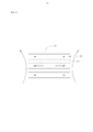
- Figure 4 is a schematic view showing the flow direction of the cross section of the cell in the battery of Figure 1.
- Figure 5 is a schematic illustration of the application of the battery of Figure 1 to an unmanned aerial vehicle.
- Figure 6 is a schematic view showing the flow direction of the cross section of the battery core in the unmanned aerial vehicle shown in Figure 4.
- a preferred embodiment of the present invention provides a battery 100 including a housing 11 and a plurality of cells 13 .
- the housing 11 is provided with a receiving cavity 111 for receiving the plurality of cells 13 .
- the housing 11 is a cylindrical structure with open ends, and includes a first housing 113 and a second housing 115.
- the first housing 113 is a U-shaped structure including a bottom plate 116 and two side plates 117 extending perpendicularly from opposite ends of the bottom plate 116 toward the same side of the bottom plate 116.
- the second housing 115 is fastened to the first housing 113 to enclose the receiving cavity 111 together with the first housing 113.
- the second housing 115 is a U-shaped structure including a bottom portion 118 and two side portions 119 extending perpendicularly from opposite ends of the bottom portion 118 toward the same side of the bottom portion 118, respectively.
- the side portions 119 are respectively fastened to the corresponding side plates 117, and the bottom portion 118 is disposed opposite to the bottom plate 116 to constitute the receiving cavity 111.
- the plurality of cells 13 are received in the accommodating cavity 111 and arranged in a stacked arrangement.
- the plurality of cells 13 are spaced apart from each other to form a plurality of air channels 131.
- each of the plurality of cells 13 is provided with at least one spacer 133 at both ends thereof, so that the plurality of cells 13 are spaced apart to form the plurality of air channels 131.
- the spacer 133 may be an insulator such as a foam.
- the spacer 133 may also be another thermal conductor such as a thermal pad.
- the housing 11 is further provided with a wind guiding hole 112.
- the number of the air guiding holes 112 is plural. Specifically, a part of the air guiding holes 112 are respectively disposed on the side plate 117 and have a long groove shape parallel to the bottom plate 116 as an air outlet hole.
- the opening of the casing 11 near the bottom of the battery core 13 forms a wind guiding hole and serves as an air inlet hole.
- the air outlet hole and the air inlet hole are both connected to the air passage 131, so that the airflow outside the casing 11 can enter the accommodating cavity 111 through the air inlet hole to form air convection and blow to the air.
- a plurality of cells 13 are described and flow through the air passages 131 and finally flow out of the air outlet holes to take away hot air between the plurality of battery cells 13.
- At least two of the plurality of air guiding holes 112 are respectively an air inlet hole and an air outlet hole, for example, a wind guiding hole disposed on the side plate 117 on the right side of the bottom plate 116 in FIG. 1 .
- 112 is an air inlet hole
- the air guiding hole 112 disposed on the side plate 117 on the left side of the bottom plate 116 in FIG. 1 is an air outlet hole.
- the air guiding hole 112 (ie, the air outlet hole) on the side plate 117 on the left side of the bottom plate 116 flows out.
- At least one inner wall of the housing 11 is in direct or indirect surface contact with the plurality of cells 13 to conduct heat generated by the plurality of cells 13 . Therefore, when the airflow outside the casing 11 enters the casing 11 from the air inlet hole and passes through the air passage 131, when the air outlet hole flows out, the casing 11 is outside. The air flow may also carry away heat transferred by the plurality of cells 13 to the housing 11 by heat.
- the shape of the air guiding hole 112 is not limited to the long groove shape described above, and may also be a dense circular hole shape or other shapes, and only the air guiding hole 112 and the plurality of airs need to be ensured.
- the passages 131 are in communication, and the airflow outside the casing 11 can enter the interior of the casing 11 through a portion of the air guiding holes 112, and then flow out from the other portion of the air guiding holes 112, that is, air convection is generated.
- the material of the casing 11 can be made of a material having better thermal conductivity.
- the material of the casing 11 may be aluminum, aluminum alloy, copper, copper alloy, silver, silver alloy, graphene, carbon nanotube.
- the thickness of the plate body of the housing 11 can be designed according to actual needs.
- the thickness of the plate body of the housing 11 can be 0.05-5 mm, for example, 0.05 mm, 0.15 mm, 0.25 mm, 0.35 mm. , 0.45 mm, 0.55 mm, 0.65 mm, 0.70 mm, 0.75 mm, 0.85 mm, 0.95 mm, 1.05 mm, 1.55 mm, 2.05 mm, 2.55 mm, 3.05 mm, 3.55 mm, 4.05 mm, 4.55 mm, 5.0 mm.
- the shape of the housing 11 is not limited to the above-described tubular structure with open ends, and the specific structure thereof can also be designed according to different requirements.
- the housing 11 is a box structure with an open end or a closed box structure or the like.
- the air inlet hole and the air outlet hole are not limited to be disposed on opposite sides of the housing 11 , and may be disposed on adjacent sides of the housing 11 .
- the battery 100 may further include at least one heat conducting frame 15 , and the at least one heat conducting frame 15 is installed in the receiving cavity 111 .
- the heat conducting frame 15 is thermally connected to the inner wall of the receiving cavity 111 of the housing 11 , and the heat conducting frame 15 can be in contact with the battery core 13 so that the heat of the battery core 13 can pass through the heat conducting frame 15 more quickly. Conducted to the housing 11 to better reduce the temperature rise.
- the heat conducting frame 15 includes a main body 151 for surface contact with the battery core 13 and two abutting perpendicularly extending from opposite ends of the main body 151 toward the same side of the main body 151. Board 153. Further, the size of the main body 151 is equivalent to the corresponding size of the battery core 13 such that the main body 151 is in surface contact with the battery core 13. Since the main body 151 is in surface contact with the battery core 13, the contact area of the battery core 13 and the heat conducting frame 15 can be effectively increased, thereby further improving the heat dissipation efficiency of the battery 100.
- the manner in which the heat conducting frame 15 is in contact with the housing 11 can be in different manners, for example, multi-point contact, line contact, and surface contact.
- the joints of the heat conducting frame 15 and the inner wall of the housing cavity 111 of the housing 11 are respectively provided with abutting faces to make surface contact between the heat conducting frame 15 and the inner wall of the receiving cavity 111.
- the abutting surface of the heat conducting frame 15 is disposed on the abutting plate 153 of the heat conducting frame 15
- the abutting surface of the housing 11 is disposed on the side plate 117 of the housing 11 .
- the height of the abutting plate 153 is equal to or lower than the height of the battery core 13.
- the spacer 133 is disposed between the main body board 151 and the adjacent battery cells 13 . As such, it is ensured that the air passage 131 can be formed between adjacent ones of the plurality of cells 13.
- the battery 100 further includes a housing 17.
- the outer casing 17 includes a first outer casing 171 and a second outer casing 173.
- the first outer casing 171 and the second outer casing 173 are fastened together and sleeved outside the casing 11 to protect the casing 11 .
- the outer casing 17 is also provided with at least a partial heat dissipation window 175 exposing the casing 11.
- the battery 100 further includes a web 18.
- One end of the plurality of cells 13 may be fixed to the connecting plate 18 and electrically connected to the connecting plate 18 to be fixed in the receiving cavity 111 of the casing 11 through the connecting plate 18.
- the connecting plate 18 can be a polar plate or a control circuit board.
- the connecting plate 18 may be disposed at the top of the housing 11.
- the air inlet holes may be disposed at the bottom of the housing 111, and the number of the air outlet holes is at least two, which are respectively located at two opposite sides of the housing 11. The two sides are located between the top of the housing 11 and the bottom.
- the connecting plate 18 flows out through the air outlet holes on both sides of the casing 11 to form air convection, thereby performing good heat dissipation on the connecting plate 18.
- the heat generated by each of the cells 13 will be radiated into the surrounding air by the heat radiation, wherein the air passages 131 between the plurality of cells 13 are concentrated. Heat.
- the portion of the plurality of cells 13 that is in contact with the housing 11 conducts heat to the housing 11 by heat conduction.
- airflow outside the casing 11 can pass through the air passages 131 through a portion of the air passages 112 in the casing 11 and be led out from the other air guiding holes 112, thereby taking away heat.
- the airflow outside the casing 11 can also carry away heat through the surface of the casing 11 of the battery 100, thereby accelerating the temperature drop of the battery 100 and achieving uniform temperature of the different cells 13.
- an embodiment of the present invention further provides an unmanned aerial vehicle 200 including at least a fuselage 201, a propeller 202, and the battery 100.
- a battery compartment 203 is disposed on the body 201.
- the battery 100 is disposed in the battery compartment 203.
- An external wind source may generate air convection to blow through the plurality of air guiding holes 112 to the plurality of cells 13 in the battery compartment 203 and through the air passage 131 between the plurality of cells 13 and The other portion of the air guiding holes 112 flows out to take away heat, and the air current generated by the wind source also carries heat away from the surface of the casing 11.
- the body 201 includes a body 2011 and a hollow arm 2013.
- the arm 2013 is fixedly connected to the body 2011 and is used to carry the propeller 202.
- the battery compartment 203 is disposed in the body 2011 of the body 201.
- the inner cavity of the arm 2013 communicates with the inner cavity of the battery compartment 203.
- an air inlet 205 and an air outlet 207 are further disposed on the body 201 of the UAV 200.
- the air inlet 205 is disposed on the body 2011, and the air outlet 207 is disposed on the arm 2013.
- the air inlet 205 and the air outlet 207 are both connected to the inner cavity of the battery compartment 203 for enabling convection of air inside and outside the battery compartment 203, wherein the air inlet 205 is used for inhaling the outside wind.
- the source generates a gas stream, and the gas stream can flow out of the air outlet 207 through the battery compartment 203.
- the air source of air convection may be directly from the propeller 202, and the airflow generated by the propeller 202 is introduced into the surface of the battery 100 through the air duct. Specifically, the airflow generated by the propeller 202 is introduced into the interior of the battery 100 through the air inlet 205, and flows out through the air outlet 207.
- the air convection air source may be from a separately installed fan (not shown) installed in the body 2011 of the UAV 200 or the battery 100. on. Referring to FIG. 6 together, when the air source of the air convection comes from a separately installed fan, the fan can be used to specifically provide convection power to the battery 100, thereby improving the heat dissipation effect.
- the battery 100 and the unmanned aerial vehicle 200 having the battery 100 are provided with a casing 11, and the casing 11 is provided with a corresponding air guiding hole 112.
- the air guiding hole 112 communicates with the air passage 131 between the plurality of batteries 13 to form air convection, so that the external airflow can enter the housing 11 through the partial air guiding hole 112, and blows toward The plurality of cells 13 then flow through the plurality of air passages 131 to flow out from the other portion of the air guiding holes 112 to remove hot air between the plurality of cells 13.
- the plurality of cells 13 are further in thermal contact with the housing 11 to conduct heat generated by the battery core 13 to the housing 11, thereby effectively reducing the temperature rise of the battery 100, and the heat dissipation effect thereof is better. It is good and can effectively improve the service life of the battery 100.
- the battery 100 described above does not need to be equipped with a power system, thereby avoiding an increase in additional power consumption, and the battery 100 and the unmanned aerial vehicle 200 having the battery 100 are small in size, light in weight, and low in cost.
Landscapes
- Chemical & Material Sciences (AREA)
- Chemical Kinetics & Catalysis (AREA)
- Electrochemistry (AREA)
- General Chemical & Material Sciences (AREA)
- Engineering & Computer Science (AREA)
- Aviation & Aerospace Engineering (AREA)
- Mechanical Engineering (AREA)
- Manufacturing & Machinery (AREA)
- Inorganic Chemistry (AREA)
- Remote Sensing (AREA)
- Battery Mounting, Suspending (AREA)
- Secondary Cells (AREA)
Abstract
一种电池(100),包括壳体(11),所述壳体(11)设置有容纳腔(111);以及多个电芯(13),所述多个电芯(13)收容于所述容纳腔(111)内,且层叠排布设置;其中,所述多个电芯(13)之间均间隔设置,进而形成多个空气通道(131);所述壳体(11)的侧面还设置有导风孔(112),所述导风孔(112)与所述空气通道(131)相连通,用以使得所述壳体(11)外的气流能够通过其中一部分所述导风孔(112)进入所述容纳腔(111),以吹向所述多个电芯(13),并流经所述空气通道(131),从另外一部分所述导风孔(112)流出,从而带走所述多个电芯(13)产生的热量。该电池(100)可以用于无人飞行器(200)。
Description
本发明涉及一种储能装置,尤其涉及一种电池及具有该电池的无人飞行器。
通常无人飞行器采用电池提供能量来源,以保证无人飞行器正常运转。该无人飞行器的动力电池使用时,其高倍率放电,产生热量大,导致温升问题严重。此外,无人飞行器的动力电池往往为多电芯串并联,电池内部热量不易散出,内部温度不均、局部温升过高,从而进一步加速电池衰减,缩短电池寿命,并影响安全性能。
目前,针对该多串并锂离子电池组的散热方式为加装导热架和导热外壳,以通过热传导的方式将电池内部热量传导至外部环境,或者通过主动散热方法在电池组加装风冷、水冷等主动冷却系统。然而,加装导热架和导热外壳的散热方式通过单一热传导对电芯与导热材料的接触面要求高,且传导效率有限。而风冷、水冷等主动冷却系统则需要额外加装元器件,增加能耗和重量,不利于无人飞行器的续航能力。
鉴于以上内容,有必要提供一种散热性能较佳的电池及具有该电池的无人飞行器。
一种电池,包括:
壳体,所述壳体设置有容纳腔;以及
多个电芯,所述多个电芯收容于所述容纳腔内,且层叠排布设置;
其中,所述多个电芯之间均间隔设置,进而形成多个空气通道;所述壳体的表面还设置有导风孔,所述导风孔与所述空气通道相连通,用以使得所述壳体外的气流能够通过其中一部分所述导风孔进入所述容纳腔,以吹向所述多个电芯,并流经所述空气通道,从另外一部分所述导风孔流出,从而带走所述多个电芯产生的热量。
进一步地,所述导风孔为多个,其中至少两个分别为进风孔及出风孔,所述壳体外的气流从所述进风孔进入到所述壳体内,经过所述空气通道后,从所述出风孔流出。
进一步地,所述导风孔为多个,其中至少两个分别为进风孔及出风孔,所述壳体外的气流从所述进风孔进入到所述壳体内,经过所述空气通道后,从所述出风孔流出。
进一步地,所述进风孔及所述出风孔分别位于所述壳体的相对两侧;
或者,所述进风孔及所述出风孔分别位于所述壳体的相邻两侧。
进一步地,所述壳体为两端开口的筒体结构;
或者,所述导热壳为具有一个开口或封闭的盒体结构。
进一步地,所述壳体包括第一壳体及第二壳体,所述第一壳体为U型结构,包括底板以及分别从所述底板的相对两端朝向底板的同一侧垂直延伸的两个侧板,所述第二壳体扣合在所述第一壳体上,以与所述第一壳体共同围成所述容纳腔。
进一步地,所述导风孔设置于所述第一壳体上,所述第二壳体与所述电芯直接或间接面接触。
进一步地,所述第二壳体为U型结构,包括底部以及分别从所述底部的相对两端朝向底部的同一侧垂直延伸的两个侧部,所述第二壳体扣合在所述第一壳体上,所述底部与所述电芯面接触,所述两个侧部上设置有所述导风孔。
进一步地,所述导风孔为密布的圆孔状;
或者,所述导风孔布设于所述侧板,且为与所述底板相互平行设置的长槽状。
进一步地,所述壳体为铝壳体或铝合金壳体;
或/及,所述壳体的至少一个内壁与所述多个电芯直接或间接面接触,以传导所述多个电芯产生的热量。
进一步地,所述壳体的厚度为0.05-5毫米。
进一步地,所述多个电芯中的每个电芯的两端均设置有至少一间隔部,进而使得所述多个电芯间隔设置,以形成所述多个空气通道。
进一步地,所述间隔部为绝缘体或导热体。
进一步地,所述电池还包括至少一个导热架,所述导热架安装于所述容纳腔内,所述电芯分别装设于相应的导热架内,所述导热架与所述容纳腔的内壁导热连接,使得所述导热架将所述多个电芯的热量传导至所述壳体上。
进一步地,所述导热架包括用于与所述电芯面接触的主体板以及分别从所述主体板的相对两端朝向所述主体板的同一侧垂直延伸的两个抵接板,所述抵接板与所述壳体的内壁面接触。
进一步地,所述抵接板的高度与所述电芯的高度相当或低于所述电芯的高度,所述间隔部设置于所述主体板与相邻的电芯之间。
进一步地,所述电池还包括外壳,所述壳体为导热壳,所述外壳套在所述壳体外,并且所述外壳开设有外露所述壳体的至少局部的散热窗口。
一种无人飞行器,包括:
设有电池仓的机身;以及
上述各项的电池,所述电池设置于所述电池仓内,风源产生空气对流,以通过其中一部分所述导风孔吹向所述多个电芯,并穿过所述多个电芯之间的空气通道,从而带走热量,同时所述风源产生的气流还通过所述壳体的表面带走热量。
进一步地,所述空气对流的风源来自于所述无人飞行器的螺旋桨,所述螺旋桨产生的气流通过风道导入至电池表面;
或者,所述空气对流的风源来自于独立安装的风扇,用于对所述电池散热。
进一步地,所述机身还包括进风口以及出风口,所述进风口以及所述出风口均与所述电池仓连通;其中,所述进风口用于吸入所述螺旋桨产生的气流,并且所述气流能够经所述电池仓后从所述出风口流出。
进一步地,所述机身包括机体以及中空的机臂,所述机臂与所述机体固定连接,所述机臂用于承载所述螺旋桨,其中,所述电池仓设置于所述机体内并且与所述机臂连通,所述进风口设于所述机体上,所述出风口设置于所述机臂上。
进一步地,所述机身包括机体以及机臂,所述机臂与所述机体固定连接,所述机臂用于承载所述螺旋桨,其中,所述电池仓设置于所述机体内,所述独立的风扇安装于所述机体内或所述电池上。
本发明中的电池及具有该电池的无人飞行器设置有壳体,该壳体上设置有相应的导风孔。该导风孔与所述多个电芯之间的空气通道相连通,进而形成空气对流,以使得外界的气流可通过部分导风孔进入所述壳体内,并吹向所述多个电芯,再流经所述多个空气通道,进而从另外一部分导风孔流出,以带走所述多个电芯之间的热空气,从而有效降低电池温升,其散热效果较佳,且可有效提高该电池的使用寿命。
图1为本发明实施例的电池的分解示意图。
图2为图1所示电池中II处的放大示意图。
图3为图1所示电池的导热架的示意图。
图4为图1所示电池中电芯横截面的气流走向示意图。
图5为图1所述电池应用至无人飞行器的示意图。
图6为图4所示无人飞行器中电芯横截面的气流走向示意图。
| 电池 | 100 |
| 壳体 | 11 |
| 容纳腔 | 111 |
| 导风孔 | 112 |
| 第一壳体 | 113 |
| 第二壳体 | 115 |
| 底板 | 116 |
| 侧板 | 117 |
| 底部 | 118 |
| 侧部 | 119 |
| 电芯 | 13 |
| 空气通道 | 131 |
| 间隔部 | 133 |
| 导热架 | 15 |
| 主板体 | 151 |
| 抵接板 | 153 |
| 外壳 | 17 |
| 第一外壳 | 171 |
| 第二外壳 | 173 |
| 散热窗口 | 175 |
| 连接板 | 18 |
| 无人飞行器 | 200 |
| 机身 | 201 |
| 机体 | 2011 |
| 机臂 | 2013 |
| 螺旋桨 | 202 |
| 电池仓 | 203 |
| 进风口 | 205 |
| 出风口 | 207 |
如下具体实施方式将结合上述附图进一步说明本发明。
下面将结合本发明实施例中的附图,对本发明实施例中的技术方案进行清楚、完整地描述,显然,所描述的实施例仅仅是本发明一部分实施例,而不是全部的实施例。基于本发明中的实施例,本领域普通技术人员在没有做出创造性劳动前提下所获得的所有其他实施例,都属于本发明保护的范围。
需要说明的是,当组件被称为“固定于”另一个组件,它可以直接在另一个组件上或者也可以存在居中的组件。当一个组件被认为是“连接”另一个组件,它可以是直接连接到另一个组件或者可能同时存在居中组件。本文所使用的术语“垂直的”、“水平的”、“左”、“右”以及类似的表述只是为了说明的目的。
除非另有定义,本文所使用的所有的技术和科学术语与属于本发明的技术领域的技术人员通常理解的含义相同。本文中在本发明的说明书中所使用的术语只是为了描述具体的实施例的目的,不是旨在于限制本发明。本文所使用的术语“及/或”包括一个或多个相关的所列项目的任意的和所有的组合。
下面结合附图,对本发明的一些实施方式作详细说明。在不冲突的情况下,下述的实施例及实施例中的特征可以相互组合。
请参阅图1,本发明较佳实施方式提供一种电池100,包括壳体11及多个电芯13。所述壳体11设置有容纳腔111,用以收容所述多个电芯13。
在本实施例中,所述壳体11为两端开口的筒体结构,其包括第一壳体113及第二壳体115。所述第一壳体113为U型结构,包括底板116以及分别从所述底板116的相对两端朝向底板116的同一侧垂直延伸的两个侧板117。所述第二壳体115扣合在所述第一壳体113上,以与所述第一壳体113共同围成所述容纳腔111。具体的,所述第二壳体115为U型结构,包括底部118以及分别从所述底部118的相对两端朝向底部118的同一侧垂直延伸的两个侧部119。其中所述侧部119分别扣合于相应的侧板117上,所述底部118与所述底板116相对设置,进而构成所述容纳腔111。
请一并参阅图2,所述多个电芯13收容于所述容纳腔111内,且层叠排布设置。所述多个电芯13之间均间隔设置,进而形成多个空气通道131。可以理解,所述多个电芯13中的每个电芯13的两端均设置有至少一间隔部133,进而使得所述多个电芯13间隔设置,以形成所述多个空气通道131。在本实施例中,所述间隔部133可以为绝缘体,例如泡棉。当然,在其他实施例中,所述间隔部133还可以为导热垫片等其他导热体。
所述壳体11上还设置有导风孔112。在本实施例中,所述导风孔112的数量为多个。具体的,其中一部分所述导风孔112分别布设于所述侧板117,且呈与所述底板116相互平行设置的长槽状,作为出风孔。所述壳体11靠近所述电芯13的底部的开口形成一导风孔,并且作为进风孔。所述出风孔及进风孔均与所述空气通道131相连通,用以使得所述壳体11外的气流能够通过进风孔进入所述容纳腔111,以形成空气对流而吹向所述多个电芯13,并流经所述空气通道131,最后从出风孔流出,从而带走所述多个电芯13之间的热空气。
在其他实施中,所述多个导风孔112中的至少两个分别为进风孔及出风孔,例如,设置于图1中所述底板116右侧的侧板117上的导风孔112为进风孔,设置于图1中所述底板116左侧的侧板117上的导风孔112为出风孔。如此,所述壳体11外的气流可从所述底板116右侧的侧板117上的导风孔112(即进风孔)进入到所述壳体11内,经过所述空气通道131后,从所述底板116左侧的侧板117上的导风孔112(即出风孔)流出。
可以理解,在其他实施例中,所述壳体11的至少一个内壁与所述多个电芯13直接或间接面接触,以传导所述多个电芯13产生的热量。因此,当所述壳体11外的气流从所述进风孔进入到所述壳体11内,并经过所述空气通道131后,从所述出风孔流出时,所述壳体11外的气流还可带走所述多个电芯13通过热传导至所述壳体11上的热量。
可以理解,所述导风孔112的形状不局限于上述所述的长槽状,其还可以为密布的圆孔状或其他形状,仅需确保所述导风孔112与所述多个空气通道131相连通,并使得所述壳体11外的气流可通过一部分导风孔112进入壳体11内部,再从另外一部分导风孔112流出,即产生空气对流。
可以理解,所述壳体11的材料可以采用导热性较好的材料制成。例如,壳体11的材料可以为铝,铝合金,铜,铜合金,银,银合金,石墨烯,碳纳米管。
所述壳体11的板体的厚度可以根据实际需求来设计,优选地,所述壳体11的板体的厚度可以为0.05-5毫米,例如,0.05毫米,0.15毫米,0.25毫米,0.35毫米,0.45毫米,0.55毫米,0.65毫米,0.70毫米,0.75毫米,0.85毫米,0.95毫米,1.05毫米,1.55毫米,2.05毫米,2.55毫米,3.05毫米,3.55毫米,4.05毫米,4.55毫米,5.0毫米。
可以理解,在其他实施例中,所述壳体11的形状不局限于上述所述的两端开口的筒体结构,其具体结构还可以根据不同需求来设计。例如,所述壳体11为一端开口的盒体结构或者封闭的盒体结构等等。如此,所述进风孔及所述出风孔不局限于设置于所述壳体11的相对两侧,其还可设置于所述壳体11的相邻两侧。
请一并参阅图3,可以理解,在其他实施例中,所述电池100还可包括至少一个导热架15,所述至少一个导热架15安装在所述容纳腔111内。其中,所述导热架15与壳体11的容纳腔111的内壁导热连接,并且导热架15能够与电芯13接触,以使得所述电芯13的热量可更快地通过所述导热架15传导至壳体11上,进而更好的降低温升。
在本实施例中,所述导热架15包括用于与电芯13面接触的主板体151及分别从所述主板体151的相对两端朝向主板体151的同一侧垂直延伸的两个抵接板153。进一步的,所述主板体151的尺寸与电芯13对应的尺寸相当,以使得所述主板体151与电芯13面接触。由于主板体151与所述电芯13面接触,如此可有效增大所述电芯13与导热架15的接触面积,从而进一步提高该电池100的散热效率。
可以理解,所述导热架15与所述壳体11的接触方式可以采用不同方式,例如,多点接触,线接触,面接触。在本实施例中,导热架15与壳体11的容纳腔111的内壁的连接处分别设有抵接面,以使导热架15与收纳腔111的内壁的连接处形成面接触。具体地,所述导热架15的抵接面设于导热架15的抵接板153上,所述壳体11的抵接面设于所述壳体11的侧板117上。
可以理解,当所述电池100设置所述导热架15时,所述抵接板153的高度与所述电芯13的高度相当或低于所述电芯13的高度。所述间隔部133设置于所述主体板151与相邻的电芯13之间。如此,以确保所述多个电芯13中相邻的电芯13之间可形成所述空气通道131。
可以理解,请再次参阅图1,在其他实施例中,所述电池100还包括外壳17。所述外壳17包括第一外壳171及第二外壳173。所述第一外壳171与第二外壳173相互扣合在一起,并共同套设在所述壳体11外,以保护所述壳体11。另外,所述外壳17还开设有外露所述壳体11的至少局部的散热窗口175。
可以理解,在其他实施例中,所述电池100还包括连接板18。所述多个电芯13的一端可固定于所述连接板18上,且与所述连接板18电连接,以通过所述连接板18固定于所述壳体11的容纳腔111内。所述连接板18可以为极耳板或控制电路板。所述连接板18可设置于所述壳体11的顶部。对应的,所述进风孔可设置于所述壳体111的底部,且所述出风孔的数量为至少两个,其分别位于所述壳体11的两个相对侧面。所述两个侧面位于所述壳体11的顶部与所述底部之间。如此,当壳体11外的气流通过所述壳体11的底部处的进风孔进入所述壳体11内时,可吹向所述多个电芯13以及位于所述壳体11顶部的连接板18,再通过位于所述壳体11两侧的出风孔流出,以形成空气对流,进而对所述连接板18进行良好散热。
请一并参阅图4,使用该电池100时,每一个电芯13产生的热量将通过热辐射作用辐射至周围的空气中,其中所述多个电芯13之间的空气通道131聚集大量的热量。同时,所述多个电芯13与壳体11接触的部分通过热传导作用将热量传导至壳体11上。如此,壳体11外部的气流可通过壳体11上的部分导风孔112穿过所述空气通道131,并从另外的导风孔112导出,从而带走热量。同时,所述壳体11外部的气流也可通过电池100的壳体11表面带走热量,从而加速电池100的降温,并实现不同电芯13的温度一致。
请参阅图5,本发明的实施方式还提供一种无人飞行器200,该无人飞行器200至少包括机身201、螺旋桨202以及所述电池100。所述机身201上设有电池仓203。所述电池100设于电池仓203内。外界的风源可产生空气对流,以通过其中一部分导风孔112吹向电池仓203内的所述多个电芯13,并穿过所述多个电芯13之间的空气通道131,并从另外一部分导风孔112流出,从而带走热量,同时所述风源产生的气流还通过所述壳体11的表面带走热量。
具体地,所述机身201包括机体2011以及中空的机臂2013。所述机臂2013与所述机体2011固定连接,且用以承载所述螺旋桨202。所述电池仓203设于所述机身201的机体2011内。所述机臂2013的内腔与电池仓203的内腔相连通。进一步地,所述无人飞行器200的机身201上还开设有进风口205及出风口207。所述进风口205设于所述机体2011上,所述出风口207设置于所述机臂2013上。所述进风口205与所述出风口207均与所述电池仓203的内腔相连通,其用于使电池仓203内外的空气能够形成对流,其中所述进风口205用于吸入外界的风源产生的气流,并且所述气流能够经所述电池仓203后从所述出风口207流出。
可以理解,在其中一个实施例中,所述空气对流的风源可直接来自于所述螺旋桨202,所述螺旋桨202产生的气流通过风道导入至所述电池100表面。具体的,所述螺旋桨202产生的气流通过所述进风口205导入所述电池100内部,并通过所述出风口207流出。
可以理解,在另外的实施例中,所述空气对流的风源可来自于独立安装的风扇(图未示),所述独立的风扇安装于所述无人飞行器200的机体2011内或电池100上。请一并参阅图6,当所述空气对流的风源来自于独立安装的风扇时,该风扇可用于专门对电池100提供对流电源,进而提高散热效果。
上述电池100及具有该电池100的无人飞行器200设置有壳体11,该壳体11上设置有相应的导风孔112。该导风孔112与所述多个电芯13之间的空气通道131相连通,进而形成空气对流,以使得外界的气流可通过部分导风孔112进入所述壳体11内,并吹向所述多个电芯13,再流经所述多个空气通道131,进而从另外一部分导风孔112流出,以带走所述多个电芯13之间的热空气。另外,所述多个电芯13还与所述壳体11进行导热接触,进而将所述电芯13产生的热量传导至所述壳体11,从而有效降低电池100温升,其散热效果较佳,且可有效提高该电池100的使用寿命。上述电池100无需配备动力系统,从而避免增加额外的功耗,并且使得上述电池100及具有该电池100的无人飞行器200体积较小,重量较轻,成本较低。
以上实施方式仅用以说明本发明的技术方案而非限制,尽管参照以上较佳实施方式对本发明进行了详细说明,本领域的普通技术人员应当理解,可以对本发明的技术方案进行修改或等同替换都不应脱离本发明技术方案的精神和范围。本领域技术人员还可在本发明精神内做其它变化等用在本发明的设计,只要其不偏离本发明的技术效果均可。这些依据本发明精神所做的变化,都应包含在本发明所要求保护的范围之内。
Claims (21)
- 一种电池,其特征在于:所述电池包括:壳体,所述壳体设置有容纳腔;以及多个电芯,所述多个电芯收容于所述容纳腔内,且层叠排布设置;其中,所述多个电芯之间均间隔设置,进而形成多个空气通道;所述壳体的表面还设置有导风孔,所述导风孔与所述空气通道相连通,用以使得所述壳体外的气流能够通过其中一部分所述导风孔进入所述容纳腔,以吹向所述多个电芯,并流经所述空气通道,从另外一部分所述导风孔流出,从而带走所述多个电芯产生的热量。
- 如权利要求1所述的电池,其特征在于:所述导风孔为多个,其中至少两个分别为进风孔及出风孔,所述壳体外的气流从所述进风孔进入到所述壳体内,经过所述空气通道后,从所述出风孔流出。
- 如权利要求2所述的电池,其特征在于:所述进风孔及所述出风孔分别位于所述壳体的相对两侧;或者,所述进风孔及所述出风孔分别位于所述壳体的相邻两侧。
- 如权利要求3所述的电池,其特征在于:所述壳体为两端开口的筒体结构;或者,所述导热壳为具有一个开口或封闭的盒体结构。
- 如权利要求1所述的电池,其特征在于:所述壳体包括第一壳体及第二壳体,所述第一壳体为U型结构,包括底板以及分别从所述底板的相对两端朝向底板的同一侧垂直延伸的两个侧板,所述第二壳体扣合在所述第一壳体上,以与所述第一壳体共同围成所述容纳腔。
- 如权利要求5所述的电池,其特征在于:所述导风孔设置于所述第一壳体上,所述第二壳体与所述电芯直接或间接面接触。
- 如权利要求5或6所述的电池,其特征在于:所述第二壳体为U型结构,包括底部以及分别从所述底部的相对两端朝向底部的同一侧垂直延伸的两个侧部,所述第二壳体扣合在所述第一壳体上,所述底部与所述电芯面接触,所述两个侧部上设置有所述导风孔。
- 如权利要求5所述的电池,其特征在于:所述导风孔为密布的圆孔状;或者,所述导风孔布设于所述侧板,且为与所述底板相互平行设置的长槽状。
- 如权利要求1所述的电池,其特征在于:所述壳体为铝壳体或铝合金壳体;或/及,所述壳体的至少一个内壁与所述多个电芯直接或间接面接触,以传导所述多个电芯产生的热量。
- 如权利要求1所述的电池,其特征在于:所述壳体的厚度为0.05-5毫米。
- 如权利要求1所述的电池,其特征在于:所述多个电芯中的每个电芯的两端均设置有至少一间隔部,进而使得所述多个电芯间隔设置,以形成所述多个空气通道。
- 如权利要求11所述的电池,其特征在于:所述间隔部为绝缘体或导热体。
- 如权利要求11所述的电池,其特征在于:所述电池还包括至少一个导热架,所述导热架安装于所述容纳腔内,所述电芯分别装设于相应的导热架内,所述导热架与所述容纳腔的内壁导热连接,使得所述导热架将所述多个电芯的热量传导至所述壳体上。
- 如权利要求13所述的电池,其特征在于:所述导热架包括用于与所述电芯面接触的主体板以及分别从所述主体板的相对两端朝向所述主体板的同一侧垂直延伸的两个抵接板,所述抵接板与所述壳体的内壁面接触。
- 如权利要求14所述的电池,其特征在于:所述抵接板的高度与所述电芯的高度相当或低于所述电芯的高度,所述间隔部设置于所述主体板与相邻的电芯之间。
- 如权利要求1所述的电池,其特征在于:所述电池还包括外壳,所述壳体为导热壳,所述外壳套在所述壳体外,并且所述外壳开设有外露所述壳体的至少局部的散热窗口。
- 一种无人飞行器,其特征在于,包括:设有电池仓的机身;以及权利要求1-16项中任一项所述的电池,所述电池设置于所述电池仓内,风源产生空气对流,以通过其中一部分所述导风孔吹向所述多个电芯,并穿过所述多个电芯之间的空气通道,从而带走热量,同时所述风源产生的气流还通过所述壳体的表面带走热量。
- 如权利要求17所述的无人飞行器,其特征在于:所述空气对流的风源来自于所述无人飞行器的螺旋桨,所述螺旋桨产生的气流通过风道导入至电池表面;或者,所述空气对流的风源来自于独立安装的风扇,用于对所述电池散热。
- 如权利要求18所述的无人飞行器,其特征在于:所述机身还包括进风口以及出风口,所述进风口以及所述出风口均与所述电池仓连通;其中,所述进风口用于吸入所述螺旋桨产生的气流,并且所述气流能够经所述电池仓后从所述出风口流出。
- 如权利要求19所述的无人飞行器,其特征在于:所述机身包括机体以及中空的机臂,所述机臂与所述机体固定连接,所述机臂用于承载所述螺旋桨,其中,所述电池仓设置于所述机体内并且与所述机臂连通,所述进风口设于所述机体上,所述出风口设置于所述机臂上。
- 如权利要求18所述的无人飞行器,其特征在于:所述机身包括机体以及机臂,所述机臂与所述机体固定连接,所述机臂用于承载所述螺旋桨,其中,所述电池仓设置于所述机体内,所述独立的风扇安装于所述机体内或所述电池上。
Priority Applications (3)
| Application Number | Priority Date | Filing Date | Title |
|---|---|---|---|
| CN202110070808.7A CN112909409A (zh) | 2015-12-25 | 2015-12-25 | 无人飞行器 |
| CN201580067014.8A CN107004919B (zh) | 2015-12-25 | 2015-12-25 | 电池及具有该电池的无人飞行器 |
| PCT/CN2015/098832 WO2017107170A1 (zh) | 2015-12-25 | 2015-12-25 | 电池及具有该电池的无人飞行器 |
Applications Claiming Priority (1)
| Application Number | Priority Date | Filing Date | Title |
|---|---|---|---|
| PCT/CN2015/098832 WO2017107170A1 (zh) | 2015-12-25 | 2015-12-25 | 电池及具有该电池的无人飞行器 |
Publications (1)
| Publication Number | Publication Date |
|---|---|
| WO2017107170A1 true WO2017107170A1 (zh) | 2017-06-29 |
Family
ID=59088880
Family Applications (1)
| Application Number | Title | Priority Date | Filing Date |
|---|---|---|---|
| PCT/CN2015/098832 Ceased WO2017107170A1 (zh) | 2015-12-25 | 2015-12-25 | 电池及具有该电池的无人飞行器 |
Country Status (2)
| Country | Link |
|---|---|
| CN (2) | CN107004919B (zh) |
| WO (1) | WO2017107170A1 (zh) |
Cited By (13)
| Publication number | Priority date | Publication date | Assignee | Title |
|---|---|---|---|---|
| CN108281590A (zh) * | 2018-03-29 | 2018-07-13 | 长沙优力电驱动系统有限公司 | 电池热管理装置及设有该装置的电池 |
| CN108601269A (zh) * | 2018-06-29 | 2018-09-28 | 四川斐讯信息技术有限公司 | 一种通讯设备及其中框散热结构 |
| CN110311189A (zh) * | 2019-08-12 | 2019-10-08 | 深圳市嘉名科技有限公司 | 电池模组、电池包、电动车及电网系统 |
| CN110571383A (zh) * | 2019-09-17 | 2019-12-13 | 英鸿纳米科技股份有限公司 | 一种大型飞行器专用纳米电容电池结构 |
| CN112455648A (zh) * | 2019-09-09 | 2021-03-09 | 苏州臻迪智能科技有限公司 | 一种无人机 |
| EP3883041A1 (en) * | 2020-03-17 | 2021-09-22 | Aurora Flight Sciences Corporation, a subsidiary of The Boeing Company | Battery cooling systems and methods |
| CN113438861A (zh) * | 2021-06-10 | 2021-09-24 | 徐州利明汽车电器有限公司 | 一种自换气散热型汽车调节器 |
| CN113571826A (zh) * | 2020-04-10 | 2021-10-29 | 北京昆兰新能源技术有限公司 | 一种合金塑料壳体的电池模组 |
| CN114212262A (zh) * | 2021-12-16 | 2022-03-22 | 上海沃兰特航空技术有限责任公司 | 电动垂直起降飞行器 |
| CN116031535A (zh) * | 2023-02-13 | 2023-04-28 | 南京莱迪新能源科技有限公司 | 一种梯次利用锂电池移动电源多维嵌入式散热组件及方法 |
| WO2023107193A1 (en) * | 2021-12-10 | 2023-06-15 | Wing Aviation Llc | Active thermal control of uav energy storage units |
| WO2024183482A1 (zh) * | 2023-03-06 | 2024-09-12 | 珠海冠宇电源有限公司 | 电池包 |
| CN119898499A (zh) * | 2025-04-02 | 2025-04-29 | 飞客工场科技(北京)有限公司 | 无人机机载电源模组及无人机 |
Families Citing this family (7)
| Publication number | Priority date | Publication date | Assignee | Title |
|---|---|---|---|---|
| CN110313226B (zh) * | 2018-08-16 | 2020-11-20 | 深圳市大疆创新科技有限公司 | 散热组件、散热模组和无人飞行器 |
| WO2020103061A1 (zh) * | 2018-11-21 | 2020-05-28 | 深圳市大疆创新科技有限公司 | 电池和具有该电池的无人机及电子设备 |
| CN109573063B (zh) * | 2018-12-28 | 2024-12-24 | 深圳市道通智能航空技术股份有限公司 | 一种飞行器 |
| CN111525210B (zh) * | 2020-04-27 | 2021-12-28 | 深圳市元鼎科技有限公司 | 户外电源 |
| WO2021217545A1 (zh) * | 2020-04-30 | 2021-11-04 | 深圳市大疆创新科技有限公司 | 无人飞行器 |
| CN111987382A (zh) * | 2020-08-18 | 2020-11-24 | 深圳市道通智能航空技术有限公司 | 一种无人机地面基站的电池散热组件及无人机地面基站 |
| CN114069126B (zh) * | 2021-11-22 | 2024-04-30 | 东莞新能安科技有限公司 | 电池包、电池包系统及用电设备 |
Citations (6)
| Publication number | Priority date | Publication date | Assignee | Title |
|---|---|---|---|---|
| CN203601572U (zh) * | 2013-11-07 | 2014-05-21 | 保利科技(珠海)有限公司 | 无人飞行器电池及具有该电池的飞行器 |
| CN104241715A (zh) * | 2014-08-18 | 2014-12-24 | 浙江超威创元实业有限公司 | 模块化电池 |
| CN204407397U (zh) * | 2014-11-14 | 2015-06-17 | 北京圣比和科技有限公司 | 一种散热式动力电池模块组装盒 |
| US20150166176A1 (en) * | 2011-10-18 | 2015-06-18 | The Boeing Company | Methods and systems for retrieving personnel |
| CN204642144U (zh) * | 2015-04-30 | 2015-09-16 | 深圳市大疆创新科技有限公司 | 无人机 |
| US20150259066A1 (en) * | 2012-10-19 | 2015-09-17 | Aeryon Labs Inc. | Hovering unmanned aerial vehicle |
Family Cites Families (8)
| Publication number | Priority date | Publication date | Assignee | Title |
|---|---|---|---|---|
| US5338624A (en) * | 1993-02-08 | 1994-08-16 | Globe-Union Inc. | Thermal management of rechargeable batteries |
| KR100860454B1 (ko) * | 2004-10-08 | 2008-09-25 | 주식회사 엘지화학 | 이차전지 모듈 |
| CN100495280C (zh) * | 2007-11-01 | 2009-06-03 | 上海交通大学 | 动力锂电池组温度控制装置 |
| CN101938019A (zh) * | 2010-09-13 | 2011-01-05 | 天津市捷威动力工业有限公司 | 动力电池组及其电池模块 |
| CN203423218U (zh) * | 2013-08-20 | 2014-02-05 | 华霆(常州)动力技术有限公司 | 一种密封散热电池箱 |
| CN203883057U (zh) * | 2014-04-08 | 2014-10-15 | 郑州宇通客车股份有限公司 | 电源箱及其箱体 |
| CN203850357U (zh) * | 2014-04-30 | 2014-09-24 | 中航锂电(洛阳)有限公司 | 储能电池组及使用该电池组的电池箱 |
| CN204179174U (zh) * | 2014-11-10 | 2015-02-25 | 深圳市大疆创新科技有限公司 | 电池及其热管理装置、以及具有该电池的uav |
-
2015
- 2015-12-25 CN CN201580067014.8A patent/CN107004919B/zh not_active Expired - Fee Related
- 2015-12-25 WO PCT/CN2015/098832 patent/WO2017107170A1/zh not_active Ceased
- 2015-12-25 CN CN202110070808.7A patent/CN112909409A/zh active Pending
Patent Citations (6)
| Publication number | Priority date | Publication date | Assignee | Title |
|---|---|---|---|---|
| US20150166176A1 (en) * | 2011-10-18 | 2015-06-18 | The Boeing Company | Methods and systems for retrieving personnel |
| US20150259066A1 (en) * | 2012-10-19 | 2015-09-17 | Aeryon Labs Inc. | Hovering unmanned aerial vehicle |
| CN203601572U (zh) * | 2013-11-07 | 2014-05-21 | 保利科技(珠海)有限公司 | 无人飞行器电池及具有该电池的飞行器 |
| CN104241715A (zh) * | 2014-08-18 | 2014-12-24 | 浙江超威创元实业有限公司 | 模块化电池 |
| CN204407397U (zh) * | 2014-11-14 | 2015-06-17 | 北京圣比和科技有限公司 | 一种散热式动力电池模块组装盒 |
| CN204642144U (zh) * | 2015-04-30 | 2015-09-16 | 深圳市大疆创新科技有限公司 | 无人机 |
Cited By (19)
| Publication number | Priority date | Publication date | Assignee | Title |
|---|---|---|---|---|
| CN108281590B (zh) * | 2018-03-29 | 2024-02-02 | 长沙优力电驱动系统有限公司 | 电池热管理装置及设有该装置的电池 |
| CN108281590A (zh) * | 2018-03-29 | 2018-07-13 | 长沙优力电驱动系统有限公司 | 电池热管理装置及设有该装置的电池 |
| CN108601269A (zh) * | 2018-06-29 | 2018-09-28 | 四川斐讯信息技术有限公司 | 一种通讯设备及其中框散热结构 |
| CN110311189A (zh) * | 2019-08-12 | 2019-10-08 | 深圳市嘉名科技有限公司 | 电池模组、电池包、电动车及电网系统 |
| CN112455648A (zh) * | 2019-09-09 | 2021-03-09 | 苏州臻迪智能科技有限公司 | 一种无人机 |
| CN110571383A (zh) * | 2019-09-17 | 2019-12-13 | 英鸿纳米科技股份有限公司 | 一种大型飞行器专用纳米电容电池结构 |
| US11646461B2 (en) | 2020-03-17 | 2023-05-09 | The Boeing Company | Battery cooling systems and methods |
| EP3883041A1 (en) * | 2020-03-17 | 2021-09-22 | Aurora Flight Sciences Corporation, a subsidiary of The Boeing Company | Battery cooling systems and methods |
| CN113571826A (zh) * | 2020-04-10 | 2021-10-29 | 北京昆兰新能源技术有限公司 | 一种合金塑料壳体的电池模组 |
| CN113571826B (zh) * | 2020-04-10 | 2023-05-30 | 北京昆兰新能源技术有限公司 | 一种合金塑料壳体的电池模组 |
| CN113438861A (zh) * | 2021-06-10 | 2021-09-24 | 徐州利明汽车电器有限公司 | 一种自换气散热型汽车调节器 |
| US12119472B2 (en) | 2021-12-10 | 2024-10-15 | Wing Aviation Llc | Active thermal control of UAV energy storage units |
| WO2023107193A1 (en) * | 2021-12-10 | 2023-06-15 | Wing Aviation Llc | Active thermal control of uav energy storage units |
| CN114212262A (zh) * | 2021-12-16 | 2022-03-22 | 上海沃兰特航空技术有限责任公司 | 电动垂直起降飞行器 |
| CN116031535B (zh) * | 2023-02-13 | 2023-06-02 | 南京莱迪新能源科技有限公司 | 一种梯次利用锂电池移动电源多维嵌入式散热组件及方法 |
| CN116031535A (zh) * | 2023-02-13 | 2023-04-28 | 南京莱迪新能源科技有限公司 | 一种梯次利用锂电池移动电源多维嵌入式散热组件及方法 |
| WO2024183482A1 (zh) * | 2023-03-06 | 2024-09-12 | 珠海冠宇电源有限公司 | 电池包 |
| CN119898499A (zh) * | 2025-04-02 | 2025-04-29 | 飞客工场科技(北京)有限公司 | 无人机机载电源模组及无人机 |
| CN119898499B (zh) * | 2025-04-02 | 2025-06-17 | 飞客工场科技(北京)有限公司 | 无人机机载电源模组及无人机 |
Also Published As
| Publication number | Publication date |
|---|---|
| CN107004919A (zh) | 2017-08-01 |
| CN112909409A (zh) | 2021-06-04 |
| CN107004919B (zh) | 2021-02-09 |
Similar Documents
| Publication | Publication Date | Title |
|---|---|---|
| WO2017107170A1 (zh) | 电池及具有该电池的无人飞行器 | |
| CN205488366U (zh) | 电池及具有该电池的无人飞行器 | |
| US10462938B2 (en) | Inverter power cabinet | |
| CN111883712B (zh) | 储能电池柜 | |
| WO2010071370A2 (en) | Battery module having cooling means, and middle or large-sized battery pack containing the same | |
| CN115413200A (zh) | 一种功率设备及光伏系统 | |
| WO2012023753A2 (ko) | 콤팩트한 구조와 우수한 방열 특성의 전지모듈 및 그것을 포함하는 중대형 전지팩 | |
| WO2020103061A1 (zh) | 电池和具有该电池的无人机及电子设备 | |
| CN219286513U (zh) | 风冷电池包 | |
| CN108520932A (zh) | 电池包及具有其的车辆 | |
| CN110581328B (zh) | 电池pack冷却组件、储能集装箱及冷却方法 | |
| CN106711541A (zh) | 一种电动方程式赛车的紧凑型强制风冷动力电池系统总成 | |
| CN115441093A (zh) | 一种电池模组和含该电池模组的飞行器 | |
| CN209822749U (zh) | 一种机车用风冷软包动力电池箱 | |
| CN206422181U (zh) | 一种电动方程式赛车的紧凑型强制风冷动力电池系统总成 | |
| CN216720054U (zh) | 一种电池包的风冷散热系统及电池包 | |
| CN207368167U (zh) | 一种电池包 | |
| WO2023123348A1 (zh) | 电池模组及电池包 | |
| CN111416175B (zh) | 电池模组 | |
| CN218039454U (zh) | 一种电池包及储能系统 | |
| CN202633409U (zh) | 一种软包装电池组 | |
| CN115084683A (zh) | 电池包及电源 | |
| CN102593550B (zh) | 一种软包装箱体电池 | |
| WO2019056415A1 (zh) | 冰箱 | |
| CN221960491U (zh) | 一种基于19英寸的加固vpx机箱 |
Legal Events
| Date | Code | Title | Description |
|---|---|---|---|
| 121 | Ep: the epo has been informed by wipo that ep was designated in this application |
Ref document number: 15911169 Country of ref document: EP Kind code of ref document: A1 |
|
| NENP | Non-entry into the national phase |
Ref country code: DE |
|
| 122 | Ep: pct application non-entry in european phase |
Ref document number: 15911169 Country of ref document: EP Kind code of ref document: A1 |