WO2017104560A1 - モータシャフト - Google Patents
モータシャフト Download PDFInfo
- Publication number
- WO2017104560A1 WO2017104560A1 PCT/JP2016/086690 JP2016086690W WO2017104560A1 WO 2017104560 A1 WO2017104560 A1 WO 2017104560A1 JP 2016086690 W JP2016086690 W JP 2016086690W WO 2017104560 A1 WO2017104560 A1 WO 2017104560A1
- Authority
- WO
- WIPO (PCT)
- Prior art keywords
- motor shaft
- support portions
- outer portion
- shaft according
- motor
- Prior art date
- Legal status (The legal status is an assumption and is not a legal conclusion. Google has not performed a legal analysis and makes no representation as to the accuracy of the status listed.)
- Ceased
Links
Images





Classifications
-
- F—MECHANICAL ENGINEERING; LIGHTING; HEATING; WEAPONS; BLASTING
- F16—ENGINEERING ELEMENTS AND UNITS; GENERAL MEASURES FOR PRODUCING AND MAINTAINING EFFECTIVE FUNCTIONING OF MACHINES OR INSTALLATIONS; THERMAL INSULATION IN GENERAL
- F16C—SHAFTS; FLEXIBLE SHAFTS; ELEMENTS OR CRANKSHAFT MECHANISMS; ROTARY BODIES OTHER THAN GEARING ELEMENTS; BEARINGS
- F16C3/00—Shafts; Axles; Cranks; Eccentrics
- F16C3/02—Shafts; Axles
-
- H—ELECTRICITY
- H02—GENERATION; CONVERSION OR DISTRIBUTION OF ELECTRIC POWER
- H02K—DYNAMO-ELECTRIC MACHINES
- H02K1/00—Details of the magnetic circuit
- H02K1/06—Details of the magnetic circuit characterised by the shape, form or construction
- H02K1/22—Rotating parts of the magnetic circuit
- H02K1/32—Rotating parts of the magnetic circuit with channels or ducts for flow of cooling medium
-
- H—ELECTRICITY
- H02—GENERATION; CONVERSION OR DISTRIBUTION OF ELECTRIC POWER
- H02K—DYNAMO-ELECTRIC MACHINES
- H02K15/00—Processes or apparatus specially adapted for manufacturing, assembling, maintaining or repairing of dynamo-electric machines
-
- H—ELECTRICITY
- H02—GENERATION; CONVERSION OR DISTRIBUTION OF ELECTRIC POWER
- H02K—DYNAMO-ELECTRIC MACHINES
- H02K7/00—Arrangements for handling mechanical energy structurally associated with dynamo-electric machines, e.g. structural association with mechanical driving motors or auxiliary dynamo-electric machines
- H02K7/003—Couplings; Details of shafts
Definitions
- the present disclosure relates to a motor shaft that is a rotating shaft constituting a rotor of a motor.
- a hollow motor shaft having one axial hole extending along a rotation axis is known.
- the motor shaft constitutes the rotor of the motor together with the rotor core fixed to the outer wall.
- the axial hole contributes to the weight reduction of the motor shaft.
- the inner diameter of the axial hole should be increased.
- An object of the present disclosure is to provide a motor shaft that can achieve weight reduction while ensuring strength.
- the motor shaft constitutes a motor rotor.
- the motor shaft has a thin cylindrical outer portion and an inner portion.
- the inner part is provided inside the outer part, is integrally formed with the outer part from the same material as the outer part, and a plurality of support parts coupled to each other, and a space defined by the plurality of support parts And have.
- the outer portion is supported by the inner portion which is a structure, the strength of the motor shaft can be ensured even if the outer portion is thinned.
- the inner side part is comprised lightweight by having a space
- the plurality of support portions function as heat radiating fins, and heat transmitted from the outer portion to the inner portion can be radiated to the gap, so that the motor shaft can be effectively cooled.
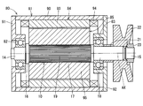
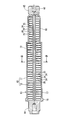
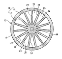
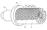
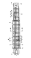
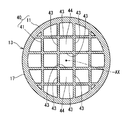
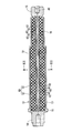
- FIG. 3 is a sectional view taken along line III-III in FIG. 2. It is a fragmentary sectional view showing the motor shaft by a 1st embodiment. It is a figure showing a motor shaft by a 2nd embodiment of this indication.
- FIG. 6 is a sectional view taken along line VI-VI in FIG. 5. It is sectional drawing of the motor shaft by 3rd Embodiment of this indication.
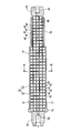
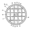
- FIG. 8 is a sectional view taken along line VIII-VIII in FIG. It is sectional drawing of the motor shaft by 4th Embodiment of this indication.
- FIG. 10 is a sectional view taken along line XX in FIG. 9. It is sectional drawing of the motor shaft by 5th Embodiment of this indication.
- FIG. 12 is a sectional view taken along line XII-XII in FIG. 11. It is a figure showing a motor shaft by a 6th embodiment of this indication. It is sectional drawing of the motor shaft by 6th Embodiment. It is the XV-XV sectional view taken on the line of FIG.
- FIG. 80 A motor to which the motor shaft according to the first embodiment of the present disclosure is applied is shown in FIG. First, a schematic configuration of the motor 80 will be described with reference to FIG.
- the motor 80 includes a housing 81, bearings 82 and 83, a stator 84 and a rotor 85.
- the housing 81 includes a cylindrical case 90, a first plate 91 provided so as to close one opening of the case 90, and a second plate 92 provided so as to close the other opening of the case 90. ing.
- the bearing 82 is provided at the center of the first plate 91.
- the bearing 83 is provided at the center of the second plate 92.
- the stator 84 has a stator core 93 fixed to the inner wall of the case 90, and a multi-phase coil 94 attached to the stator core 93.
- the rotor 85 includes a motor shaft 10 rotatably supported by bearings 82 and 83, and a rotor core 95 fixed to the outer wall of the motor shaft 10 by, for example, press-fitting.
- the rotor core 95 has a plurality of magnetic poles made of magnets (not shown).
- the motor 80 configured as described above, when the energized phase of the coil 94 is sequentially switched, a magnetic field that rotates around the axis AX of the motor shaft 10 is generated.
- the rotor 85 rotates around the axis AX when the magnetic pole is magnetically attracted to the rotating magnetic field.
- a direction parallel to the axis AX of the motor shaft 10 is referred to as “axial direction”.
- a direction perpendicular to the axis AX is referred to as a “radial direction”.
- a part of the shape that is originally visible behind the cross section is omitted.
- the motor shaft 10 includes a thin cylindrical outer portion 11 and an inner portion 12 provided inside the outer portion 11.
- the outer portion 11 includes a tube portion 13, one end portion 14 located on one side in the axial direction with respect to the tube portion 13, and the other end portion 15 located on the other side in the axial direction with respect to the tube portion 13.
- the cylindrical portion 13 is formed in a stepped shape, and has a flange portion 16, a large diameter portion 17, and a small diameter portion 18 in order from the one end portion 14 side.
- the large diameter portion 17 has an uneven knurled portion 19 formed on the outer wall, and is fitted inside the rotor core 95.
- the rotor core 95 is press-fitted until it comes into contact with the flange 16.
- the small diameter portion 18 is fitted inside the bearing 83.
- the collar 21 and the pulley 22 are fitted to the small diameter portion 18 on the other end 15 side with respect to the bearing 83.
- the large diameter portion 17 and the small diameter portion 18 are formed in a thin cylindrical shape.
- the one end portion 14 is fitted inside the bearing 82.
- a nut 23 is screwed to the other end portion 15.
- the pulley 22 is sandwiched between the collar 21 and the nut 23.
- the one end portion 14 and the other end portion 15 are closed. That is, no through hole is formed in the one end portion 14 and the other end portion 15. Since the through hole is not formed in the cylindrical portion 13, the inside of the outer portion 11 is sealed in a liquid-tight manner with respect to the outside.
- the inner part 12 is formed integrally with the outer part 11 from the same material as the outer part 11.
- the inner portion 12 is a structure including a plurality of support portions 24 coupled to each other, and has a gap 25 defined between the plurality of support portions 24.
- the inner portion 12 is a honeycomb structure in which a plurality of plate-like support portions 24 extending in the radial direction are gathered.
- the inner portion 12 is a honeycomb structure constituted by an assembly of a plurality of hollow columns extending radially from the axial center portion.
- the air gap 25 is mainly composed of a hollow portion inside the hollow column.
- the support portion 24 is thicker toward the inner side in the radial direction.
- the gap 25 has a smaller axial width and circumferential width as it goes inward in the radial direction.
- the bulk density becomes large, so that it goes to radial direction inner side.
- the inner portion 12 may have a higher density toward the radially inner side.
- the “honeycomb structure” is a structure in which a plurality of hollow columns are arranged without gaps.
- the cross-sectional shape of the hollow column is not limited to a hexagon, and may be another shape such as a quadrangle. In the present embodiment, the cross-sectional shape of the hollow column is a hexagon.
- the “bulk” of the object is the total of the volume occupied by the object itself, the volume of the hole opened in the object surface, and the volume of the void inside the object and closed to the outside.
- the “bulk density” is a value obtained by dividing the mass of an object by the bulk.
- the motor shaft 10 is formed by a 3D printer. Specifically, the motor shaft 10 is obtained by a method of three-dimensional modeling by irradiating laser to fine metal powder laid flat and layering one layer at a time and repeating this process (that is, powder sintering method). Molded. The gap 25 is formed simultaneously with the formation of the outer portion 11 and the inner portion 12. The point that the motor shaft is formed by a 3D printer is the same in the embodiments described later.
- the motor shaft 10 includes the thin cylindrical outer portion 11 and the inner portion 12 provided inside the outer portion 11.
- the inner portion 12 is formed of the same material as the outer portion 11 and is integrally formed with the outer portion 11, and is a structure including a plurality of support portions 24 that are coupled to each other, and is defined between the plurality of support portions 24. It has a gap 25.
- the outer portion 11 is supported by the inner portion 12 which is a structure, the strength of the motor shaft 10 can be ensured even if the outer portion 11 is thinned.
- the inner side part 12 is comprised lightweight by having the space
- the inner portion 12 has a larger bulk density as it goes inward in the radial direction. Therefore, it is possible to make the inner portion 12 a structure that can withstand the radial force acting when the rotor core 95 is press-fitted, for example, while making the support portion 24 as thin as possible so as to be lightweight.
- the outer portion 11 includes the cylindrical portion 13, one end portion 14 that seals one end of the cylindrical portion 13 in a liquid-tight manner, and the other end of the cylindrical portion 13 that is liquid-tightly sealed. And the other end 15.
- the inside of the outer side part 11 is sealed liquid-tight with respect to the exterior. Therefore, corrosion of the inside of the outer portion 11, that is, the inner portion 12, can be prevented.
- the inner portion 12 is a honeycomb structure in which a plurality of plate-like support portions 24 extending in the radial direction of the motor shaft 10 are gathered. Therefore, it is possible to make the inner portion 12 a structure that can withstand the radial force acting when the rotor core 95 is press-fitted, for example, while making the support portion 24 as thin as possible so as to be lightweight.
- the support portion 24 is thicker toward the inner side in the radial direction. In this manner, the bulk density of the inner portion 12 can be increased toward the inner side in the radial direction.
- the motor shaft 30 includes an outer portion 11 and an inner portion 31.
- the inner portion 31 is a honeycomb structure in which a plurality of plate-like support portions 32 formed in a spiral shape so as to extend in the axial direction while rotating around the axis AX.
- the inner portion 31 is a honeycomb structure constituted by an assembly of a plurality of spiral hollow columns that extend in the axial direction while rotating around the axis AX.
- the cross-sectional shape of the hollow column is a hexagon.
- the air gap 33 is a spiral hole formed of a hollow portion inside the hollow column. In FIG. 5, for convenience, only one support portion 32 is indicated by a broken line.
- the motor shaft 30 includes the thin cylindrical outer portion 11 and the inner portion 31 provided inside the outer portion 11.
- the inner portion 31 is formed of the same material as that of the outer portion 11 and is integrally formed with the outer portion 11, and is a structure including a plurality of support portions 32 coupled to each other, and is defined between the plurality of support portions 32. It has a gap 33. Therefore, according to the motor shaft 30, as in the first embodiment, the weight can be reduced while ensuring the strength.
- the inner portion 31 is a honeycomb structure in which a plurality of plate-like support portions 32 formed in a spiral shape so as to extend in the axial direction while rotating around the axis AX are gathered. Therefore, the strength against torsion of the motor shaft 30 is particularly increased.
- the motor shaft 40 includes an outer portion 11 and an inner portion 41.
- the inner portion 41 is a lattice structure formed by coupling a plurality of rod-shaped support portions 42 extending in the axial direction and a plurality of rod-shaped support portions 43 extending in a direction orthogonal to the axial direction.
- the inner portion 41 is a structure configured by an assembly of a plurality of hollow cubes.
- the support portions 42 and 43 extend in a direction that intersects the radial direction.
- a gap 44 defined between the support portions 42 and 43 is one space.
- the motor shaft 40 includes the thin-walled cylindrical outer portion 11 and the inner portion 41 provided inside the outer portion 11.
- the inner portion 41 is formed of the same material as that of the outer portion 11 and is integrally formed with the outer portion 11, and is a structure including a plurality of support portions 42 and 43 that are coupled to each other, and the plurality of support portions 42 and 43. It has an air gap 44 defined between them. Therefore, according to the motor shaft 40, as in the first embodiment, the weight can be reduced while ensuring the strength.
- the inner portion 41 is a lattice structure in which a plurality of support portions 42 and 43 are gathered.
- the support portions 42 and 43 extend in a direction that intersects the radial direction. Therefore, for example, the strength against a radial force such as centrifugal force is particularly increased.
- the motor shaft 50 includes an outer portion 51 and an inner portion 41.
- One end portion 52 of the outer portion 51 has a through hole 53
- the other end portion 54 has a through hole 55.
- the through holes 53 and 55 penetrate along the axial center AX in the axial direction.
- the gap 44 allows the through hole 53 and the through hole 55 to communicate with each other.
- the gap 44 and the through holes 53 and 55 are used as a cooling passage for circulating the coolant. Therefore, the motor shaft 50 can be efficiently cooled.
- the configuration of the motor shaft 50 other than the through holes 53 and 55 is the same as that of the third embodiment, and the same effect as that of the third embodiment can be obtained.
- the motor shaft 60 includes an outer portion 11 and an inner portion 61.
- the inner part 61 is a lattice structure in which a plurality of rod-like support parts 62 extending in an axial direction, a radial direction, and a direction intersecting with a virtual plane perpendicular to the axial direction are coupled to each other.
- the inner part 61 is a structure made up of an assembly of a plurality of hollow hexahedrons arranged so that a pair of diagonal corners are arranged in the radial direction.
- a gap 63 defined between the support portions 62 is one space.
- the motor shaft 60 includes the thin-walled cylindrical outer portion 11 and the inner portion 61 provided inside the outer portion 11.
- the inner portion 61 is formed of the same material as the outer portion 11 and is integrally formed with the outer portion 11, and is a structure including a plurality of support portions 62 coupled to each other, and is defined between the plurality of support portions 62. It has a gap 63. Therefore, according to the motor shaft 60, as in the first embodiment, the weight can be reduced while securing the strength.
- the inner portion 61 is a lattice structure in which a plurality of support portions 62 are gathered.
- the support portion 62 extends in the axial direction, the radial direction, and the direction intersecting the virtual plane perpendicular to the axial direction. Accordingly, the strength against axial and radial forces is particularly enhanced.
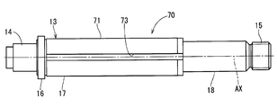
- the motor shaft 70 includes an outer portion 71 and an inner portion 72 as shown in FIGS. 13 to 15.
- a key groove 73 extending in the axial direction is formed on the outer wall of the outer portion 71.
- a key 74 is fitted in the key groove 73.
- the inner portion 72 is a structure in which a plurality of plate-like support portions 75 extending in a direction orthogonal to the extending direction of the key groove 73 are coupled to each other.
- the inner portion 72 is a honeycomb structure constituted by an assembly of a plurality of hollow columns extending in a direction orthogonal to the extending direction.
- the hollow pillar has a quadrangular cross-sectional shape. The hollow columns are arranged so that a pair of corners on a diagonal line of the cross section are aligned in the radial direction.
- the air gap 76 is a polygonal hole constituted by a hollow portion inside the hollow column.
- the motor shaft 70 includes the thin cylindrical outer portion 71 and the inner portion 72 provided inside the outer portion 71.
- the inner portion 72 is formed of the same material as that of the outer portion 71 and is integrally formed with the outer portion 71, and is a structure including a plurality of support portions 75 coupled to each other, and is defined between the plurality of support portions 75. It has a gap 76. Therefore, according to the motor shaft 70, as in the first embodiment, the weight can be reduced while ensuring the strength.
- the inner portion 72 is a honeycomb structure constituted by an assembly of a plurality of hollow columns extending in a direction orthogonal to the extending direction of the key groove 73.
- the cross section of the hollow column is a quadrangle.
- the hollow columns are arranged so that a pair of corners on a diagonal line of the cross section are aligned in the radial direction. Therefore, the strength against torsion of the motor shaft 70 is increased, and the strength against axial and radial forces is also increased.
- the key groove 73 is formed on the outer wall of the outer portion 71 as in the present embodiment, the circumferential force acting on the side wall of the key groove 73 via the key 74 by the rotational force of the heavy rotor core. Therefore, when the motor shaft 70 is about to twist, the inner portion 72 works to suppress the twist.
- the cylindrical part of the outer part of the motor shaft may not be stepped. Also, the stepped number of the outer cylindrical portion of the motor shaft may be three or more. Moreover, a part or all of the cylinder part of the outer side part of a motor shaft may be a taper shape.
- a hole penetrating in the radial direction may be provided in the outer cylindrical portion.
- the end of the motor shaft is not limited to a screw, and for example, a spline, a keyway or a gear may be formed. Further, a power transmission member other than the pulley may be fixed to the end of the motor shaft.
- the space inside the inner part is a space.
- Metal powder that has not been melted when the motor shaft is molded by a powder sintering method may be included in the gap.
- the tool holder is formed by a 3D printer, a method other than the powder sintering method may be used.
- the motor shaft is not limited to a synchronous motor but can be used for a motor such as a commutator motor or an induction motor. Furthermore, the motor shaft is not limited to one that generates a rotational force by electromagnetic force, and may be used for an ultrasonic motor or an electrostatic motor, for example.
Landscapes
- Engineering & Computer Science (AREA)
- Power Engineering (AREA)
- General Engineering & Computer Science (AREA)
- Manufacturing & Machinery (AREA)
- Ocean & Marine Engineering (AREA)
- Mechanical Engineering (AREA)
- Iron Core Of Rotating Electric Machines (AREA)
- Shafts, Cranks, Connecting Bars, And Related Bearings (AREA)
Abstract
モータシャフトは、モータ(80)のロータ(85)を構成する。モータシャフトは、薄肉筒状の外側部(11、51、71)と、外側部の内部に設けられる内側部(25、33、44、63、76)とを有する。内側部は、外側部と同じ材料から外側部と一体に形成されており、互いに結合している複数の支持部(24、32、42、43、62、75)と、複数の支持部によって区画された空隙とを有する。このモータシャフトによれば、強度を確保しつつ軽量化を図ることができる。
Description
本出願は、当該開示内容が参照によって本出願に組み込まれた、2015年12月17日に出願された日本特許出願2015-246220を基にしている。
本開示は、モータのロータを構成する回転軸であるモータシャフトに関する。
従来、例えば特許文献1に開示されているように、回転軸心に沿って延びる1つの軸方向穴を有する中空状のモータシャフトが知られている。モータシャフトは、外壁に固定されたロータコアと共にモータのロータを構成している。軸方向穴はモータシャフトの軽量化に貢献している。
モータシャフトの更なる軽量化のためには、軸方向穴の内径を大きくすればよい。しかし、モータシャフトの強度を確保することを考えた場合、軸方向穴の内径を大きくするには限界がある。
本開示の目的は、強度を確保しつつ軽量化を図ることができるモータシャフトを提供することである。
本開示の一態様によるモータシャフトは、モータのロータを構成する。モータシャフトは、薄肉筒状の外側部と、内側部とを有する。内側部は、外側部の内部に設けられており、外側部と同じ材料から外側部と一体に形成されており、互いに結合している複数の支持部と、複数の支持部によって区画された空隙とを有する。
以上より、構造体である内側部により外側部が支持されるので、外側部を薄肉化してもモータシャフトの強度を確保することができる。また、内側部は、空隙を有することで軽量に構成されている。したがって、本開示のモータシャフトによれば、強度を確保しつつ軽量化を図ることができる。さらに、複数の支持部が放熱フィンとして機能し、外側部から内側部に伝わる熱を空隙に放熱することができるので、モータシャフトを効果的に冷却することができる。
以下に、図面を参照しながら本開示を実施するための複数の形態を説明する。各形態において先行する形態で説明した事項に対応する部分には同一の参照符号を付して重複する説明を省略する場合がある。各形態において構成の一部のみを説明している場合は、構成の他の部分については先行して説明した他の形態を適用することができる。各実施形態で具体的に組合せが可能であることを明示している部分同士の組合せばかりではなく、特に組合せに支障が生じなければ、明示してなくとも実施形態同士を部分的に組み合せることも可能である。
[第1実施形態]
本開示の第1実施形態によるモータシャフトが適用されたモータを図1に示す。先ず、モータ80の概略構成について図1を参照して説明する。モータ80は、ハウジング81、軸受82、83、ステータ84およびロータ85を備えている。
本開示の第1実施形態によるモータシャフトが適用されたモータを図1に示す。先ず、モータ80の概略構成について図1を参照して説明する。モータ80は、ハウジング81、軸受82、83、ステータ84およびロータ85を備えている。
ハウジング81は、筒状のケース90と、ケース90の一方の開口を塞ぐように設けられた第1プレート91と、ケース90の他方の開口を塞ぐように設けられた第2プレート92とを備えている。軸受82は、第1プレート91の中央部に設けられている。軸受83は、第2プレート92の中央部に設けられている。
ステータ84は、ケース90の内壁に固定されたステータコア93と、ステータコア93に装着された複数相のコイル94とを有する。ロータ85は、軸受82、83により回転可能に支持されているモータシャフト10と、モータシャフト10の外壁に例えば圧入により固定されたロータコア95とを有する。ロータコア95は、図示しない磁石からなる複数の磁極を有する。
このように構成されたモータ80では、コイル94の通電相が順次切り替えられると、モータシャフト10の軸心AXまわりに回転する磁界が発生する。ロータ85は、磁極が上記回転磁界に磁気吸引されることにより軸心AXまわりに回転する。
次に、モータシャフト10の詳細な構成について図1~図4を参照して説明する。以下の説明では、モータシャフト10の軸心AXと平行な方向を「軸方向」と記載する。また、軸心AXと直交する方向を「径方向」と記載する。なお、図2~図4、および、後述の図5~図9では、煩雑になることを避けるために、一部において断面の奥に本来見える形状の図示を省略している。
モータシャフト10は、薄肉筒状の外側部11と、外側部11の内部に設けられている内側部12とを備えている。
外側部11は、筒部13と、筒部13に対して軸方向の一方に位置する一端部14と、筒部13に対して軸方向の他方に位置する他端部15とを有する。
本実施形態では、筒部13は、段付き状に形成されており、一端部14側から順に鍔部16、大径部17、および小径部18を有する。大径部17は、外壁に形成された凹凸状のローレット部19を有しており、ロータコア95の内側に嵌合している。ロータコア95は、鍔部16に当接するまで圧入されている。小径部18は、軸受83の内側に嵌合している。小径部18のうち軸受83に対して他端部15側には、カラー21およびプーリ22が嵌合している。大径部17および小径部18は、薄肉筒状に形成されている。
一端部14は、軸受82の内側に嵌合している。他端部15には、ナット23が螺合されている。プーリ22は、カラー21とナット23との間に挟持されている。本実施形態では、一端部14および他端部15は閉じている。つまり、一端部14および他端部15には貫通孔は形成されていない。筒部13にも貫通孔は形成されていないため、外側部11の内部は外部に対して液密に封止されている。
内側部12は、外側部11と同じ材料から当該外側部11と一体に形成されている。また、内側部12は、互いに結合している複数の支持部24からなる構造体であり、複数の支持部24間に区画された空隙25を有する。本実施形態では、内側部12は、径方向へ延びる板状の支持部24が複数集まってなるハニカム構造体である。言い換えれば、内側部12は、軸心部から放射状へ延びる複数の中空柱の集合体から構成されるハニカム構造体である。空隙25は、主として上記中空柱内部の空洞部分から構成されている。支持部24は、径方向の内側にいくほど厚みが厚い。また、空隙25は、径方向の内側にいくほど軸方向幅および周方向幅が小さい。これにより、内側部12は、径方向内側にいくほど嵩密度が大きくなっている。内側部12は、径方向内側ほど密度が大きくなっていても良い。
ここで、「ハニカム構造体」とは、複数の中空柱を隙間なく並べてなる構造体である。中空柱の横断面形状は、六角形に限らず、例えば四角形などの他の形状であってもよい。本実施形態では、中空柱の横断面形状は六角形である。
また、物体の「嵩」とは、物体自身が占める体積、物体表面に開口している穴の体積、および、物体内部にあり且つ外部に対して閉塞している空隙の体積の合計である。「嵩密度」とは、物体の質量を嵩で割った値である。
モータシャフト10は3Dプリンタにより成形されている。具体的には、平らに敷いた微細な金属粉末にレーザーを照射して一層ずつ焼結させ、この工程を繰り返すことで3次元造形する方法(すなわち、粉末焼結法)によって、モータシャフト10は成形されている。空隙25は、外側部11および内側部12の成形と同時に成形される。モータシャフトが3Dプリンタにより成形されているという点は、後述の実施形態においても同様である。
(効果)
以上説明したように、第1実施形態では、モータシャフト10は、薄肉筒状の外側部11と、外側部11の内部に設けられている内側部12とを備える。内側部12は、外側部11と同じ材料から当該外側部11と一体に形成されており、互いに結合している複数の支持部24からなる構造体であり、複数の支持部24間に区画された空隙25を有する。
以上説明したように、第1実施形態では、モータシャフト10は、薄肉筒状の外側部11と、外側部11の内部に設けられている内側部12とを備える。内側部12は、外側部11と同じ材料から当該外側部11と一体に形成されており、互いに結合している複数の支持部24からなる構造体であり、複数の支持部24間に区画された空隙25を有する。
以上より、構造体である内側部12により外側部11が支持されるので、外側部11を薄肉化してもモータシャフト10の強度を確保することができる。また、内側部12は、空隙25を有することで軽量に構成されている。したがって、モータシャフト10によれば、強度を確保しつつ軽量化を図ることができる。さらに、複数の支持部24が放熱フィンとして機能し、外側部11から内側部12に伝わる熱を空隙25に放熱することができるので、モータシャフト10を効果的に冷却することができる。
また、第1実施形態では、内側部12は、径方向の内側にいくほど嵩密度が大きい。したがって、軽量となるように支持部24をできるだけ薄肉化しつつも、内側部12を、例えばロータコア95の圧入時などに作用する径方向の力に耐えうる構造体とすることができる。
また、第1実施形態では、外側部11は、筒部13と、筒部13の一端を液密に封止している一端部14と、筒部13の他端を液密に封止している他端部15とを有する。これにより、外側部11の内部は外部に対して液密に封止される。したがって、外側部11の内部すなわち内側部12の腐食を防止することができる。
また、第1実施形態では、内側部12は、モータシャフト10の径方向へ延びる板状の支持部24が複数集まってなるハニカム構造体である。したがって、軽量となるように支持部24をできるだけ薄肉化しつつも、内側部12を、例えばロータコア95の圧入時などに作用する径方向の力に耐えうる構造体とすることができる。
また、第1実施形態では、支持部24は、径方向の内側にいくほど厚みが厚い。このようにして径方向の内側にいくほど内側部12の嵩密度を大きくすることができる。
[第2実施形態]
本開示の第2実施形態では、図5および図6に示すように、モータシャフト30は、外側部11および内側部31を備えている。内側部31は、軸心AXまわりに回転しながら軸方向へ延びるように螺旋状に形成された板状の支持部32が複数集まってなるハニカム構造体である。言い換えれば、内側部31は、軸心AXまわりに回転しながら軸方向へ延びる複数の螺旋状の中空柱の集合体から構成されるハニカム構造体である。本実施形態では、中空柱の横断面形状は六角形である。空隙33は、上記中空柱内部の空洞部分から構成される螺旋状の穴である。図5では、便宜上、1つの支持部32のみを破線で示している。
本開示の第2実施形態では、図5および図6に示すように、モータシャフト30は、外側部11および内側部31を備えている。内側部31は、軸心AXまわりに回転しながら軸方向へ延びるように螺旋状に形成された板状の支持部32が複数集まってなるハニカム構造体である。言い換えれば、内側部31は、軸心AXまわりに回転しながら軸方向へ延びる複数の螺旋状の中空柱の集合体から構成されるハニカム構造体である。本実施形態では、中空柱の横断面形状は六角形である。空隙33は、上記中空柱内部の空洞部分から構成される螺旋状の穴である。図5では、便宜上、1つの支持部32のみを破線で示している。
以上のように、モータシャフト30は、薄肉筒状の外側部11と、外側部11の内部に設けられている内側部31とを備える。内側部31は、外側部11と同じ材料から当該外側部11と一体に形成されており、互いに結合している複数の支持部32からなる構造体であり、複数の支持部32間に区画された空隙33を有する。したがって、モータシャフト30によれば、第1実施形態と同様に、強度を確保しつつ軽量化を図ることができる。
また、第2実施形態では、内側部31は、軸心AXまわりに回転しながら軸方向へ延びるように螺旋状に形成された板状の支持部32が複数集まってなるハニカム構造体である。したがって、モータシャフト30のねじれに対する強度が特に高められている。
[第3実施形態]
本開示の第3実施形態では、図7および図8に示すように、モータシャフト40は、外側部11および内側部41を備えている。内側部41は、軸方向へ延びる複数の棒状の支持部42と、軸方向に対して直交する方向へ延びる複数の棒状の支持部43とが結合してなる格子構造体である。言い換えれば、内側部41は、複数の中空立方体の集合体から構成される構造体である。支持部42、43は、径方向に対して交差する方向へ延びている。各支持部42、43の間に区画されている空隙44は、1つの空間である。
本開示の第3実施形態では、図7および図8に示すように、モータシャフト40は、外側部11および内側部41を備えている。内側部41は、軸方向へ延びる複数の棒状の支持部42と、軸方向に対して直交する方向へ延びる複数の棒状の支持部43とが結合してなる格子構造体である。言い換えれば、内側部41は、複数の中空立方体の集合体から構成される構造体である。支持部42、43は、径方向に対して交差する方向へ延びている。各支持部42、43の間に区画されている空隙44は、1つの空間である。
以上のように、モータシャフト40は、薄肉筒状の外側部11と、外側部11の内部に設けられている内側部41とを備える。内側部41は、外側部11と同じ材料から当該外側部11と一体に形成されており、互いに結合している複数の支持部42、43からなる構造体であり、複数の支持部42、43間に区画された空隙44を有する。したがって、モータシャフト40によれば、第1実施形態と同様に、強度を確保しつつ軽量化を図ることができる。
また、第3実施形態では、内側部41は、複数の支持部42、43が集まってなる格子構造体である。支持部42、43は、径方向に対して交差する方向へ延びている。したがって、例えば遠心力などの径方向の力に対する強度が特に高められている。
[第4実施形態]
本開示の第4実施形態では、図9および図10に示すように、モータシャフト50は、外側部51および内側部41を備えている。外側部51の一端部52は通孔53を有しており、また、他端部54は通孔55を有している。本実施形態では、通孔53、55は軸心AXに沿って軸方向へ貫通している。空隙44は、通孔53と通孔55とを連通させている。空隙44および通孔53、55は、冷却液を循環させる冷却通路として利用される。したがって、モータシャフト50を効率的に冷却することができる。
本開示の第4実施形態では、図9および図10に示すように、モータシャフト50は、外側部51および内側部41を備えている。外側部51の一端部52は通孔53を有しており、また、他端部54は通孔55を有している。本実施形態では、通孔53、55は軸心AXに沿って軸方向へ貫通している。空隙44は、通孔53と通孔55とを連通させている。空隙44および通孔53、55は、冷却液を循環させる冷却通路として利用される。したがって、モータシャフト50を効率的に冷却することができる。
また、モータシャフト50は、通孔53、55以外の構成は第3実施形態と同じであり、第3実施形態と同様の効果を得ることができる。
[第5実施形態]
本開示の第5実施形態では、図11および図12に示すように、モータシャフト60は、外側部11および内側部61を備えている。内側部61は、軸方向、径方向、および、軸方向に垂直な仮想面と交差する方向へ延びる複数の棒状の支持部62が互いに結合してなる格子構造体である。言い換えれば、内側部61は、対角線上の一対の角が径方向に並ぶように配置された複数の中空状の六面体の集合体からなる構造体である。各支持部62の間に区画されている空隙63は、1つの空間である。
本開示の第5実施形態では、図11および図12に示すように、モータシャフト60は、外側部11および内側部61を備えている。内側部61は、軸方向、径方向、および、軸方向に垂直な仮想面と交差する方向へ延びる複数の棒状の支持部62が互いに結合してなる格子構造体である。言い換えれば、内側部61は、対角線上の一対の角が径方向に並ぶように配置された複数の中空状の六面体の集合体からなる構造体である。各支持部62の間に区画されている空隙63は、1つの空間である。
以上のように、モータシャフト60は、薄肉筒状の外側部11と、外側部11の内部に設けられている内側部61とを備える。内側部61は、外側部11と同じ材料から当該外側部11と一体に形成されており、互いに結合している複数の支持部62からなる構造体であり、複数の支持部62間に区画された空隙63を有する。したがって、モータシャフト60によれば、第1実施形態と同様に、強度を確保しつつ軽量化を図ることができる。
また、第5実施形態では、内側部61は、複数の支持部62が集まってなる格子構造体である。支持部62は、軸方向、径方向、および、軸方向に垂直な仮想面と交差する方向へ延びている。したがって、軸方向および径方向の力に対する強度が特に高められている。
[第6実施形態]
本開示の第6実施形態では、図13~図15に示すように、モータシャフト70は、外側部71および内側部72を備えている。外側部71の外壁には、軸方向へ延びるキー溝73が形成されている。キー溝73にはキー74が嵌め込まれる。
本開示の第6実施形態では、図13~図15に示すように、モータシャフト70は、外側部71および内側部72を備えている。外側部71の外壁には、軸方向へ延びるキー溝73が形成されている。キー溝73にはキー74が嵌め込まれる。
内側部72は、キー溝73の延伸方向と直交する方向へ延びる複数の板状の支持部75が互いに結合してなる構造体である。言い換えれば、内側部72は、上記延伸方向と直交する方向へ延びる複数の中空柱の集合体から構成されるハニカム構造体である。本実施形態では、上記中空柱の横断面形状は四角形である。上記中空柱は、横断面の対角線上の一対の角が径方向に並ぶように配置されている。空隙76は、上記中空柱内部の空洞部分から構成される多角穴である。
以上のように、モータシャフト70は、薄肉筒状の外側部71と、外側部71の内部に設けられている内側部72とを備える。内側部72は、外側部71と同じ材料から当該外側部71と一体に形成されており、互いに結合している複数の支持部75からなる構造体であり、複数の支持部75間に区画された空隙76を有する。したがって、モータシャフト70によれば、第1実施形態と同様に、強度を確保しつつ軽量化を図ることができる。
また、第6実施形態では、内側部72は、キー溝73の延伸方向と直交する方向へ延びる複数の中空柱の集合体から構成されるハニカム構造体である。上記中空柱の横断面形状は四角形である。上記中空柱は、横断面の対角線上の一対の角が径方向に並ぶように配置されている。したがって、モータシャフト70のねじれに対する強度が高められているとともに、軸方向および径方向の力に対する強度も高められている。特に本実施形態のように外側部71の外壁にキー溝73が形成されている場合において、重量物であるロータコアの回転力によりキー74を介してキー溝73の側壁に作用する周方向の力によってモータシャフト70がねじれようとするとき、内側部72が上記ねじれを抑制するように働く。
モータシャフトの外側部の筒部は、段付き状でなくてもよい。また、モータシャフトの外側部の筒部の段付きの数は、3つ以上であってもよい。また、モータシャフトの外側部の筒部の一部または全部は、テーパ状であってもよい。
外側部の筒部に径方向に貫通する穴が設けられてもよい。
モータシャフトの端部は、ねじに限らず、例えばスプライン、キー溝またはギヤ等が形成されてもよい。また、モータシャフトの端部には、プーリ以外の動力伝達部材が固定されてもよい。
第1~第6実施形態では、内側部の空隙の中は空間であった。空隙の中に、粉末焼結法によりモータシャフトを成形するときに溶かされなかった金属粉末が内包されていてもよい。
工具ホルダを3Dプリンタによって成形するとき、粉末焼結法以外の方法を用いてもよい。
モータシャフトは、同期電動機に限らず、例えば整流子電動機または誘導電動機などのモータに用いられ得る。さらに、モータシャフトは、電磁力により回転力を生み出すものに限らず、例えば超音波モータまたは静電モータなどにも用いられ得る。
本開示は、上述した実施形態に限定されるものではなく、開示の趣旨を逸脱しない範囲で種々の形態で実施可能である。
本開示は、実施例に準拠して記述されたが、本開示は当該実施例や構造に限定されるものではないと理解される。本開示は、様々な変形例や均等範囲内の変形をも包含する。加えて、様々な組み合わせや形態、さらには、それらに一要素のみ、それ以上、あるいはそれ以下、を含む他の組み合わせや形態をも、本開示の範疇や思想範囲に入るものである。
Claims (9)
- モータ(80)のロータ(85)を構成するモータシャフトであって、
薄肉筒状の外側部(11、51、71)と、
前記外側部の内部に設けられており、前記外側部と同じ材料から当該外側部と一体に形成されており、互いに結合している複数の支持部(24、32、42、43、62、75)と、前記複数の支持部によって区画された空隙(25、33、44、63、76)とを有する内側部(12、31、41、61、72)と、
を備えるモータシャフト。 - 前記内側部(12)は、前記外側部の径方向の内側にいくほど嵩密度が大きい請求項1に記載のモータシャフト。
- 前記外側部は、筒部(13)と、当該筒部の一端を液密に封止している第1端部(14)と、前記筒部の他端を液密に封止している第2端部(15)とを有する請求項1または2に記載のモータシャフト。
- 前記外側部は、軸方向の端部である第1端部(52)および第2端部(54)を有し、
前記外側部の前記第1端部および前記第2端部は通孔(53、55)を有しており、
前記第1端部の前記通孔と前記第2端部の前記通孔とは、前記空隙を介して連通されている請求項1または2に記載のモータシャフト。 - 前記複数の支持部(24)は、前記外側部の径方向へ延びる板状を有し、
前記内側部(12)は、前記複数の支持部(24)によって形成されるハニカム構造体である請求項1~4のいずれか一項に記載のモータシャフト。 - 前記支持部は、前記径方向の内側にいくほど厚みが厚い請求項5に記載のモータシャフト。
- 前記複数の支持部(32)は、前記外側部の中心軸を軸として軸方向へ延びる螺旋状に形成された板状を有し、
前記内側部(31)は、前記複数の支持部(32)によって形成されるハニカム構造体である請求項1~4のいずれか一項に記載のモータシャフト。 - 前記複数の支持部(42、43、62、75)は棒状を有し、
前記内側部(41、61、72)は、前記複数の支持部(42、43、62、75)によって形成される格子構造体であり、
前記複数の支持部のうち少なくとも半分は、前記外側部の径方向に対して交差する方向へ延びている請求項1~4のいずれか一項に記載のモータシャフト。 - 前記外側部(71)の外壁には、前記外側部の軸方向へ延びるキー溝(73)が形成されており、
前記複数の支持部(75)は、前記キー溝の延伸方向に交差する方向へ延びる板状を有し、
前記内側部(72)は、前記複数の支持部(75)によって形成されるハニカム構造体である請求項1~4のいずれか一項に記載のモータシャフト。
Applications Claiming Priority (2)
| Application Number | Priority Date | Filing Date | Title |
|---|---|---|---|
| JP2015246220A JP6465014B2 (ja) | 2015-12-17 | 2015-12-17 | モータシャフト |
| JP2015-246220 | 2015-12-17 |
Publications (1)
| Publication Number | Publication Date |
|---|---|
| WO2017104560A1 true WO2017104560A1 (ja) | 2017-06-22 |
Family
ID=59056569
Family Applications (1)
| Application Number | Title | Priority Date | Filing Date |
|---|---|---|---|
| PCT/JP2016/086690 Ceased WO2017104560A1 (ja) | 2015-12-17 | 2016-12-09 | モータシャフト |
Country Status (2)
| Country | Link |
|---|---|
| JP (1) | JP6465014B2 (ja) |
| WO (1) | WO2017104560A1 (ja) |
Cited By (6)
| Publication number | Priority date | Publication date | Assignee | Title |
|---|---|---|---|---|
| CN107276329A (zh) * | 2017-08-01 | 2017-10-20 | 安徽达来电机有限公司 | 一种电机结构 |
| US20180175702A1 (en) * | 2016-12-16 | 2018-06-21 | Industrial Technology Research Institute | Motor shaft system with a cooling function |
| WO2020188162A1 (fr) | 2019-03-19 | 2020-09-24 | Psa Automobiles Sa | Arbre creux de rotor divise longitudinalement comportant au moins une ailette forgee s'etendant a l'interieur |
| EP3799264A1 (de) * | 2019-09-30 | 2021-03-31 | Siemens Aktiengesellschaft | Antriebswelle einer dynamoelektrischen maschine und deren herstellungsverfahren |
| CN114198383A (zh) * | 2022-01-15 | 2022-03-18 | 南昌航空大学 | 一种带蛛网状加强筋的空心轴 |
| WO2023083412A1 (de) * | 2021-11-12 | 2023-05-19 | MTU Aero Engines AG | Rotorwelle für einen elektromotor, anordnung für eine rotorwelle und verfahren zur fertigung einer anordnung für eine rotorwelle |
Families Citing this family (5)
| Publication number | Priority date | Publication date | Assignee | Title |
|---|---|---|---|---|
| CN111108666B (zh) * | 2017-09-22 | 2022-11-08 | Lg伊诺特有限公司 | 电机 |
| KR102531471B1 (ko) * | 2017-09-22 | 2023-05-11 | 엘지이노텍 주식회사 | 모터 |
| US11773746B2 (en) | 2021-09-10 | 2023-10-03 | Hamilton Sundstrand Corporation | Turbomachinery rotor shroud with variable lattice densities |
| US11994141B2 (en) * | 2021-09-10 | 2024-05-28 | Hamilton Sundstrand Corporation | Turbomachinery shaft with variable lattice densities |
| US11802488B2 (en) | 2021-09-10 | 2023-10-31 | Hamilton Sundstrand Corporation | Turbomachinery seal plate with variable lattice densities |
Citations (6)
| Publication number | Priority date | Publication date | Assignee | Title |
|---|---|---|---|---|
| JPS62818U (ja) * | 1985-06-18 | 1987-01-07 | ||
| JPS6261961U (ja) * | 1985-10-09 | 1987-04-17 | ||
| JPH06343245A (ja) * | 1991-08-15 | 1994-12-13 | Funchin U | 管軸式電動機 |
| JP2001316704A (ja) * | 2000-05-09 | 2001-11-16 | Hitachi Metals Ltd | 押出成形焼結体 |
| JP2006144607A (ja) * | 2004-11-18 | 2006-06-08 | Bay City Service Co Ltd | 無整流子直流電動機型ポンプ |
| US20070021224A1 (en) * | 2005-07-19 | 2007-01-25 | Patrascu Dumitru F | Propshafts with honeycomb core dampers |
Family Cites Families (3)
| Publication number | Priority date | Publication date | Assignee | Title |
|---|---|---|---|---|
| JP2004129407A (ja) * | 2002-10-03 | 2004-04-22 | Nissan Motor Co Ltd | 電動機の冷却構造 |
| JP5598378B2 (ja) * | 2011-02-28 | 2014-10-01 | アイシン・エィ・ダブリュ株式会社 | シャフト |
| JP2012235546A (ja) * | 2011-04-28 | 2012-11-29 | Nippon Soken Inc | ロータおよび回転電機 |
-
2015
- 2015-12-17 JP JP2015246220A patent/JP6465014B2/ja active Active
-
2016
- 2016-12-09 WO PCT/JP2016/086690 patent/WO2017104560A1/ja not_active Ceased
Patent Citations (6)
| Publication number | Priority date | Publication date | Assignee | Title |
|---|---|---|---|---|
| JPS62818U (ja) * | 1985-06-18 | 1987-01-07 | ||
| JPS6261961U (ja) * | 1985-10-09 | 1987-04-17 | ||
| JPH06343245A (ja) * | 1991-08-15 | 1994-12-13 | Funchin U | 管軸式電動機 |
| JP2001316704A (ja) * | 2000-05-09 | 2001-11-16 | Hitachi Metals Ltd | 押出成形焼結体 |
| JP2006144607A (ja) * | 2004-11-18 | 2006-06-08 | Bay City Service Co Ltd | 無整流子直流電動機型ポンプ |
| US20070021224A1 (en) * | 2005-07-19 | 2007-01-25 | Patrascu Dumitru F | Propshafts with honeycomb core dampers |
Cited By (10)
| Publication number | Priority date | Publication date | Assignee | Title |
|---|---|---|---|---|
| US20180175702A1 (en) * | 2016-12-16 | 2018-06-21 | Industrial Technology Research Institute | Motor shaft system with a cooling function |
| CN107276329A (zh) * | 2017-08-01 | 2017-10-20 | 安徽达来电机有限公司 | 一种电机结构 |
| WO2020188162A1 (fr) | 2019-03-19 | 2020-09-24 | Psa Automobiles Sa | Arbre creux de rotor divise longitudinalement comportant au moins une ailette forgee s'etendant a l'interieur |
| FR3094153A1 (fr) | 2019-03-19 | 2020-09-25 | Psa Automobiles Sa | Arbre de rotor comportant des ailettes integrees forgees et procede de fabrication de l’arbre de rotor |
| EP3799264A1 (de) * | 2019-09-30 | 2021-03-31 | Siemens Aktiengesellschaft | Antriebswelle einer dynamoelektrischen maschine und deren herstellungsverfahren |
| WO2021063745A1 (de) * | 2019-09-30 | 2021-04-08 | Siemens Aktiengesellschaft | Antriebswelle einer dynamoelektrischen maschine und deren herstellungsverfahren |
| EP3799264B1 (de) | 2019-09-30 | 2023-04-19 | Siemens Aktiengesellschaft | Antriebswelle einer dynamoelektrischen maschine |
| US12323009B2 (en) | 2019-09-30 | 2025-06-03 | Innomotics Gmbh | Drive shaft of a dynamoelectrical machine and corresponding manufacturing method |
| WO2023083412A1 (de) * | 2021-11-12 | 2023-05-19 | MTU Aero Engines AG | Rotorwelle für einen elektromotor, anordnung für eine rotorwelle und verfahren zur fertigung einer anordnung für eine rotorwelle |
| CN114198383A (zh) * | 2022-01-15 | 2022-03-18 | 南昌航空大学 | 一种带蛛网状加强筋的空心轴 |
Also Published As
| Publication number | Publication date |
|---|---|
| JP2017112764A (ja) | 2017-06-22 |
| JP6465014B2 (ja) | 2019-02-06 |
Similar Documents
| Publication | Publication Date | Title |
|---|---|---|
| JP6465014B2 (ja) | モータシャフト | |
| US12556046B2 (en) | Motor having non-circular stator | |
| US10873228B2 (en) | Rotor of an electric machine | |
| US20150380999A1 (en) | Permanent magnet machine | |
| US9768648B2 (en) | Rotor for electric machine | |
| KR101819005B1 (ko) | 모터 | |
| JP5061806B2 (ja) | アキシャルギャップ型回転電機 | |
| CN207782532U (zh) | 转子 | |
| CN113812064A (zh) | 转子和具有该转子的电动机 | |
| US20190372411A1 (en) | Rotor and motor using same | |
| JP7080278B2 (ja) | ロータ、ロータの製造方法及び回転電機 | |
| US20230006490A1 (en) | Rotor core and motor including the rotor core | |
| JP6826412B2 (ja) | 同期リラクタンス型回転電機 | |
| JP2011205753A (ja) | 電動機および電動機のロータの製造方法 | |
| JP4678321B2 (ja) | ロータの製造方法及び電動パワーステアリング用モータ | |
| JPWO2019150500A1 (ja) | 回転子部材、回転子及び回転電機 | |
| JP2009011051A (ja) | モータ | |
| JP2010246184A (ja) | ロータおよびモータ | |
| CN103683594A (zh) | 旋转电机 | |
| JP2008131742A (ja) | モータ | |
| JP2019071764A (ja) | ロータ、モータ及びロータの製造方法 | |
| JP2020092565A (ja) | 回転電機のロータ、及び回転電機 | |
| JP2008109800A (ja) | 回転子、リラクタンスモータ、回転子の製造方法及びリラクタンスモータの製造方法 | |
| JP5344749B2 (ja) | アキシャルギャップ型モータ及びそのロータ製造方法 | |
| KR101242468B1 (ko) | 원통형 전자기식 모터용 코어 및 이를 이용한 원통형 전자기식 모터 |
Legal Events
| Date | Code | Title | Description |
|---|---|---|---|
| 121 | Ep: the epo has been informed by wipo that ep was designated in this application |
Ref document number: 16875540 Country of ref document: EP Kind code of ref document: A1 |
|
| NENP | Non-entry into the national phase |
Ref country code: DE |
|
| 122 | Ep: pct application non-entry in european phase |
Ref document number: 16875540 Country of ref document: EP Kind code of ref document: A1 |