WO2017104499A1 - ガスセンサ - Google Patents
ガスセンサ Download PDFInfo
- Publication number
- WO2017104499A1 WO2017104499A1 PCT/JP2016/086326 JP2016086326W WO2017104499A1 WO 2017104499 A1 WO2017104499 A1 WO 2017104499A1 JP 2016086326 W JP2016086326 W JP 2016086326W WO 2017104499 A1 WO2017104499 A1 WO 2017104499A1
- Authority
- WO
- WIPO (PCT)
- Prior art keywords
- electrode
- gas
- sensor
- measured
- pump
- Prior art date
- Legal status (The legal status is an assumption and is not a legal conclusion. Google has not performed a legal analysis and makes no representation as to the accuracy of the status listed.)
- Ceased
Links
Images


Classifications
-
- G—PHYSICS
- G01—MEASURING; TESTING
- G01N—INVESTIGATING OR ANALYSING MATERIALS BY DETERMINING THEIR CHEMICAL OR PHYSICAL PROPERTIES
- G01N27/00—Investigating or analysing materials by the use of electric, electrochemical, or magnetic means
- G01N27/26—Investigating or analysing materials by the use of electric, electrochemical, or magnetic means by investigating electrochemical variables; by using electrolysis or electrophoresis
- G01N27/403—Cells and electrode assemblies
- G01N27/406—Cells and probes with solid electrolytes
- G01N27/407—Cells and probes with solid electrolytes for investigating or analysing gases
- G01N27/4071—Cells and probes with solid electrolytes for investigating or analysing gases using sensor elements of laminated structure
-
- G—PHYSICS
- G01—MEASURING; TESTING
- G01N—INVESTIGATING OR ANALYSING MATERIALS BY DETERMINING THEIR CHEMICAL OR PHYSICAL PROPERTIES
- G01N27/00—Investigating or analysing materials by the use of electric, electrochemical, or magnetic means
- G01N27/26—Investigating or analysing materials by the use of electric, electrochemical, or magnetic means by investigating electrochemical variables; by using electrolysis or electrophoresis
- G01N27/403—Cells and electrode assemblies
- G01N27/406—Cells and probes with solid electrolytes
- G01N27/407—Cells and probes with solid electrolytes for investigating or analysing gases
- G01N27/409—Oxygen concentration cells
-
- G—PHYSICS
- G01—MEASURING; TESTING
- G01N—INVESTIGATING OR ANALYSING MATERIALS BY DETERMINING THEIR CHEMICAL OR PHYSICAL PROPERTIES
- G01N27/00—Investigating or analysing materials by the use of electric, electrochemical, or magnetic means
- G01N27/26—Investigating or analysing materials by the use of electric, electrochemical, or magnetic means by investigating electrochemical variables; by using electrolysis or electrophoresis
- G01N27/403—Cells and electrode assemblies
- G01N27/406—Cells and probes with solid electrolytes
- G01N27/4067—Means for heating or controlling the temperature of the solid electrolyte
-
- G—PHYSICS
- G01—MEASURING; TESTING
- G01N—INVESTIGATING OR ANALYSING MATERIALS BY DETERMINING THEIR CHEMICAL OR PHYSICAL PROPERTIES
- G01N27/00—Investigating or analysing materials by the use of electric, electrochemical, or magnetic means
- G01N27/26—Investigating or analysing materials by the use of electric, electrochemical, or magnetic means by investigating electrochemical variables; by using electrolysis or electrophoresis
- G01N27/403—Cells and electrode assemblies
- G01N27/406—Cells and probes with solid electrolytes
- G01N27/407—Cells and probes with solid electrolytes for investigating or analysing gases
- G01N27/41—Oxygen pumping cells
-
- G—PHYSICS
- G01—MEASURING; TESTING
- G01N—INVESTIGATING OR ANALYSING MATERIALS BY DETERMINING THEIR CHEMICAL OR PHYSICAL PROPERTIES
- G01N27/00—Investigating or analysing materials by the use of electric, electrochemical, or magnetic means
- G01N27/26—Investigating or analysing materials by the use of electric, electrochemical, or magnetic means by investigating electrochemical variables; by using electrolysis or electrophoresis
- G01N27/416—Systems
- G01N27/4163—Systems checking the operation of, or calibrating, the measuring apparatus
-
- G—PHYSICS
- G01—MEASURING; TESTING
- G01N—INVESTIGATING OR ANALYSING MATERIALS BY DETERMINING THEIR CHEMICAL OR PHYSICAL PROPERTIES
- G01N27/00—Investigating or analysing materials by the use of electric, electrochemical, or magnetic means
- G01N27/26—Investigating or analysing materials by the use of electric, electrochemical, or magnetic means by investigating electrochemical variables; by using electrolysis or electrophoresis
- G01N27/416—Systems
- G01N27/417—Systems using cells, i.e. more than one cell and probes with solid electrolytes
- G01N27/419—Measuring voltages or currents with a combination of oxygen pumping cells and oxygen concentration cells
Definitions
- the present invention relates to a gas sensor for measuring the concentration of a specific gas component in a gas to be measured such as exhaust gas.
- Patent Document 1 discloses a gas sensor that measures the concentration of a specific gas component other than oxygen in exhaust gas.
- the gas sensor disclosed in Patent Document 1 includes a pump electrode that adjusts the oxygen concentration of exhaust gas (that is, the gas to be measured) on the surface in contact with the gas chamber to be measured in the solid electrolyte body, and after the oxygen concentration is adjusted.
- the monitor electrode for monitoring the residual oxygen concentration in the exhaust gas and the sensor electrode for detecting the concentration of the specific gas component in the exhaust gas after the oxygen concentration is adjusted are arranged. Further, the monitor electrode and the sensor electrode are arranged adjacent to each other on the downstream side of the pump electrode with respect to the flow of the gas to be measured in the gas chamber to be measured.
- the pump electrode lead portion for energizing the pump electrode is disposed adjacent to the side of the sensor electrode. For this reason, the current flowing through the sensor electrode according to the concentration of the specific gas component may vary due to the influence of electrical noise based on the leakage of the current flowing through the pump electrode. For this reason, further improvement is required to increase the detection accuracy of the concentration of the specific gas component.
- the present invention has been made in view of such problems, and an object of the present invention is to provide a gas sensor capable of increasing the detection accuracy of the concentration of a specific gas component in a gas to be measured.
- a gas sensor includes: A solid electrolyte plate having oxygen ion conductivity; A gas chamber to be measured formed adjacent to the first surface of the solid electrolyte plate; A pump electrode provided on the first surface of the solid electrolyte plate so as to be exposed to the gas to be measured in the gas chamber to be measured; Monitors provided adjacent to each other at a position downstream of the pump electrode with respect to the flow of the gas to be measured on the first surface of the solid electrolyte plate so as to be exposed to the gas to be measured in the gas chamber to be measured.
- An electrode and a sensor electrode At least one reference electrode provided on a second surface of the solid electrolyte plate opposite the first surface to be exposed to a reference gas;
- a heater that is disposed opposite the second surface of the solid electrolyte plate and heats the solid electrolyte plate;
- a pump cell unit that adjusts the oxygen concentration of the gas to be measured in the gas chamber to be measured when a voltage is applied between the pump electrode and the reference electrode via the first portion of the solid electrolyte plate; The current flowing through the second part of the solid electrolyte plate is detected between the monitor electrode and the reference electrode, and the residual oxygen concentration in the gas to be measured after the oxygen concentration is adjusted by the pump electrode is detected.
- a sensor cell unit for detecting In the width direction orthogonal to the direction of the flow of the gas to be measured, the monitor electrode is disposed between the sensor electrode and the pump electrode lead portion extending from the pump electrode toward the downstream side of the flow of the gas to be measured.
- the pump electrode lead portion and the sensor electrode lead portion extending from the sensor electrode toward the downstream side with respect to the flow of the gas to be measured toward the downstream side with respect to the flow of the gas to be measured from the monitor electrode.
- Extending monitor electrode lead part is arranged, A space of 0.5 mm or more is provided between the upstream portion of the pump electrode lead portion including the portion facing the monitor electrode from the width direction and the monitor electrode lead portion.
- the arrangement relationship between the pump electrode lead portion and the sensor electrode is devised. Specifically, a monitor electrode is disposed between the pump electrode lead portion and the sensor electrode in the width direction orthogonal to the direction of the flow of the gas to be measured. A monitor electrode lead portion is disposed between the pump electrode lead portion and the sensor electrode lead portion.
- the specific gas component detected by the sensor cell unit is only slightly present in the gas to be measured, and the current flowing through the sensor cell unit when the specific gas component is decomposed at the sensor electrode is weak.
- the current flowing through the pump cell part flows when oxygen contained in the gas to be measured such as exhaust gas is reduced, and is significantly larger than the current flowing through the sensor cell part.
- the sensor electrode that detects a weak current is kept away from the pump electrode lead portion through which a large current flows, so that the sensor cell portion is less susceptible to the influence of electrical noise generated when a current flows through the pump electrode lead portion.
- a monitor electrode is interposed between the pump electrode lead portion and the sensor electrode. As a result, the monitor electrode serves to guard the sensor electrode, and the influence of electrical noise generated from the pump electrode lead portion on the sensor electrode can be reduced.
- the concentration of the specific gas component in the gas to be measured after the oxygen concentration is adjusted by the pump electrode, but also the residual oxygen concentration is detected.
- the gas sensor by subtracting the output of the monitor cell unit from the output of the sensor cell unit, the influence of the residual oxygen concentration in the gas to be measured after the oxygen concentration is adjusted on the concentration of the specific gas component can be reduced. .
- the monitor cell unit is used for correcting the detection of the concentration of the specific gas component by reducing the influence of the residual oxygen concentration, and does not directly detect the concentration of the specific gas component. Therefore, the sensor electrode is affected by the electrical noise generated from the pump electrode lead, and the monitor electrode is affected by the electrical noise generated from the pump electrode lead, compared to the error that occurs in the detection of the concentration of the specific gas component. Accordingly, the error that occurs in the detection of the concentration of the specific gas component is small.
- the detection accuracy of the concentration of the specific gas component can be increased by interposing the monitor electrode between the pump electrode lead portion and the sensor electrode.
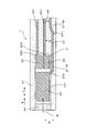
- FIG. 2 is a schematic cross-sectional view of the gas sensor taken along the line II-II in FIG. 1.
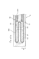
- FIG. 3 is a schematic cross-sectional view of the gas sensor as viewed in the direction of arrows III-III in FIG. 1.
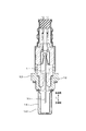
- FIG. 4 is a schematic cross-sectional view of the gas sensor as viewed in the direction of arrows IV-IV in FIG. 1.
- the typical sectional view showing the whole gas sensor composition concerning an embodiment.
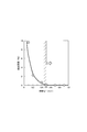
- the graph which shows the relationship between the space
- the gas sensor 1 includes a solid electrolyte plate 2, a gas chamber to be measured 101, a pump electrode 21, a monitor electrode 22, a sensor electrode 23, a reference electrode 24, a heater 5, and a pump cell unit. 31, a monitor cell unit 32 and a sensor cell unit 33.
- the solid electrolyte plate 2 has oxygen ion conductivity and is formed in a plate shape.
- the gas chamber 101 to be measured is formed adjacent to the first surface 201 of the solid electrolyte plate 2.
- the pump electrode 21 is provided on the first surface 201 of the solid electrolyte plate 2 and is exposed to the measured gas G in the measured gas chamber 101.
- the monitor electrode 22 and the sensor electrode 23 are provided adjacent to each other on the first surface 201 of the solid electrolyte plate 2 at a position downstream of the pump electrode 21 with respect to the flow of the gas G to be measured. It is exposed to the measurement gas G in the gas chamber 101.
- the reference electrode 24 is provided on the second surface 202 of the solid electrolyte plate 2 on the opposite side of the first surface 201 and is exposed to the reference gas A.
- the heater 5 is disposed opposite to the second surface 202 of the solid electrolyte plate 2 and heats the solid electrolyte plate 2.
- the pump cell unit 31 adjusts the oxygen concentration of the measured gas G in the measured gas chamber 101 when a voltage is applied between the pump electrode 21 and the reference electrode 24 via the first portion 2A of the solid electrolyte plate 2. To do.
- the monitor cell unit 32 detects the current flowing between the monitor electrode 22 and the reference electrode 24 through the second portion 2B of the solid electrolyte plate 2 and the gas to be measured after the oxygen concentration is adjusted by the pump electrode 21 The residual oxygen concentration in G is detected.
- the sensor cell unit 33 detects a current flowing between the sensor electrode 23 and the reference electrode 24 via the third portion 2C of the solid electrolyte plate 2, and the gas to be measured after the oxygen concentration is adjusted by the pump electrode 21 The concentration of a specific gas component other than oxygen in G is detected.
- the pump electrode extending from the pump electrode 21 toward the downstream side of the flow of the measurement gas G in the width direction W orthogonal to the flow direction F of the measurement gas G in the measurement gas chamber 101.
- a monitor electrode 22 is disposed between the lead portion 211 and the sensor electrode 23. Between the pump electrode lead portion 211 and the sensor electrode lead portion 231 extending from the sensor electrode 23 toward the downstream side of the flow of the measurement gas G, the downstream side of the flow of the measurement gas G from the monitor electrode 22 A monitor electrode lead portion 221 extending toward is disposed.
- a gap w1 of 0.5 mm or more is provided between the upstream electrode portion 211A including the portion facing the monitor electrode 22 from the width direction W in the pump electrode lead portion 211 and the monitor electrode lead portion 221.
- the gas sensor 1 is used by being disposed in an exhaust passage of an internal combustion engine in a vehicle, and detects the concentration of NOx (nitrogen oxide) as a specific gas component contained in the exhaust gas using the exhaust gas flowing through the exhaust passage as the gas to be measured G. To do.
- the gas sensor 1 constitutes a sensor element and is formed in a long shape. A proximal end portion in the longitudinal direction L of the gas sensor 1 is held by an insulator 12, and the insulator 12 is held by a housing 13 attached to the internal combustion engine.
- a detection unit 11 into which the gas G to be measured flows is provided at the distal end portion in the longitudinal direction L of the gas sensor 1, and the detection unit 11 is covered by a protective cover 14 provided with a through hole 141. ing.
- the gas chamber 101 to be measured, the pump electrode 21, the monitor electrode 22, the sensor electrode 23, the reference electrode 24, the heater 5, the pump cell unit 31, the monitor cell unit 32, and the sensor cell unit 33 are provided in the detection unit 11.
- the distal end side in the longitudinal direction L of the gas sensor 1 corresponds to the upstream side with respect to the flow of the measured gas G in the measured gas chamber 101
- the proximal end side in the longitudinal direction L of the gas sensor 1 is This corresponds to the downstream side of the flow of the measurement gas G in the measurement gas chamber 101.
- the solid electrolyte plate 2 is made of yttria-stabilized zirconia, and only one is disposed in the gas sensor 1.
- a second insulating plate 42 is laminated on the first surface 201 of the solid electrolyte plate 2 with a notched first insulating plate 41 for forming the gas chamber 101 to be measured.
- the first insulating plate 41 and the second insulating plate 42 are made of an insulator such as alumina.
- the first insulating plate 41 is provided on the base end side portion in the longitudinal direction L and the both side portions in the width direction W on the first surface 201 of the solid electrolyte plate 2.
- An opening is formed in the distal end portion of the first insulating plate 41 in the longitudinal direction L, and a diffusion resistor 44 made of a porous body is disposed in the opening.
- the measured gas chamber 101 is formed between the first surface 201 of the solid electrolyte plate 2 and the second insulating plate 42 so as to be surrounded by the diffusion resistor 44 and the first insulating plate 41.
- the measured gas G flows into the measured gas chamber 101 via the diffusion resistor 44.
- the pump electrode 21, the monitor electrode 22, the sensor electrode 23, and the reference electrode 24 are provided on the same solid electrolyte plate 2.
- the pump electrode 21 is positioned upstream of the flow of the gas G to be measured in the gas chamber 101 to be measured and is closer to the diffusion resistor 44 than the monitor electrode 22 and the sensor electrode 23.
- the monitor electrode 22 and the sensor electrode 23 are formed to have the same size and are disposed at the same distance from the pump electrode 21.
- the arrangement conditions of the monitor electrode 22 and the sensor electrode 23 are made equal to the flow of the measurement gas G after passing through the arrangement position of the pump electrode 21 in the measurement gas chamber 101.
- One reference electrode 24 is provided at a position facing the pump electrode 21, the monitor electrode 22, and the sensor electrode 23 as a whole. In addition, three reference electrodes 24 can be separately provided at positions facing the pump electrode 21, the monitor electrode 22, and the sensor electrode 23.
- the pump electrode 21 and the monitor electrode 22 are made of a cermet material containing a metal component such as a Pt—Au alloy that can decompose oxygen and not decompose a specific gas component.
- the sensor electrode 23 is made of oxygen and a specific gas.
- a cermet material containing a metal component such as a Pt—Rh alloy capable of decomposing the component is used.
- the reference electrode 24 is configured using a cermet material containing a metal component such as Pt capable of decomposing oxygen.
- the heater 5 includes two ceramic substrates 51 such as alumina, and a conductor layer 52 embedded between the two ceramic substrates 51.
- the heater 5 is laminated on the second surface 202 of the solid electrolyte plate 2 via a third insulating plate 43 for forming a reference gas chamber 102 into which the atmosphere as the reference gas A is introduced.
- the third insulating plate 43 is made of an insulator such as alumina.
- the third insulating plate 43 is formed in a notch shape having an opening at the base end in the longitudinal direction L of the gas sensor 1.
- the reference gas chamber 102 is formed between the second surface 202 of the solid electrolyte plate 2 and the ceramic substrate 51 so as to be surrounded on three sides by the third insulating plate 43.
- the reference gas A flows into the reference gas chamber 102 from the proximal end portion in the longitudinal direction L of the gas sensor 1.
- the conductor layer 52 of the heater 5 connects the pair of lead parts 521 connected to the energization means outside the gas sensor 1 and the pair of lead parts 521, and is applied to the pair of lead parts 521.
- a heat generating portion 522 that generates heat when energized by voltage.
- the heat generating portion 522 mainly generates heat due to Joule heat.
- the pump electrode 21, the monitor electrode 22, and the sensor electrode 23 are heated to a desired operating temperature by the heat generated by the heat generating unit 522.
- the resistance value of the heat generating part 522 is larger than the resistance value of the lead part 521.
- the resistance value of the heat generating portion 522 can occupy 50% or more of the resistance value of the entire conductor layer 52.
- the heat generating portion 522 is provided at a position facing substantially the entire planar area where the pump electrode 21, the monitor electrode 22, and the sensor electrode 23 are disposed.
- the resistance value of the heat generating part 522 can be made larger than the resistance value of the lead part 521 by making the pattern wiring of the heat generating part 522 thinner than the pattern wiring of the lead part 521. Further, the heat generation portion 522 can also generate heat by making the film thickness of the heat generation portion 522 smaller than the film thickness of the lead portion 521 or by making the material of the heat generation portion 522 larger in specific resistance than the material of the lead portion 521. The resistance value of the part 522 can be made larger than the resistance value of the lead part 521. In addition, the resistance value of the heat generating part 522 can be made larger than the resistance value of the lead part 521 by combining techniques for changing the thickness, film thickness, constituent material, and the like of the pattern wiring.
- the pump cell unit 31 includes a pump electrode 21, a part of the reference electrode 24, and a first part 2 ⁇ / b> A of the solid electrolyte plate 2 sandwiched between the pump electrode 21 and a part of the reference electrode 24. And is composed of.
- a voltage application circuit 61 for applying a voltage between the electrodes 21 and 24 is provided.
- oxygen in the gas G to be measured that contacts the pump electrode 21 is decomposed and passed through the solid electrolyte plate 2. Oxygen ions permeate the reference electrode 24, and oxygen in the measurement gas G in the measurement gas chamber 101 is reduced.
- the monitor cell unit 32 includes a monitor electrode 22, a part of the reference electrode 24, and a second part of the solid electrolyte plate 2 sandwiched between the monitor electrode 22 and a part of the reference electrode 24. 2B.
- a first current detection circuit for detecting a current flowing between the electrodes 22 and 24 between the monitor electrode 22 and the reference electrode 24 in a state where a predetermined voltage is applied between the electrodes 22 and 24. 62 is provided. When residual oxygen in the measurement gas G that contacts the monitor electrode 22 is decomposed, oxygen ions permeate the reference electrode 24 through the solid electrolyte plate 2. At this time, the current flowing between the monitor electrode 22 and the reference electrode 24 via the second portion 2B of the solid electrolyte plate 2 is detected by the first current detection circuit 62.
- the sensor cell part 33 includes a sensor electrode 23, a part of the reference electrode 24, and a third part of the solid electrolyte plate 2 sandwiched between the sensor electrode 23 and a part of the reference electrode 24. 2C.
- a second current detection circuit that detects a current flowing between the electrodes 23 and 24 in a state where a predetermined voltage is applied between the electrodes 23 and 24. 63 is provided.
- oxygen ions permeate the reference electrode 24 through the solid electrolyte plate 2.
- the current flowing between the sensor electrode 23 and the reference electrode 24 via the third portion 2C of the solid electrolyte plate 2 is detected by the second current detection circuit 63.
- movement of the gas sensor 1 the influence of the residual oxygen in the waste gas which is the to-be-measured gas G is relieve
- the concentration of NOx that is the specific gas component is obtained.
- the pump electrode lead portion 211 is formed on the first surface 201 of the solid electrolyte plate 2 so as to be connected to the pump electrode 21.
- the pump electrode lead portion 211 is for connecting the pump electrode 21 to the voltage application circuit 61.
- the pump electrode lead 211 is displaced from the downstream end of one side surface in the width direction W of the pump electrode 21 to one side in the width direction W, and the flow of the gas G to be measured in the gas chamber 101 to be measured. Is provided toward the downstream side (the base end side in the longitudinal direction L of the gas sensor 1).
- the entire pump electrode lead portion 211 excluding the portion 212 connected to the pump electrode 21 is embedded between the solid electrolyte plate 2 and the first insulating plate 41.
- the entire downstream portion 211B located on the downstream side with respect to the flow of the gas G is embedded between the solid electrolyte plate 2 and the first insulating plate 41.
- the pump electrode lead portion 211 can be enclosed by the solid electrolyte plate 2 and the first insulating plate 41.
- the monitor electrode lead portion 221 extending from the monitor electrode 22 toward the downstream side of the flow of the gas G to be measured is connected to the downstream end portion of the monitor electrode 22.
- the monitor electrode lead 221 is for connecting the monitor electrode 22 to the first current detection circuit 62.
- the monitor electrode lead part 221 is linearly provided toward the downstream side of the flow of the gas G to be measured.
- the whole of the monitor electrode lead part 221 except the portion 222 connected to the monitor electrode 22 is embedded between the solid electrolyte plate 2 and the first insulating plate 41.
- a sensor electrode lead portion 231 extending from the sensor electrode 23 toward the downstream side of the flow of the gas G to be measured is connected to the downstream end portion of the sensor electrode 23.
- the sensor electrode lead portion 231 is for connecting the sensor electrode 23 to the second current detection circuit 63.
- the sensor electrode lead portion 231 is linearly provided toward the downstream side with respect to the flow of the gas G to be measured.
- the entire sensor electrode lead portion 231 except the portion 232 connected to the sensor electrode 23 is buried between the solid electrolyte plate 2 and the first insulating plate 41.
- the monitor electrode lead portion 221 is disposed between the pump electrode lead portion 211 and the sensor electrode lead portion 231 in the width direction W of the gas sensor 1.
- the monitor electrode lead portion 221 is connected to the monitor electrode 22 while being biased to the side away from the pump electrode lead portion 211. More specifically, the monitor electrode lead portion 221 is connected to a position farthest from the pump electrode lead portion 211 at the downstream end portion of the monitor electrode 22. With this configuration, the monitor electrode lead portion 221 can be easily moved away from the pump electrode lead portion 211.
- the sensor electrode lead portion 231 is connected to the sensor electrode 23 while being biased to the side away from the pump electrode lead portion 211.
- the sensor electrode lead portion 231 is connected to a position farthest from the pump electrode lead portion 211 at the downstream end portion of the sensor electrode 23. With this configuration, it becomes easy to move the sensor electrode lead portion 231 away from the pump electrode lead portion 211.
- the interval w1 between the upstream portion 211A of the pump electrode lead portion 211 and the monitor electrode lead portion 221 is the interval between the downstream portion 211B of the pump electrode lead portion 211 and the monitor electrode lead portion 221. Greater than w2.
- the upstream portion 211A of the pump electrode lead portion 211 is arranged around the one side in the width direction W so as to be away from the monitor electrode 22, and the downstream portion 211B of the pump electrode lead portion 211 is disposed upstream. It is arranged closer to the monitor electrode lead portion 221 than the portion 211A.
- an interval w1 of 0.5 mm or more is provided between the upstream portion 211A of the pump electrode lead portion 211 and the monitor electrode lead portion 221. This interval w1 can be set to 1.5 mm or less in consideration of the size of the gas sensor 1 actually manufactured.
- the pump electrode 21, the monitor electrode 22, and the sensor electrode 23 are heated to 650 ° C. or more by the heat generating part 522 of the heater 5.
- the center of heating by the heat generating part 522 of the heater 5 is set at a position facing the pump electrode 21.
- the upstream portion 211 ⁇ / b> A of the pump electrode lead portion 211 is heated to 650 ° C. or more by the heat generating portion 522 of the heater 5.
- the front end portion of the gas sensor 1 is in a high temperature region of 650 ° C. or higher, and is easily affected by electrical noise generated from the pump electrode lead portion 211 when a current is passed through the pump electrode 21 due to the high temperature. .
- the pump electrode lead portion 211 can be separated from the monitor electrode 22 and the sensor electrode 23 as much as possible by diverting the upstream portion 211A of the pump electrode lead portion 211 from the monitor electrode 22 to one side in the width direction W. Further, when the arrangement position of the pump electrode lead portion 211 is too close to the outer end face in the width direction W between the solid electrolyte plate 2 and the first insulating plate 41, the solid electrolyte plate 2 and the first insulating plate 41 are arranged. It becomes easy to produce the trouble at the time of joining. In this case, the measurement gas G leaks easily from the measurement gas chamber 101 to the outside of the gas sensor 1. Therefore, the downstream portion 211 ⁇ / b> B of the pump electrode lead portion 211 is disposed at a position close to the monitor electrode lead portion 221.
- the pump electrode lead part 211, the monitor electrode lead part 221 and the sensor electrode lead part 231 are made of a cermet material containing a metal component such as Pt.
- Each lead portion is provided up to the base end portion in the longitudinal direction L of the gas sensor 1 and is electrically connected to a control device outside the gas sensor 1 via a metal fitting, a lead wire, and the like.
- the monitor electrode 22 and the monitor electrode lead part 221 are arranged between the pump electrode lead part 211 and the sensor electrode 23 and the sensor electrode lead part 231 in the width direction W of the gas sensor 1.
- the specific gas component such as NOx detected by the sensor cell unit 33 is only slightly present in the measured gas G such as exhaust gas, and the current flowing through the sensor cell unit 33 when the specific gas component is decomposed at the sensor electrode 23 is It is weak.
- the current flowing through the pump cell unit 31 flows when the oxygen contained in the measurement gas G is reduced, and is significantly larger than the current flowing through the sensor cell unit 33.
- the sensor electrode 23 for detecting a weak current is moved away from the pump electrode lead part 211 through which a large current flows, so that the sensor cell part 33 causes a leakage current or the like generated when a current flows through the pump electrode lead part 211. It can be made less susceptible to the effects of electrical noise.
- the monitor electrode 22 is interposed between the pump electrode lead portion 211 and the sensor electrode 23. Thereby, the monitor electrode 22 plays a role of guarding the sensor electrode 23, and the influence of electrical noise generated from the pump electrode lead portion 211 on the sensor electrode 23 can be reduced.
- the monitor cell unit 32 is used for correcting the detection of the concentration of the specific gas component by reducing the influence of the residual oxygen concentration, and directly detects the concentration of the specific gas component. It is not a thing. Therefore, the sensor electrode 23 is affected by the electrical noise generated from the pump electrode lead portion 211, and the monitor electrode 22 is electrically generated from the pump electrode lead portion 211 as compared with the error generated in the detection of the concentration of the specific gas component. The error that occurs in the detection of the concentration of a specific gas component due to the influence of noise is small.
- the following effects can be obtained by interposing the monitor electrode 22 between the pump electrode lead portion 211 and the sensor electrode 23 in the width direction W of the gas sensor 1.
- the gas sensor 1 when the laminated body in which the solid electrolyte plate 2, the insulating plates 41, 42, 43, the heater 5, etc. are laminated, or when the gas sensor 1 is used, a high temperature environment is used. There is a possibility that the metal components and the like of the pump electrode lead part 211 exposed to the vaporization may volatilize.
- FIG. 6 an error in the concentration of nitric oxide detected by the gas sensor 1 with respect to the actual concentration of nitric oxide is shown as a detection error.
- the detection error increases as the interval w1 between the upstream portion 211A of the pump electrode lead portion 211 and the monitor electrode lead portion 221 decreases.
- the detection error increases rapidly.
- the interval w1 between the lead portions 211A and 221 is smaller than 0.5 mm, the electrical insulation between the upstream portion 211A of the pump electrode lead portion 211 and the monitor electrode lead portion 221 decreases. This is considered to be because the leakage current generated between these lead portions 211A and 221 is increased.
- the arrangement relationship between the pump electrode lead portion 211, the sensor electrode 23, and the monitor electrode 22 is made appropriate, and the distance between the upstream portion 211A of the pump electrode lead portion 211 and the monitor electrode 22 is increased. It is important to make w1 appropriate.
- the present invention is not limited to the above-described embodiments, and can be implemented in various forms without departing from the scope of the invention.
Landscapes
- Chemical & Material Sciences (AREA)
- Life Sciences & Earth Sciences (AREA)
- Health & Medical Sciences (AREA)
- Physics & Mathematics (AREA)
- Chemical Kinetics & Catalysis (AREA)
- Electrochemistry (AREA)
- Molecular Biology (AREA)
- Analytical Chemistry (AREA)
- Biochemistry (AREA)
- General Health & Medical Sciences (AREA)
- General Physics & Mathematics (AREA)
- Immunology (AREA)
- Pathology (AREA)
- Measuring Oxygen Concentration In Cells (AREA)
Priority Applications (2)
| Application Number | Priority Date | Filing Date | Title |
|---|---|---|---|
| DE112016005780.6T DE112016005780T5 (de) | 2015-12-17 | 2016-12-07 | Gassensor |
| US16/061,790 US10890552B2 (en) | 2015-12-17 | 2016-12-07 | Gas sensor |
Applications Claiming Priority (2)
| Application Number | Priority Date | Filing Date | Title |
|---|---|---|---|
| JP2015246458A JP6382178B2 (ja) | 2015-12-17 | 2015-12-17 | ガスセンサ |
| JP2015-246458 | 2015-12-17 |
Publications (1)
| Publication Number | Publication Date |
|---|---|
| WO2017104499A1 true WO2017104499A1 (ja) | 2017-06-22 |
Family
ID=59056464
Family Applications (1)
| Application Number | Title | Priority Date | Filing Date |
|---|---|---|---|
| PCT/JP2016/086326 Ceased WO2017104499A1 (ja) | 2015-12-17 | 2016-12-07 | ガスセンサ |
Country Status (4)
| Country | Link |
|---|---|
| US (1) | US10890552B2 (enExample) |
| JP (1) | JP6382178B2 (enExample) |
| DE (1) | DE112016005780T5 (enExample) |
| WO (1) | WO2017104499A1 (enExample) |
Families Citing this family (2)
| Publication number | Priority date | Publication date | Assignee | Title |
|---|---|---|---|---|
| JP7294178B2 (ja) * | 2020-02-17 | 2023-06-20 | 株式会社デンソー | ガスセンサ素子 |
| JP7234988B2 (ja) * | 2020-03-31 | 2023-03-08 | 株式会社デンソー | ガスセンサ |
Citations (7)
| Publication number | Priority date | Publication date | Assignee | Title |
|---|---|---|---|---|
| US20060185978A1 (en) * | 2005-02-08 | 2006-08-24 | Ngk Spark Plug Co., Ltd. | Gas sensor and method for manufacturing the same |
| JP2013051070A (ja) * | 2011-08-30 | 2013-03-14 | Denso Corp | セラミックヒータ及びそれを用いたガスセンサ素子 |
| JP2013257215A (ja) * | 2012-06-13 | 2013-12-26 | Ngk Spark Plug Co Ltd | センサ素子 |
| JP2015062013A (ja) * | 2013-08-21 | 2015-04-02 | 株式会社デンソー | ガスセンサ |
| JP2015064341A (ja) * | 2013-08-30 | 2015-04-09 | 株式会社デンソー | ガス濃度検出装置 |
| JP2015064227A (ja) * | 2013-09-24 | 2015-04-09 | 株式会社デンソー | ガス濃度検出装置 |
| JP2015215334A (ja) * | 2014-04-22 | 2015-12-03 | 株式会社デンソー | NOx濃度測定システム |
Family Cites Families (1)
| Publication number | Priority date | Publication date | Assignee | Title |
|---|---|---|---|---|
| JP3973900B2 (ja) | 2001-02-08 | 2007-09-12 | 株式会社日本自動車部品総合研究所 | ガスセンサ素子 |
-
2015
- 2015-12-17 JP JP2015246458A patent/JP6382178B2/ja active Active
-
2016
- 2016-12-07 WO PCT/JP2016/086326 patent/WO2017104499A1/ja not_active Ceased
- 2016-12-07 US US16/061,790 patent/US10890552B2/en active Active
- 2016-12-07 DE DE112016005780.6T patent/DE112016005780T5/de active Pending
Patent Citations (7)
| Publication number | Priority date | Publication date | Assignee | Title |
|---|---|---|---|---|
| US20060185978A1 (en) * | 2005-02-08 | 2006-08-24 | Ngk Spark Plug Co., Ltd. | Gas sensor and method for manufacturing the same |
| JP2013051070A (ja) * | 2011-08-30 | 2013-03-14 | Denso Corp | セラミックヒータ及びそれを用いたガスセンサ素子 |
| JP2013257215A (ja) * | 2012-06-13 | 2013-12-26 | Ngk Spark Plug Co Ltd | センサ素子 |
| JP2015062013A (ja) * | 2013-08-21 | 2015-04-02 | 株式会社デンソー | ガスセンサ |
| JP2015064341A (ja) * | 2013-08-30 | 2015-04-09 | 株式会社デンソー | ガス濃度検出装置 |
| JP2015064227A (ja) * | 2013-09-24 | 2015-04-09 | 株式会社デンソー | ガス濃度検出装置 |
| JP2015215334A (ja) * | 2014-04-22 | 2015-12-03 | 株式会社デンソー | NOx濃度測定システム |
Also Published As
| Publication number | Publication date |
|---|---|
| JP6382178B2 (ja) | 2018-08-29 |
| US20180364193A1 (en) | 2018-12-20 |
| JP2017111039A (ja) | 2017-06-22 |
| US10890552B2 (en) | 2021-01-12 |
| DE112016005780T5 (de) | 2018-10-11 |
Similar Documents
| Publication | Publication Date | Title |
|---|---|---|
| JP6393722B2 (ja) | ガスセンサ | |
| US10921283B2 (en) | Gas sensor for detecting concentration of specific gas component | |
| CN105917219B (zh) | 气体传感器元件 | |
| JP6561719B2 (ja) | ガスセンサ | |
| JP4680276B2 (ja) | ガスセンサ素子 | |
| US10837938B2 (en) | Gas sensor element and gas sensor unit | |
| JP6596535B2 (ja) | ガスセンサ | |
| JP2011038953A (ja) | ガスセンサ | |
| JP3922239B2 (ja) | ガス濃度検出装置 | |
| JP6382178B2 (ja) | ガスセンサ | |
| US10895553B2 (en) | Gas sensor | |
| JP6350359B2 (ja) | ガスセンサ | |
| JP2015230220A (ja) | ガスセンサ素子 | |
| JP6511405B2 (ja) | ガスセンサ | |
| JP2004151017A (ja) | 積層型ガスセンサ素子 | |
| WO2020195080A1 (ja) | ガスセンサ | |
| JP2008134258A (ja) | ガスセンサ素子 | |
| WO2016067975A1 (ja) | ガスセンサ |
Legal Events
| Date | Code | Title | Description |
|---|---|---|---|
| 121 | Ep: the epo has been informed by wipo that ep was designated in this application |
Ref document number: 16875479 Country of ref document: EP Kind code of ref document: A1 |
|
| WWE | Wipo information: entry into national phase |
Ref document number: 112016005780 Country of ref document: DE |
|
| 122 | Ep: pct application non-entry in european phase |
Ref document number: 16875479 Country of ref document: EP Kind code of ref document: A1 |