WO2017104247A1 - 現金処理装置及びサーバ - Google Patents
現金処理装置及びサーバ Download PDFInfo
- Publication number
- WO2017104247A1 WO2017104247A1 PCT/JP2016/080600 JP2016080600W WO2017104247A1 WO 2017104247 A1 WO2017104247 A1 WO 2017104247A1 JP 2016080600 W JP2016080600 W JP 2016080600W WO 2017104247 A1 WO2017104247 A1 WO 2017104247A1
- Authority
- WO
- WIPO (PCT)
- Prior art keywords
- cash processing
- processing apparatus
- unit
- display
- banknote
- Prior art date
- Legal status (The legal status is an assumption and is not a legal conclusion. Google has not performed a legal analysis and makes no representation as to the accuracy of the status listed.)
- Ceased
Links
Images







Classifications
-
- G—PHYSICS
- G07—CHECKING-DEVICES
- G07D—HANDLING OF COINS OR VALUABLE PAPERS, e.g. TESTING, SORTING BY DENOMINATIONS, COUNTING, DISPENSING, CHANGING OR DEPOSITING
- G07D11/00—Devices accepting coins; Devices accepting, dispensing, sorting or counting valuable papers
- G07D11/20—Controlling or monitoring the operation of devices; Data handling
- G07D11/22—Means for sensing or detection
- G07D11/23—Means for sensing or detection for sensing the quantity of valuable papers in containers
-
- G—PHYSICS
- G07—CHECKING-DEVICES
- G07D—HANDLING OF COINS OR VALUABLE PAPERS, e.g. TESTING, SORTING BY DENOMINATIONS, COUNTING, DISPENSING, CHANGING OR DEPOSITING
- G07D11/00—Devices accepting coins; Devices accepting, dispensing, sorting or counting valuable papers
- G07D11/10—Mechanical details
- G07D11/12—Containers for valuable papers
- G07D11/13—Containers for valuable papers with internal means for handling valuable papers
-
- G—PHYSICS
- G07—CHECKING-DEVICES
- G07D—HANDLING OF COINS OR VALUABLE PAPERS, e.g. TESTING, SORTING BY DENOMINATIONS, COUNTING, DISPENSING, CHANGING OR DEPOSITING
- G07D11/00—Devices accepting coins; Devices accepting, dispensing, sorting or counting valuable papers
- G07D11/10—Mechanical details
- G07D11/16—Handling of valuable papers
-
- G—PHYSICS
- G07—CHECKING-DEVICES
- G07D—HANDLING OF COINS OR VALUABLE PAPERS, e.g. TESTING, SORTING BY DENOMINATIONS, COUNTING, DISPENSING, CHANGING OR DEPOSITING
- G07D11/00—Devices accepting coins; Devices accepting, dispensing, sorting or counting valuable papers
- G07D11/20—Controlling or monitoring the operation of devices; Data handling
- G07D11/24—Managing the inventory of valuable papers
-
- G—PHYSICS
- G07—CHECKING-DEVICES
- G07D—HANDLING OF COINS OR VALUABLE PAPERS, e.g. TESTING, SORTING BY DENOMINATIONS, COUNTING, DISPENSING, CHANGING OR DEPOSITING
- G07D11/00—Devices accepting coins; Devices accepting, dispensing, sorting or counting valuable papers
- G07D11/20—Controlling or monitoring the operation of devices; Data handling
- G07D11/24—Managing the inventory of valuable papers
- G07D11/245—Replenishment
-
- G—PHYSICS
- G07—CHECKING-DEVICES
- G07D—HANDLING OF COINS OR VALUABLE PAPERS, e.g. TESTING, SORTING BY DENOMINATIONS, COUNTING, DISPENSING, CHANGING OR DEPOSITING
- G07D11/00—Devices accepting coins; Devices accepting, dispensing, sorting or counting valuable papers
- G07D11/20—Controlling or monitoring the operation of devices; Data handling
- G07D11/32—Record keeping
- G07D11/34—Monitoring the contents of devices, e.g. the number of stored valuable papers
-
- G—PHYSICS
- G07—CHECKING-DEVICES
- G07D—HANDLING OF COINS OR VALUABLE PAPERS, e.g. TESTING, SORTING BY DENOMINATIONS, COUNTING, DISPENSING, CHANGING OR DEPOSITING
- G07D11/00—Devices accepting coins; Devices accepting, dispensing, sorting or counting valuable papers
- G07D11/60—User-interface arrangements
-
- G—PHYSICS
- G07—CHECKING-DEVICES
- G07F—COIN-FREED OR LIKE APPARATUS
- G07F19/00—Complete banking systems; Coded card-freed arrangements adapted for dispensing or receiving monies or the like and posting such transactions to existing accounts, e.g. automatic teller machines
- G07F19/20—Automatic teller machines [ATMs]
-
- G—PHYSICS
- G07—CHECKING-DEVICES
- G07D—HANDLING OF COINS OR VALUABLE PAPERS, e.g. TESTING, SORTING BY DENOMINATIONS, COUNTING, DISPENSING, CHANGING OR DEPOSITING
- G07D11/00—Devices accepting coins; Devices accepting, dispensing, sorting or counting valuable papers
- G07D11/10—Mechanical details
- G07D11/14—Inlet or outlet ports
-
- G—PHYSICS
- G07—CHECKING-DEVICES
- G07D—HANDLING OF COINS OR VALUABLE PAPERS, e.g. TESTING, SORTING BY DENOMINATIONS, COUNTING, DISPENSING, CHANGING OR DEPOSITING
- G07D2207/00—Paper-money testing devices
-
- G—PHYSICS
- G07—CHECKING-DEVICES
- G07D—HANDLING OF COINS OR VALUABLE PAPERS, e.g. TESTING, SORTING BY DENOMINATIONS, COUNTING, DISPENSING, CHANGING OR DEPOSITING
- G07D2211/00—Paper-money handling devices
-
- G—PHYSICS
- G07—CHECKING-DEVICES
- G07D—HANDLING OF COINS OR VALUABLE PAPERS, e.g. TESTING, SORTING BY DENOMINATIONS, COUNTING, DISPENSING, CHANGING OR DEPOSITING
- G07D7/00—Testing specially adapted to determine the identity or genuineness of valuable papers or for segregating those which are unacceptable, e.g. banknotes that are alien to a currency
- G07D7/181—Testing mechanical properties or condition, e.g. wear or tear
Definitions
- the present invention relates to a cash processing apparatus and server, and can be applied to, for example, a cash processing apparatus and server arranged in a financial institution or the like.
- a store such as a financial institution has a cash processing device represented by an automatic transaction device (ATM: Automatic Teller Machine).
- ATM Automatic Teller Machine
- the cash processing apparatus is equipped with a banknote cassette for storing banknotes for each denomination.
- the inserted banknote is stored in the banknote cassette, and in the case of withdrawal transaction, it is stored in the banknote cassette. Bills are paid out.
- a full sensor provided in a banknote cassette detects a full state
- an alarm is notified to a police company, etc.
- a staff member is dispatched to a financial institution, etc.
- Collect banknotes For example, when the end sensor of the banknote cassette detects an empty state, in order to load the banknote with the banknote, an alarm is notified to a police company or the like, and a staff member loads the banknote into the banknote.
- a staff member such as a police company or the like is required to collect banknotes or load banknotes. Have been dispatched.
- transactions may be concentrated on a specific cash processing apparatus depending on the installation location and model of the cash processing apparatus.
- cash processing devices in the vicinity of a store entrance tend to be used frequently, but there are cases where the use of a cash processing device located away from the entrance is small.
- the cash processing apparatus includes (1) a plurality of banknote storage units for storing banknotes, and (2) storage status management for managing the storage status in each banknote storage unit. And (3) display control that displays a display screen that suppresses a specific transaction among a plurality of types of transactions and / or promotes a transaction other than the specific transaction according to the storage status in each banknote storage unit. And a section.
- the server which concerns on 2nd this invention is a server which manages each storage condition of the some cash processing apparatus which has several banknote storage part, (1) The storage condition of each banknote storage part acquired from each cash processing apparatus (2) Depending on the storage status in each banknote storage unit of each cash processing device, a specific transaction among a plurality of types of transactions is suppressed, or a transaction other than a specific transaction And a display control unit for displaying a display screen for prompting the user.
- the present invention in order to level the operation of the plurality of cash processing devices as a whole and reduce the number of dispatches of clerk, temporarily suppress the deposit transaction or withdrawal transaction before becoming full state or end state. Can be displayed and customers can be directed to other cash processing devices.
- the first embodiment exemplifies a case where the present invention is applied to a cash processing apparatus represented by an ATM provided in a financial institution or the like and a server for monitoring the cash processing apparatus.
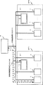
- FIG. 1 is an overall configuration diagram showing the overall configuration of the cash processing system according to the first embodiment.
- a cash processing system 9 includes a server 2 and a plurality of cash processing devices 1.
- a plurality of cash processing apparatuses 1 are installed in each branch GP1 and GP2 of a financial institution, and each cash processing apparatus 1 in each branch GP1 and GP2 can exchange information with a server 2. Is illustrated.
- each branch GP1, GP2 in the vicinity where a plurality of cash processing apparatuses 1 are installed, an electronic bulletin board 31 is installed to inform the customer of the state of each cash processing apparatus 1.
- an electronic bulletin board 31 is installed to inform the customer of the state of each cash processing apparatus 1.
- branches GP1 and GP2 are shown for ease of explanation, but the number of branches managed by the server 2 is not limited.
- 3rd display part 31 displays the whole state of a plurality of cash processing devices 1, and can apply a liquid crystal display, a segment display, an electronic bulletin board, etc.
- the third display unit 31 is connected to the server 2 and displays information received from the server 2. Further, the arrangement position of the third display unit 31 is not particularly limited, and is preferably a position that is easy for a customer who uses each cash processing apparatus 1 to see, for example, an area where the cash processing apparatus 1 is arranged. It may be hung from the ceiling or provided on the wall.
- Each cash processing apparatus 1 is a cash processing apparatus installed in each store GP1, GP2 of a financial institution. Each cash processing apparatus 1 can apply ATM which performs a deposit transaction, a withdrawal transaction, etc., for example. Each cash processing apparatus 1 can be applied to any of a deposit-only machine that performs only cash deposit, a deposit-only machine that performs only cash withdrawal, and a deposit / withdrawal machine that performs both cash deposit and withdrawal.
- the server 2 acquires various information from each cash processing apparatus 1 installed in each branch GP1, GP2 of the financial institution, and manages information related to each cash processing apparatus 2 based on the acquired information.
- the server 2 indicates the types of transactions that can be handled by each cash processing apparatus 1 according to the number of stored sheets stored in the banknote cassette of each cash processing apparatus 1, such as the third display unit 31 and the second. It can be displayed on the display unit 32. Thereby, about the transaction which a customer desires, a customer can be guided to the cash processing device which can be handled.
- FIG. 2 is a perspective view showing a main external configuration of the cash processing apparatus 1 according to the first embodiment.
- the cash processing apparatus 1 includes a banknote deposit / withdrawal slot 11, a card slot 12, a passbook slot 13, an operation display unit 33, and a second display unit 32.
- the operation display unit 33 may be a unit in which an operation unit and a display unit are physically integrated, such as a touch panel display, or an operation unit such as an operation button and a display.
- the display units may be physically different from each other.
- the operation display unit 33 is mainly used as an operation unit or a display unit for a customer to perform a transaction operation when the customer performs various transactions. That is, the operation display unit 33 displays a transaction type menu screen, displays various transaction input screens, and displays transaction results in order to proceed with various transaction procedures selected by the customer.
- the display part contained in the operation display part 33 is mainly utilized by the transaction procedure with respect to the 2nd display part 33 mentioned later, it can be considered to be a 1st display part.
- the second display unit 32 displays auxiliary information for the customer, and functions as an auxiliary display or an individual display for the operation display unit 33 mainly used for transaction operations.
- the arrangement position of the 2nd display part 32 is not specifically limited, When the customer who uses the cash processing apparatus 1 stands in front of the cash processing apparatus 1, it is desirable to be provided in the position where a customer is easy to see. .
- FIG. 2 the case where the 2nd display part 32 is displayed on the upper part of the cash processing apparatus 1 is illustrated.
- the banknote deposit / withdrawal port 11 transports banknotes inserted by a customer one by one to a transport path (not shown) inside the cash processing apparatus 1 or withdraws from the transport path inside the cash processing apparatus 1.
- the banknote which concerns on is discharged.
- the card entry / exit 12 takes the inserted card into the cash processing apparatus 1 or discharges the card conveyed from the cash processing apparatus 1.
- the bankbook entry / exit 13 takes the inserted bankbook into the cash processing apparatus 1 and discharges the bankbook transported from the cash processing apparatus 1.
- FIG. 3 is a configuration diagram showing the configuration of the control system of the cash processing apparatus 1 according to the first embodiment.
- the cash processing apparatus 1 includes a control unit 10, a storage unit 14, a communication unit 15, a banknote recognition unit 17, an operation display unit 33, a second display unit 32, and a plurality (five in FIG. 3) of banknote cassettes 18A. With ⁇ 18E.
- the banknote cassettes 18A to 18E are mounted as lower units of the cash processing apparatus 1 and store banknotes for each denomination.
- the banknote recognition unit 17 identifies the denomination of the banknote inserted from the banknote deposit / withdrawal port 11 and the banknote is accumulated in the banknote cassette 18 of the corresponding denomination.
- the banknotes fed out from the corresponding denomination banknote cassette 18 are discharged from the banknote deposit / withdrawal port 11.
- Each banknote cassette 18 may be, for example, dedicated to depositing and dispensing, or may be a deposit / withdrawal type that uses the deposited banknote as a withdrawal banknote (that is, a reflux recycling cassette). good. In this embodiment, description will be made assuming a deposit / withdrawal banknote cassette.
- the banknote recognition unit 17 is mounted inside the cash processing apparatus 1 and identifies the denomination of the banknote to be deposited or withdrawn, counts the number of banknotes, and the state of the banknote (for example, fouling, tearing, True / false etc.). The determination result by the banknote recognition unit 17 is notified to the control unit 10.
- the control unit 10 is responsible for various functions that can be executed by the cash processing apparatus 1. For example, the control unit 10 controls various transaction processes of the cash processing apparatus 1, manages the banknote storage status (that is, the number of stored banknotes) of the banknote cassette 18, or determines itself according to the banknote cassette 18 storage status. The type of transaction that can be implemented in is displayed, or the customer is guided to carry out with another cash processing device as necessary.
- the control unit 10 controls various transaction processes of the cash processing apparatus 1, manages the banknote storage status (that is, the number of stored banknotes) of the banknote cassette 18, or determines itself according to the banknote cassette 18 storage status.
- the type of transaction that can be implemented in is displayed, or the customer is guided to carry out with another cash processing device as necessary.
- control part 20 implement
- Various functions may be constructed by installing the processing program.
- the processing program can be shown as a functional block illustrated in FIG.
- the control unit 10 includes a transaction processing unit 101, a cassette state management unit 102, a setting unit 103, and a customer guidance display control unit 104 as shown in FIG.
- the transaction processing unit 101 processes various transactions such as a deposit transaction and a withdrawal transaction in the cash processing apparatus 1.
- Transaction processing unit 101 performs the type of transaction processing instructed through operation display unit 33 of cash processing apparatus 1.
- the cassette state management unit 102 manages the storage status stored in each of the banknote cassettes 18 (18A, 18B, 18C, 18D, 18E).
- the cassette state management unit 102 recognizes the denomination information of banknotes stored in each banknote cassette 18 in advance, and manages the number of banknotes stored in each banknote cassette 18 for each banknote cassette. For example, the cassette state management unit 102 manages the storage status of each banknote cassette 18 based on sensor information from a full sensor, a near full sensor, an end sensor, a near-and-sensor, and the like provided in each banknote cassette 18. Alternatively, for example, the number of stored bill cassettes 18 when the power is turned on is held, and addition / subtraction processing is performed using the number of deposits or withdrawals counted by the bill recognition unit 17 in subsequent transaction processing. You may make it manage the storage condition of each banknote cassette 18. FIG.
- full is a state in which banknotes are stored to the full capacity in the banknote cassette and no more banknotes can be stored
- near full is a state that is not full but close to full
- an end is a banknote in the banknote cassette.
- a state where there is no end, a near end refers to a state close to the end although there is no bill.
- the setting unit 103 sets various setting information related to customer guidance display processing by a customer guidance display control unit 104 to be described later.
- the setting unit 103 sets various kinds of setting information related to the control of customer guidance display. More specifically, the setting unit 103 can set setting information including a threshold value (hereinafter referred to as a customer guidance threshold value) to be compared with the number of stored bill cassettes 18 related to customer guidance display control.
- a threshold value hereinafter referred to as a customer guidance threshold value
- the customer guidance threshold value is a threshold value set for each deposit transaction or withdrawal transaction for suppressing the execution of the transaction.
- the customer guidance threshold is a value relating to the number of stored sheets set in each banknote unit 18 for executing display control for urging the customer to use the other cash processing apparatus 1 while avoiding cash collection or cash loading by an attendant. is there.
- the banknote cassette 18 of the other cash processing apparatus 1 installed in the same branch GP1 or GP2 may not be in a full state or an end state. Therefore, in order to start the customer guidance that prompts the customer to use the other cash processing device 1 in order to level the operation of all the cash processing devices 1 in the branch and reduce the number of dispatches to each branch, A customer guidance threshold is set for each bill cassette 18.
- the customer guidance threshold value is, for example, a value close to the near full value for detecting the near full state of the banknote cassette 18 and a value smaller than the near full value, or a value close to the near end value for detecting the near end state and greater than the near end value. A large value is desirable.
- the customer guidance threshold is a threshold for the purpose of guiding a customer to another cash processing apparatus 1 in a branch. That is, the deposit transaction or withdrawal transaction in the cash processing apparatus 1 is possible.
- a customer guidance threshold is provided in order to start a customer guidance display for guiding the customer to another cash processing apparatus 1 of the branch.
- the cash processing apparatus 1 even if the banknote cassette 18 that is reflux-type recycling temporarily stores a number of banknotes exceeding the customer guidance threshold value, the banknotes are removed from the banknote cassette 18 in subsequent withdrawal transactions. In some cases, the number of stored bill cassettes 18 is reduced. In such a case, the cash processing apparatus 1 can of course perform a withdrawal transaction, and can perform a deposit transaction because the number of stored bill cassettes 18 has decreased. By performing such operation, it is possible to level the operation of the cash processing apparatus 1 in the branch and reduce the number of dispatches of the staff.
- the value of the customer guidance threshold is a value smaller than the near full value for detecting the near full state of the banknote cassette 18 or a value larger than the near end value for detecting the near end state.
- the customer guidance threshold value may be a value common to all of the plurality of cash processing apparatuses 1 in the branch, or may be a value different for each cash processing apparatus 1. Further, the customer guidance threshold value may be a value common to all of the plurality of banknote cassettes 18 or may be a value different for each banknote cassette 18. Depending on the model of the cash processing apparatus 1, the maximum number of banknote cassettes 1 may be different. Therefore, you may enable it to set according to the model etc. of the cash processing apparatus 1.
- the customer guidance threshold value may be set to a plurality of values for one banknote cassette 18.
- a plurality of threshold values such as a first threshold value and a second threshold value are provided as customer guidance threshold values, and a different customer guidance display screen is displayed each time the number of stored bill cassettes 18 reaches each threshold value. May be.
- the customer guidance display control unit 104 compares the number of stored bill cassettes 18 managed by the cassette state management unit 102 with the customer guidance threshold value, and depending on the comparison result, the customer guidance display control unit 104 sends information to other cash processing apparatuses 1. Control the display of the customer guidance display screen that prompts the customer to use.
- the detailed processing of the customer guidance display control unit 104 will be described in the operation section, but the customer guidance display control unit 104 may display a customer guidance display screen on the second display unit 32, A customer guidance display screen may be displayed on the operation display unit 33, or a customer guidance display screen may be displayed on both the second display unit 32 and the operation display unit 33.
- the operation of the entire cash processing apparatus 1 installed at the branch can be leveled.
- the dispatch of a staff member of the police company is performed when one cash processing device 1 is in a full state or an end state, so that the number of uses of the cash processing device 1 that is likely to be in a full state or an end state is reduced.
- the number of dispatches of the clerk can be reduced.
- storage part 14 memorize
- the information regarding banknote storage of the banknote cassette 18 includes, for example, setting information regarding the denomination of banknotes stored in each banknote cassette 18, the number of stored banknote cassettes 18, status information of each banknote cassette 18 (for example, full state, near full) State, end state, near end state, customer induction state, etc.).
- the setting information related to customer guidance display control is information including a customer guidance threshold value, screen information related to customer guidance display, and the like.
- the communication unit 15 performs information transmission / reception processing with the server 2.
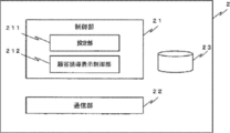
- FIG. 4 is an internal configuration diagram showing an internal configuration of the server 2 according to the first embodiment.
- the server 2 includes a control unit 21, a communication unit 22, and a storage unit 23.
- the server 2 has the same hardware configuration as an existing server computer.
- the server 2 acquires various information from each cash processing apparatus 1 installed in each branch GP1, GP2, and manages the state of each cash processing apparatus 1 in each branch GP1, GP2.
- the server 2 acquires information regarding the storage status of each banknote cassette 18 from each cash processing apparatus 1 of each branch GP1, GP2, and other information about each branch according to the storage status of each banknote cassette 18 of each cash processing apparatus 1.
- the customer guidance display screen that prompts the customer to use the cash processing apparatus 1 is controlled.
- the control unit 21 includes a setting unit 211 and a customer guidance display control unit 212.
- the setting unit 211 and the customer guidance display control unit 212 are basically functional units that are the same as or correspond to the setting unit 103 and the customer guidance display control unit 104 included in the control unit 10 of each cash processing apparatus 1.
- the control unit 21 can control the display screen displayed on the operation display unit 33, the second display unit 32, and the third display unit 31 of each cash processing apparatus 1.
- control unit 21 can instruct each cash processing apparatus 1 to display the customer guidance display screen on the second display unit 32 or display the customer guidance display screen on the operation display unit 33. Moreover, the control part 21 can also display a customer guidance display screen on the 3rd display part 31 provided in the area where the cash processing apparatus 1 of branch GP1 and GP2 is installed.
- the storage unit 23 is a processing program executed by the control unit 21, information on banknote storage of each banknote cassette 18 of each cash processing apparatus 1 of each branch GP1, GP2, setting information related to customer guidance display control, transaction information, transaction The information acquired at the time of storage is stored.
- the information regarding the banknote storage of the banknote cassette 18 is the setting information regarding the money type of a banknote stored in each banknote cassette 18, each banknote cassette 18, the number of storage of each banknote cassette 18, for each cash processing apparatus of each branch, for example.
- There is status information for example, full state, near full state, end state, near end state, customer guidance state, etc.
- the setting information related to customer guidance display control is information including a customer guidance threshold value, screen information related to customer guidance display, and the like.
- the communication unit 22 performs information transmission / reception processing between each cash processing apparatus 1 and the third display unit 31 of each branch.
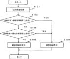
- FIG. 5 is a flowchart showing the operation of the customer guidance display process according to the first embodiment.
- the customer guidance display screen can be displayed on each or all of the third display unit 31 of each branch, the second display unit 32 of each cash processing device 1, and the operation display unit 31 of each cash processing device 1. Moreover, you may make it the instruction
- FIG. 1 A block diagram illustrating an exemplary computing environment in accordance with the present disclosure.
- control unit 10 of each cash processing apparatus 1 displays a customer guidance display screen on the second display unit 32 .
- the setting unit 104 has a customer guidance threshold set for each banknote cassette 18.
- the customer guidance threshold value is smaller than the near full value for detecting that the number of stored bill cassettes 18 is increased (customer guidance threshold for deposit), and the number of stored bill cassettes 18 is small.
- a value larger than the near-end value for detecting this (customer guidance threshold for withdrawal) is set.
- the control unit 10 of the cash processing apparatus 1 monitors the number of stored bill cassettes 18 for each bill cassette 18 (S101).
- the customer guidance display control unit 104 compares the number of stored bill cassettes 18 with the customer guidance threshold (for deposit) (S102).
- the customer guidance display control unit 104 performs the processing after S102 at the time of first transition to the transaction screen, such as at the time of activation, and when the respective transactions are completed. Moreover, the customer guidance display control part 104 may perform the process after S102, for example at the time of shifting to the transaction screen for the first time or when each transaction is completed. That is, the storage status of each banknote cassette 18 changes when the transaction such as the previous transaction or the main transaction is completed. Therefore, each time a transaction is completed, the number of stored bill cassettes 18 is compared with the customer guidance threshold value. Further, the customer guidance display control unit 104 compares the number of stored sheets and the customer guidance threshold value (for deposit) for each of the plurality of banknote cassettes 18A to 18E.
- the customer guidance display control unit 104 displays a customer guidance display screen on the second display unit 32 and the operation display unit 33 (S104). ).
- the customer guidance display control unit 104 compares the number of stored bill cassettes 18 with the customer guidance threshold (for withdrawal) (S103). At this time, the customer guidance display control unit 104 compares the number of stored sheets and the customer guidance threshold (for withdrawal) for each of the plurality of banknote cassettes 18A to 18E.
- the customer guidance display control unit 104 displays the customer guidance display screen on the second display unit 32 and the operation display unit 33. Is displayed (S104).
- the customer guidance display control unit 104 displays the customer guidance display screen. Is not displayed (S105).
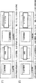
- FIG. 6 is an explanatory diagram for explaining a display method of the customer guidance display screen according to the first embodiment.
- the customer guidance display control unit 104 displays a message screen including, for example, “accepting only deposit”. Displayed on the second display section 32.
- the customer who wants the withdrawal transaction can be guided to the other cash processing apparatus 1 by notifying the customer of the message “receiving only deposit”.
- the customer guidance display control unit 104 when the number of stored bill cassettes 18 falls below the customer guidance threshold for withdrawal, the customer guidance display control unit 104, for example, “Only accepting deposits, withdrawals being restricted” Is displayed on the second display section 32.
- the customer can be guided to another cash processing apparatus 1 by clarifying the type of transaction to be suppressed by informing the customer of the message “withdrawal is being restricted”.
- the customer guidance display control unit 104 uses large characters such as “accepting only deposit”. A screen including the displayed message and a message displayed with a small character such as “withdrawal being restricted” is displayed on the second display unit 32.
- the type of transaction "withdrawal transaction" to be suppressed by the cash processing apparatus 1 is displayed small, and the customer is guided.
- the cash processing apparatus 1 is in a state where it can perform a withdrawal transaction or a deposit transaction because the number of stored sheets has reached the customer induction threshold but is not in an end state or a full state.
- the banknote cassette 18 is stored in a small number or stored in a large number.
- the cash processing apparatus 1 informs the customer that only the deposit transaction or the withdrawal transaction can be accepted. Thereby, the customer who desires a withdrawal transaction or a deposit transaction can be guided to the other cash processing apparatus 1.
- banknote cassette 18 has a recirculation type recycling function
- a deposit transaction after the customer guidance threshold for withdrawal is reached and the number of stored banknote cassettes 18 increases, a customer guidance display screen is displayed. Will be hidden and withdrawal transactions will be accepted again.
- the customer guidance display screen is displayed on the second display unit 32
- the customer guidance display screen may be displayed on the operation display unit 33.
- the display screen before the transaction is displayed on the display screen before the transaction is executed as shown in FIG.
- the customer guidance display screen illustrated in FIG. 6 (3) may be displayed as a pop-up screen.
- 12 and 13 are explanatory diagrams for explaining a customer guidance display screen displayed on the third display unit 31 according to the first embodiment.
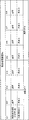
- the customer guidance display screen illustrated in FIG. 12 displays, for each cash processing apparatus 1, whether a deposit transaction, a withdrawal transaction is being accepted or restricted in a tabular format.
- the customer guidance display screen illustrated in FIG. 13 displays “ ⁇ ” when the deposit transaction or withdrawal transaction is being accepted, and “ ⁇ ” when the transaction is being restricted. It should be noted that “ ⁇ ” during restriction is that, as described above, even when the number of stored cash processing apparatus 1 has reached the customer induction threshold, the deposit transaction or the withdrawal transaction itself is possible. “ ⁇ ” instead of “ ⁇ ”.
- the second embodiment also illustrates a case where the present invention is applied to a cash processing apparatus represented by an ATM provided in a financial institution or the like and a server that monitors the cash processing apparatus and the like.
- the second embodiment is characterized in that the customer is guided according to the overall storage status of the plurality of cash processing apparatuses 1 installed in the branch.
- FIG. 7 is an explanatory diagram for explaining the overall operation of the customer guidance display process according to the second embodiment.
- FIG. 8 is a flowchart showing the operation of the customer guidance display process in the server 2 according to the second embodiment.
- the server 2 constantly monitors the storage information of each banknote cassette 18 for each of all the cash processing apparatuses 1. For example, the server 2 transmits a request signal for inquiring the number of stored bill cassettes 18 to each cash processing apparatus 1 that is performing the transaction. Each cash processing apparatus 1 returns the number of stored bill cassettes 18 in response to an inquiry from the server 2. In this way, the server 2 acquires the number of stored bill cassettes 18 from each of all the cash processing apparatuses 1 (S201).
- the server 2 manages the storage status of the cash processing apparatuses 1 of each group.
- numbers such as “01” are identification numbers of the cash processing apparatus 1.
- “Normal” or “exceeding customer guidance threshold (for deposit)” indicates the storage status of each cash processing apparatus 1. For example, “customer induction threshold (for deposit) exceeding” is “01”. This indicates that the number of stored items 1 exceeds the customer guidance threshold (for deposit), indicating that it is operating “normally”.
- the storage status may be managed as “near full state”, “full state”, “near end state”, “end state”, or the like.
- “payment suppression display”, “non-display”, and the like indicate whether the customer guidance information display screen is displayed on the display unit (second display unit 32, operation display unit 33, etc.) of the cash processing apparatus 1. It shows. For example, “payment suppression display” indicates that a customer guidance display screen for suppressing payment is displayed.
- the customer guidance display control unit 202 refers to a predetermined bias condition for each group, and the storage number is biased based on the storage status of all the cash processing apparatuses 1 in the group. It is determined whether or not (S202).
- the group is a group that can guide a customer to another cash processing apparatus 1 when the number of stored cash handling apparatuses 1 reaches a customer induction threshold, and for example, a branch of a financial institution is used. it can.
- the bias condition is a condition for determining whether or not there is a bias in the number of stored sheets of all the cash processing apparatuses 1 belonging to the same group.
- FIGS. 10 and 11 are explanatory diagrams for explaining the bias condition according to the second embodiment. Here, a case where four cash processing apparatuses 1 form one group is illustrated.
- the number of sheets stored in two cash processing devices 1 in one group has reached a customer guidance threshold for depositing (indicated as “threshold for deposit” in FIG. 10). This is a case where the number of sheets stored in one cash processing apparatus 1 has reached the customer guidance threshold for withdrawal (indicated as “threshold for withdrawal” in FIG. 10).
- the customer guidance display control unit 202 determines that it is “biased” (S203). A customer guidance display screen is displayed on the cash processing apparatus 1 (with the stored number reaching the customer guidance threshold) (S204).
- FIG. 10 (2) shows a case where the number of sheets stored in the three cash processing apparatuses 1 in one group has reached the customer guidance threshold for deposit (“the threshold for deposit”).
- FIG. 10 (3) shows a case where the number of stored three cash processing apparatuses 1 in one group has reached the customer guidance threshold for withdrawal (“threshold for withdrawal”).
- the customer guidance display control unit 202 determines with "it is not biased" (S203), and does not display a customer guidance display screen (S205).
- the customer guidance display screen is not displayed and the stored number of any cash processing apparatus 1 is full.
- cash collection or cash loading is performed.
- cash collection or cash loading can be performed simultaneously for a plurality of cash processing apparatuses 1, so cash collection or cash loading Can be performed efficiently.
- one of the four cash processing devices 1 is out of service, and another cash processing device 1 is out of service ( Out of Service).
- the customer guidance display control unit 202 determines that each of the normally operating cash processing apparatuses is in a different state (that is, the number of stored sheets has reached the deposit threshold and the withdrawal threshold. If there is a mixture of what has been reached), it is determined that it is biased (S203), and a customer guidance display screen is displayed (S204).
- the customer guidance display control unit 202 indicates that all of the cash processing devices that are operating normally are in the same state (that is, all the cash processing devices 1 have reached the deposit threshold or the withdrawal threshold). Is determined to be biased (S203), the customer guidance display screen is not displayed (S205).
- customer guidance display screens displayed on the second display unit 32 and the operation display unit 33 of each cash processing apparatus 1 by the server 2 are the same as those in the first embodiment, as shown in FIGS. ) Is displayed.
- the third embodiment also illustrates a case where the present invention is applied to a cash processing apparatus represented by an ATM provided in a financial institution or the like and a server that monitors the cash processing apparatus.
- FIG. 14 is a configuration diagram showing the configuration of the control system of the cash processing apparatus 1A according to the third embodiment.
- the cash processing apparatus 1A includes a control unit 10, a storage unit 14, a communication unit 15, a banknote recognition unit 17, an operation display unit 33, a second display unit 32, and a plurality (in FIG. 14). 4) banknote cassettes 18A to 18D, a deposit-only banknote cassette 51, and a reject box 52.
- the cash processing apparatus 1A has a deposit-dedicated banknote cassette 51 and a reject box 52 in addition to the banknote cassettes 18A to 18D which are reflux-type recycling cassettes.
- the deposit-only banknote cassette 51 is a banknote cassette that only collects banknotes and does not withdraw banknotes stored.
- the deposit-only banknote cassette 51 has a function of collecting banknotes, but has a function of feeding out the banknotes stored in order to withdraw the deposited banknotes again like a reflux recycling cassette. Not done.
- the deposit-dedicated banknote cassette 51 generally has no denomination restrictions on banknotes to be stacked, and can stack banknotes of a plurality of denominations.
- An example of how to use the deposit-only banknote cassette 51 is, for example, when the number of stored recirculation-type recycling cassettes increases and the recycling-type recycling cassette becomes full (or near-full) and cannot be used. It is conveyed and accumulated in the deposit-only banknote cassette 51. Further, for example, when the denomination of the deposited banknote is not set in each reflux type recycling cassette, the deposited banknote is conveyed to the deposit dedicated banknote cassette 51 and accumulated.
- the deposited banknotes 51 are deposited. Can be accumulated.
- the reject store 52 holds the rejected banknote based on the discrimination result by the banknote recognition unit 17. For example, when the deposited banknote is dirty or torn due to the discrimination result by the banknote recognition unit 17 and cannot be used as a banknote to be withdrawn, the reject bank 52 holds the banknote in the reject bank 52 (for operation) Accordingly, banknotes with dirt or tears may be accumulated in the banknote cassette 51 for depositing. In addition, for example, when it is determined that the bill is a fake bill by the bill recognition unit 17, the bill that has been determined to be a fake bill is returned to the customer, but the bill that has been withdrawn from the reflux recycling cassette is rejected 52. Is on hold.
- banknotes are collected such as the deposit-only banknote cassette 51, reject box 52, etc., but the banknotes stored therein are not used for withdrawal. Call.
- the cash processing apparatus 1A may have only the deposit-only banknote cassette 51 or only the reject box 52. That is, 1 A of cash processing apparatuses may have only one non-withdrawal storage part.
- the cash processing apparatus 1A may have a plurality of deposit-dedicated banknote cassettes 51 or a plurality of reject boxes 52. That is, 1 A of cash processing apparatuses may have a some non-withdrawal storage part about each of the non-withdrawal storage part of the type from which a function and a use differ, respectively.
- the cash processing apparatus 1A differs from the first embodiment in the processing of the customer guidance display control unit 104A. Therefore, in the third embodiment, the processing of the customer guidance display control unit 104A will be described in detail. Since the processing of the other components is the same as that of the first embodiment, detailed description thereof is omitted here.
- the customer guidance display control unit 104A controls the other cash processing apparatuses 1 according to the storage status of each of the banknote cassettes 18A to 18D, the deposit dedicated banknote cassette 51, and the reject storage 52 managed by the cassette state management unit 102. Control the display of the customer guidance display screen that prompts the customer to use.
- the cassette state management unit 102 manages the number of stored bill-only banknote cassettes 51 and reject boxes 52 as non-withdrawal storage units.
- the cash processing apparatus 1A can no longer perform a deposit transaction, and when the number of sheets stored in the reject store 52 is in a full state, The cash processing apparatus 1A cannot perform a deposit transaction or a withdrawal transaction. In these cases as well, a staff member of the police company is dispatched to collect cash.
- the cash processing apparatus 1A is limited for deposit transactions, but basically can perform deposit transactions.
- the cash processing apparatus 1A can perform a withdrawal transaction. Therefore, if a withdrawal transaction is performed and the number of stored bill cassettes 18A to 18D in a nearly full state is reduced, the cash processing apparatus 1A can perform a deposit transaction and a withdrawal transaction without restriction.
- the cash processing apparatus 1A will perform the deposit transaction and the withdrawal transaction if the staff of the police company does not dispatch for cash collection. It is not in a state that can be performed.
- the customer can be guided to use the other cash processing apparatus 1A before the deposit-only banknote cassette 51 and the reject storage 52 are full.
- the operation of the entire cash processing apparatus 1 installed in the branch can be leveled.
- the number of dispatches of the clerk can be reduced.
- the customer guidance display screen includes the third display unit 31 of each branch, the second display unit 32 of each cash processing device 1A, and the operation display unit 31 of each cash processing device 1, respectively. Or you can display it all. Moreover, you may make it the instruction
- control unit 10 of each cash processing apparatus 1A displays a customer guidance display screen on the second display unit 32 .
- FIG. 15 is a flowchart showing the operation of the customer guidance display process according to the third embodiment.
- the setting unit 104 sets a customer guidance threshold value for each of the banknote cassettes 18A to 18D, the deposit-only banknote cassette 51 as the non-withdrawal storage unit, and the reject box 52. ing.
- the customer guidance threshold values for the deposit-only banknote cassette 51 and the reject store 52 are represented as customer guidance threshold values (for non-withdrawal).
- the number of banknotes existing in the cassette at the time of execution is expressed as the number of stored sheets.
- the control unit 10 of the cash processing apparatus 1 monitors the number of stored bill cassettes 18 for each bill cassette 18 (S101).
- the customer guidance display control unit 104 compares the number of stored bill cassettes 18 with the customer guidance threshold (for deposit) (S102).
- the customer guidance threshold for deposit
- the customer guidance display control unit 104A confirms the number of stored bill-only bill cassettes 51 and reject box 52 (see FIG. S301).
- the customer guidance display control unit 104A displays the customer guidance on the second display unit 32 and the operation display unit 33. A display screen is displayed (S104).
- the number of stored bill cassettes 18A to 18D is reduced by the withdrawal transaction, and then the normal deposit transaction becomes possible. Further, before the deposit-only banknote cassette 51 and the reject storage 52 are full, the customer can be guided to use the other cash processing apparatus 1A.
- FIG. 16 is a flowchart showing the operation of the customer guidance display process according to the third embodiment.
- the setting unit 104 sets a customer guidance threshold value for each of the banknote cassettes 18A to 18D, the deposit-only banknote cassette 51 as the non-withdrawal storage unit, and the reject box 52. ing.
- the control unit 10 of the cash processing apparatus 1 monitors the number of stored bill cassettes 18 for each bill cassette 18 (S101).
- the customer guidance display control unit 104 determines whether or not the storage state of each banknote cassette 18 that is a reflux type recycling cassette is in a full state (or near full state) (S401).
- each banknote cassette 18 that is a reflux-type recycling cassette When the storage status of each banknote cassette 18 that is a reflux-type recycling cassette is not full (or near-full), the customer guidance display control unit 104 determines that the storage status of each banknote cassette 18 that is a reflux-type recycling cassette is in an end state (or It is determined whether or not it is in the near end state (S402).
- the process returns to S101.
- each banknote cassette 18 that is a reflux type recycling cassette When the storage state of each banknote cassette 18 that is a reflux type recycling cassette is full (or near full), or the storage state of each banknote cassette 18 that is a reflux type recycling cassette is in an end state (or near end state).
- the customer guidance display control unit 104A confirms the number of stored deposit-only banknote cassettes 51 and the reject storage 52 (S403).
- the customer guidance display control unit 104A displays the customer guidance on the second display unit 32 and the operation display unit 33. A display screen is displayed (S104).
- the customer guidance display control unit 104A displays the second display unit 32 and the operation display unit 33 as follows.
- the customer guidance display screen is not displayed (S105).
- FIG. 17 is a flowchart showing an operation of customer guidance display processing according to the third embodiment.
- the setting unit 104 sets a customer guidance threshold value for each of the banknote cassettes 18A to 18D, the deposit-only banknote cassette 51 as the non-withdrawal storage unit, and the reject box 52. ing.
- the control unit 10 of the cash processing apparatus 1 monitors the number of stored bill cassettes 18 for each bill cassette 18 (S101).
- the customer guidance display control unit 104 confirms the number of sheets stored in the deposit-dedicated banknote cassette 51 and the reject store 52, which are non-withdrawal storage units (S401).
- the customer guidance display control unit 104A displays the customer guidance on the second display unit 32 and the operation display unit 33. A display screen is displayed (S104).
- the customer guidance display control unit 104A displays the second display unit 32 and the operation display unit 33 as follows.
- the customer guidance display screen is not displayed (S105).
- the operation process shown in FIG. 17 is a deposit-only bill even when the number of stored bill cassettes 18A to 18D, which are reflux-type recycling cassettes, is not in a full state (or near full state) or a state in which the customer guidance threshold is reached. Before the number of sheets stored in the cassette 51 and the reject box 52 becomes full, the customer can be guided to use the other cash processing apparatus 1A.
- control unit 10 of each cash processing apparatus 1 and the control unit 21 of the server 2 also manage the storage status of each banknote cassette of the cash processing apparatus 1. Therefore, when the stored number of only 10,000 yen banknotes reaches the customer induction threshold among a plurality of banknote cassettes, for example, “10,000 yen deposit transaction (or withdrawal transaction) is being restricted” Moreover, you may make it display the customer guidance display screen which suppresses transaction for every denomination.
- the setting unit 103 and the setting unit 201 may be manually set by a maintenance person such as a financial institution.
- the setting unit 103 and the setting unit 201 may set a value derived from statistical data or analysis data of fluctuation data of the number of stored bill cassettes of each cash processing apparatus 1 in the past as a customer guidance threshold value. . More specifically, the usage frequency of the cash processing apparatus 1 varies depending on weekdays and holidays. Accordingly, it may be possible to set a value in consideration of the usage frequency based on a temporal factor.
Landscapes
- Physics & Mathematics (AREA)
- General Physics & Mathematics (AREA)
- Business, Economics & Management (AREA)
- Accounting & Taxation (AREA)
- Finance (AREA)
- Financial Or Insurance-Related Operations Such As Payment And Settlement (AREA)
Abstract
本発明に係る現金処理装置は、紙幣を収納する複数の紙幣収納部と、各紙幣収納部内の収納状況を管理する収納状況管理部と、各紙幣収納部内の収納状況に応じて、複数種類の取引のうち、特定の取引を抑制し、及び又は、特定の取引以外の取引を促成する表示画面を表示する表示制御部とを備えることを特徴とする。
Description
本発明は、現金処理装置及びサーバに関し、例えば、金融機関等に配置されている現金処理装置及びサーバに適用し得るものである。
例えば、金融機関等の店舗には、自動取引装置(ATM:Automatic Teller Machine)に代表される現金処理装置がある。
現金処理装置は、金種毎の紙幣を収納する紙幣カセットが搭載されており、入金取引の場合、投入された紙幣は紙幣カセットに収納され、出金取引の場合、紙幣カセットに収納されている紙幣が繰り出される。
例えば、紙幣カセットに設けられているフルセンサがフル状態を検知した場合、紙幣カセットから紙幣を回収するために、警送会社等にアラームが通知され、金融機関等に係員が出動し、係員が紙幣カセットから紙幣を回収する。また例えば、紙幣カセットのエンドセンサが空状態を検知した場合も同様に、紙幣カセットに紙幣を装填するために、警送会社等にアラームが通知され、係員が紙幣カセットに紙幣を装填する。
特開2000-339516号公報、特開平11-25352号公報には、フル状態又はエンド状態の現金処理装置において、入金処理又は出金処理を縮退して、顧客を他の現金処理装置に誘導することが開示されている。
例えば金融機関等の店舗に複数台の現金処理装置がある場合でも、いずれかの現金処理装置がフル状態又はエンド状態となったときに、紙幣回収又は紙幣装填のため、警送会社等の係員が出動している。
しかしながら、店舗において、現金処理装置の設置場所や機種等により、特定の現金処理装置に取引が集中することがある。例えば、店舗の出入口付近にある現金処理装置は多く利用される傾向にあるが、出入口から離れた位置の現金処理装置の利用は少ない場合がある。
そうすると、他の現金処理装置は取引が可能であるにもかかわらず、取引の集中している特定の現金処理装置のみがフル状態又はエンド状態となり、係員が出動することになる。その結果、係員の出動回数が無駄に多くなってしまうという問題が生じ得る。
そのため、複数の現金処理装置全体の稼働の平準化を図り、係員の出動回数を減らすため、フル状態又はエンド状態となる前に、一時的に入金取引又は出金取引を抑制することを表示ができ、他の現金処理装置に顧客を誘導できる現金処理装置及び現金処理システムが求められている。
かかる課題を解決するために、第1の本発明に係る現金処理装置は、(1)紙幣を収納する複数の紙幣収納部と、(2)各紙幣収納部内の収納状況を管理する収納状況管理部と、(3)各紙幣収納部内の収納状況に応じて、複数種類の取引のうち、特定の取引を抑制し、及び又は、特定の取引以外の取引を促成する表示画面を表示する表示制御部とを備えることを特徴とする。
第2の本発明に係るサーバは、複数の紙幣収納部を有する複数の現金処理装置のそれぞれの収納状況を管理するサーバにおいて、(1)各現金処理装置から取得した各紙幣収納部の収納状況を管理する収納状況管理部と、(2)各現金処理装置の各紙幣収納部内の収納状況に応じて、複数種類の取引のうち、特定の取引を抑制し、又は、特定の取引以外の取引を促成する表示画面を表示する表示制御部とを有することを特徴とする。
本発明によれば、複数の現金処理装置全体の稼働の平準化を図り、係員の出動回数を軽減するため、フル状態又はエンド状態となる前に、一時的に入金取引又は出金取引を抑制することを表示ができ、他の現金処理装置に顧客を誘導できる。
(A)第1の実施形態
以下では、本発明に係る現金処理装置及びサーバの第1の実施形態を、図面を参照しながら詳細に説明する。
以下では、本発明に係る現金処理装置及びサーバの第1の実施形態を、図面を参照しながら詳細に説明する。
第1の実施形態では、本発明を利用して、金融機関等に設けられているATMに代表される現金処理装置及び現金処理装置の監視等を行なうサーバに適用する場合を例示する。
(A-1)第1の実施形態の構成
図1は、第1の実施形態に係る現金処理システムの全体構成を示す全体構成図である。
図1は、第1の実施形態に係る現金処理システムの全体構成を示す全体構成図である。
図1において、第1の実施形態に係る現金処理システム9は、サーバ2と、複数の現金処理装置1とを有する。
図1では、金融機関の各支店GP1、GP2に複数の現金処理装置1が設置されており、各支店GP1、GP2の各現金処理装置1がサーバ2との間で情報交換できる現金処理システム9を例示している。
また、各支店GP1、GP2において、複数の現金処理装置1が設置されている付近には、各現金処理装置1の状態を顧客に知らせるために、電光掲示板31が設置されている。なお、この実施形態では、説明を容易にするために、2つの支店GP1、GP2のみを示しているが、サーバ2が管理する支店の数は限定されるものではない。
第3表示部31は、複数の現金処理装置1の全体の状態を表示するものであり、液晶ディスプレイ、セグメントディスプレイ、電子掲示板等を適用できる。第3表示部31は、サーバ2と接続されており、サーバ2から受信した情報を表示する。また、第3表示部31の配置位置は、特に限定されるものではなく、各現金処理装置1を利用する顧客が見やすい位置であることが望ましく、例えば、現金処理装置1が配置されているエリアの天井から吊り下げたり、壁面に設けたりしても良い。
各現金処理装置1は、金融機関の各店舗GP1、GP2に設置されている現金処理装置である。各現金処理装置1は、例えば、入金取引や出金取引などを行うATMを適用できる。各現金処理装置1は、現金の入金のみを行なう入金専用機、現金の出金のみを行なう出金専用機、現金の入金と出金の両方を行う入出金機のいずれにも適用できる。
サーバ2は、金融機関の各支店GP1、GP2に設置されている各現金処理装置1から各種情報を取得し、取得した情報に基づいて各現金処理装置2に関する情報を管理するものである。この実施形態では、サーバ2が、各現金処理装置1の紙幣カセットに収納されている収納枚数に応じて、各現金処理装置1で取り扱うことができる取引の種類を第3表示部31や第2表示部32に表示できるようにする。これにより、顧客が希望する取引については、取り扱い可能な現金処理装置に顧客を誘導できる。
図2は、第1の実施形態に係る現金処理装置1の主な外観構成を示す斜視図である。
図2に示すように、現金処理装置1は、紙幣入出金口11、カード入出口12、通帳入出口13、操作表示部33、第2表示部32を有する。
操作表示部33は、例えばタッチパネル式ディスプレイ等のように、操作部と表示部とが物理的に一体的になったものを適用しても良いし、また例えば操作ボタン等の操作部とディスプレイ等の表示部とがそれぞれ物理的に異なる構成であっても良い。操作表示部33は、顧客が各種取引を行う際に、顧客が取引操作を行う操作部又は表示部として主として利用するものである。つまり、操作表示部33は、取引種類のメニュー画面を表示したり、顧客に選択された各種取引の手続きを進行するため、各種取引の入力画面を表示したり、取引結果を表示したりする。なお、操作表示部33に含まれる表示部は、後述する第2表示部33に対して、取引手続きで主として利用されるため、第1表示部と考えることができる。
第2表示部32は、顧客に対して補助的な情報を表示するものであり、主として取引操作の利用に供される操作表示部33に対して補助的なディスプレイ又は個別のディスプレイとして機能する。第2表示部32の配置位置は、特に限定されるものではないが、現金処理装置1を利用する顧客が現金処理装置1の前に立ったときに、顧客が見やすい位置に設けられることが望ましい。なお、図2では、現金処理装置1の上部に第2表示部32が表示されている場合を例示している。
紙幣入出金口11は、顧客により投入された紙幣を、1枚ずつ現金処理装置1の内部の搬送路(図示しない)に紙幣を搬送したり、現金処理装置1の内部の搬送路から出金に係る紙幣を排出したりする。
カード入出口12は、挿入されたカードを現金処理装置1の内部に取り込んだり、現金処理装置1の内部から搬送されてきたカードを排出したりする。
通帳入出口13は、挿入された通帳を現金処理装置1の内部に取り込んだり、現金処理装置1の内部から搬送されてきた通帳を排出したりする。
図3は、第1の実施形態に係る現金処理装置1の制御系の構成を示す構成図である。
図3において、現金処理装置1は、制御部10、記憶部14、通信部15、紙幣認識部17、操作表示部33、第2表示部32、複数(図3では5個)の紙幣カセット18A~18Eを有する。
紙幣カセット18A~18Eは、現金処理装置1の下部ユニットとして搭載されているものであり、金種毎の紙幣を収納する。入金取引のときには、紙幣入出金口11から投入された紙幣の金種を紙幣認識部17が識別して、対応金種の紙幣カセット18に紙幣が集積される。出金取引のときには、対応金種の紙幣カセット18から繰り出された紙幣が紙幣入出金口11から排出される。各紙幣カセット18は、例えば、入金専用、出金専用のものであっても良いし、入金された紙幣を出金紙幣として利用する入出金対応型(つまり、還流型リサイクルカセット)であっても良い。この実施形態では、入出金対応型の紙幣カセットを想定して説明する。
紙幣認識部17は、現金処理装置1の内部に搭載されており、入金又は出金される紙幣の金種を識別したり、紙幣枚数を計数したり、紙幣の状態(例えば、汚損、破れ、真偽等)を判定する。紙幣認識部17による判定結果は、制御部10に通知される。
制御部10は、現金処理装置1が実行可能な各種機能を司るものである。例えば、制御部10は、現金処理装置1の各種取引処理を制御したり、紙幣カセット18の紙幣の収納状況(すなわち、収納枚数)を管理したり、紙幣カセット18の収納状況に応じて、自身で実施できる取引種類を表示したり、必要に応じて顧客を他の現金処理装置で実施することを誘導したりする。
なお、制御部20は、例えば、CPUが、ROMに格納される処理プログラムを実行することにより現金処理装置1ATM1の各種機能を実現する。処理プログラムがインストールされることで各種機能が構築されるようにしても良く、その場合、処理プログラムは図3に例示する機能ブロックとして示すことができる。
制御部10は、図3に示すように、取引処理部101、カセット状態管理部102、設定部103、顧客誘導表示制御部104を有する。
取引処理部101は、現金処理装置1における入金取引や出金取引等の各種取引の処理を行なうものである。取引処理部101は、現金処理装置1の操作表示部33を通じて指示された種別の取引処理を行なう。
カセット状態管理部102は、紙幣カセット18(18A、18B、18C、18D、18E)のそれぞれに収納されている収納状況を管理するものである。
カセット状態管理部102は、あらかじめ各紙幣カセット18に収納される紙幣の金種情報を認識しており、各紙幣カセット18の紙幣収納枚数を紙幣カセット毎に管理する。カセット状態管理部102は、例えば、各紙幣カセット18に設けられているフルセンサ、ニアフルセンサ、エンドセンサ、ニアアンドセンサ等からのセンサ情報に基づいて、各紙幣カセット18の収納状況を管理するようにしても良いし、又例えば、電源ON時の各紙幣カセット18の収納枚数を保持し、その後の取引処理で紙幣認識部17が計数した入金枚数又は出金枚数を用いて加算・減算処理を行なって各紙幣カセット18の収納状況を管理するようにしても良い。なお、例えば、フルとは紙幣カセット内に紙幣が容量いっぱいまで収納されこれ以上の紙幣を収納できない状態、ニアフルとは、容量いっぱいではないがフルに近い状態、エンドとは紙幣カセット内の紙幣が全く無い状態、ニアエンドとは紙幣が全く無いわけではないがエンドに近い状態を指す。
設定部103は、後述する顧客誘導表示制御部104による顧客誘導表示処理に係る各種設定情報の設定を行う。設定部103は、顧客誘導表示の制御に係る各種設定情報を設定する。より具体的には、設定部103は、顧客誘導表示制御に係る各紙幣カセット18の収納枚数と比較する閾値(以下、顧客誘導閾値と呼ぶ。)を含む設定情報を設定できる。
ここで、顧客誘導閾値は、入金取引又は出金取引毎に設定された、取引の実施を抑制するための閾値である。顧客誘導閾値は、係員による現金回収又は現金装填を回避して、他の現金処理装置1の利用を顧客に促すための表示制御を実行するための各紙幣ユニット18に設定する収納枚数に関する値である。
つまり、いずれかの紙幣カセット18がフル状態又はエンド状態になると、当該現金処理装置1の現金回収又は現金装填のために、係員が出動することになる。しかし、同じ支店GP1又はGP2に設置されている他の現金処理装置1の紙幣カセット18はフル状態又はエンド状態となっていないことがある。そこで、支店内の全ての現金処理装置1の稼働の平準化及び各支店への警送の出動回数を減らすために、他の現金処理装置1への利用を顧客に促す顧客誘導を開始するため、顧客誘導閾値を紙幣カセット18毎に設定する。
顧客誘導閾値は、例えば、紙幣カセット18のニアフル状態を検知するニアフル値に近い値であってニアフル値よりも小さい値、又は、ニアエンド状態を検知するニアエンド値に近い値であってニアエンド値よりも大きい値とすることが望ましい。
これは、顧客誘導閾値が、ニア状態(ニアフル状態)又はエンド状態(ニアエンド状態)を検知して、入金取引又は出金取引を縮退させるための閾値ではない。顧客誘導閾値は、支店にある他の現金処理装置1に顧客を誘導することを目的とするための閾値である。つまり、当該現金処理装置1での入金取引又は出金取引は可能である。警送の出動回数を減らすために、当該支店の他の現金処理装置1に顧客を誘導させる顧客誘導表示を開始するため、顧客誘導閾値を設けている。また、当該現金処理装置1において、還流型リサイクルである紙幣カセット18が顧客誘導閾値を超える枚数の紙幣が一時的に収納されていても、その後の出金取引で、紙幣カセット18から紙幣が出金され、当該紙幣カセット18の収納枚数が減ることもある。そのような場合には、当該現金処理装置1は、出金取引はもちろん可能であるし、紙幣カセット18の収納枚数が減ったため入金取引も可能となる。そのような運用を行なうことで、支店における現金処理装置1の稼働の平準化及び係員の出動回数を減らすことができる。
上記のような観点から、顧客誘導閾値の値は、紙幣カセット18のニアフル状態を検知するニアフル値よりも小さい値、又は、ニアエンド状態を検知するニアエンド値よりも大きい値とすることが望ましい。
また、顧客誘導閾値は、支店にある複数の現金処理装置1の全てに共通の値であっても良いし、現金処理装置1毎に異なる値であっても良い。さらに、顧客誘導閾値は、複数の紙幣カセット18の全てに共通する値であっても良いし、紙幣カセット18毎に異なる値であっても良い。これは、現金処理装置1の機種によっては、紙幣カセット1の最大収納枚数が異なることもある。そのため、現金処理装置1の機種等に応じて設定できるようにしても良い。
さらに、顧客誘導閾値の値は、1個の紙幣カセット18につき複数個の値を設定できるようにしても良い。例えば、顧客誘導閾値として、第1閾値、第2閾値等のように、複数個の閾値を設け、紙幣カセット18の収納枚数が各閾値に達するたびに、異なる顧客誘導表示画面を表示するようにしてもよい。
顧客誘導表示制御部104は、カセット状態管理部102により管理されている各紙幣カセット18の収納枚数と顧客誘導閾値とを比較して、その比較結果に応じて、他の現金処理装置1への利用を顧客に促す顧客誘導表示画面の表示制御を行なう。
顧客誘導表示制御部104の詳細な処理の説明については、動作の項で行なうが、顧客誘導表示制御部104は、第2表示部32に顧客誘導表示画面を表示するようにしても良いし、操作表示部33に顧客誘導表示画面を表示するようにしても良いし、第2表示部32と操作表示部33の両方に顧客誘導表示画面を表示するようにしても良い。
このように、他の現金処理装置1への利用を顧客に促すことで、支店に設置されている現金処理装置1全体の稼働を平準化できる。また、警送会社の係員の出動は、1個の現金処理装置1がフル状態又はエンド状態となったときに行われるところ、フル状態又はエンド状態となりそうな現金処理装置1の利用回数を減らし、他の現金処理装置1の稼働を高めることで、係員の出動回数を減らすことができる。
記憶部14は、制御部10により実行される処理プログラム、各紙幣カセット18の紙幣収納に関する情報、顧客誘導表示制御に係る設定情報、取引情報、取引の際に取得した情報等を記憶するものである。
なお、紙幣カセット18の紙幣収納に関する情報は、例えば、各紙幣カセット18に収納紙幣の金種に関する設定情報、各紙幣カセット18の収納枚数、各紙幣カセット18のステータス情報(例えば、フル状態、ニアフル状態、エンド状態、ニアエンド状態、顧客誘導状態等)等がある。また、顧客誘導表示制御に係る設定情報は、顧客誘導閾値、顧客誘導表示に係る画面情報等を含む情報である。
通信部15は、サーバ2との間で情報の送受信処理を行なうものである。
図4は、第1の実施形態に係るサーバ2の内部構成を示す内部構成図である。
図4において、第1の実施形態に係るサーバ2は、制御部21、通信部22、記憶部23を有する。
サーバ2は、既存のサーバコンピュータと同様のハードウエア構成を備える。サーバ2は、各支店GP1、GP2に設置されている各現金処理装置1から各種情報を取得し、各支店GP1、GP2の各現金処理装置1の状態を管理するものである。
サーバ2は、各支店GP1、GP2の各現金処理装置1から各紙幣カセット18の収納状況に関する情報を取得し、各現金処理装置1の各紙幣カセット18の収納状況に応じて、各支店の他の現金処理装置1への利用を顧客に促す顧客誘導表示画面を表示制御するものである。
制御部21は、設定部211、顧客誘導表示制御部212を有する。設定部211及び顧客誘導表示制御部212は、基本的には、各現金処理装置1の制御部10が有する設定部103及び顧客誘導表示制御部104と同一又は対応する機能部である。
制御部21は、各現金処理装置1の操作表示部33、第2表示部32、第3表示部31に表示する表示画面を制御できる。
従って、制御部21は、各現金処理装置1に表示指示を行ない、顧客誘導表示画面を第2表示部32に表示したり、顧客誘導表示画面を操作表示部33に表示したりできる。また、支店GP1、GP2の現金処理装置1が設置されているエリアに設けられている第3表示部31に、制御部21は顧客誘導表示画面を表示することもできる。
記憶部23は、制御部21により実行される処理プログラム、各支店GP1、GP2の各現金処理装置1の各紙幣カセット18の紙幣収納に関する情報、顧客誘導表示制御に係る設定情報、取引情報、取引の際に取得した情報等を記憶するものである。
なお、紙幣カセット18の紙幣収納に関する情報は、例えば、各支店の現金処理装置毎の、各紙幣カセット18に収納紙幣の金種に関する設定情報、各紙幣カセット18の収納枚数、各紙幣カセット18のステータス情報(例えば、フル状態、ニアフル状態、エンド状態、ニアエンド状態、顧客誘導状態等)等がある。また、顧客誘導表示制御に係る設定情報は、顧客誘導閾値、顧客誘導表示に係る画面情報等を含む情報である。
通信部22は、各現金処理装置1、各支店の第3表示部31との間で情報の送受信処理を行なうものである。
(A-2)第1の実施形態の動作
次に、第1の実施形態に係る顧客誘導表示処理の動作を、図面を参照しながら詳細に説明する。
次に、第1の実施形態に係る顧客誘導表示処理の動作を、図面を参照しながら詳細に説明する。
図5は、第1の実施形態に係る顧客誘導表示処理の動作を示すフローチャートである。
なお、顧客誘導表示画面は、各支店の第3表示部31、各現金処理装置1の第2表示部32、各現金処理装置1の操作表示部31のそれぞれ又は全部に表示できる。また、顧客誘導表示画面の表示に係る指示は、各現金処理装置1の制御部10、サーバ2の制御部21のいずれかが行なうようにしても良い。
以下では、説明を簡単にするために、各現金処理装置1の制御部10が、第2表示部32に顧客誘導表示画面の表示する場合を例示する。
図5において、現金処理装置1の制御部10において、設定部104は、紙幣カセット18毎に、顧客誘導閾値が設定されている。ここで、顧客誘導閾値は、紙幣カセット18の収納枚数が多くなっていることを検知するニアフル値よりも小さい値(入金用の顧客誘導閾値)と、紙幣カセット18の収納枚数が少なっていることを検知するニアエンド値よりも大きい値(出金用の顧客誘導閾値)とが設定される。
現金処理装置1の制御部10は、各紙幣カセット18の収納枚数を紙幣カセット18毎に監視している(S101)。
現金処理装置1において、顧客誘導表示制御部104は、各紙幣カセット18の収納枚数と顧客誘導閾値(入金用)とを比較する(S102)。
ここで、顧客誘導表示制御部104は、起動時など、取引画面に最初に移行した時点と、それぞれの取引が終了した時点で、S102以降の処理を行なう。また、顧客誘導表示制御部104は、例えば、取引画面に最初に移行した時点又はそれぞれの取引が終了した時点で、S102以降の処理を行なっても良い。つまり、前取引又は本取引等の取引完了時に、各紙幣カセット18の収納状況が変わる。そのため、取引完了毎に、各紙幣カセット18の収納枚数が顧客誘導閾値との比較処理を行なう。また、顧客誘導表示制御部104は、複数の全ての紙幣カセット18A~18Eのそれぞれについて、収納枚数と顧客誘導閾値(入金用)とを比較する。
そして、いずれかの紙幣カセット18の収納枚数が顧客誘導閾値を超えている場合、顧客誘導表示制御部104は、第2表示部32、操作表示部33に、顧客誘導表示画面を表示する(S104)。
また、現金処理装置1において、顧客誘導表示制御部104は、各紙幣カセット18の収納枚数と顧客誘導閾値(出金用)とを比較する(S103)。このとき、顧客誘導表示制御部104は、複数の全ての紙幣カセット18A~18Eのそれぞれについて、収納枚数と顧客誘導閾値(出金用)とを比較する。
そして、いずれかの紙幣カセット18の収納枚数が顧客誘導閾値(出金用)を下回っている場合、顧客誘導表示制御部104は、第2表示部32、操作表示部33に、顧客誘導表示画面を表示する(S104)。
顧客誘導表示制御部104は、各紙幣カセット18の収納枚数が、顧客誘導閾値(入金用)を超えておらず、かつ、顧客誘導閾値(出金用)を下回っていない場合、顧客誘導表示画面を表示しない(S105)。
図6は、第1の実施形態に係る顧客誘導表示画面の表示方法を説明する説明図である。
ここでは、紙幣カセット18の収納枚数が、出金用の顧客誘導閾値を下回った場合を例示する。
図6(1)に示すように、紙幣カセット18の収納枚数が、出金用の顧客誘導閾値を下回った場合、顧客誘導表示制御部104は、例えば「入金のみ受付中」を含むメッセージ画面を第2表示部32に表示する。ここでは、「入金のみ受付中」というメッセージを顧客に知らせることで、出金取引を希望する顧客を、他の現金処理装置1に誘導できる。
図6(2)に示すように、紙幣カセット18の収納枚数が、出金用の顧客誘導閾値を下回った場合、顧客誘導表示制御部104は、例えば「入金のみ受付中 出金は制限中」を含むメッセージ画面を第2表示部32に表示する。ここでは、「出金は制限中」というメッセージを顧客に知らせることで、抑制する取引の種類をより明確にして、顧客を他の現金処理装置1に誘導できる。
図6(3)に示すように、紙幣カセット18の収納枚数が、出金用の顧客誘導閾値を下回った場合、顧客誘導表示制御部104は、例えば「入金のみ受付中」等の大きな文字で表示したメッセージと、「出金は制限中」等の小さな文字で表示したメッセージとを含む画面を第2表示部32に表示する。ここでは、当該現金処理装置1では出金取引を実施可能であるため、当該現金処理装置1で抑制する取引の種類(「出金取引」)を小さく表示して、顧客を誘導する。
上述した図6(1)~図6(3)の例では、各紙幣カセット18の収納枚数が顧客誘導閾値に達したときに、顧客誘導閾値に達した種類の取引を、他の現金処理装置1を利用して行なうことを顧客に誘導する。
つまり、当該現金処理装置1は、収納枚数が顧客誘導閾値に達したが、エンド状態又はフル状態になっていないため、出金取引又は入金取引を行なうことが可能な状態である。しかし、紙幣カセット18の収納枚数が少なくなっている状態又は収納枚数が多くなっている状態である。
したがって、このまま当該現金処理装置1で、出金取引又は入金取引が引き続き行われると、ニアエンド状態又はエンド状態となり得る。そのため、当該現金処理装置1では、入金取引のみ又は出金取引のみ受付できることを顧客に知らせる。これにより、出金取引又は入金取引を希望する顧客を、他の現金処理装置1に誘導できる。
なお、紙幣カセット18が還流型リサイクル機能を有しているときには、出金用の顧客誘導閾値に達した後の入金取引が実施され、紙幣カセット18の収納枚数が多くなれば、顧客誘導表示画面が非表示となり、再度出金取引も受付できることになる。
同様に、紙幣カセット18が還流型リサイクル機能を有しているときには、入金用の顧客誘導閾値に達した後の出金取引が実施され、紙幣カセット18の収納枚数が少なくなれば、顧客誘導表示画面が非表示となり、再度入金取引も受付できることになる。
なお、上述した例では、第2表示部32に、顧客誘導表示画面を表示する場合を例示したが、操作表示部33に顧客誘導表示画面を表示するようにしても良い。その場合、例えば、取引実施前に、他の現金処理装置1に効率的に顧客を誘導するために、取引メニュー画面等のように、取引実施前の表示画面上に、図6(1)~図6(3)に例示する顧客誘導表示画面を、ポップアップ画面で表示するようにしても良い。
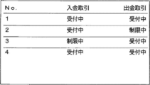
図12及び図13は、第1の実施形態に係る第3表示部31に表示する顧客誘導表示画面を説明する説明図である。
図12に例示する顧客誘導表示画面は、現金処理装置1毎に、入金取引、出金取引を受付中であるか、又は制限中であるかを表形式で表示している。
また、図13に例示する顧客誘導表示画面は、入金取引又は出金取引を受付中であるときには「○」、制限中であるときには「△」と表示している。なお、制限中を「△」としているのは、上述したように、現金処理装置1の収納枚数が顧客誘導閾値に達しているときでも、入金取引又は出金取引自体は可能であるため、「×」とせずに「△」としている。
(A-3)第1の実施形態の効果
以上のように、紙幣カセットの収納枚数が顧客誘導閾値に達したときに、顧客誘導表示画面を表示することで、他の現金処理装置の利用を顧客に誘導できる。その結果、支店に設置されている複数の現金処理装置全体の稼働を平準化でき、現金回収又は現金装填を行なう警送の出動回数を減らすことができる。
以上のように、紙幣カセットの収納枚数が顧客誘導閾値に達したときに、顧客誘導表示画面を表示することで、他の現金処理装置の利用を顧客に誘導できる。その結果、支店に設置されている複数の現金処理装置全体の稼働を平準化でき、現金回収又は現金装填を行なう警送の出動回数を減らすことができる。
(B)第2の実施形態
次に、本発明に係る現金処理装置及びサーバの第2の実施形態を、図面を参照しながら詳細に説明する。
次に、本発明に係る現金処理装置及びサーバの第2の実施形態を、図面を参照しながら詳細に説明する。
第2の実施形態でも、本発明を利用して、金融機関等に設けられているATMに代表される現金処理装置及び現金処理装置の監視等を行なうサーバに適用する場合を例示する。
(B-1)第2の実施形態の構成及び動作
第2の実施形態に係る現金処理システム、現金処理装置及びサーバは、第1の実施形態に係る図1~図5に示す構成要素を有する。従って、第2の実施形態においても、図1~図5を用いて説明する。
第2の実施形態に係る現金処理システム、現金処理装置及びサーバは、第1の実施形態に係る図1~図5に示す構成要素を有する。従って、第2の実施形態においても、図1~図5を用いて説明する。
第2の実施形態は、支店に設置されている複数の現金処理装置1の全体の収納状況に応じて、顧客を誘導する点に特徴がある。
図7は、第2の実施形態に係る顧客誘導表示処理の全体動作を説明する説明図である。
図8は、第2の実施形態に係るサーバ2における顧客誘導表示処理の動作を示すフローチャートである。
まず、サーバ2は、全ての現金処理装置1のそれぞれについて、各紙幣カセット18の収納情報を常時監視している。例えば、サーバ2は、取引を実施している各現金処理装置1に対して各紙幣カセット18の収納枚数を問い合わせる要求信号を送信する。各現金処理装置1は、サーバ2からの問い合せに対して、各紙幣カセット18の収納枚数を返信する。このようにして、サーバ2は、全ての現金処理装置1のそれぞれから各紙幣カセット18の収納枚数を取得する(S201)。
ここで、サーバ2は、図9に例示するように、各グループの現金処理装置1の収納状況を管理している。
図9において、「01」等の数字は、現金処理装置1の識別番号である。「通常」又は「顧客誘導閾値(入金用)超」は、各現金処理装置1の収納状況を示しており、例えば、「顧客誘導閾値(入金用)超」は、「01」の現金処理装置1の収納枚数が顧客誘導閾値(入金用)を超えていることを示しており、「通常」に稼働していることを示している。なお、収納状況は、「ニアフル状態」、「フル状態」、「ニアエンド状態」、「エンド状態」等を管理するようにしても良い。
また、図9において「入金抑制表示」、「非表示」等は、現金処理装置1の表示部(第2表示部32、操作表示部33等)に顧客誘導情表示画面を表示しているか否かを示している。例えば、「入金抑制表示」は、入金を抑制する顧客誘導表示画面を表示していることを示している。
次に、サーバ2において、顧客誘導表示制御部202が、グループ毎に、所定の偏り条件を参照して、グループ内の全ての現金処理装置1の収納状況に基づいて、収納枚数の偏りが生じているか否かを判定する(S202)。
ここで、グループは、特定の現金処理装置1の収納枚数が顧客誘導閾値に達したときに、他の現金処理装置1に顧客を誘導できるグループであり、例えば、金融機関の支店を用いることができる。
また、偏り条件は、同一グループに属する全ての現金処理装置1の収納枚数に偏りがあるか否かを判定するための条件である。
図10及び図11は、第2の実施形態に係る偏り条件を説明する説明図である。ここでは、4台の現金処理装置1が1グループを形成している場合を例示している。
図10(1)は、1グループのうち、2台の現金処理装置1の収納枚数が入金用の顧客誘導閾値(図10では「入金用閾値」と表記している。)に達しており、1台の現金処理装置1の収納枚数が出金用の顧客誘導閾値(図10では「出金用閾値」と表記している。)に達している場合である。このように、一部の現金処理装置1で、入金用又は出金用の顧客誘導閾値に達しているとき、顧客誘導表示制御部202は、「偏っている」と判定し(S203)、偏りの有る現金処理装置1(収納枚数が顧客誘導閾値に達しているもの)に顧客誘導表示画面を表示する(S204)。
図10(2)は、1グループのうち、3台の現金処理装置1の収納枚数が入金用の顧客誘導閾値(「入金用閾値」)に達している場合である。図10(3)は、1グループのうち、3台の現金処理装置1の収納枚数が出金用の顧客誘導閾値(「出金用閾値」)に達している場合である。
図10(2)、図10(3)のように、一部の現金処理装置1の全てが、入金用又は出金用の顧客誘導閾値に達しているとき、顧客誘導表示制御部202は、「偏っていない」と判定し(S203)、顧客誘導表示画面を表示しない(S205)。
このように、1グループのうち、複数の現金処理装置1の収納枚数の状態が同じである場合には、顧客誘導表示画面を表示せず、いずれかの現金処理装置1の収納枚数がフル状態又はエンド状態となれば、現金回収又は現金装填を実施する。なお、現金回収又は現金装填のために、1つのグループ(1つの支店)への係員が出動しても、複数の現金処理装置1について同時に現金回収又は現金装填ができるため、現金回収又は現金装填を効率的に行なうことができる。
図11(1)及び図11(2)は、4台の現金処理装置1のうち、1台の現金処理装置1が障害発生中であり、別の1台の現金処理装置1がサービス外(Out Of Service)である。
このような場合、顧客誘導表示制御部202は、正常に稼働している現金処理装置のそれぞれが、異なる状態(すなわち、収納枚数が、入金用閾値に達しているものと、出金用閾値に達しているものとが混在している)のときには、偏っていると判定し(S203)、顧客誘導表示画面を表示する(S204)。
一方、顧客誘導表示制御部202は、正常に稼働している現金処理装置の全てが、同じ状態(すなわち、全ての現金処理装置1の収納枚数が、入金用閾値又は出金用閾値に達している)のときには、偏っていると判定し(S203)、顧客誘導表示画面を表示しない(S205)。
なお、サーバ2が、各現金処理装置1の第2表示部32、操作表示部33に表示する顧客誘導表示画面は、第1の実施形態と同様に、図6(1)~図6(3)に例示する画面を表示する。
(B-2)第2の実施形態の効果
以上のように、第2の実施形態によれば、第1の実施形態と同様の効果に加えて、グループに属する複数の現金処理装置の収納状況に応じて、顧客誘導表示画面の表示を行なうことができる。
以上のように、第2の実施形態によれば、第1の実施形態と同様の効果に加えて、グループに属する複数の現金処理装置の収納状況に応じて、顧客誘導表示画面の表示を行なうことができる。
(C)第3の実施形態
次に、本発明に係る現金処理装置及びサーバの第3の実施形態を、図面を参照しながら詳細に説明する。
次に、本発明に係る現金処理装置及びサーバの第3の実施形態を、図面を参照しながら詳細に説明する。
第3の実施形態でも、本発明を利用して、金融機関等に設けられているATMに代表される現金処理装置及び現金処理装置の監視等を行なうサーバに適用する場合を例示する。
(C-1)第3の実施形態の構成
図14は、第3の実施形態に係る現金処理装置1Aの制御系の構成を示す構成図である。
図14は、第3の実施形態に係る現金処理装置1Aの制御系の構成を示す構成図である。
図14において、第3の実施形態に係る現金処理装置1Aは、制御部10、記憶部14、通信部15、紙幣認識部17、操作表示部33、第2表示部32、複数(図14では4個)の紙幣カセット18A~18D、入金専用紙幣カセット51、リジェクト庫52を有する。
図14に示すように、現金処理装置1Aは、還流型リサイクルカセットである紙幣カセット18A~18Dの他に、入金専用紙幣カセット51とリジェクト庫52とを有するものである。
ここで、入金専用紙幣カセット51、リジェクト庫52の使用の仕方の一例を説明する。
入金専用紙幣カセット51は、紙幣の集積のみを行ない、収納している紙幣の出金を行なわない紙幣カセットである。つまり、入金専用紙幣カセット51は、紙幣の集積機能を有しているが、還流型リサイクルカセットのように、入金された紙幣を再度出金のために、収納している紙幣を繰り出す機能を有していない。入金専用紙幣カセット51は、一般的に、集積する紙幣の金種制限のないものであり、複数の金種の紙幣を集積できる。
入金専用紙幣カセット51の使用の仕方の一例は、例えば、還流型リサイクルカセットの収納枚数が増え、当該還流型リサイクルカセットがフル状態(若しくはニアフル状態)となり使用できない場合、その後に入金された紙幣を入金専用紙幣カセット51に搬送して集積する。また例えば、入金された紙幣の金種が、各還流型リサイクルカセットに設定されていない場合に、入金された紙幣を入金専用紙幣カセット51に搬送して集積する。
このようにすることで、例えば、還流型リサイクルカセットがフル状態となってしまったときや、還流型リサイクルカセットに設定されてない金種が入金されたときでも、入金専用紙幣カセット51に入金紙幣を集積できる。
また、リジェクト庫52は、紙幣認識部17による鑑別結果に基づいて、リジェクトされた紙幣を保留するものである。リジェクト庫52は、例えば、紙幣認識部17による鑑別結果により、入金された紙幣に汚れや破れ等があり、出金する紙幣として使用できない場合、リジェクト庫52に紙幣を保留する(なお、運用に応じて、汚れや破れ等のある紙幣を入金しよう紙幣カセット51に集積することもある。)。また例えば、紙幣認識部17による真偽判定により偽券と判定された場合等に、偽券と判定された紙幣は顧客に返却するが、還流型リサイクルカセットから出金された紙幣をリジェクト庫52に保留している。
上記のように、入金専用紙幣カセット51、リジェクト庫52等のように、紙幣の集積を行なうが、収納している紙幣を出金に使用しないものを、ここでは「非出金紙幣収納部」呼ぶ。
なお、図14では、現金処理装置1Aが、入金専用紙幣カセット51、リジェクト庫52をそれぞれ1個ずつ設けた場合を例示している。
しかし、現金処理装置1Aは、入金専用紙幣カセット51のみ、又は、リジェクト庫52のみとしても良い。つまり、現金処理装置1Aは、1個の非出金収納部のみを有するものであっても良い。
また、現金処理装置1Aは、複数の入金専用紙幣カセット51を有するものであっても良いし、複数のリジェクト庫52を有するものであっても良い。つまり、現金処理装置1Aは、それぞれ機能や用途の異なるタイプの非出金収納部のそれぞれについて、複数個の非出金収納部を有しても良い。
図14において、現金処理装置1Aは、顧客誘導表示制御部104Aの処理が、第1の実施形態と異なる。従って、第3の実施形態では、顧客誘導表示制御部104Aの処理を詳細に説明する。なお、それ以外の構成要素の処理は、第1の実施形態と同様であるため、ここでの詳細な説明は省略する。
顧客誘導表示制御部104Aは、カセット状態管理部102により管理されている、各紙幣カセット18A~18D、入金専用紙幣カセット51、リジェクト庫52の収納状況に応じて、他の現金処理装置1への利用を顧客に促す顧客誘導表示画面の表示制御を行なう。
ここで、非出金収納部としての入金専用紙幣カセット51、リジェクト庫52の収納枚数については、カセット状態管理部102が管理している。
従来、非出金収納部としての入金専用紙幣カセット51がフル状態となった場合、現金処理装置1Aは入金取引を行うことができなくなり、リジェクト庫52の収納枚数がフル状態となった場合、現金処理装置1Aは入金取引も出金取引も行なうことができない。これら場合も、警送会社の係員が出動して、現金回収が行なわれる。
紙幣カセット18A~18Dの収納枚数が入金取引用の顧客誘導閾値に達したとき、現金処理装置1Aは入金取引について制限されるが、基本的には入金取引を行なえる。
また、紙幣カセット18A~18Dは還流型リサイクルカセットであるため、現金処理装置1Aは出金取引を行なえる。そのため、出金取引が行なわれ、フル状態に近い状態の各紙幣カセット18A~18Dの収納枚数が減れば、現金処理装置1Aは入金取引及び出金取引を制限なく行える。
しかし、入金専用紙幣カセット51、リジェクト庫52の収納枚数がフル状態となってしまうと、現金回収のために、警送会社の係員が出動しなければ、現金処理装置1Aが入金取引及び出金取引を行なえる状態とならない。
そこで、第3の実施形態では、入金専用紙幣カセット51、リジェクト庫52の収納枚数がフル状態となる前に、顧客に他の現金処理装置1Aへの利用を誘導できるようにする。
このように、他の現金処理装置1Aへの利用を顧客に促すことで、支店に設置されている現金処理装置1全体の稼働を平準化できる。他の現金処理装置1Aの稼働を高めることで、係員の出動回数を減らすことができる。
(C-2)第3の実施形態の動作
次に、第3の実施形態に係る顧客誘導表示処理の動作を、図面を参照しながら詳細に説明する。
次に、第3の実施形態に係る顧客誘導表示処理の動作を、図面を参照しながら詳細に説明する。
以下では、第3の実施形態に係る顧客誘導表示処理の3個の動作例を説明する。しかし、非出金収納部の収納状況に応じて顧客誘導表示画面を表示する処理は、以下の3個の動作例に限定されるものではない。
なお、第1の実施形態と同様に、顧客誘導表示画面は、各支店の第3表示部31、各現金処理装置1Aの第2表示部32、各現金処理装置1の操作表示部31のそれぞれ又は全部に表示できる。また、顧客誘導表示画面の表示に係る指示は、各現金処理装置1Aの制御部10、サーバ2の制御部21のいずれかが行なうようにしても良い。
以下では、説明を簡単にするために、各現金処理装置1Aの制御部10が、第2表示部32に顧客誘導表示画面の表示する場合を例示する。
(C-2-1)第1の動作例
図15は、第3の実施形態に係る顧客誘導表示処理の動作を示すフローチャートである。
図15は、第3の実施形態に係る顧客誘導表示処理の動作を示すフローチャートである。
図15において、現金処理装置1の制御部10において、設定部104は、紙幣カセット18A~18D、非出金収納部としての入金専用紙幣カセット51及びリジェクト庫52毎に、顧客誘導閾値が設定されている。
ここで、図15では、入金専用紙幣カセット51及びリジェクト庫52の顧客誘導閾値を顧客誘導閾値(非出金用)と表記している。
また、その実行時点でカセット内に存在している紙幣の枚数を収納枚数と表現している。
現金処理装置1の制御部10は、各紙幣カセット18の収納枚数を紙幣カセット18毎に監視している(S101)。顧客誘導表示制御部104は、各紙幣カセット18の収納枚数と顧客誘導閾値(入金用)とを比較する(S102)。ここで、前取引又は本取引等の取引完了時に、各紙幣カセット18の収納状況が変わる。そのため、取引完了毎に、各紙幣カセット18A~18Dの収納枚数が顧客誘導閾値との比較処理を行なう。
そして、いずれかの紙幣カセット18A~18Dの収納枚数が顧客誘導閾値を超えている場合(S102)、顧客誘導表示制御部104Aは、入金専用紙幣カセット51及びリジェクト庫52の収納枚数を確認する(S301)。
入金専用紙幣カセット51又はリジェクト庫52のいずれかの収納枚数が顧客誘導閾値を超えている場合(S302)、顧客誘導表示制御部104Aは、第2表示部32、操作表示部33に、顧客誘導表示画面を表示する(S104)。
一方、入金専用紙幣カセット51又はリジェクト庫52のいずれかの収納枚数が顧客誘導閾値を超えていない場合(S302)、処理はS103に移行する。
このように、還流型リサイクルカセットである紙幣カセット18A~18Dのいずれかの収納枚数が顧客誘導閾値(入金用)に達している場合であって、入金専用紙幣カセット51又はリジェクト庫52のいずれかの収納枚数が顧客誘導閾値を超えているときに、顧客誘導表示画面を表示する。これにより、現金処理装置1Aは入金取引を制限するが、出金取引を受け付けることができる。
そのため、出金取引により紙幣カセット18A~18Dの収納枚数が減り、その後、通常の入金取引が可能となる。また、入金専用紙幣カセット51、リジェクト庫52の収納枚数がフル状態となる前に、顧客に他の現金処理装置1Aへの利用を誘導できる。
なお、S103~S105の処理は、第1の実施形態と同様であるため、ここでの詳細な説明は省略する。
(C-2-2)第2の動作例
図16は、第3の実施形態に係る顧客誘導表示処理の動作を示すフローチャートである。
図16は、第3の実施形態に係る顧客誘導表示処理の動作を示すフローチャートである。
図16において、現金処理装置1の制御部10において、設定部104は、紙幣カセット18A~18D、非出金収納部としての入金専用紙幣カセット51及びリジェクト庫52毎に、顧客誘導閾値が設定されている。
現金処理装置1の制御部10は、各紙幣カセット18の収納枚数を紙幣カセット18毎に監視している(S101)。顧客誘導表示制御部104は、還流型リサイクルカセットである各紙幣カセット18の収納状況がフル状態(又はニアフル状態)であるか否かを判断する(S401)。
還流型リサイクルカセットである各紙幣カセット18の収納状況がフル状態(又はニアフル状態)でない場合、顧客誘導表示制御部104は、還流型リサイクルカセットである各紙幣カセット18の収納状況がエンド状態(又はニアエンド状態)であるか否かを判断する(S402)。ここで、還流型リサイクルカセットである各紙幣カセット18の収納状況がフル状態(又はニアフル状態)でなく、かつ、エンド状態(又はニアエンド状態)でない場合、S101に戻る。
還流型リサイクルカセットである各紙幣カセット18の収納状況がフル状態(又はニアフル状態)である場合、又は、還流型リサイクルカセットである各紙幣カセット18の収納状況がエンド状態(又はニアエンド状態)である場合、顧客誘導表示制御部104Aは、入金専用紙幣カセット51及びリジェクト庫52の収納枚数を確認する(S403)。
入金専用紙幣カセット51又はリジェクト庫52のいずれかの収納枚数が顧客誘導閾値を超えている場合(S404)、顧客誘導表示制御部104Aは、第2表示部32、操作表示部33に、顧客誘導表示画面を表示する(S104)。
一方、入金専用紙幣カセット51又はリジェクト庫52のいずれかの収納枚数が顧客誘導閾値を超えていない場合(S404)、顧客誘導表示制御部104Aは、第2表示部32、操作表示部33に、顧客誘導表示画面を表示しない(S105)。
このように、還流型リサイクルカセットである紙幣カセット18A~18Dのいずれかのフル状態(若しくはニアフル状態)の場合、顧客を他の現金処理装置1Aに誘導できる。その結果、入金専用紙幣カセット51、リジェクト庫52の収納枚数がフル状態となる前に、顧客に他の現金処理装置1Aへの利用を誘導できる。
(C-2-3)第3の動作例
図17は、第3の実施形態に係る顧客誘導表示処理の動作を示すフローチャートである。
図17は、第3の実施形態に係る顧客誘導表示処理の動作を示すフローチャートである。
図17において、現金処理装置1の制御部10において、設定部104は、紙幣カセット18A~18D、非出金収納部としての入金専用紙幣カセット51及びリジェクト庫52毎に、顧客誘導閾値が設定されている。
現金処理装置1の制御部10は、各紙幣カセット18の収納枚数を紙幣カセット18毎に監視している(S101)。顧客誘導表示制御部104は、非出金収納部である入金専用紙幣カセット51及びリジェクト庫52の収納枚数を確認する(S401)。
入金専用紙幣カセット51又はリジェクト庫52のいずれかの収納枚数が顧客誘導閾値を超えている場合(S404)、顧客誘導表示制御部104Aは、第2表示部32、操作表示部33に、顧客誘導表示画面を表示する(S104)。
一方、入金専用紙幣カセット51又はリジェクト庫52のいずれかの収納枚数が顧客誘導閾値を超えていない場合(S404)、顧客誘導表示制御部104Aは、第2表示部32、操作表示部33に、顧客誘導表示画面を表示しない(S105)。
図17に示す動作処理は、還流型リサイクルカセットである紙幣カセット18A~18Dのいずれかの収納枚数が、フル状態(若しくはニアフル状態)又は顧客誘導閾値に達している状態でない場合でも、入金専用紙幣カセット51、リジェクト庫52の収納枚数がフル状態となる前に、顧客に他の現金処理装置1Aへの利用を誘導できる。
(C-3)第3の実施形態の効果
以上のように、第3の実施形態によれば、第1の実施形態と同様の効果に加えて、入金専用紙幣カセット51、リジェクト庫52の収納枚数がフル状態となる前に、顧客に他の現金処理装置1Aへの利用を誘導できる。
以上のように、第3の実施形態によれば、第1の実施形態と同様の効果に加えて、入金専用紙幣カセット51、リジェクト庫52の収納枚数がフル状態となる前に、顧客に他の現金処理装置1Aへの利用を誘導できる。
(D)他の実施形態
上述した第1~第3の実施形態においても種々の変形実施形態を言及したが、本発明は、以下のような変形実施形態にも適用できる。
上述した第1~第3の実施形態においても種々の変形実施形態を言及したが、本発明は、以下のような変形実施形態にも適用できる。
(D-1)上述した第1~第3の実施形態では、各現金処理装置が備える複数の紙幣カセットのうち、いずれか1つの収納状況が、顧客誘導閾値を超えている場合に、顧客誘導表示画面を表示する場合を例示した。
しかし、各現金処理装置1の制御部10、サーバ2の制御部21は、現金処理装置1の各紙幣カセットの収納状況も管理している。そのため、複数の紙幣カセットのうち、1万円の紙幣カセットのみの収納枚数が顧客誘導閾値に達したときには、例えば、「1万円の入金取引(又は出金取引)は制限中」等のように、金種毎に、取引を抑制する顧客誘導表示画面を表示するようにしても良い。
(D-2)上述した第1~第3の実施形態において、設定部103、設定部201は、金融機関等の保守者が手動で設定するようにしても良い。
また、設定部103、設定部201は、過去の各現金処理装置1の各紙幣カセットの収納枚数の変動データの統計データや分析データから導いた値を顧客誘導閾値として設定するようにしても良い。より具体的には、現金処理装置1の利用頻度は、平日、祝休日等によって変動するものである。従って、時間的な要因に基づく利用頻度を考慮した値を設定できるようにしても良い。
(D-3)上述した第3の実施形態において、非出金収納部としての入金専用紙幣カセット51及びリジェクト庫52の収納状況を、顧客誘導表示制御部が判定する場合を例示した。しかし、非出金収納部としての入金専用紙幣カセット51及びリジェクト庫52には、収納枚数を検知するセンサが設けられており、これらセンサからの通知を受けて、顧客誘導表示制御部が非出金収納部の収納枚数を確認でき、顧客誘導表示閾値との比較を判断するようにしても良い。
2015年12月14日に出願された日本国特許出願2015-243296号の開示は、その全体が参照により本明細書に取り込まれる。
Claims (10)
- 紙幣を収納する複数の紙幣収納部と、
前記紙幣収納部の各々の内の収納状況を管理する収納状況管理部と、
前記紙幣収納部の各々の内の収納状況に応じて、複数種類の取引のうち、特定の取引を抑制し、及び又は、特定の取引以外の取引を促成する表示画面を表示する表示制御部と
を備えることを特徴とする現金処理装置。 - 前記表示制御部が、前記紙幣収納部の各々の収納枚数と、取引抑制に係る閾値とを比較し、前記収納枚数の各々が閾値に達したときに、前記表示画面を表示することを特徴とする請求項1に記載の現金処理装置。
- 顧客操作に用いる主たる第1表示部と、
前記第1表示部とは異なる第2表示部と
を有し、
前記表示制御部が、前記第1表示部と前記第2表示部のいずれか又は両方に、前記表示画面を表示することを特徴とする請求項1又は2に記載の現金処理装置。 - 複数の金種の紙幣を収納する1又は複数の非出金収納部を更に備え、
前記表示制御部が、前記紙幣収納部の各々の収納枚数がフル状態又は閾値に達しており、前記非出金収納部の各々の収納枚数が閾値に達しているときに、前記表示画面を表示することを特徴とする請求項1~3のいずれか一項に記載の現金処理装置。 - 複数の紙幣収納部を有する複数の現金処理装置のそれぞれの収納状況を管理するサーバにおいて、
前記現金処理装置の各々から取得した前記紙幣収納部の各々の収納状況を管理する収納状況管理部と、
前記現金処理装置の各々の前記紙幣収納部の各々の内の収納状況に応じて、複数種類の取引のうち、特定の取引を抑制し、又は、特定の取引以外の取引を促成する表示画面を表示する表示制御部と
を有することを特徴とするサーバ。 - 前記表示制御部が、前記現金処理装置の各紙幣収納部の収納枚数と、取引抑制に係る閾値とを比較し、前記収納枚数の各々が閾値に達したときに、前記表示画面を表示することを特徴とする請求項5に記載のサーバ。
- 前記現金処理装置の各々が、複数の金種の紙幣を収納する1又は複数の非出金収納部を有するものであり、
前記表示制御部が、前記現金処理装置の各々について、前記紙幣収納部の各々の収納枚数がフル状態又は閾値に達しており、前記非出金収納部の各々の収納枚数が閾値に達しているときに、前記表示画面を表示することを特徴とする請求項5又は6に記載のサーバ。 - 前記収納状況管理部が、前記現金処理装置の各々の属するグループ毎に、前記現金処理装置の各々の収納状況を管理するものであり、
前記表示制御部が、前記現金処理装置の各々の各紙幣収納部の収納枚数が、取引抑制に係る閾値に達すると、前記現金処理装置の属するグループ毎に、他の現金処理装置の収納状況を判定した判定結果に応じて、前記表示画面の表示の有無を判断する
ことを特徴とする請求項5に記載のサーバ。 - 前記表示制御部が、前記表示画面を、前記収納枚数が閾値に達した現金処理装置の有する表示部に表示させることを特徴とする請求項6~8のいずれか一項に記載のサーバ。
- 前記表示制御部が、複数の現金処理装置のそれぞれの全体の状態を一覧表示する第3表示部に、前記表示画面を表示することを特徴とする請求項5~8のいずれか一項に記載のサーバ。
Priority Applications (1)
| Application Number | Priority Date | Filing Date | Title |
|---|---|---|---|
| US15/777,094 US10692320B2 (en) | 2015-12-14 | 2016-10-14 | Cash processing device and server |
Applications Claiming Priority (2)
| Application Number | Priority Date | Filing Date | Title |
|---|---|---|---|
| JP2015-243296 | 2015-12-14 | ||
| JP2015243296A JP6679916B2 (ja) | 2015-12-14 | 2015-12-14 | 現金処理装置及びサーバ |
Publications (1)
| Publication Number | Publication Date |
|---|---|
| WO2017104247A1 true WO2017104247A1 (ja) | 2017-06-22 |
Family
ID=59056519
Family Applications (1)
| Application Number | Title | Priority Date | Filing Date |
|---|---|---|---|
| PCT/JP2016/080600 Ceased WO2017104247A1 (ja) | 2015-12-14 | 2016-10-14 | 現金処理装置及びサーバ |
Country Status (3)
| Country | Link |
|---|---|
| US (1) | US10692320B2 (ja) |
| JP (1) | JP6679916B2 (ja) |
| WO (1) | WO2017104247A1 (ja) |
Families Citing this family (12)
| Publication number | Priority date | Publication date | Assignee | Title |
|---|---|---|---|---|
| WO2019188880A1 (ja) * | 2018-03-26 | 2019-10-03 | グローリー株式会社 | 紙葉類処理装置 |
| CN111243162B (zh) * | 2020-01-15 | 2022-11-22 | 山东新北洋信息技术股份有限公司 | 纸币集积装置的控制方法、装置和现金处理设备 |
| JP7493988B2 (ja) * | 2020-04-15 | 2024-06-03 | グローリー株式会社 | 紙葉類処理システム、紙葉類処理方法、および決定装置 |
| JP7477387B2 (ja) | 2020-07-22 | 2024-05-01 | グローリー株式会社 | 紙葉類処理装置および紙葉類処理方法 |
| JP7588488B2 (ja) * | 2020-09-25 | 2024-11-22 | グローリー株式会社 | 管理システム |
| JP7645644B2 (ja) * | 2021-01-19 | 2025-03-14 | グローリー株式会社 | 貨幣処理方法及び貨幣処理システム |
| JP2022127098A (ja) * | 2021-02-19 | 2022-08-31 | グローリー株式会社 | 媒体処理方法 |
| US11620878B1 (en) | 2021-03-18 | 2023-04-04 | Wells Fargo Bank, N.A. | Universal cassette for recirculation of bills in multiple systems |
| US11830327B1 (en) | 2021-10-08 | 2023-11-28 | Wells Fargo Bank, N.A. | Systems and methods for retrofit housing for transaction devices |
| US11699331B1 (en) | 2021-10-08 | 2023-07-11 | Wells Fargo Bank, N.A. | Systems and methods for retrofit housing for transaction devices |
| US12100256B1 (en) * | 2021-10-08 | 2024-09-24 | Wells Fargo Bank, N.A. | Systems and methods for retrofit housing using an in-safe cassette port |
| JP2025030411A (ja) * | 2023-08-23 | 2025-03-07 | グローリー株式会社 | 貨幣処理装置及び貨幣処理方法 |
Citations (3)
| Publication number | Priority date | Publication date | Assignee | Title |
|---|---|---|---|---|
| JPH06144696A (ja) * | 1992-11-05 | 1994-05-24 | Laurel Bank Mach Co Ltd | 自動取引処理装置 |
| JP2000339516A (ja) * | 1999-05-25 | 2000-12-08 | Fujitsu Ltd | 顧客誘導システム |
| JP2011164946A (ja) * | 2010-02-10 | 2011-08-25 | Hitachi Omron Terminal Solutions Corp | 自動取引装置 |
Family Cites Families (6)
| Publication number | Priority date | Publication date | Assignee | Title |
|---|---|---|---|---|
| JP3097744B2 (ja) * | 1989-07-19 | 2000-10-10 | オムロン株式会社 | 現金取引装置の管理システム |
| JPH1125352A (ja) | 1997-07-09 | 1999-01-29 | Oki Electric Ind Co Ltd | 顧客誘導システム、自動取引装置及び誘導情報管理装置 |
| EP1332458A1 (en) * | 2000-10-02 | 2003-08-06 | Efunds Corporation | Method and apparatus for managing automated banking machines |
| US9171416B2 (en) * | 2010-01-29 | 2015-10-27 | Glory Ltd. | Banknote handling apparatus and banknote handling method |
| JP6409502B2 (ja) * | 2014-03-31 | 2018-10-24 | 沖電気工業株式会社 | 媒体処理装置及び媒体取引装置 |
| US10365805B2 (en) * | 2015-06-30 | 2019-07-30 | Bank Of America Corporation | Automated device assistance |
-
2015
- 2015-12-14 JP JP2015243296A patent/JP6679916B2/ja active Active
-
2016
- 2016-10-14 WO PCT/JP2016/080600 patent/WO2017104247A1/ja not_active Ceased
- 2016-10-14 US US15/777,094 patent/US10692320B2/en active Active
Patent Citations (3)
| Publication number | Priority date | Publication date | Assignee | Title |
|---|---|---|---|---|
| JPH06144696A (ja) * | 1992-11-05 | 1994-05-24 | Laurel Bank Mach Co Ltd | 自動取引処理装置 |
| JP2000339516A (ja) * | 1999-05-25 | 2000-12-08 | Fujitsu Ltd | 顧客誘導システム |
| JP2011164946A (ja) * | 2010-02-10 | 2011-08-25 | Hitachi Omron Terminal Solutions Corp | 自動取引装置 |
Also Published As
| Publication number | Publication date |
|---|---|
| JP6679916B2 (ja) | 2020-04-15 |
| US20180330563A1 (en) | 2018-11-15 |
| US10692320B2 (en) | 2020-06-23 |
| JP2017111494A (ja) | 2017-06-22 |
Similar Documents
| Publication | Publication Date | Title |
|---|---|---|
| JP6679916B2 (ja) | 現金処理装置及びサーバ | |
| JP5439489B2 (ja) | 貨幣処理装置 | |
| WO2013145600A1 (ja) | 貨幣処理装置 | |
| EP1349126A2 (en) | Automatic transaction machine | |
| JP5169474B2 (ja) | 紙幣入出金機 | |
| JP5178012B2 (ja) | 自動取引装置 | |
| CN102385770B (zh) | 纸张类处理装置 | |
| JP2009104678A (ja) | 現金自動取引装置 | |
| JP4387372B2 (ja) | 紙幣処理装置 | |
| JPS5887692A (ja) | 取引処理装置の動作方法 | |
| JP2008027023A (ja) | 現金処理装置 | |
| JP4387456B1 (ja) | 現金自動取引装置 | |
| JP2015114999A (ja) | 現金処理装置及び現金処理方法 | |
| JP2020091920A (ja) | 現金処理装置 | |
| JP2004252941A (ja) | 自動取引装置およびそのプログラム | |
| JP5951392B2 (ja) | 貨幣処理システムおよび貨幣処理方法 | |
| JP2761311B2 (ja) | 現金取扱装置 | |
| JP6452976B2 (ja) | 現金処理装置 | |
| JP2013127738A (ja) | 自動取引装置及び自動取引プログラム | |
| JP2007241762A (ja) | 紙幣入出金機およびその紙幣入出金機を搭載した自動取引装置 | |
| JP6500647B2 (ja) | 紙幣処理装置 | |
| JP2974532B2 (ja) | 自動取引装置 | |
| JP2014132407A (ja) | 施封小束支払機および現金処理装置 | |
| JP2014026339A (ja) | 貨幣処理システムおよび貨幣処理方法 | |
| JP5396303B2 (ja) | 自動取引装置 |
Legal Events
| Date | Code | Title | Description |
|---|---|---|---|
| 121 | Ep: the epo has been informed by wipo that ep was designated in this application |
Ref document number: 16875232 Country of ref document: EP Kind code of ref document: A1 |
|
| WWE | Wipo information: entry into national phase |
Ref document number: 15777094 Country of ref document: US |
|
| NENP | Non-entry into the national phase |
Ref country code: DE |
|
| 122 | Ep: pct application non-entry in european phase |
Ref document number: 16875232 Country of ref document: EP Kind code of ref document: A1 |