WO2017104243A1 - ガス化装置、ガス化装置の制御装置及び方法、ガス化複合発電設備 - Google Patents
ガス化装置、ガス化装置の制御装置及び方法、ガス化複合発電設備 Download PDFInfo
- Publication number
- WO2017104243A1 WO2017104243A1 PCT/JP2016/080231 JP2016080231W WO2017104243A1 WO 2017104243 A1 WO2017104243 A1 WO 2017104243A1 JP 2016080231 W JP2016080231 W JP 2016080231W WO 2017104243 A1 WO2017104243 A1 WO 2017104243A1
- Authority
- WO
- WIPO (PCT)
- Prior art keywords
- pressure
- gas
- gasification furnace
- gasifier
- pressure difference
- Prior art date
- Legal status (The legal status is an assumption and is not a legal conclusion. Google has not performed a legal analysis and makes no representation as to the accuracy of the status listed.)
- Ceased
Links
Images
Classifications
-
- F—MECHANICAL ENGINEERING; LIGHTING; HEATING; WEAPONS; BLASTING
- F01—MACHINES OR ENGINES IN GENERAL; ENGINE PLANTS IN GENERAL; STEAM ENGINES
- F01K—STEAM ENGINE PLANTS; STEAM ACCUMULATORS; ENGINE PLANTS NOT OTHERWISE PROVIDED FOR; ENGINES USING SPECIAL WORKING FLUIDS OR CYCLES
- F01K23/00—Plants characterised by more than one engine delivering power external to the plant, the engines being driven by different fluids
- F01K23/02—Plants characterised by more than one engine delivering power external to the plant, the engines being driven by different fluids the engine cycles being thermally coupled
- F01K23/06—Plants characterised by more than one engine delivering power external to the plant, the engines being driven by different fluids the engine cycles being thermally coupled combustion heat from one cycle heating the fluid in another cycle
- F01K23/067—Plants characterised by more than one engine delivering power external to the plant, the engines being driven by different fluids the engine cycles being thermally coupled combustion heat from one cycle heating the fluid in another cycle the combustion heat coming from a gasification or pyrolysis process, e.g. coal gasification
-
- C—CHEMISTRY; METALLURGY
- C10—PETROLEUM, GAS OR COKE INDUSTRIES; TECHNICAL GASES CONTAINING CARBON MONOXIDE; FUELS; LUBRICANTS; PEAT
- C10J—PRODUCTION OF PRODUCER GAS, WATER-GAS, SYNTHESIS GAS FROM SOLID CARBONACEOUS MATERIAL, OR MIXTURES CONTAINING THESE GASES; CARBURETTING AIR OR OTHER GASES
- C10J3/00—Production of combustible gases containing carbon monoxide from solid carbonaceous fuels
- C10J3/46—Gasification of granular or pulverulent flues in suspension
- C10J3/48—Apparatus; Plants
-
- C—CHEMISTRY; METALLURGY
- C10—PETROLEUM, GAS OR COKE INDUSTRIES; TECHNICAL GASES CONTAINING CARBON MONOXIDE; FUELS; LUBRICANTS; PEAT
- C10J—PRODUCTION OF PRODUCER GAS, WATER-GAS, SYNTHESIS GAS FROM SOLID CARBONACEOUS MATERIAL, OR MIXTURES CONTAINING THESE GASES; CARBURETTING AIR OR OTHER GASES
- C10J3/00—Production of combustible gases containing carbon monoxide from solid carbonaceous fuels
- C10J3/46—Gasification of granular or pulverulent flues in suspension
- C10J3/48—Apparatus; Plants
- C10J3/485—Entrained flow gasifiers
-
- C—CHEMISTRY; METALLURGY
- C10—PETROLEUM, GAS OR COKE INDUSTRIES; TECHNICAL GASES CONTAINING CARBON MONOXIDE; FUELS; LUBRICANTS; PEAT
- C10J—PRODUCTION OF PRODUCER GAS, WATER-GAS, SYNTHESIS GAS FROM SOLID CARBONACEOUS MATERIAL, OR MIXTURES CONTAINING THESE GASES; CARBURETTING AIR OR OTHER GASES
- C10J3/00—Production of combustible gases containing carbon monoxide from solid carbonaceous fuels
- C10J3/72—Other features
- C10J3/723—Controlling or regulating the gasification process
-
- C—CHEMISTRY; METALLURGY
- C10—PETROLEUM, GAS OR COKE INDUSTRIES; TECHNICAL GASES CONTAINING CARBON MONOXIDE; FUELS; LUBRICANTS; PEAT
- C10J—PRODUCTION OF PRODUCER GAS, WATER-GAS, SYNTHESIS GAS FROM SOLID CARBONACEOUS MATERIAL, OR MIXTURES CONTAINING THESE GASES; CARBURETTING AIR OR OTHER GASES
- C10J3/00—Production of combustible gases containing carbon monoxide from solid carbonaceous fuels
- C10J3/72—Other features
- C10J3/726—Start-up
-
- C—CHEMISTRY; METALLURGY
- C10—PETROLEUM, GAS OR COKE INDUSTRIES; TECHNICAL GASES CONTAINING CARBON MONOXIDE; FUELS; LUBRICANTS; PEAT
- C10J—PRODUCTION OF PRODUCER GAS, WATER-GAS, SYNTHESIS GAS FROM SOLID CARBONACEOUS MATERIAL, OR MIXTURES CONTAINING THESE GASES; CARBURETTING AIR OR OTHER GASES
- C10J3/00—Production of combustible gases containing carbon monoxide from solid carbonaceous fuels
- C10J3/72—Other features
- C10J3/74—Construction of shells or jackets
-
- C—CHEMISTRY; METALLURGY
- C10—PETROLEUM, GAS OR COKE INDUSTRIES; TECHNICAL GASES CONTAINING CARBON MONOXIDE; FUELS; LUBRICANTS; PEAT
- C10J—PRODUCTION OF PRODUCER GAS, WATER-GAS, SYNTHESIS GAS FROM SOLID CARBONACEOUS MATERIAL, OR MIXTURES CONTAINING THESE GASES; CARBURETTING AIR OR OTHER GASES
- C10J2300/00—Details of gasification processes
- C10J2300/09—Details of the feed, e.g. feeding of spent catalyst, inert gas or halogens
- C10J2300/0913—Carbonaceous raw material
- C10J2300/093—Coal
-
- C—CHEMISTRY; METALLURGY
- C10—PETROLEUM, GAS OR COKE INDUSTRIES; TECHNICAL GASES CONTAINING CARBON MONOXIDE; FUELS; LUBRICANTS; PEAT
- C10J—PRODUCTION OF PRODUCER GAS, WATER-GAS, SYNTHESIS GAS FROM SOLID CARBONACEOUS MATERIAL, OR MIXTURES CONTAINING THESE GASES; CARBURETTING AIR OR OTHER GASES
- C10J2300/00—Details of gasification processes
- C10J2300/09—Details of the feed, e.g. feeding of spent catalyst, inert gas or halogens
- C10J2300/0913—Carbonaceous raw material
- C10J2300/094—Char
-
- C—CHEMISTRY; METALLURGY
- C10—PETROLEUM, GAS OR COKE INDUSTRIES; TECHNICAL GASES CONTAINING CARBON MONOXIDE; FUELS; LUBRICANTS; PEAT
- C10J—PRODUCTION OF PRODUCER GAS, WATER-GAS, SYNTHESIS GAS FROM SOLID CARBONACEOUS MATERIAL, OR MIXTURES CONTAINING THESE GASES; CARBURETTING AIR OR OTHER GASES
- C10J2300/00—Details of gasification processes
- C10J2300/16—Integration of gasification processes with another plant or parts within the plant
- C10J2300/164—Integration of gasification processes with another plant or parts within the plant with conversion of synthesis gas
- C10J2300/1643—Conversion of synthesis gas to energy
- C10J2300/1653—Conversion of synthesis gas to energy integrated in a gasification combined cycle [IGCC]
-
- C—CHEMISTRY; METALLURGY
- C10—PETROLEUM, GAS OR COKE INDUSTRIES; TECHNICAL GASES CONTAINING CARBON MONOXIDE; FUELS; LUBRICANTS; PEAT
- C10J—PRODUCTION OF PRODUCER GAS, WATER-GAS, SYNTHESIS GAS FROM SOLID CARBONACEOUS MATERIAL, OR MIXTURES CONTAINING THESE GASES; CARBURETTING AIR OR OTHER GASES
- C10J2300/00—Details of gasification processes
- C10J2300/16—Integration of gasification processes with another plant or parts within the plant
- C10J2300/1671—Integration of gasification processes with another plant or parts within the plant with the production of electricity
- C10J2300/1675—Integration of gasification processes with another plant or parts within the plant with the production of electricity making use of a steam turbine
-
- C—CHEMISTRY; METALLURGY
- C10—PETROLEUM, GAS OR COKE INDUSTRIES; TECHNICAL GASES CONTAINING CARBON MONOXIDE; FUELS; LUBRICANTS; PEAT
- C10J—PRODUCTION OF PRODUCER GAS, WATER-GAS, SYNTHESIS GAS FROM SOLID CARBONACEOUS MATERIAL, OR MIXTURES CONTAINING THESE GASES; CARBURETTING AIR OR OTHER GASES
- C10J2300/00—Details of gasification processes
- C10J2300/18—Details of the gasification process, e.g. loops, autothermal operation
- C10J2300/1861—Heat exchange between at least two process streams
- C10J2300/1884—Heat exchange between at least two process streams with one stream being synthesis gas
-
- C—CHEMISTRY; METALLURGY
- C10—PETROLEUM, GAS OR COKE INDUSTRIES; TECHNICAL GASES CONTAINING CARBON MONOXIDE; FUELS; LUBRICANTS; PEAT
- C10J—PRODUCTION OF PRODUCER GAS, WATER-GAS, SYNTHESIS GAS FROM SOLID CARBONACEOUS MATERIAL, OR MIXTURES CONTAINING THESE GASES; CARBURETTING AIR OR OTHER GASES
- C10J2300/00—Details of gasification processes
- C10J2300/18—Details of the gasification process, e.g. loops, autothermal operation
- C10J2300/1861—Heat exchange between at least two process streams
- C10J2300/1892—Heat exchange between at least two process streams with one stream being water/steam
-
- F—MECHANICAL ENGINEERING; LIGHTING; HEATING; WEAPONS; BLASTING
- F01—MACHINES OR ENGINES IN GENERAL; ENGINE PLANTS IN GENERAL; STEAM ENGINES
- F01K—STEAM ENGINE PLANTS; STEAM ACCUMULATORS; ENGINE PLANTS NOT OTHERWISE PROVIDED FOR; ENGINES USING SPECIAL WORKING FLUIDS OR CYCLES
- F01K23/00—Plants characterised by more than one engine delivering power external to the plant, the engines being driven by different fluids
- F01K23/02—Plants characterised by more than one engine delivering power external to the plant, the engines being driven by different fluids the engine cycles being thermally coupled
- F01K23/06—Plants characterised by more than one engine delivering power external to the plant, the engines being driven by different fluids the engine cycles being thermally coupled combustion heat from one cycle heating the fluid in another cycle
- F01K23/10—Plants characterised by more than one engine delivering power external to the plant, the engines being driven by different fluids the engine cycles being thermally coupled combustion heat from one cycle heating the fluid in another cycle with exhaust fluid of one cycle heating the fluid in another cycle
-
- Y—GENERAL TAGGING OF NEW TECHNOLOGICAL DEVELOPMENTS; GENERAL TAGGING OF CROSS-SECTIONAL TECHNOLOGIES SPANNING OVER SEVERAL SECTIONS OF THE IPC; TECHNICAL SUBJECTS COVERED BY FORMER USPC CROSS-REFERENCE ART COLLECTIONS [XRACs] AND DIGESTS
- Y02—TECHNOLOGIES OR APPLICATIONS FOR MITIGATION OR ADAPTATION AGAINST CLIMATE CHANGE
- Y02E—REDUCTION OF GREENHOUSE GAS [GHG] EMISSIONS, RELATED TO ENERGY GENERATION, TRANSMISSION OR DISTRIBUTION
- Y02E20/00—Combustion technologies with mitigation potential
- Y02E20/16—Combined cycle power plant [CCPP], or combined cycle gas turbine [CCGT]
-
- Y—GENERAL TAGGING OF NEW TECHNOLOGICAL DEVELOPMENTS; GENERAL TAGGING OF CROSS-SECTIONAL TECHNOLOGIES SPANNING OVER SEVERAL SECTIONS OF THE IPC; TECHNICAL SUBJECTS COVERED BY FORMER USPC CROSS-REFERENCE ART COLLECTIONS [XRACs] AND DIGESTS
- Y02—TECHNOLOGIES OR APPLICATIONS FOR MITIGATION OR ADAPTATION AGAINST CLIMATE CHANGE
- Y02E—REDUCTION OF GREENHOUSE GAS [GHG] EMISSIONS, RELATED TO ENERGY GENERATION, TRANSMISSION OR DISTRIBUTION
- Y02E20/00—Combustion technologies with mitigation potential
- Y02E20/16—Combined cycle power plant [CCPP], or combined cycle gas turbine [CCGT]
- Y02E20/18—Integrated gasification combined cycle [IGCC], e.g. combined with carbon capture and storage [CCS]
-
- Y—GENERAL TAGGING OF NEW TECHNOLOGICAL DEVELOPMENTS; GENERAL TAGGING OF CROSS-SECTIONAL TECHNOLOGIES SPANNING OVER SEVERAL SECTIONS OF THE IPC; TECHNICAL SUBJECTS COVERED BY FORMER USPC CROSS-REFERENCE ART COLLECTIONS [XRACs] AND DIGESTS
- Y02—TECHNOLOGIES OR APPLICATIONS FOR MITIGATION OR ADAPTATION AGAINST CLIMATE CHANGE
- Y02P—CLIMATE CHANGE MITIGATION TECHNOLOGIES IN THE PRODUCTION OR PROCESSING OF GOODS
- Y02P20/00—Technologies relating to chemical industry
- Y02P20/10—Process efficiency
- Y02P20/129—Energy recovery, e.g. by cogeneration, H2recovery or pressure recovery turbines
Definitions
- the present invention relates to a gasifier that generates gas fuel by partially burning carbon-containing solid fuel such as coal and biomass to gasify, a control device and a method for the gasifier, and a gasification equipped with the gasifier It relates to combined power generation facilities.
- the gasification combined power generation facility (coal gasification combined power generation facility) is composed of a coal supply device, a coal gasification device, a gas purification device, a gas turbine facility, a steam turbine facility, an exhaust heat recovery boiler, a gas purification device, and the like.
- a coal gasification apparatus has a gasification furnace disposed in a pressure vessel, a combustion apparatus is disposed vertically below the gasification furnace, and a heat exchanger (gas cooling) vertically above. Device) is arranged.
- the coal gasification apparatus is maintaining the inside of a gasification furnace in a high pressure state by filling the annulus part (pressure holding part) between a pressure vessel and a gasification furnace with inert gas, such as nitrogen. .
- the gasification furnace and the annulus portion communicate with each other through a pressure equalizing pipe, thereby suppressing an increase in the differential pressure between the gasification furnace and the annulus portion due to pressure fluctuation in the gasification furnace.
- Examples of such a coal gasifier include those described in Patent Documents 1 and 2 below.
- the fuel supply amount fluctuates when the load increases, the pressure in the gasifier rises, and the generated gas in the gasifier flows to the annulus through the pressure equalization pipe.
- the rise in the differential pressure between the inside and the annulus is suppressed.
- the annulus section supplies a pressurizing gas such as nitrogen to maintain the pressure of the annulus section, so that the product gas flowing from the gasifier to the annulus section returns to the gasifier.
- the annulus can maintain an inert gas atmosphere.
- the product gas contains unreacted components and ash (hereinafter referred to as char), and the char may flow into the annulus with the product gas.
- the coal gasifier is provided with a slag hopper for storing water at the lower end, and there is a risk that the char flowing into the annulus will contaminate the annulus.
- the present invention solves the above-described problems, and a gasification apparatus and a gas that can suppress the flow of product gas to an annulus part (pressure holding part) through a pressure equalizing pipe with respect to pressure fluctuation in a gasification furnace It aims at providing the control apparatus and method of gasification apparatus, and the gasification combined cycle power generation equipment.
- a gasification apparatus of the present invention comprises a gasification furnace for gasifying a carbon-containing fuel, a pressure vessel for storing the gasification furnace, and the gasification furnace and the pressure vessel.
- a pressure holding unit filled with a pressurizing gas a pressurizing gas supply device that supplies the pressurizing gas to the pressure holding unit, and a pressure equalizing pipe that communicates the inside of the gasification furnace and the pressure holding unit.
- a pressure difference detection estimation device for detecting or estimating a first pressure difference between the first pressure on the gasifier side and the second pressure on the pressure holding unit side, and a detection result or an estimation result of the pressure difference detection estimation device
- a control device for controlling the pressurization gas supply device so that the second pressure is higher than the first pressure
- the gasification furnace is housed in the pressure vessel, and a pressure holding unit is defined between the two.
- the inside of the gasification furnace and the pressure holding unit communicate with each other through a pressure equalizing pipe, and the pressurization gas supply device is pressurized.
- the pressurization gas supply device is pressurized.
- the pressure in the gasification furnace may increase due to pressure fluctuations in the gasification furnace, and may be higher than the pressure holding unit.
- the pressure difference detection estimation device detects or estimates a first pressure difference between the first pressure on the gasifier side and the second pressure on the pressure holding unit side.
- the control device controls the pressurization gas supply device so that the second pressure is higher than the first pressure based on the detection result or the estimation result of the pressure difference detection estimation device. Therefore, even if the pressure in the gasification furnace rises, it is possible to suppress the generated gas in the gasification furnace from flowing into the pressure holding part through the pressure equalizing pipe by further increasing the pressure in the pressure holding part. it can.
- the pressure difference detection estimation apparatus is separated from the pressure equalizing pipe in the gas flow direction and detects a first pressure of the gasification furnace, and a gas flow from the pressure equalizing pipe.
- a second pressure sensor that detects the second pressure of the pressure holding portion spaced apart in the direction, and a calculation that calculates the first pressure difference from the detection value of the first pressure sensor and the detection value of the second pressure sensor It has the part.
- the first pressure difference can be easily calculated by using the first pressure sensor and the second pressure sensor separated from the pressure equalizing pipe. And, when the density of the product gas in the gasification furnace and the density of the pressurizing gas in the pressure holding unit are different, the pressure difference increases as it goes downward, so as to ensure the furnace wall strength of the gasification furnace, A differential pressure between the inside of the gasification furnace and the pressure holding unit is monitored using a first pressure sensor and a second pressure sensor separated from the pressure equalizing pipe. By detecting the differential pressure between the gasification furnace and the pressure holding unit using the first pressure sensor and the second pressure sensor, the first pressure difference can be easily calculated.
- the pressure difference detection estimation device is a second pressure of a third pressure of the opening on the gasification furnace side and a fourth pressure of the opening on the pressure holding unit side in the pressure equalizing pipe.
- a difference is detected or estimated, and the control device controls the pressurization gas supply device so that the fourth pressure is higher than the third pressure based on a detection result or an estimation result of the pressure difference detection estimation device). It is characterized by doing.
- the second pressure difference can be detected or estimated with high accuracy. It is possible to suppress the product gas in the gasification furnace from flowing into the pressure holding section through the pressure equalizing pipe.
- a heat exchanger is arranged in the upper part of the gasification furnace in the vertical direction
- the pressure equalizing pipe is arranged in the vertical direction above the heat exchanger
- the pressure difference detection estimation apparatus is A third pressure sensor that detects the third pressure
- a fourth pressure sensor that detects the fourth pressure, a detected value of the third pressure sensor, and a detected value of the fourth pressure sensor, the second pressure difference.
- the controller has a calculating unit for calculating, and the control device controls the pressurizing gas supply device so that the second pressure difference is equal to or more than a lower limit value in consideration of a preset margin.
- the calculation unit calculates the second pressure difference from the detection value of the third pressure sensor and the detection value of the fourth pressure sensor, and the control device supplies the pressurizing gas so that the second pressure difference becomes equal to or greater than the lower limit value.
- the supply amount of the pressurizing gas to the pressure holding unit by the apparatus is adjusted. Therefore, the amount of pressurizing gas supplied to the pressure holding unit can be adjusted with high accuracy by directly detecting the pressure in the vicinity of the pressure equalizing tube in the upper part of the gasification furnace by the sensor and obtaining the first pressure difference. it can.
- the supply amount of the pressurizing gas is controlled as a total amount of the reference supply amount and the variable supply amount, and the reference supply amount is the pressure difference at the standard time when the first pressure difference is normal rated operation. Is set to be equal to or greater than a predetermined pressure difference obtained, and the control device calculates a variable supply amount to be additionally supplied according to a pressure increase rate of the second pressure by the second pressure sensor of the pressure holding unit. It is a feature.
- the pressure supply pressure can be easily maintained higher than the pressure in the gasifier by making the supply amount of the pressurizing gas the sum of the reference supply amount at the rated operation and the additional supply amount of the variable supply. can do.
- the pressure of the pressure holding unit can be maintained higher than the pressure in the gasifier with higher accuracy. Since the gas flow from the inside of the furnace to the pressure holding unit can be appropriately prevented, the pressure holding unit can be prevented from being contaminated.
- the first pressure sensor and the second pressure sensor are arranged at the same height position.
- the first pressure sensor and the second pressure sensor arranged at the same height position are the gas respectively.
- the pressure in the chemical furnace and the pressure in the pressure holding unit are detected, and the detection error can be suppressed and the supply amount of the pressurizing gas to the pressure holding unit can be adjusted with high accuracy.
- the supply position of the pressurization gas to the pressure holding unit by the pressurization gas supply apparatus is provided at a position spaced downward in the vertical direction by a predetermined distance from the pressure equalizing pipe. It is said.
- the pressure holding gas supply position to the pressure holding section at a position spaced downward from the pressure equalizing pipe, the pressure gas flows in the pressure holding section to the pressure equalizing pipe side, and the gasifier side Even if the foreign matter moves to the pressure holding unit through the pressure equalizing tube, the foreign matter can be floated and discharged by the upward flow of the pressurizing gas.
- the pressure difference detection estimation apparatus is separated from the pressure equalizing pipe in the gas flow direction and detects a first pressure of the gasification furnace, and a gas flow from the pressure equalizing pipe.
- a second pressure sensor that detects the second pressure of the pressure holding unit spaced apart in the direction, and a calculation unit that calculates a second pressure difference from the detection value of the first pressure sensor and the detection value of the second pressure sensor
- the control device controls the pressurization gas supply device so that the second pressure difference is equal to or lower than an upper limit value set based on a furnace wall strength of the gasification furnace.
- the calculation unit calculates the second pressure difference from the first pressure detected by the first pressure sensor and the second pressure detected by the second pressure sensor, and the control device determines that the second pressure difference is less than or equal to the upper limit value.
- the supply amount of the pressurizing gas to the pressure holding unit by the pressurizing gas supply device is adjusted.
- the pressure difference detection estimation device includes a first pressure sensor that detects a first pressure, a second pressure sensor that detects a second pressure below the pressure holding unit, and the first pressure sensor.
- An estimation unit configured to estimate the second pressure difference from a detection value of the pressure sensor, a detection value of the second pressure sensor, and a height position of the pressure equalizing pipe;
- the pressurization gas supply device is controlled so as to be maintained within a set predetermined range.
- the estimation unit estimates the second pressure difference from the first pressure detected by the first pressure sensor, the second pressure detected by the second pressure sensor, and the height position of the pressure equalizing pipe.
- the supply amount of the pressurizing gas to the pressure holding unit by the pressurizing gas supply device is adjusted so that the second pressure difference is maintained within a predetermined range. Therefore, by obtaining the first pressure difference using a sensor for maintaining the strength of the gasifier without separately providing a sensor for detecting the pressure in the vicinity of the pressure equalizing tube at the top of the gasifier, It is possible to appropriately adjust the supply amount of the pressurizing gas to the pressure holding unit and to prevent an increase in component costs.
- the pressure difference detection estimation apparatus includes a fuel flow rate sensor that detects a flow rate of fuel supplied to the gasification furnace, and a pressure of the gasification furnace based on a detection value of the fuel flow rate sensor.
- the controller includes an estimating unit that estimates the first pressure difference, and the control device controls the pressurization gas supply device so that the first pressure difference is maintained within a predetermined range. It is characterized by control.
- the estimation unit estimates the first pressure difference based on the fuel flow rate supplied to the gasification furnace detected by the fuel flow rate sensor, and the control device maintains the first pressure difference within a predetermined range.
- the supply amount of the pressurizing gas to the pressure holding unit by the pressurizing gas supply device is adjusted. Therefore, without providing a separate sensor for detecting the pressure in the vicinity of the pressure equalizing tube in the upper part of the gasification furnace, the first pressure difference is obtained using a sensor for detecting the flow rate of fuel supplied to the gasification furnace.
- the pressure difference detection estimation apparatus calculates a pressure increase rate in the gasification furnace based on a pressure sensor that detects a pressure of the gasification furnace and a detection value of the pressure sensor. And the control device controls the pressurization gas supply device so that the first pressure difference is maintained within a predetermined range set in advance. It is characterized by that.
- the estimation unit estimates the first pressure difference based on the gasification furnace pressure detected by the pressure sensor, and the control device supplies the pressurizing gas so that the first pressure difference is maintained within a predetermined range.
- the supply amount of the pressurizing gas to the pressure holding unit by the apparatus is adjusted. Therefore, by obtaining the first pressure difference using the sensor for detecting the pressure of the gasifier without separately providing a sensor for detecting the pressure in the vicinity of the pressure equalizing tube at the top of the gasifier, It is possible to appropriately adjust the supply amount of the pressurizing gas to the pressure holding unit and to prevent an increase in component costs.
- the pressure difference detection estimation device includes a calculation unit that calculates the first pressure difference in accordance with a load change of the gasification furnace at a preset start time, and the control device Is characterized in that the pressurization gas supply device is controlled so that the first pressure difference is maintained within a predetermined range set in advance.
- the calculation unit calculates the first pressure difference in accordance with the load increase of the gasification furnace at the time of startup, and the control device supplies the pressurization gas supply device so that the first pressure difference is maintained within a predetermined range.
- the supply amount of the pressurizing gas to the pressure holding unit is adjusted. Therefore, it is possible to set the supply amount of the pressurizing gas without using a pressure sensor, suppress variations in the supply amount of the pressurizing gas due to detection errors and detection delays, and supply the pressurizing gas to the pressure holding unit. The amount can be adjusted with high accuracy.
- the control device of the gasification apparatus of the present invention includes a gasification furnace that gasifies carbon-containing fuel, a pressure vessel that houses the gasification furnace, and a gas for pressurization between the gasification furnace and the pressure vessel.
- a gasification comprising: a pressure holding unit filled with gas; a pressurizing gas supply device that supplies a pressurizing gas to the pressure holding unit; and a pressure equalizing pipe that communicates the inside of the gasification furnace with the pressure holding unit.
- the pressurization gas supply device is controlled such that the second pressure on the pressure holding unit side is higher than the first pressure on the gasification furnace side.
- the gasification apparatus control method of the present invention includes a gasification furnace for gasifying carbon-containing fuel, a pressure vessel for storing the gasification furnace, and a gas for pressurization between the gasification furnace and the pressure vessel.
- a gasification comprising: a pressure holding unit filled with gas; a pressurizing gas supply device that supplies a pressurizing gas to the pressure holding unit; and a pressure equalizing pipe that communicates the inside of the gasification furnace with the pressure holding unit.
- a step of controlling the pressurizing gas supply device is controlled.
- the combined gasification power generation facility of the present invention is a gasifier that gasifies carbon-containing solid fuel to generate a combustible gas, and gas purification is performed by removing impurities from the combustible gas generated by the gasifier.
- An exhaust heat recovery boiler that generates steam, and a steam turbine facility that drives a turbine by the steam generated by the exhaust heat recovery boiler are provided.
- the pressure in the gasifier is controlled in order to control the pressurization gas supply device so that the second pressure is higher than the first pressure based on the detection result or the estimation result of the pressure difference detection estimation device. Even if the pressure rises, the pressure of the pressure holding unit is further increased, so that the generated gas in the gasification furnace can be prevented from flowing into the pressure holding unit through the pressure equalizing pipe. As a result, the char can be prevented from dropping at the pressure holding portion, and the annulus portion can be prevented from becoming dirty.
- the first pressure at the gasification furnace side opening in the pressure equalizing pipe with respect to the pressure fluctuation in the gasification furnace Since the pressurization gas supply device is controlled so that the second pressure in the opening on the pressure holding unit side becomes high, it is possible to suppress the generated gas in the gasification furnace from flowing into the pressure holding unit through the pressure equalizing pipe.
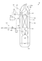
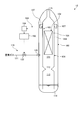
- FIG. 1 is a schematic diagram illustrating a gasifier according to the first embodiment.
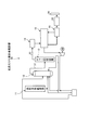
- FIG. 2 is a schematic configuration diagram of a combined coal gasification combined power generation facility to which the gasification apparatus of the first embodiment is applied.
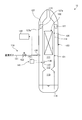
- FIG. 3 is a schematic diagram illustrating a gasifier according to the second embodiment.
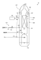
- FIG. 4 is a schematic diagram illustrating a gasifier according to a third embodiment.
- FIG. 5 is a schematic diagram illustrating a gasifier of a fourth embodiment.
- FIG. 2 is a schematic configuration diagram of a combined coal gasification combined power generation facility to which the gasification apparatus of the first embodiment is applied.
- the coal gasification combined power generation facility (IGCC: Integrated Coal Gasification Combined Cycle) of the first embodiment adopts an air combustion method in which coal gas is generated by a gasifier using air as an oxidizer and is purified by a gas purifier.
- the coal gas is supplied as fuel gas to the gas turbine equipment for power generation. That is, the coal gasification combined power generation facility of the first embodiment is an air combustion type (air blowing) power generation facility.
- the fuel supplied to the gasifier for example, a carbon-containing solid fuel such as coal is used.
- the coal gasification combined power generation facility (gasification combined power generation facility) 10 includes a pulverized coal supply facility 11, a coal gasification device 12, a char recovery device 13, and a gas purification device 14. , A combined power generation facility 15, and a waste heat recovery boiler (HRSG) 16.
- a pulverized coal supply facility 11 a coal gasification device 12, a char recovery device 13, and a gas purification device 14.
- HRSG waste heat recovery boiler
- the pulverized coal supply facility 11 is a facility for producing pulverized coal by pulverizing coal into fine particles.
- the pulverized coal produced by the pulverized coal supply facility is supplied to the coal gasifier 12.
- the coal gasifier 12 uses pulverized coal and is a device that can use char (unreacted coal and ash) recovered by the char recovery device 13.
- the coal gasifier 12 gasifies coal (pulverized coal) as a carbon-containing fuel supplied therein by partially burning it with an oxidizing agent (air, oxygen), and generates combustible gas.
- the coal gasifier 12 is provided with a gas generation line 31 for combustible gas toward the char recovery device 13 and can discharge combustible gas containing char.
- the char collection device 13 has a dust collector and a supply hopper.
- the dust collector is constituted by one or a plurality of porous filters or cyclones, and can separate char contained in the combustible gas generated by the coal gasifier 12.
- the combustible gas from which the char has been separated is sent to the gas purifier 14 through the gas discharge line 32.
- the gas purification device 14 performs gas purification by removing impurities such as sulfur compounds and nitrogen compounds from the combustible gas from which the char has been separated by the char recovery device 13.
- the gas purifier 14 purifies the combustible gas to produce fuel gas, and supplies it to the combined power generation facility 15.
- the combined power generation facility 15 includes a gas turbine facility, a steam turbine facility, and a generator.
- the exhaust heat recovery boiler 16 generates steam from the heat of the exhaust gas used in the steam turbine facility of the combined power generation facility 15 and sends the steam to the steam turbine facility.
- the exhaust gas from which heat has been recovered by the exhaust heat recovery boiler 16 is freed of harmful substances by the gas purification device 33, and the purified exhaust gas is discharged from the chimney 34 to the atmosphere.
- the pulverized coal generated by the pulverized coal supply facility 11 is supplied to the coal gasifier 12 in the coal gasification combined power generation facility 10 configured as described above. Further, the char recovered by the char recovery device 13 is supplied to the coal gasifier 12.
- the coal gasifier 12 generates combustible gas (coal gas) by burning the supplied pulverized coal and char with compressed air (oxygen) and gasifying the pulverized coal and char. This combustible gas is discharged from the coal gasifier 12 through the gas generation line 31 and sent to the char recovery device 13.
- the combustible gas is separated from the combustible gas by the dust collector, and the combustible gas from which the char has been separated is sent to the gas purification device 14 through the gas discharge line 32.
- the fine char separated from the combustible gas is returned to the coal gasifier 12 for recycling.
- the combustible gas from which the char has been separated is subjected to gas purification by removing impurities such as sulfur compounds and nitrogen compounds in the gas purification device 14 to produce fuel gas.
- gas purification by removing impurities such as sulfur compounds and nitrogen compounds in the gas purification device 14 to produce fuel gas.
- the compressed air supplied from the gas turbine facility and the fuel gas supplied from the gas purification device 14 are mixed and burned to generate combustion gas to drive the turbine.
- the exhaust gas discharged from the gas turbine equipment generates steam by exchanging heat with the feed water in the exhaust heat recovery boiler 16, and supplies the generated steam to the steam turbine equipment to rotationally drive the turbine. Then, power is generated by the generator.
- the gas purification device 33 removes harmful substances from the exhaust gas discharged from the exhaust heat recovery boiler 16, and the purified exhaust gas is released from the chimney 34 to the atmosphere.
- FIG. 1 is a schematic diagram illustrating a gasifier according to the first embodiment.
- the coal gasifier 12 is disposed above the gasifier 101 and a gasifier 101 that gasifies coal (pulverized coal) as a carbon-containing fuel. It has a heat exchanger 102 and a pressure vessel 103 for storing the gasification furnace 101, and an annulus portion (pressure holding portion) 104 is defined between the gasification furnace 101 and the pressure vessel 103.
- the gasification furnace 101 has a hollow shape, and is provided with a reductor part 111, a diffuser part 112, and a combustor part 113 from the top in the vertical direction. Further, the gasification furnace 101 is provided with a heat exchanger accommodating portion 114 for accommodating the heat exchanger 102 above the reductor portion 111 in the vertical direction, and a gas discharge port 115 is formed above the heat exchanger accommodating portion 114. Has been. At least a part of the furnace wall surface of the gasification furnace 101 is configured by a plurality of heat transfer tubes (not shown) in which the furnace wall extends in the vertical direction and is arranged in parallel in the circumferential direction.
- the pressure vessel 103 has a hollow shape, a vertical upper end is joined to the outer periphery of the gasification furnace 101, and a slag hopper 116 for storing water is provided at the lower end.
- the gasification furnace 101 is water-sealed with a lower end portion immersed in water stored in the slag hopper 116.
- an annulus portion 104 is defined in a space portion between the gasification furnace 101 and the pressure vessel 103 by arranging the gasification furnace 101 therein.
- the combustor unit 113 is a space that partially burns pulverized coal, char, and air, and the high-temperature combustion gas that burns part of the pulverized coal and char in the combustor unit 113 passes through the diffuser unit 112. It flows into the reductor unit 111.
- the reductor unit 111 is maintained at a high temperature necessary for the gasification reaction and supplies pulverized coal to the combustion gas from the combustor unit 113 to convert the pulverized coal into volatile components (carbon monoxide, hydrogen, lower hydrocarbons, etc.). It is a space that is pyrolyzed and gasified to generate a combustible gas, and the gasified combustible gas (generated gas) flows from the lower side to the upper side in the vertical direction.
- the pressure vessel 103 has an inert gas as a pressurizing gas (for example, an inert gas, carbon dioxide gas, natural gas, etc. as an inert gas) in an annulus portion 104 formed between the pressure vessel 103 and the gasification furnace 101. ) Is provided. That is, a plurality of gas nozzles 120 are provided in the circumferential direction in the pressure vessel 103, and are fixed so as to penetrate the pressure vessel 103 and have a tip portion positioned at the annulus portion 104.
- the gas nozzle 120 is provided outside the reductor unit 111 in the pressure vessel 103 and is connected to an inert gas supply line 121 as a pressurizing gas.
- the inert gas supply line 121 is provided with a flow rate adjustment valve 122.
- the heat exchanger 102 is provided inside the wall of the gasification furnace 101 and is provided vertically above the reductor unit 111.
- a plurality of heat exchangers 102 are provided along the vertical vertical direction to cool the generated gas by exchanging heat with the generated gas generated in the reductor unit 111.
- the number of heat exchangers 102 is not limited.
- the gasification furnace 101 is provided with a plurality of pressure equalizing tubes 127 communicating with the upper part in the gasification furnace 101 and the upper part of the annulus portion 104 at a predetermined interval in the circumferential direction.
- the pressure equalizing tube 127 has, for example, an L shape, one end communicates with the wall surface of the gasification furnace 101 in the vertical direction above the heat exchanger 102, and the other end opens toward the lower side of the annulus portion 104. Yes.
- the supply position of the inert gas to the annulus 104 by the gas nozzle 120 of the pressurizing gas supply device 119 is set at a position spaced apart from the pressure equalizing pipe 127 by a predetermined distance in the vertical direction.
- the “predetermined distance” is a distance at which foreign matter can be floated and discharged by the upward flow of the inert gas.
- the coal gasifier 12 maintains the high pressure state in the gasification furnace 101 by the annulus part 104 by filling the annulus part 104 between the gasification furnace 101 and the pressure vessel 103 with an inert gas. And the inside of the gasification furnace 101 and the annulus part 104 are connected by the pressure equalizing pipe 127, and the inside of the gasification furnace 101 and the exterior (annulus part 104) are equalized.
- the pressure equalizing tube 127 suppresses an increase in the differential pressure between the gasification furnace 101 and the annulus portion 104 due to the pressure fluctuation in the gasification furnace 101.
- the pressure in the gasification furnace 101 increases when the fuel supply amount changes when the load of the coal gasifier 12 increases or when the fuel supply amount changes even during rated operation, the pressure of the annulus 104 is increased. If the pressure remains lower than the pressure in the gasification furnace 101 without change, the product gas in the gasification furnace 101 flows to the annulus 104 through the pressure equalizing tube 127. The generated gas contains char, and the char flows into the annulus part 104 and may contaminate the annulus part 104.
- the coal gasifier 12 of this embodiment controls the supply amount of inert gas supplied from the gas nozzle 120 to the annulus unit 104 so that the pressure on the annulus unit 104 side is always higher than the pressure of the gasification furnace 101. ing.
- the coal gasifier 12 includes a pressure difference detection device 131 that detects a first pressure difference ⁇ P1 between the first pressure P1 inside the gasification furnace 101 of the reductor portion 111 and the second pressure P2 on the annulus portion 104 side.
- a control device 132 is provided for controlling the pressurization gas supply device 119 so that the second pressure P2 is higher than the first pressure P1 based on the detection result of the pressure difference detection device 131.
- the pressure difference detector 131 measures the pressure at the reductor unit 111 of the gasification furnace 101 below the heat exchanger 102 in the vertical direction.
- the first pressure sensor 136 that detects the first pressure P1, the second pressure sensor 137 that detects the second pressure P2, and the first pressure difference from the detected value of the first pressure sensor 136 and the detected value of the second pressure sensor 137.
- a calculation unit 138 for calculating ⁇ P1 is included.
- the first pressure sensor 136 and the second pressure sensor 137 are arranged at the same height position. That is, the first pressure sensor 136 is disposed inside the furnace wall of the gasification furnace 101.
- the second pressure sensor 137 is disposed at a position facing the first pressure sensor 136 in the annulus portion 104 in the radial direction.
- the same height is not limited to the exact same height, but a substantial difference in measured pressure in consideration of the head difference of the gas existing in the height direction, including the mounting position and mounting error. It suffices if they are arranged within a predetermined height range where no occurrence occurs.
- the calculation unit 138 receives the first pressure P1 detected by the first pressure sensor 136 and the second pressure P2 detected by the second pressure sensor 137.
- the calculation unit 138 calculates a first pressure difference ⁇ P1 obtained by subtracting the first pressure P1 from the second pressure P2.
- the control device 132 compares the first pressure difference ⁇ P1 calculated by the calculation unit 138 with a preset lower limit value PL, and determines whether or not the first pressure difference ⁇ P1 is equal to or greater than the lower limit value PL.
- This lower limit value PL is a margin (margin value) set based on a design value or a variation value obtained in advance through experiments or the like.
- the control apparatus 132 controls the gas supply apparatus 119 for a pressurization so that 1st pressure difference (DELTA) P1 becomes more than the lower limit PL.
- the amount of inert gas supplied by the pressurizing gas supply device 119 is always controlled and supplied.
- the supply amount of the inert gas by the pressurization gas supply device 119 is controlled as a total amount of the reference supply amount and the variable supply amount.
- the reference supply amount is set such that the first pressure difference ⁇ P1 is equal to or greater than a predetermined pressure difference that provides a standard pressure difference during normal rated operation.
- the reference supply amount is set by a lower limit value PL (a margin set based on a design value or a fluctuation value obtained in advance through experiments).
- the inert gas reference supply amount is supplied by the control device 132 with the inert gas reference supply amount.
- the inert gas introduced into the annulus portion 104 passes through the pressure equalizing tube 127 from the annulus portion 104 into the gasifier 101.
- the inert gas flow control is sufficiently small compared with the product gas flow rate, and no trouble occurs.
- an additional amount of inert gas supplied by the pressurizing gas supply device 119 is calculated. That is, the pressure increase rate of the second pressure P2 by the second pressure sensor 137 of the annulus unit 104 is calculated, and the state does not change from the other shapes, so the control device 132 calculates the additional variable supply amount to be supplied.
- the control device 132 adds the variable gas supply amount additionally supplied by the pressure fluctuation to the inert gas standard supply amount calculated based on the lower limit PL to the inert gas reference supply amount, and the sum of the reference supply amount and the variable supply amount is obtained.
- An appropriate amount of inert gas is supplied by the pressurizing gas supply device 119 as an amount.
- control device 132 compares the first pressure difference ⁇ P1 calculated by the calculation unit 138 with a preset upper limit value PU, and determines whether or not the first pressure difference ⁇ P1 is less than or equal to the upper limit value PU.
- This upper limit value PU is set in consideration of the strength of the furnace wall of the gasification furnace 101. That is, in designing the furnace wall of the gasification furnace 101, an upper limit value of the pressure difference between the pressure in the gasification furnace 101 and the annulus portion 104 is set, and the upper limit value of the pressure difference is the upper limit value PU.
- the control apparatus 132 controls the gas supply apparatus 119 for a pressurization so that 1st pressure difference (DELTA) P1 may become below upper limit PU.
- DELTA 1st pressure difference
- the upper limit value PU is set according to the strength of the furnace wall of the gasification furnace 101, and the pressure inside the gasification furnace and the first pressure outside the gasification furnace (annulus part) for protecting the furnace wall of the reductor part 111.
- the difference ⁇ P1 is monitored.
- the control device 132 increases the amount of inert gas supplied by the pressurizing gas supply device 119 within a range where the first pressure difference ⁇ P1 is equal to or less than the upper limit value PU.
- the inert gas is supplied to the annulus portion 104 more than necessary, the manufacturing cost of the inert gas increases, so it is desirable to supply an appropriate amount of inert gas to the annulus portion 104.
- the coal gasifier 12 further detects a second pressure difference ⁇ P2 between the third pressure P3 of the opening 127a on the gasification furnace 101 side and the fourth pressure P4 of the opening 127b on the annulus portion 104 side in the pressure equalizing pipe 127. And a control device 132 for controlling the pressurization gas supply device 119 so that the fourth pressure P4 is higher than the third pressure P3 based on the detection result of the pressure difference detection device 131. .
- the pressure difference detection device 131 further measures the pressure in the annulus portion 104 and the gasification furnace 101 in the pressure equalizing tube 127.
- the third pressure sensor 133 that detects the third pressure P3 of the gasification furnace 101, the fourth pressure sensor 134 that detects the fourth pressure P4 of the annulus 104, the detected value of the third pressure sensor 133, and the fourth pressure sensor A calculating unit 135 that calculates the second pressure difference ⁇ P2 from the detected value of 134 is provided.
- the third pressure sensor 133 and the fourth pressure sensor 134 are arranged at the same height position.
- the third pressure sensor 133 is arranged at a position vertically below the opening 127 a on the gasification furnace 101 side in the pressure equalizing tube 127 and in the radial direction through the furnace wall of the gasification furnace 101.
- the fourth pressure sensor 134 is arranged at a lower position in the vertical direction facing the opening 127b on the annulus portion 104 side of the pressure equalizing tube 127. Note that the same height is not limited to the exact same height, but a substantial difference in measured pressure in consideration of the head difference of the gas existing in the height direction, including the mounting position and mounting error. It suffices if they are arranged within a predetermined height range where no occurrence occurs.
- the calculation unit 135 receives the third pressure P3 detected by the third pressure sensor 133 and the fourth pressure P4 detected by the fourth pressure sensor 134.
- the calculating unit 135 calculates a second pressure difference ⁇ P2 obtained by subtracting the third pressure P3 from the fourth pressure P4.
- the density of the generated gas rising in the vertical direction in the gasifier 101 and the inert gas rising in the annulus 104 are different. Therefore, the first pressure difference ⁇ P1 at the arrangement position of the first and second pressure sensors 136, 137 and the second pressure difference ⁇ P2 at the arrangement position of the third and fourth pressure sensors 133, 134 are the heights thereof.
- the first pressure difference ⁇ P1 is larger than the second pressure difference ⁇ P2 because the difference between the minute, that is, the gas head difference. That is, the second pressure difference ⁇ P2 becomes smaller than the value of the first pressure difference ⁇ P1, and the product gas in the gasification furnace 101 flows to the annulus part 104 through the pressure equalizing pipe 127. Therefore, it is more preferable to monitor the second pressure difference ⁇ P2 in order to monitor and suppress the flow of the product gas through the pressure equalizing pipe 127 to the annulus section 104.
- the upper limit value PU is set according to the strength of the furnace wall of the gasification furnace 101.
- the control device 132 adds the standard supply amount of the inert gas calculated based on the lower limit value PL and the variable supply amount that is additionally supplied due to pressure fluctuation within a range in which the first pressure difference ⁇ P1 is not more than the upper limit value PU.
- the amount of inert gas supplied by the pressurizing gas supply device 119 is increased so that the amount of the inert gas is increased, and an appropriate amount of inert gas is supplied. Further, since the supply amount of the inert gas is controlled to the lower limit flow rate while controlling the upper limit flow rate, it is possible to suppress the supply of the inert gas to the annulus portion 104 more than necessary, and to suppress the increase in the manufacturing cost of the inert gas. It is desirable to supply an appropriate amount of inert gas to the annulus 104.
- the coal gasifier 12 increases the load of the gasification furnace 101 from the time of start-up and maintains a preset steady load, and reduces the load of the gasification furnace 101 to reduce the preset load.
- the operation to maintain is often performed.
- the coal gasifier 12 increases the flow rate of fuel supplied into the gasification furnace 101, but the rate of load increase at the time of startup, that is, the degree of increase in the fuel flow rate, is set in advance.
- the load reduction rate that is, the degree of decrease in the fuel flow rate may be set in advance.
- the pressure difference detection device 131 determines the predicted value of the first pressure difference ⁇ P1 or the predicted value of the second pressure difference ⁇ P2 in accordance with the load change of the gasification furnace 101 at the time of startup that is set in advance. Is estimated and set, the control device 132 adds the standard supply amount of the inert gas calculated based on the lower limit value PL and the variable supply amount that is additionally supplied in anticipation of pressure fluctuations. The amount of inert gas supplied from the pressurizing gas supply device 119 is changed in advance so that the amount of inert gas expected to be appropriate is supplied.
- control device supplies the pressurizing gas supply device such that the first pressure difference ⁇ P1 or the second pressure difference ⁇ P2 is maintained within a predetermined range, that is, between the lower limit value PL and the upper limit value PU. 119 is controlled.
- the coal gasifier 12 nitrogen and pulverized coal are charged into the gasifier 101 and ignited, and char and compressed air (oxygen) are charged and ignited. Then, in the combustor unit 113, high-temperature combustion gas is generated by the combustion of pulverized coal and char. The high-temperature combustion gas generated in the combustor unit 113 rises to the reductor unit 111 through the diffuser unit 112. In the reductor unit 111, pulverized coal is mixed with high-temperature combustion gas, and a gasification reaction is performed in a high-temperature reducing atmosphere field to generate combustible gas (coal gas).
- the pressurizing gas supply device 119 supplies the inert gas to the annulus portion 104 between the gasification furnace 101 and the pressure vessel 103 by the gas nozzle 120, and the inert gas rises upward in the vertical direction in the annulus portion 104.
- the gasifier 101 and the annulus portion 104 are provided with a pressure equalizing pipe 127 that communicates the gasifier 101 and the annulus portion 104 at the upper part thereof, the pressure in the gasifier 101 fluctuates due to a load fluctuation of the coal gasifier 12 or the like.
- the pressure equalizing pipe 127 suppresses an increase in the differential pressure between the gasification furnace 101 and the annulus portion 104.
- the coal gasifier 12 supplies a predetermined inert gas to the annulus unit 104 by the pressurization gas supply device 119, so that the pressure of the annulus unit 104 is higher than the pressure in the gasification furnace 101. Maintained.
- the pressure of the product gas rising in the gasification furnace 101 may be higher than the pressure of the annulus section 104. Then, if the pressure in the annulus 104 remains unchanged and lower than the pressure in the gasifier 101, a part of the generated gas in the gasifier 101 flows out to the annulus 104 through the pressure equalizing tube 127.
- the char contained in the generated gas may also flow out to the annulus 104.
- the first pressure sensor 136 detects the first pressure P1
- the second pressure sensor 137 detects the second pressure P2
- the calculation unit 138 detects the first pressure P1 and the second pressure.
- a first pressure difference ⁇ P1 with P2 is calculated.
- the control device 132 uses the first pressure difference ⁇ P1 calculated by the calculation unit 138 to generate the inert gas of the total amount of the fluctuation supply amount calculated from the reference supply amount necessary for maintaining the lower limit PL and the rising speed of the second pressure P2.
- the pressurization gas supply device 119 is controlled so that the amount is supplied.
- the control device 132 increases the amount of inert gas supplied to the annulus unit 104, but the first pressure difference ⁇ P1 needs to be increased to just before the upper limit value PU. If the first pressure difference ⁇ P1 exceeds the lower limit PL by a predetermined value, the increase in the amount of inert gas supplied to the annulus unit 104 may be stopped to maintain the supply amount.
- the third pressure sensor 133 detects the third pressure P3 of the gasification furnace 101
- the fourth pressure sensor 134 detects the fourth pressure P4 of the annulus unit 104
- the calculation unit 135 Calculates the second pressure difference ⁇ P2 between the third pressure P3 and the fourth pressure P4.
- the control device 132 calculates the total amount of the reference supply amount necessary for maintaining the lower limit PL and the fluctuation supply amount calculated from the rising speed of the fourth pressure P4.
- the pressurization gas supply device 119 is controlled so that the amount of inert gas is supplied.
- the second pressure difference ⁇ P2 is different in gas head difference from the first pressure difference ⁇ P1, and the second pressure difference ⁇ P2 has a pressure difference before and after the pressure equalizing tube 127 rather than the value of the first pressure difference ⁇ P1. Since it is possible to monitor with high accuracy, it is more preferable to monitor the second pressure difference ⁇ P2 because the generated gas in the gasification furnace 101 can be suppressed from flowing through the pressure equalizing pipe 127 to the annulus section 104.
- the upper limit is set such that the first pressure difference ⁇ P1 is equal to or lower than the upper limit value PU according to the strength of the furnace wall of the gasification furnace 101.
- the lower limit is defined by the standard supply amount of inert gas calculated based on the lower limit value PL by the second pressure difference ⁇ P2 and the change in pressure in order to suppress the generated gas from flowing through the pressure equalizing pipe 127 to the annulus 104.
- the supply amount of the inert gas by the pressurization gas supply device 119 is increased so as to be a total amount obtained by adding the additionally supplied variable supply amount, and an appropriate amount of inert gas is supplied. Since the inert gas supply amount is set and appropriately managed within the upper and lower limits, it is possible to suppress an increase in the production cost of the inert gas, and it is desirable to supply an appropriate amount of inert gas to the annulus section 104.
- the gasification furnace 101 is housed in the pressure vessel 103, and the annulus part 104 is defined between the two.
- the inside of the gasification furnace 101 and the annulus part 104 communicate with each other by the pressure equalizing pipe 127, and the pressurization gas
- the supply device 119 By supplying the inert gas to the annulus unit 104 by the supply device 119, the inflow of the generated gas from the gasification furnace 101 to the annulus unit 104 is suppressed.
- the pressure difference detection device 131 constantly detects the first pressure difference ⁇ P1 between the first pressure P1 in the gasification furnace 101 and the second pressure P2 in the annulus portion 104 in the reductor unit 111, and the control device 132 Based on the detection result of the pressure difference detection device 131, the pressurization gas supply device 119 is controlled so that the second pressure P2 is higher than the first pressure P1.
- the pressure difference detection device 131 constantly detects the second pressure difference ⁇ P2 between the third pressure P3 in the gasification furnace 101 and the fourth pressure P4 of the annulus 104 in the pressure equalizing pipe 127, and the control device 132 is Based on the detection result of the pressure difference detection device 131, the pressurization gas supply device 119 is controlled so that the fourth pressure P4 is higher than the third pressure P3.
- the pressurizing gas supply device 119 supplies the inert gas from the gas nozzle 120 so as to be equal to or more than the total amount obtained by adding the standard supply amount and the variable supply amount additionally supplied at the pressure increase rate. Therefore, even if the first pressure P1 or the third pressure P3 in the gasification furnace 101 is increased, the second pressure P2 or the fourth pressure P4 of the annulus portion 104 is appropriately increased further to thereby increase the gasification furnace. It is possible to suppress the generated gas in 101 from flowing into the annulus portion 104 through the pressure equalizing tube 127.
- the pressure equalizing pipe 127 is arranged above the heat exchanger 102 (for example, a economizer, a superheater, and an evaporator) in the vertical direction, and the pressure difference detection device 131 serves as the reductor unit 111.
- the control device 132 calculates a standard supply amount that is set by a lower limit PL in which the first pressure difference ⁇ P1 takes into account a margin, and a variable supply amount that is calculated from the pressure increase rate of the second pressure P2 and additionally supplied.
- the pressurization gas supply device 119 is controlled so as to be the total amount added. Therefore, by obtaining the first pressure difference ⁇ P1, even if there is a fluctuation in the pressure of the gasification furnace 101 due to a load change of the coal gasifier 12, the supply amount of the inert gas to the annulus 104 is adjusted with high accuracy. Can do.
- the first pressure sensor 136 and the second pressure sensor 137 are arranged at the same height position, and the same height position is used when the third pressure sensor 133 and the fourth pressure sensor 134 are used. Is arranged. Therefore, even if the density of the product gas in the gasification furnace 101 and the density of the inert gas in the annulus 104 are different, the first pressure sensor 136 and the second pressure sensor 137 disposed at the same height position are respectively The first pressure P1 in the gasification furnace 101 and the second pressure P2 of the annulus 104 are detected, and when the third pressure sensor 133 and the fourth pressure sensor 134 are used, the first pressure P1 in the gasification furnace 101 is used. The third pressure P3 and the fourth pressure P4 of the annulus section 104 are detected, and the detection error can be suppressed and the amount of inert gas supplied to the annulus section 104 can be adjusted with high accuracy.
- the first pressure P1 of the gasification furnace 101 is detected below the heat exchanger 102 (for example, a economizer, a superheater, and an evaporator) in the vertical direction.
- a first pressure sensor 136 that detects the second pressure P2 of the annulus 104 below the heat exchanger 102, and a first pressure difference ⁇ P1 between the first pressure P1 and the second pressure P2.
- a calculation unit 138 for calculating is provided, and the control device 132 controls the pressurization gas supply device 119 so that the first pressure difference ⁇ P1 is equal to or less than the upper limit value PU set based on the furnace wall strength of the gasification furnace 101. .
- An upper limit PU is set based on the wall strength. Therefore, by adjusting the supply amount of the inert gas to the annulus unit 104 below the upper limit value according to the first pressure difference ⁇ P1 in the region where the temperature is high in the lower part of the gasification furnace 101, the generated gas flows into the annulus unit 104 Can be suppressed, and high soundness of the gasification furnace 101 can be secured.
- the calculation unit 135 of the pressure difference detection device 131 predicts the first pressure difference ⁇ P1 according to the load change of the gasification furnace 101 at the time of preset startup or load change. And the control device 132 controls the pressurization gas supply device 119 so that the first pressure difference ⁇ P1 is maintained within a predetermined range set in advance.
- the first pressure P1 or the third pressure P3 of the gasification furnace 101 is estimated according to this fuel flow rate, The expected value of the first pressure difference ⁇ P1 or the predicted value of the second pressure difference ⁇ P2 is estimated and set, and the supply amount of inert gas at which this is equal to or higher than the lower limit value PL can be set. Therefore, the supply amount of the inert gas can be set without using the pressure sensors 133 and 134, the dispersion of the supply amount of the inert gas is suppressed due to a detection error or a detection delay, and the supply amount of the inert gas to the annulus unit 104 is increased. The accuracy can be adjusted.
- the first pressure difference between the first pressure P1 on the gasifier 101 side and the second pressure P2 on the annulus part 104 side in the reductor unit 111. ⁇ P1 is detected, and the pressurization gas supply device 119 is controlled so that the second pressure P2 is higher than the first pressure P1.
- a second pressure difference ⁇ P2 between the third pressure P3 of the opening 127a on the gasification furnace 101 side and the fourth pressure P4 of the opening 127b on the annulus portion 104 side in the pressure equalizing tube 127 is detected, and from the third pressure P3
- the pressurization gas supply device 119 is controlled so that the fourth pressure P4 is increased.
- the second pressure P2 or the fourth pressure P4 of the annulus portion 104 is further increased to increase the internal pressure of the gasification furnace 101. Can be prevented from flowing into the annulus 104 through the pressure equalizing tube 127.
- a coal gasifier 12 that gasifies coal to generate a combustible gas, and a combustible gas generated by the coal gasifier 12.
- An exhaust heat recovery boiler 19 that generates steam from the exhaust gas from the facility 15 and a steam turbine facility 17 that rotationally drives the turbine by the steam generated by the exhaust heat recovery boiler 19 are provided. Accordingly, the product gas in the gasification furnace 101 can be prevented from flowing into the annulus section 104 through the pressure equalizing pipe 127, and the efficiency of the equipment can be increased.
- FIG. 3 is a schematic diagram illustrating a gasifier according to the second embodiment.
- symbol is attached
- the coal gasifier 12 is configured such that the annulus unit 104 by the pressurization gas supply device 119 is always set so that the pressure of the annulus unit 104 is higher than the pressure of the gasification furnace 101.
- the amount of inert gas supplied to the is controlled. That is, the coal gasifier 12 estimates the second pressure difference ⁇ P2 in the vicinity of the pressure equalizing pipe 127 from the first pressure difference ⁇ P1 between the first pressure P1 of the gasification furnace 101 and the second pressure P2 of the annulus 104.
- a difference estimation device 141 and a control device 142 that controls the pressurization gas supply device 119 so that the second pressure P2 is higher than the first pressure P1 based on the estimation result of the pressure difference estimation device 141 are provided.
- the pressure difference estimation device 141 includes a first pressure sensor 136 that detects the first pressure P1 of the reductor unit 111 of the gasification furnace 101 below the heat exchanger 102 in the vertical direction, and a vertical direction below the heat exchanger 102.
- the second pressure sensor 137 that detects the second pressure P2 of the annulus 104, the second pressure sensor 127 in the vicinity of the pressure equalizing tube 127 from the detected value of the first pressure sensor, the detected value of the second pressure sensor, and the height position of the pressure equalizing tube 127.
- It has the estimation part 143 which estimates pressure difference (DELTA) P2.
- the first pressure sensor 136 and the second pressure sensor 137 are arranged at the same height in a range where no substantial difference occurs in the measured pressure.
- the estimation unit 143 receives the first pressure P1 detected by the first pressure sensor 136 and the second pressure P2 detected by the second pressure sensor 137.
- the estimation unit 143 calculates a first pressure difference ⁇ P1 obtained by subtracting the first pressure P1 from the second pressure P2, and estimates the second pressure difference ⁇ P2 from the first pressure difference ⁇ P1 and the height position of the pressure equalizing pipe 127.
- the density of the product gas rising in the gasification furnace 101 and the density of the inert gas rising in the annulus portion 104 are different. Therefore, the pressure difference between the gasification furnace 101 and the annulus 104 is different in the height position, that is, the gas head difference.
- the pressure difference estimation device 141 is located near the pressure equalizing tube 127 based on the altitude difference between the third pressure P3 of the gasifier 101, the fourth pressure P4 of the annulus 104, and the pressure equalizing tube 127 and the pressure sensors 136 and 137.
- the second pressure difference ⁇ P2 that can control the pressure difference with high accuracy can be estimated.
- the control device 142 compares the second pressure difference ⁇ P2 estimated by the estimation unit 143 with the lower limit value PL and the upper limit value PU set in advance, and the second pressure difference ⁇ P2 is equal to or higher than the lower limit value PL and the upper limit value PU. Determine if: And the control apparatus 142 controls the gas supply apparatus 119 for a pressurization so that 2nd pressure difference (DELTA) P2 is more than the lower limit PL and below the upper limit PU. Similarly to the first embodiment, the standard supply amount set by the lower limit value PU in which the second pressure difference ⁇ P2 takes into account the margin is added to the variable supply amount calculated from the pressure increase rate of the fourth pressure P4 and additionally supplied. The pressurization gas supply device 119 is controlled so as to obtain the total amount.
- DELTA 2nd pressure difference
- the pressure of the generated gas rising in the gasification furnace 101 becomes higher than the pressure of the annulus section 104 due to pressure fluctuations caused by load changes in the gasification furnace 101.
- the first pressure sensor 136 detects the first pressure P1
- the second pressure sensor 137 detects the second pressure P2
- the estimation unit 143 detects the first pressure P1 and the second pressure P2. From the pressure P2 and the height of the pressure equalizing pipe 127, the second pressure difference ⁇ P2 in the vicinity of the pressure equalizing pipe 127 is estimated.
- the control device 142 compares the second pressure difference ⁇ P2 estimated by the estimation unit 143 with the lower limit value PL, and the pressurization gas supply device 119 causes the annulus unit 104 to adjust so that the second pressure difference ⁇ P2 becomes equal to or greater than the lower limit value PL. Increase the amount of inert gas supplied. For this reason, even if the pressure in the gasification furnace 101 increases, the pressure in the annulus portion 104 also increases, and the pressure in the gasification furnace 101 does not become higher than the pressure in the annulus portion 104.
- the control device 142 compares the actually measured first pressure difference ⁇ P1 and the upper limit value PU, and the pressurizing gas supply device 119 causes the annulus unit 104 so that the first pressure difference ⁇ P1 is equal to or lower than the upper limit value PU.
- the first pressure difference ⁇ P1 between the first pressure P1 below the gasifier 101 in the vertical direction and the second pressure P2 below the annulus 104 is equalized.
- a pressure difference estimation device 141 that estimates the second pressure difference ⁇ P2 near the pressure tube 127, and a pressurization gas supply device 119 so that the fourth pressure P4 is higher than the third pressure P3 based on the estimation result of the pressure difference estimation device 141.
- a control device 142 is provided for controlling the above.
- a first pressure sensor 136 that detects the first pressure P1, a second pressure sensor 137 that detects the second pressure P2, a first pressure P1, a second pressure P2, and a pressure equalizing tube 127.
- An estimation unit 143 is provided for estimating the second pressure difference ⁇ P2 from the height position.
- the pressure sensors 136 and 137 are already provided. Therefore, the first pressure sensor 136, 137 for maintaining the strength of the gasification furnace 101 is provided without separately providing a sensor for detecting the pressure in the vicinity of the pressure equalizing pipe 127 at the upper part of the gasification furnace 101.
- FIG. 4 is a schematic diagram illustrating a gasifier according to a third embodiment.
- symbol is attached
- the coal gasifier 12 is configured such that the annulus unit 104 by the pressurization gas supply device 119 is always set so that the pressure of the annulus unit 104 is higher than the pressure of the gasification furnace 101.
- the amount of inert gas supplied to the is controlled. That is, the coal gasifier 12 includes a pressure difference estimation device 151 that estimates the first pressure difference ⁇ P1 based on the first pressure P1 of the gasifier 101 calculated from the fuel flow rate supplied to the gasifier 101, A control device 152 that controls the pressurization gas supply device 119 is provided so that the second pressure P2 is higher than the first pressure P1 based on the estimation result of the difference estimation device 151.
- the pressure difference estimation device 151 includes a first fuel flow rate sensor 153 that detects the flow rate of pulverized coal supplied to the gasification furnace 101 and a second fuel flow rate sensor 154 that detects the flow rate of char supplied to the gasification furnace 101. And an estimation unit 155 that estimates the first pressure difference ⁇ P1 from the detection value of the first fuel flow rate sensor 153 and the detection value of the second fuel flow rate sensor 154.
- the estimation unit 155 receives the flow rate of pulverized coal detected by the first fuel flow rate sensor 153 and the flow rate of char detected by the second fuel flow rate sensor 154.
- the estimation unit 155 calculates the fuel flow rate by adding the flow rate of pulverized coal and the flow rate of char, estimates the pressure of the generated gas in the gasifier 101 based on the fuel flow rate, and the pressure of the generated gas in the gasifier 101 Is used to estimate the first pressure difference ⁇ P1. Since the fuel flow rate and the gasification furnace 101 pressure increase in proportion, the relationship between the fuel flow rate and the gasification furnace 101 pressure is mapped. Further, the supply amount of the inert gas to the annulus unit 104 is uniquely set as described in the first embodiment. Therefore, the pressure difference estimation device 151 can estimate the first pressure difference ⁇ P1 from the fuel flow rate obtained by adding the pulverized coal flow rate and the char flow rate.
- the control device 152 compares the first pressure difference ⁇ P1 estimated by the estimating unit 155 with the preset lower limit value PL and upper limit value PU, and the first pressure difference ⁇ P1 is equal to or higher than the lower limit value PL and the upper limit value PU. Determine if: Then, the control device 152 controls the pressurization gas supply device 119 so that the first pressure difference ⁇ P1 is not less than the lower limit value PL and not more than the upper limit value PU. Note that the specific control of the pressurization gas supply device 119 by the control device 152 is the same as in the first and second embodiments, and thus the description thereof is omitted.
- the first pressure difference ⁇ P1 is estimated based on the first pressure of the gasifier 101 calculated from the fuel flow rate supplied to the gasifier 101.
- a pressure difference estimation device 151 and a control device 152 that controls the pressurization gas supply device 119 so that the second pressure P2 is higher than the first pressure P1 based on the estimation result of the pressure difference estimation device 151 are provided.
- the 1st fuel flow sensor 153 which detects the flow volume of the pulverized coal supplied to the gasification furnace 101, and the 2nd fuel flow volume which detects the flow volume of the char supplied to the gasification furnace 101
- a sensor 154 and an estimation unit 155 for estimating the first pressure difference ⁇ P1 from the detection value of the first fuel flow rate sensor 153 and the detection value of the second fuel flow rate sensor 154 are provided.
- the generated gas in the gasification furnace 101 is further increased through the pressure equalizing tube 127 by increasing the second pressure P2 of the annulus part 104. Inflow to 104 can be suppressed.
- fuel flow rate sensors 153 and 154 are already provided. Therefore, the annulus portion is obtained by obtaining the first pressure difference ⁇ P1 using the fuel flow sensors 153 and 154 without separately providing a sensor for detecting the pressure in the vicinity of the pressure equalizing pipe 127 at the top of the gasification furnace 101.
- the supply amount of the inert gas to 104 can be adjusted appropriately, and an increase in component costs can be prevented.
- FIG. 5 is a schematic diagram illustrating a gasifier of a fourth embodiment.
- symbol is attached
- the coal gasifier 12 is configured such that the annulus unit 104 by the pressurization gas supply device 119 is always set so that the pressure of the annulus unit 104 is higher than the pressure of the gasification furnace 101.
- the amount of inert gas supplied to the is controlled. That is, the coal gasifier 12 calculates a pressure difference estimation device 161 that calculates a pressure increase rate in the furnace of the gasifier 101 based on the pressure of the gasifier 101 and estimates the first pressure difference ⁇ P1, and a pressure difference estimator.
- a control device 162 that controls the pressurization gas supply device 119 is provided so that the second pressure P2 is higher than the first pressure P1 based on the estimation result of the device 161.
- the pressure difference estimation device 161 includes a pressure sensor 163 that detects the pressure in the gasification furnace 101, and an estimation unit 164 that estimates the first pressure difference ⁇ P1 from the detection value of the pressure sensor 163.
- the pressure sensor 163 detects the pressure of the gasifier 101 having the same height as the opening of the pressure equalizing tube 127 on the annulus portion 104 side.
- the estimation unit 164 detects the pressure of the gasification furnace 101 in the vicinity of the pressure equalizing pipe 127 detected by the pressure sensor 163, calculates the in-furnace pressure increase rate of the gasification furnace 101 based on the pressure of the gasification furnace 101, The first pressure difference ⁇ P1 is estimated based on the furnace pressure increase rate.
- the coal gasifier 12 raises the load of the gasification furnace 101 to maintain a preset steady load from the time of startup, and reduces the load of the gasification furnace 101 to reduce the preset load.
- the operation to maintain is often performed.
- the coal gasifier 12 increases the flow rate of the fuel supplied into the gasification furnace 101, but the rate of increase in load at the time of start-up, that is, the degree of increase in the fuel flow rate, is set in advance. .
- the load reduction rate that is, the degree of decrease in the fuel flow rate
- the operating condition of the gasification furnace 101 is estimated based on the pressure increase rate of the gasification furnace 101, The pressure situation can be estimated.
- the pressure of the gasification furnace 101 is detected by the pressure sensor 163, and the predicted value of the first pressure difference ⁇ P1 or the prediction of the second pressure difference ⁇ P2 according to the load change of the gasification furnace 101 during a preset load operation.
- the value can be estimated and set.
- the control device 162 compares the first pressure difference ⁇ P1 estimated by the estimating unit 164 with the lower limit value PL and the upper limit value PU set in advance, and the first pressure difference ⁇ P1 is equal to or higher than the lower limit value PL and the upper limit value PU. Determine if: Then, the control device 162 controls the pressurization gas supply device 119 so that the first pressure difference ⁇ P1 is not less than the lower limit value PL and not more than the upper limit value PU. Note that the specific control of the pressurization gas supply device 119 by the control device 162 is the same as in the first and second embodiments, and thus the description thereof is omitted.
- the pressure difference estimation for estimating the first pressure difference ⁇ P1 by calculating the in-furnace pressure increase rate of the gasification furnace 101 based on the pressure of the gasification furnace 101 is provided.
- An apparatus 161 and a control apparatus 162 that controls the pressurization gas supply apparatus 119 so that the second pressure P2 is higher than the first pressure P1 based on the estimation result of the pressure difference estimation apparatus 161 are provided.
- a pressure sensor 163 that detects the pressure of the gasification furnace 101, and a furnace pressure increase rate of the gasification furnace 101 is calculated based on a detection value of the pressure sensor 163 to calculate the first pressure difference.
- An estimation unit 164 that estimates ⁇ P1 is provided.
- the generated gas in the gasification furnace 101 is further increased through the pressure equalizing tube 127 by increasing the second pressure P2 of the annulus part 104. Inflow to 104 can be suppressed.
- a pressure sensor 163 for detecting the pressure in the upper part of the gasification furnace 101 is provided. Therefore, only one sensor for detecting the pressure in the vicinity of the pressure equalizing pipe 127 in the upper part of the gasification furnace 101 may be used. By obtaining the first pressure difference ⁇ P1 using the pressure sensor 163, the sensor for the annulus unit 104 is obtained. The supply amount of the inert gas can be adjusted appropriately, and an increase in parts cost can be prevented.
- the pressure sensor is provided in the vicinity of the pressure equalizing tube or below the heat exchanger to detect the pressure of the gasifier, but the position to be arranged is not limited to this height, What is necessary is just to set suitably.
- the pressure equalizing tube is not limited to the L-shaped one, and may be a cylindrical pressure equalizing tube.
- coal is used as a fuel.
- it can be applied to high-grade coal or low-grade coal, and is not limited to coal, but can be used as a renewable biological organic resource.
- it is also possible to use thinned wood, waste wood, driftwood, grass, waste, sludge, tires, and recycled fuel (pellets and chips) made from these raw materials. .
- the lower part of the gasification furnace and the lower part of the annulus part are sealed with hopper water, and when the differential pressure between the gasification furnace and the annulus part increases, the hopper water flows into the gasification furnace. By cutting the seal, the strength of the gasifier furnace wall can be secured.
- the present invention is not intended for this point, and suppresses the product gas in the gasification furnace from flowing into the pressure holding section through the pressure equalizing pipe.
Landscapes
- Chemical & Material Sciences (AREA)
- Engineering & Computer Science (AREA)
- Combustion & Propulsion (AREA)
- Oil, Petroleum & Natural Gas (AREA)
- Organic Chemistry (AREA)
- Mechanical Engineering (AREA)
- General Engineering & Computer Science (AREA)
- Engine Equipment That Uses Special Cycles (AREA)
- Processing Of Solid Wastes (AREA)
- Gasification And Melting Of Waste (AREA)
Abstract
ガス化装置、ガス化装置の制御装置及び方法、ガス化複合発電設備において、ガス化炉(101)と、圧力容器(102)と、ガス化炉(101)と圧力容器(102)との間にイナートガスが充填されるアニュラス部(104)と、アニュラス部(104)にイナートガスを供給する加圧用ガス供給装置(119)と、ガス化炉(101)の内部とアニュラス部(104)とを連通する均圧管(127)と、リダクタ部(111)における第1圧力差(ΔP1)を検出する圧力差検出装置(131)と、均圧管(127)における第2圧力差(ΔP2)を検出する圧力差検出装置(131)と、圧力差検出装置(131)の検出結果に基づいて第1圧力差(ΔP1)もしくは、第2圧力差(ΔP2)を用いて、生成ガスが均圧管(127)を通ってアニュラス部(104)への流れ出しを抑制するように加圧用ガス供給装置(119)を制御する制御装置(132)を設ける。
Description
本発明は、石炭やバイオマスなどの炭素含有固体燃料を部分燃焼させてガス化することでガス燃料を生成するガス化装置、このガス化装置の制御装置及び方法、ガス化装置を備えたガス化複合発電設備に関するものである。
ガス化複合発電設備(石炭ガス化複合発電設備)は、給炭装置、石炭ガス化装置、ガス精製装置、ガスタービン設備、蒸気タービン設備、排熱回収ボイラ、ガス浄化装置などにより構成されている。この石炭ガス化複合発電設備における石炭ガス化装置は、圧力容器内にガス化炉が配置され、このガス化炉の鉛直下方に燃焼装置が配置される一方、鉛直上方に熱交換器(ガス冷却器)が配置されて構成されている。また、石炭ガス化装置は、圧力容器とガス化炉との間のアニュラス部(圧力保持部)に窒素などの不活性ガスを充填することで、ガス化炉内を高圧状態に維持している。そして、ガス化炉内とアニュラス部とが均圧管により連通することで、ガス化炉内の圧力変動に伴うガス化炉内とアニュラス部との差圧の上昇を抑制している。このような石炭ガス化装置として、例えば、下記特許文献1,2に記載されたものがある。
石炭ガス化装置は、負荷上昇時に燃料の供給量が変動し、ガス化炉内の圧力が上昇と、ガス化炉内の生成ガスが均圧管を通ってアニュラス部へと流れることでガス化炉内とアニュラス部との差圧の上昇を抑制している。アニュラス部は、アニュラス部の圧力を維持するために窒素などの不活性ガスによる加圧用ガスを供給することで、ガス化炉からアニュラス部へと流れ出た生成ガスは、ガス化炉内へと戻されてアニュラス部は不活性ガス雰囲気を維持することができる。一方、この生成ガスは、未反応分及び灰分(以下、チャーと呼ぶ。)を含んでおり、このチャーが生成ガスとともにアニュラス部に流れ込む場合がある。石炭ガス化装置は、下端部に水を貯留するスラグホッパが設けられており、アニュラス部に流れ込んだチャーがアニュラス部を汚す恐れがある。
本発明は、上述した課題を解決するものであり、ガス化炉内の圧力変動に対する生成ガスの均圧管を通したアニュラス部(圧力保持部)への流れ込みを抑制可能とするガス化装置、ガス化装置の制御装置及び方法、ガス化複合発電設備を提供することを目的とする。
上記の目的を達成するための本発明のガス化装置は、炭素含有燃料のガス化を行うガス化炉と、前記ガス化炉を格納する圧力容器と、前記ガス化炉と前記圧力容器との間に加圧用ガスが充填される圧力保持部と、前記圧力保持部に加圧用ガスを供給する加圧用ガス供給装置と、前記ガス化炉の内部と前記圧力保持部とを連通する均圧管と、前記ガス化炉側の第1圧力と前記圧力保持部側の第2圧力との第1圧力差を検出または推定する圧力差検出推定装置と、前記圧力差検出推定装置の検出結果または推定結果に基づいて前記第1圧力より前記第2圧力が高くなるように前記加圧用ガス供給装置を制御する制御装置と、を備えることを特徴とするものである。
従って、圧力容器内にガス化炉が格納され、両者の間に圧力保持部が区画されており、ガス化炉の内部と圧力保持部とが均圧管により連通し、加圧用ガス供給装置が圧力保持部に加圧用ガスを供給することで、ガス化炉から圧力保持部への生成ガスの流入を抑制している。ところが、ガス化炉内での圧力変動によりガス化炉内の圧力が上昇し、圧力保持部より高くなることがある。圧力差検出推定装置は、ガス化炉側の第1圧力と圧力保持部側の第2圧力との第1圧力差を検出または推定している。制御装置は、圧力差検出推定装置の検出結果または推定結果に基づいて第1圧力より第2圧力が高くなるように加圧用ガス供給装置を制御する。そのため、ガス化炉内の圧力が上昇しても、それ以上に圧力保持部の圧力を上昇させることで、ガス化炉内の生成ガスが均圧管を通して圧力保持部へ流れ込むことを抑制することができる。
本発明のガス化装置では、前記圧力差検出推定装置は、前記均圧管よりガス流れ方向に離間して前記ガス化炉の第1圧力を検出する第1圧力センサと、前記均圧管よりガス流れ方向に離間して前記圧力保持部の第2圧力を検出する第2圧力センサと、前記第1圧力センサの検出値と前記第2圧力センサの検出値とから前記第1圧力差を算出する算出部を有することを特徴としている。
従って、均圧管より離間した第1圧力センサと第2圧力センサを用いることで、容易に第1圧力差を算出することができる。そして、ガス化炉内における生成ガスの密度と圧力保持部における加圧用ガスの密度が相違する場合、下方ほどその圧力差が大きくなることから、ガス化炉の炉壁強度を確保するために、均圧管より離間した第1圧力センサと第2圧力センサを用いて、ガス化炉内と圧力保持部の差圧を監視している。この第1圧力センサと第2圧力センサを用いてガス化炉内と圧力保持部の差圧を検出することで、容易に第1圧力差を算出することができる。
本発明のガス化装置では、前記圧力差検出推定装置は、前記均圧管における前記ガス化炉側の開口部の第3圧力と前記圧力保持部側の開口部の第4圧力との第2圧力差を検出または推定し、前記制御装置は、前記圧力差検出推定装置)の検出結果または推定結果に基づいて前記第3圧力より前記第4圧力が高くなるように前記加圧用ガス供給装置を制御することを特徴としている。
従って、ガス化炉側の均圧管の開口部の第3圧力と圧力保持部側の均圧管の開口部の第4圧力を用いることから、第2圧力差を高精度に検出または推定することができ、ガス化炉内の生成ガスが均圧管を通して圧力保持部へ流れ込むことを抑制することができる。
本発明のガス化装置では、前記ガス化炉の鉛直方向上部に熱交換器が配置され、前記均圧管は、前記熱交換器より鉛直方向の上方に配置され、前記圧力差検出推定装置は、前記第3圧力を検出する第3圧力センサと、前記第4圧力を検出する第4圧力センサと、前記第3圧力センサの検出値と前記第4圧力センサの検出値から前記第2圧力差を算出する算出部を有し、前記制御装置は、前記第2圧力差が予め設定された余裕度を加味した下限値以上となるように前記加圧用ガス供給装置を制御することを特徴としている。
従って、算出部は、第3圧力センサの検出値と第4圧力センサの検出値から第2圧力差を算出し、制御装置は、第2圧力差が下限値以上となるように加圧用ガス供給装置による圧力保持部への加圧用ガスの供給量を調整している。そのため、ガス化炉の上部にある均圧管の近傍の圧力をセンサにより直接検出して第1圧力差を求めることで、圧力保持部への加圧用ガスの供給量を高精度に調整することができる。
本発明のガス化装置では、加圧用ガスの供給量は、基準供給量と変動供給量の合計量として制御され、基準供給量は、第1圧力差が通常の定格運転時の標準時の圧力差が得られる所定の圧力差以上となるように設定され、前記制御装置は、前記圧力保持部の第2圧力センサによる第2圧力の圧力上昇速度により追加で供給する変動供給量を算出することを特徴としている。
従って、加圧用ガスの供給量が定格運転時の基準供給量と追加で供給する変動供給量の合計量とすることで、圧力保持部の圧力をガス化炉内の圧力よりも容易に高く維持することができる。また、均圧管付近の第2圧力の上昇速度により追加で供給する変動供給量を算出することで、より高精度に圧力保持部の圧力をガス化炉内の圧力よりも高く維持することができ、炉内から圧力保持部へのガス流れを適切に防止することができるため、圧力保持部の汚れを防ぐことが可能となる。
本発明のガス化装置では、前記第1圧力センサと前記第2圧力センサは、同じ高さ位置に配置されることを特徴としている。
従って、ガス化炉内における生成ガスの密度と圧力保持部における加圧用ガスの密度が相違する場合であっても、同じ高さ位置に配置される第1圧力センサと第2圧力センサがそれぞれガス化炉内の圧力と圧力保持部の圧力を検出することとなり、検出誤差を抑制して圧力保持部への加圧用ガスの供給量を高精度に調整することができる。
本発明のガス化装置では、前記加圧用ガス供給装置による前記圧力保持部への加圧用ガスの供給位置は、前記均圧管から所定距離だけ鉛直方向の下方に離間した位置に設けられることを特徴としている。
従って、圧力保持部への加圧用ガスの供給位置が均圧管から下方に離間した位置に設けられることで、加圧用ガスが圧力保持部内を均圧管側へ上昇する流れとなり、ガス化炉側の異物が均圧管を通して圧力保持部に移動しても、加圧用ガスの上方流れにより異物浮遊排出させることができる。
本発明のガス化装置では、前記圧力差検出推定装置は、前記均圧管よりガス流れ方向に離間して前記ガス化炉の第1圧力を検出する第1圧力センサと、前記均圧管よりガス流れ方向に離間して前記圧力保持部の第2圧力を検出する第2圧力センサと、前記第1圧力センサの検出値と前記第2圧力センサの検出値とから第2圧力差を算出する算出部を有し、前記制御装置は、前記第2圧力差が前記ガス化炉の炉壁強度に基づいて設定された上限値以下となるように前記加圧用ガス供給装置を制御することを特徴としている。
従って、算出部は、第1圧力センサが検出した第1圧力と、第2圧力センサが検出した第2圧力から第2圧力差を算出し、制御装置は、第2圧力差が上限値以下となるように加圧用ガス供給装置による圧力保持部への加圧用ガスの供給量を調整している。ガス化炉内における生成ガスの密度と圧力保持部における加圧用ガスの密度が相違する場合、下方ほどその圧力差が大きくなることから、ガス化炉の炉壁強度に基づいて上限値が設定される。そのため、ガス化炉の下部における第2圧力差に応じて圧力保持部への加圧用ガスの供給量を調整することで、圧力保持部への生成ガスの流れ込みを抑制することができると共に、ガス化炉の高い健全性を確保することができる。
本発明のガス化装置では、前記圧力差検出推定装置は、第1圧力を検出する第1圧力センサと、前記圧力保持部の下部の第2圧力を検出する第2圧力センサと、前記第1圧力センサの検出値と前記第2圧力センサの検出値と前記均圧管の高さ位置とから前記第2圧力差を推定する推定部を有し、前記制御装置は、前記第2圧力差が予め設定された所定の範囲内に維持されるように前記加圧用ガス供給装置を制御することを特徴としている。
従って、推定部は、第1圧力センサが検出した第1圧力と、第2圧力センサが検出した第2圧力と、均圧管の高さ位置とから第2圧力差を推定し、制御装置は、第2圧力差が所定の範囲内に維持されるように加圧用ガス供給装置による圧力保持部への加圧用ガスの供給量を調整している。そのため、ガス化炉の上部にある均圧管の近傍の圧力を検出するためのセンサを別途設けることなく、ガス化炉の強度を維持するためのセンサを用いて第1圧力差を求めることで、圧力保持部への加圧用ガスの供給量を適正に調整することができると共に、部品コストの増加を防止することができる。
本発明のガス化装置では、前記圧力差検出推定装置は、前記ガス化炉に供給される燃料流量を検出する燃料流量センサと、前記燃料流量センサの検出値に基づいて前記ガス化炉の圧力を推定して前記第1圧力差を推定する推定部を有し、前記制御装置は、前記第1圧力差が予め設定された所定の範囲内に維持されるように前記加圧用ガス供給装置を制御することを特徴としている。
従って、推定部は、燃料流量センサが検出したガス化炉に供給される燃料流量に基づいて第1圧力差を推定し、制御装置は、第1圧力差が所定の範囲内に維持されるように加圧用ガス供給装置による圧力保持部への加圧用ガスの供給量を調整している。そのため、ガス化炉の上部にある均圧管の近傍の圧力を検出するためのセンサを別途設けることなく、ガス化炉に供給される燃料流量を検出するためのセンサを用いて第1圧力差を求めることで、圧力保持部への加圧用ガスの供給量を適正に調整することができると共に、部品コストの増加を防止することができる。
本発明のガス化装置では、前記圧力差検出推定装置は、前記ガス化炉の圧力を検出する圧力センサと、前記圧力センサの検出値に基づいて前記ガス化炉の炉内圧力上昇速度を算出して前記第1圧力差を推定する推定部を有し、前記制御装置は、前記第1圧力差が予め設定された所定の範囲内に維持されるように前記加圧用ガス供給装置を制御することを特徴としている。
従って、推定部は、圧力センサが検出したガス化炉の圧力に基づいて第1圧力差を推定し、制御装置は、第1圧力差が所定の範囲内に維持されるように加圧用ガス供給装置による圧力保持部への加圧用ガスの供給量を調整している。そのため、ガス化炉の上部にある均圧管の近傍の圧力を検出するためのセンサを別途設けることなく、ガス化炉の圧力を検出するためのセンサを用いて第1圧力差を求めることで、圧力保持部への加圧用ガスの供給量を適正に調整することができると共に、部品コストの増加を防止することができる。
本発明のガス化装置では、前記圧力差検出推定装置は、予め設定された起動時における前記ガス化炉の負荷変化に応じて前記第1圧力差を算出する算出部を有し、前記制御装置は、前記第1圧力差が予め設定された所定の範囲内に維持されるように前記加圧用ガス供給装置を制御することを特徴としている。
従って、算出部は、起動時におけるガス化炉の負荷上昇に応じて第1圧力差を算出し、制御装置は、第1圧力差が所定の範囲内に維持されるように加圧用ガス供給装置による圧力保持部への加圧用ガスの供給量を調整している。そのため、圧力センサを用いることなく加圧用ガスの供給量を設定することができ、検出誤差や検出遅れなどにより加圧用ガスの供給量のばらつきを抑制し、圧力保持部への加圧用ガスの供給量を高精度に調整することができる。
本発明のガス化装置の制御装置は、炭素含有燃料のガス化を行うガス化炉と、前記ガス化炉を格納する圧力容器と、前記ガス化炉と前記圧力容器との間に加圧用ガスが充填される圧力保持部と、前記圧力保持部に加圧用ガスを供給する加圧用ガス供給装置と、前記ガス化炉の内部と前記圧力保持部とを連通する均圧管と、を備えるガス化装置において、前記ガス化炉側の第1圧力より前記圧力保持部側の第2圧力が高くなるように前記加圧用ガス供給装置を制御する、ことを特徴とするものである。
従って、圧力差検出推定装置の検出結果または推定結果に基づいて第1圧力より第2圧力が高くなるように加圧用ガス供給装置を制御するため、ガス化炉内の圧力が上昇しても、それ以上に圧力保持部の圧力を上昇させることで、ガス化炉内の生成ガスが均圧管を通して圧力保持部へ流れ込むことを抑制することができる。
本発明のガス化装置の制御方法は、炭素含有燃料のガス化を行うガス化炉と、前記ガス化炉を格納する圧力容器と、前記ガス化炉と前記圧力容器との間に加圧用ガスが充填される圧力保持部と、前記圧力保持部に加圧用ガスを供給する加圧用ガス供給装置と、前記ガス化炉の内部と前記圧力保持部とを連通する均圧管と、を備えるガス化装置において、前記ガス化炉側の第1圧力と前記圧力保持部側の第2圧力との第1圧力差を検出または推定する工程と、前記第1圧力より前記第2圧力が高くなるように前記加圧用ガス供給装置を制御する工程と、を有することを特徴とするものである。
従って、ガス化炉内の圧力が上昇しても、それ以上に圧力保持部の圧力を上昇させることで、ガス化炉内の生成ガスが均圧管を通して圧力保持部へ流れ込むことを抑制することができる。
本発明のガス化複合発電設備は、炭素含有固体燃料をガス化して可燃性ガスを生成する前記ガス化装置と、前記ガス化装置により生成された可燃性ガスから不純物を取り除くことでガス精製を行うガス精製装置と、前記ガス精製装置によりガス精製された可燃性ガスの少なくとも一部と圧縮空気との混合ガスを燃焼してタービンを駆動するガスタービン設備と、前記ガスタービン設備からの排ガスにより蒸気を生成する排熱回収ボイラと、前記排熱回収ボイラにより生成された蒸気によりタービンを駆動する蒸気タービン設備と、を備えることを特徴とするものである。
従って、ガス化装置にて、圧力差検出推定装置の検出結果または推定結果に基づいて第1圧力より第2圧力が高くなるように加圧用ガス供給装置を制御するため、ガス化炉内の圧力が上昇しても、それ以上に圧力保持部の圧力を上昇させることで、ガス化炉内の生成ガスが均圧管を通して圧力保持部へ流れ込むことを抑制することができる。その結果、圧力保持部でのチャーの落下を防止してアニュラス部が汚れることを防止できる。
本発明のガス化装置、ガス化装置の制御装置及び方法、ガス化複合発電設備によれば、ガス化炉内の圧力変動に対して均圧管におけるガス化炉側の開口部の第1圧力より圧力保持部側の開口部の第2圧力が高くなるように加圧用ガス供給装置を制御するので、ガス化炉内の生成ガスが均圧管を通して圧力保持部へ流れ込むことを抑制することができる。
以下に添付図面を参照して、本発明に係るガス化装置、ガス化装置の制御装置及び方法、ガス化複合発電設備の好適な実施形態を詳細に説明する。なお、この実施形態により本発明が限定されるものではなく、また、実施形態が複数ある場合には、各実施形態を組み合わせて構成するものも含むものである。
[第1実施形態]
図2は、第1実施形態のガス化装置が適用された石炭ガス化複合発電設備の概略構成図である。
図2は、第1実施形態のガス化装置が適用された石炭ガス化複合発電設備の概略構成図である。
第1実施形態の石炭ガス化複合発電設備(IGCC:Integrated Coal Gasification Combined Cycle)は、空気を酸化剤としてガス化装置で石炭ガスを生成する空気燃焼方式を採用し、ガス精製装置で精製した後の石炭ガスを燃料ガスとしてガスタービン設備に供給して発電を行っている。即ち、第1実施形態の石炭ガス化複合発電設備は、空気燃焼方式(空気吹き)の発電設備である。ガス化装置に供給する燃料としては、例えば、石炭等の炭素含有固体燃料が用いられる。
第1実施形態において、図2に示すように、石炭ガス化複合発電設備(ガス化複合発電設備)10は、微粉炭供給設備11、石炭ガス化装置12、チャー回収装置13、ガス精製装置14、複合発電設備15、排熱回収ボイラ(HRSG:Heat Recovery Steam Generator)16を備えている。
微粉炭供給設備11は、石炭を細かい粒子状に粉砕して、微粉炭を製造する設備である。微粉炭供給設備によって製造された微粉炭は、石炭ガス化装置12へ供給される。石炭ガス化装置12は、微粉炭を利用すると共に、チャー回収装置13で回収されたチャー(石炭の未反応分及び灰分)を利用できる装置となっている。石炭ガス化装置12は、内部に供給された炭素含有燃料しての石炭(微粉炭)を酸化剤(空気、酸素)により部分燃焼させることでガス化させ、可燃性ガスを生成する。この石炭ガス化装置12は、チャー回収装置13に向けて可燃性ガスのガス生成ライン31が設けられており、チャーを含む可燃性ガスが排出可能となっている。
チャー回収装置13は、集塵装置と供給ホッパとを有している。この場合、集塵装置は、1つまたは複数のポーラスフィルタやサイクロンにより構成され、石炭ガス化装置12で生成された可燃性ガスに含有するチャーを分離することができる。そして、チャーが分離された可燃性ガスは、ガス排出ライン32を通してガス精製装置14に送られる。
ガス精製装置14は、チャー回収装置13によりチャーが分離された可燃性ガスに対して、硫黄化合物や窒素化合物などの不純物を取り除くことで、ガス精製を行うものである。そして、ガス精製装置14は、可燃性ガスを精製して燃料ガスを製造し、これを複合発電設備15に供給する。
複合発電設備15は、ガスタービン設備と蒸気タービン設備と発電機から構成されている。排熱回収ボイラ16は、複合発電設備15の蒸気タービン設備で使用された排気ガスの熱により蒸気を生成して蒸気タービン設備に送る。そして、排熱回収ボイラ16で熱が回収された排ガスは、ガス浄化装置33により有害物質を除去され、浄化された排ガスは、煙突34から大気へ放出される。
このように構成された石炭ガス化複合発電設備10にて、微粉炭供給設備11によって生成された微粉炭が石炭ガス化装置12に供給される。また、チャー回収装置13で回収されたチャーが、石炭ガス化装置12に供給される。石炭ガス化装置12は、供給された微粉炭及びチャーが圧縮空気(酸素)により燃焼し、微粉炭及びチャーがガス化することで、可燃性ガス(石炭ガス)を生成する。そして、この可燃性ガスは、石炭ガス化装置12からガス生成ライン31を通して排出され、チャー回収装置13に送られる。チャー回収装置13にて、可燃性ガスは、集塵装置により可燃性ガスからチャーが分離され、チャーが分離された可燃性ガスは、ガス排出ライン32を通してガス精製装置14に送られる。一方、可燃性ガスから分離した微粒チャーは、石炭ガス化装置12に戻されてリサイクルされる。
チャーが分離された可燃性ガスは、ガス精製装置14にて、硫黄化合物や窒素化合物などの不純物が取り除かれてガス精製され、燃料ガスが製造される。そして、複合発電設備15では、ガスタービン設備から供給される圧縮空気とガス精製装置14から供給される燃料ガスとを混合し、燃焼することで燃焼ガスを生成してタービンを駆動し、発電機により発電を行う。そして、ガスタービン設備から排出された排気ガスは、排熱回収ボイラ16にて、給水と熱交換を行うことで蒸気を生成し、この生成した蒸気を蒸気タービン設備に供給してタービンを回転駆動し、発電機により発電を行う。ガス浄化装置33は、排熱回収ボイラ16から排出された排気ガスの有害物質を除去し、浄化された排ガスが煙突34から大気へ放出される。
以下、上述した石炭ガス化複合発電設備10における石炭ガス化装置12について詳細に説明する。図1は、第1実施形態のガス化装置を表す概略図である。
本実施形態では、石炭ガス化装置12は、図1に示すように、炭素含有燃料としての石炭(微粉炭)のガス化を行うガス化炉101と、ガス化炉101の上方に配置される熱交換器102と、ガス化炉101を格納する圧力容器103とを有しており、ガス化炉101と圧力容器103との間にアニュラス部(圧力保持部)104が区画されている。
ガス化炉101は、中空形状をなし、鉛直方向の上部からリダクタ部111、ディフューザ部112、コンバスタ部113が設けられている。また、このガス化炉101は、リダクタ部111の鉛直方向の上方に熱交換器102を収容する熱交換器収容部114が設けられ、熱交換器収容部114の上方にガス排出口115が形成されている。このガス化炉101の炉壁面の少なくとも一部は、炉壁が鉛直方向に延びて周方向に並設される複数の伝熱管(図示せず)により構成されている。
圧力容器103は、中空形状をなし、鉛直方向の上端部がガス化炉101の外周部に接合され、下端部に水を貯留するスラグホッパ116が設けられている。ガス化炉101は、下端部がスラグホッパ116の貯留水に浸水して水封されている。この圧力容器103は、内部にガス化炉101が配置されることで、ガス化炉101と圧力容器103との空間部にアニュラス部104が区画されている。
コンバスタ部113は、微粉炭及びチャーと空気とを一部燃焼させる空間となっており、コンバスタ部113で微粉炭及びチャーの一部を燃焼した高温の燃焼ガスは、ディフューザ部112を通過してリダクタ部111に流入する。リダクタ部111は、ガス化反応に必要な高温状態に維持されコンバスタ部113からの燃焼ガスに微粉炭を供給して、微粉炭を揮発分(一酸化炭素、水素、低級炭化水素等)へと熱分解してガス化されて可燃性ガスを生成する空間となっており、ガス化した可燃性ガス(生成ガス)が鉛直方向の下方側から上方側に向かって流通する。
また、圧力容器103は、この圧力容器103とガス化炉101との間に形成されるアニュラス部104に加圧用ガスとしてのイナートガス(例えば、不活性ガスとしてのイナートガス、二酸化炭素ガス、天然ガスなど)を供給する加圧用ガス供給装置119が設けられている。即ち、ガスノズル120は、圧力容器103に周方向に複数設けられ、この圧力容器103を貫通して先端部がアニュラス部104に位置するように固定されている。このガスノズル120は、圧力容器103におけるリダクタ部111の外側に設けられており、加圧用ガスとしてのイナートガス供給ライン121が接続されている。イナートガス供給ライン121は、流量調整弁122が設けられている。イナートガスがガスノズル120によりアニュラス部104の下部に供給されると、このナートガスがアニュラス部104内を上昇して全領域に充満される。
熱交換器102は、ガス化炉101の壁面の内部に設けられると共に、リダクタ部111鉛直上方側に設けられている。また、熱交換器102は、鉛直上下方向に沿って複数設けられリダクタ部111において生成された生成ガスと熱交換を行うことで、生成ガスを冷却する。なお、熱交換器102の数量を限定するものではない。
ガス化炉101は、ガス化炉101内の上部とアニュラス部104の上部とを連通する均圧管127が周方向に所定間隔で複数設けられている。均圧管127は、例えばL字形状をなし、一端部が熱交換器102より鉛直方向の上方のガス化炉101の壁面に連通し、他端部がアニュラス部104の下方を向いて開口している。なお、加圧用ガス供給装置119のガスノズル120によるアニュラス部104へのイナートガスの供給位置は、均圧管127から所定距離だけ鉛直方向の下方に離間した位置に設定されている。ここで、所定距離」とは、イナートガスの上方流れにより異物を浮遊排出させることが可能な距離である。
石炭ガス化装置12は、ガス化炉101と圧力容器103との間のアニュラス部104にイナートガスを充填することで、ガス化炉101内の高圧状態をアニュラス部104により維持している。そして、ガス化炉101内とアニュラス部104とが均圧管127により連通することで、ガス化炉101の内部と外部(アニュラス部104)とを均圧にしている。均圧管127により、ガス化炉101内の圧力変動に伴うガス化炉101内とアニュラス部104との差圧の上昇を抑制している。
ところが、石炭ガス化装置12の負荷上昇時の燃料の供給量の変動や、定格運転中でも燃料供給量が変動した場合には、ガス化炉101内の圧力が上昇するため、アニュラス部104の圧力が変わらずにガス化炉101内の圧力よりも低いままであれば、ガス化炉101内の生成ガスが均圧管127を通ってアニュラス部104へ流れる。この生成ガスは、チャーを含んでおり、このチャーがアニュラス部104に流れ込み、アニュラス部104を汚す可能性がある。
そこで、本実施形態の石炭ガス化装置12は、常時、ガス化炉101の圧力よりアニュラス部104側の圧力が高くなるように、ガスノズル120からアニュラス部104に供給するイナートガスの供給量を制御している。
即ち、石炭ガス化装置12は、リダクタ部111のガス化炉101の内側の第1圧力P1とアニュラス部104側の第2圧力P2との第1圧力差ΔP1を検出する圧力差検出装置131と、圧力差検出装置131の検出結果に基づいて第1圧力P1より第2圧力P2が高くなるように加圧用ガス供給装置119を制御する制御装置132が設けられている。
圧力差検出装置131は、熱交換器102より鉛直方向の下方でガス化炉101のリダクタ部111で、圧力を計測する。第1圧力P1を検出する第1圧力センサ136と、第2圧力P2を検出する第2圧力センサ137と、第1圧力センサ136の検出値と第2圧力センサ137の検出値から第1圧力差ΔP1を算出する算出部138を有している。この場合、第1圧力センサ136と第2圧力センサ137は、同じ高さ位置に配置されている。即ち、第1圧力センサ136は、ガス化炉101の炉壁内部に配置されている。一方、第2圧力センサ137は、アニュラス部104で、第1圧力センサ136と径方向に対向する位置に配置されている。なお、同じ高さとは、全く同一高さに限定されるものではなく、取付け位置や取付け誤差などを含めて高さ方向に存在する気体のヘッド差を考慮して、計測圧力に実質的な差異が生じない所定の高さ範囲内に配置されていればよい。
算出部138は、第1圧力センサ136が検出した第1圧力P1と、第2圧力センサ137が検出した第2圧力P2が入力される。算出部138は、第2圧力P2から第1圧力P1を減算した第1圧力差ΔP1を算出する。
制御装置132は、算出部138が算出した第1圧力差ΔP1と予め設定された下限値PLとを比較し、第1圧力差ΔP1が下限値PL以上であるかどうかを判定する。この下限値PLは、設計値や予め実験などにより求めた変動値に基づいて設定された余裕度(余裕値)である。そして、制御装置132は、第1圧力差ΔP1が下限値PL以上となるように、加圧用ガス供給装置119を制御する。
加圧用ガス供給装置119によるイナートガスの供給量は、常時制御して供給される。加圧用ガス供給装置119によるイナートガスの供給量は、基準供給量と変動供給量の合計量として制御する。基準供給量は、第1圧力差ΔP1が通常の定格運転時の標準時の圧力差が得られる所定の圧力差以上となるように設定される。基準供給量は、下限値PL(設計値や予め実験などにより求めた変動値に基づいて設定された余裕度)により設定される。
即ち、アニュラス部104の圧力、アニュラス部104の容積、アニュラス部104における保有イナートガス量、アニュラス部104のイナートガス温度に基づいて設定される。この場合、アニュラス部104の圧力とアニュラス部104のイナートガス温度は、図示しないセンサにより計測し、アニュラス部104の容積とアニュラス部104における保有イナートガス量は、設計値により決まる。イナートガスの基準供給量は、制御装置132により、このイナートガスの基準供給量のイナートガスを供給され、アニュラス部104に導入されたイナートガスは、アニュラス部104から均圧管127を通ってガス化炉101内へと流れ、生成ガスへと混流するが、生成ガス流量に比べてイナートガス流調は十分に少なく、支障は発生しない。
次に、圧力変動で第1圧力差ΔP1の変化があった際に、加圧用ガス供給装置119によるイナートガスの追加供給量を算出する。すなわちアニュラス部104の第2圧力センサ137による第2圧力P2の圧力上昇速度を算出し、ほかの形状と状態は変わらないので、制御装置132は追加で供給する変動供給量を算出する。制御装置132は、このイナートガスの基準供給量に下限値PLに基づいて算出されたイナートガスの標準供給量に、圧力変動で追加供給する変動供給量を加算し、基準供給量と変動供給量の合計量として加圧用ガス供給装置119により適正な供給量のイナートガスを供給する。
また、制御装置132は、算出部138が算出した第1圧力差ΔP1と、予め設定された上限値PUとを比較し、第1圧力差ΔP1が上限値PU以下であるかどうかを判定する。この上限値PUは、ガス化炉101の炉壁の強度を考慮して設定されるものである。即ち、ガス化炉101の炉壁は、設計にあたり、ガス化炉101内の圧力とアニュラス部104との圧力差の上限値が設定されており、圧力差の上限値が上限値PUである。そして、制御装置132は、第1圧力差ΔP1が上限値PU以下となるように、加圧用ガス供給装置119を制御する。
上限値PUは、ガス化炉101の炉壁の強度に応じて設定され、リダクタ部111の炉壁の保護のためにガス化炉内の圧力とガス化炉外(アニュラス部)の第1圧力差ΔP1を監視している。制御装置132は、第1圧力差ΔP1が上限値PU以下となる範囲で加圧用ガス供給装置119によるイナートガスの供給量を増加する。また、必要以上にアニュラス部104にイナートガスを供給すると、イナートガスの製造コストが増加することから、アニュラス部104に適量のイナートガスを供給することが望ましい。
以下に、第1実施形態における変形形態について説明する。
[第1変形形態]
また、更に精度の高い圧力差による制御方法を説明する。石炭ガス化装置12は、さらに、均圧管127におけるガス化炉101側の開口部127aの第3圧力P3とアニュラス部104側の開口部127bの第4圧力P4との第2圧力差ΔP2を検出する圧力差検出装置131と、圧力差検出装置131の検出結果に基づいて第3圧力P3より第4圧力P4が高くなるように加圧用ガス供給装置119を制御する制御装置132が設けられている。
[第1変形形態]
また、更に精度の高い圧力差による制御方法を説明する。石炭ガス化装置12は、さらに、均圧管127におけるガス化炉101側の開口部127aの第3圧力P3とアニュラス部104側の開口部127bの第4圧力P4との第2圧力差ΔP2を検出する圧力差検出装置131と、圧力差検出装置131の検出結果に基づいて第3圧力P3より第4圧力P4が高くなるように加圧用ガス供給装置119を制御する制御装置132が設けられている。
即ち、圧力差検出装置131は、さらに、均圧管127におけるアニュラス部104とガス化炉101内の圧力を計測する。ガス化炉101の第3圧力P3を検出する第3圧力センサ133と、アニュラス部104の第4圧力P4を検出する第4圧力センサ134と、第3圧力センサ133の検出値と第4圧力センサ134の検出値とから第2圧力差ΔP2を算出する算出部135を有している。この場合、第3圧力センサ133と第4圧力センサ134は、同じ高さ位置に配置されている。即ち、第3圧力センサ133は、均圧管127におけるガス化炉101側の開口部127aより鉛直方向下方で、且つ、ガス化炉101の炉壁を通して径方向に対向する位置に配置されている。一方、第4圧力センサ134は、均圧管127におけるアニュラス部104側の開口部127bに対向する鉛直方向の下方位置に配置されている。なお、同じ高さとは、全く同一高さに限定されるものではなく、取付け位置や取付け誤差などを含めて高さ方向に存在する気体のヘッド差を考慮して、計測圧力に実質的な差異が生じない所定の高さ範囲内に配置されていればよい。
算出部135は、第3圧力センサ133が検出した第3圧力P3と、第4圧力センサ134が検出した第4圧力P4が入力される。算出部135は、第4圧力P4から第3圧力P3を減算した第2圧力差ΔP2を算出する。
ここで、ガス化炉101内を鉛直方向上方へと上昇する生成ガスと、アニュラス部104を上昇するイナートガスとは、密度が相違する。このことから、第1、第2圧力センサ136,137の配置位置における第1圧力差ΔP1と、第3、第4圧力センサ133,134の配置位置における第2圧力差ΔP2とは、その高さ分すなわちガスのヘッド差が相違することから、実際には第2圧力差ΔP2よりも第1圧力差ΔP1の方が大きくなる。即ち、第1圧力差ΔP1の値より、第2圧力差ΔP2がそれ以上に小さくなり、ガス化炉101内の生成ガスが均圧管127を通ってアニュラス部104へ流れる場合が発生する。このため生成ガスの均圧管127を通ってアニュラス部104への流れ出しを監視して抑制するには、第2圧力差ΔP2を監視することがさらに好ましい。
一方、生成ガスの均圧管127を通ってアニュラス部104への流れ出しを抑制するために、第2圧力差ΔP2を大きくすると、第1圧力差ΔP1がそれ以上に大きくなり、ガス化炉101の炉壁の耐久性が不十分となるおそれがある。そのため、上限値PUは、ガス化炉101の炉壁の強度に応じて設定される。制御装置132は、第1圧力差ΔP1が上限値PU以下となる範囲で、下限値PLに基づいて算出されたイナートガスの標準供給量と、圧力変動で追加供給する変動供給量とを加算した合計量となるよう加圧用ガス供給装置119によるイナートガスの供給量を増加して、適正な供給量のイナートガスを供給する。また、このイナートガスの供給量は上限流量を制御しながら下限流量へと制御するので、必要以上にアニュラス部104にイナートガスを供給することが抑制され、イナートガスの製造コストが増加することを抑制できるので、アニュラス部104に適量のイナートガスを供給することになり望ましい。
[第2変形形態]
また、石炭ガス化装置12は、起動時より、ガス化炉101の負荷を上昇して予め設定された定常負荷に維持し、またガス化炉101の負荷を低下して予め設定された負荷を維持する運転が行われることが多い。この場合、石炭ガス化装置12は、ガス化炉101内に供給する燃料流量を増加するものだが、この起動時における負荷上昇割合、すなわち燃料流量の増加度合は、予め設定されているものである。逆に負荷低下割合、すなわち燃料流量の減少度合は、予め設定されているものもある。そのため、圧力差検出装置131(算出部135,138)は、予め設定された起動時におけるガス化炉101の負荷変化に応じて第1圧力差ΔP1の予想値または第2圧力差ΔP2の予想値を推定して設定しておくことで、制御装置132は、下限値PLに基づいて算出されたイナートガスの標準供給量と、圧力変動を予想して追加供給する変動供給量とを加算した合計量となるよう加圧用ガス供給装置119によるイナートガスの供給量を事前に変化して、適正と予想する供給量のイナートガスを供給する。これにより、制御装置は、第1圧力差ΔP1または第2圧力差ΔP2が予め設定された所定の範囲内、つまり、下限値PLと上限値PUの間に維持されるように加圧用ガス供給装置119を制御する。
また、石炭ガス化装置12は、起動時より、ガス化炉101の負荷を上昇して予め設定された定常負荷に維持し、またガス化炉101の負荷を低下して予め設定された負荷を維持する運転が行われることが多い。この場合、石炭ガス化装置12は、ガス化炉101内に供給する燃料流量を増加するものだが、この起動時における負荷上昇割合、すなわち燃料流量の増加度合は、予め設定されているものである。逆に負荷低下割合、すなわち燃料流量の減少度合は、予め設定されているものもある。そのため、圧力差検出装置131(算出部135,138)は、予め設定された起動時におけるガス化炉101の負荷変化に応じて第1圧力差ΔP1の予想値または第2圧力差ΔP2の予想値を推定して設定しておくことで、制御装置132は、下限値PLに基づいて算出されたイナートガスの標準供給量と、圧力変動を予想して追加供給する変動供給量とを加算した合計量となるよう加圧用ガス供給装置119によるイナートガスの供給量を事前に変化して、適正と予想する供給量のイナートガスを供給する。これにより、制御装置は、第1圧力差ΔP1または第2圧力差ΔP2が予め設定された所定の範囲内、つまり、下限値PLと上限値PUの間に維持されるように加圧用ガス供給装置119を制御する。
ここで、上述した第1実施形態および第1変形形態、第2変形形態の石炭ガス化装置12の作動について説明する。
石炭ガス化装置12において、ガス化炉101に窒素と微粉炭が投入されて点火されると共に、チャーと圧縮空気(酸素)が投入されて点火される。すると、コンバスタ部113では、微粉炭とチャーの燃焼により高温燃焼ガスが発生する。コンバスタ部113で発生した高温燃焼ガスは、ディフューザ部112を通ってリダクタ部111に上昇する。このリダクタ部111では、微粉炭が高温燃焼ガスと混合し、高温の還元雰囲気場においてガス化反応が行われ、可燃性ガス(石炭ガス)が生成される。
また、加圧用ガス供給装置119は、ガスノズル120によりガス化炉101と圧力容器103との間のアニュラス部104にイナートガスを供給し、このイナートガスは、アニュラス部104を鉛直方向上方に上昇する。ガス化炉101とアニュラス部104とは、その上部に両者を連通する均圧管127が設けられていることから、石炭ガス化装置12の負荷変動などでガス化炉101内の圧力が変動しても、均圧管127によりガス化炉101とアニュラス部104との差圧の増大が抑制される。
即ち、石炭ガス化装置12は、運転時は、加圧用ガス供給装置119がアニュラス部104に所定のイナートガスを供給していることから、アニュラス部104の圧力がガス化炉101内の圧力より高く維持されている。ここで、ガス化炉101内での圧力変動などにより、このガス化炉101内を上昇する生成ガスの圧力がアニュラス部104の圧力よりも高くなってしまう場合がある。すると、アニュラス部104の圧力が変わらずにガス化炉101内の圧力よりも低いままであれば、ガス化炉101内の生成ガスの一部が均圧管127を通してアニュラス部104へ流出し、この生成ガスに含まれるチャーもアニュラス部104へ流出してしまう場合がある。
そのため、圧力差検出装置131にて、第1圧力センサ136が第1圧力P1を検出し、第2圧力センサ137が第2圧力P2を検出し、算出部138が第1圧力P1と第2圧力P2との第1圧力差ΔP1を算出している。制御装置132は、算出部138が算出した第1圧力差ΔP1により、下限値PLを維持するために必要な基準供給量と第2圧力P2の上昇速度から算出した変動供給量の合計量のイナートガス量が供給されるように加圧用ガス供給装置119を制御する。即ち、ガス化炉101の圧力変動などにより生成ガスの圧力が上昇すると、加圧用ガス供給装置119によりアニュラス部104に供給されるイナートガスの供給量が増加される。そのため、ガス化炉101内の圧力が増加しても、アニュラス部104の圧力も増加することとなり、ガス化炉101内の圧力がアニュラス部104の圧力よりも高くなることはなく、ガス化炉101内の生成ガスが均圧管127を通ってアニュラス部104へ流れることを抑制できる。
この場合、制御装置132は、第1圧力差ΔP1が下限値PLより低いと、アニュラス部104へのイナートガスの供給量を増加させるが、第1圧力差ΔP1が上限値PU手前まで上昇させる必要はなく、第1圧力差ΔP1が下限値PLを所定値だけ超えたら、アニュラス部104へのイナートガスの供給量の増加を停止してその供給量を維持してもよい。
その後、石炭ガス化装置12が定格運転時に戻ると、ガス化炉101の圧力が低下する。すると、ガス化炉101の圧力に対してアニュラス部104の圧力が大幅に高くなり、アニュラス部104のイナートガスが圧管127を通ってガス化炉101内へと流れ、イナートガスが無駄に消費されるおそれがある。そのため、第2変形形態で示したような、さらに圧力差を精度よく監視する方法がある。即ち、圧力差検出装置131にて、第3圧力センサ133がガス化炉101の第3圧力P3を検出し、第4圧力センサ134がアニュラス部104の第4圧力P4を検出し、算出部135が第3圧力P3と第4圧力P4との第2圧力差ΔP2を算出している。制御装置132は、算出部135が算出した第2圧力差ΔP2により、下限値PLを維持するために必要な基準供給量と、第4圧力P4の上昇速度から算出した変動供給量の合計量のイナートガス量が供給となるように加圧用ガス供給装置119を制御する。第1圧力差ΔP1に比べて第2圧力差ΔP2は、ガスのヘッド差が相違して、第1圧力差ΔP1の値よりも第2圧力差ΔP2の方が、均圧管127前後の圧力差が精度よく監視が可能となるので、ガス化炉101内の生成ガスが均圧管127を通ってアニュラス部104へ流れるのを抑制できるため、第2圧力差ΔP2を監視することがさらに好ましい。
また、第2変形形態で示したように、圧力差の上限と下限を監視する方法がある。すなわち、上限はガス化炉101の炉壁の強度に応じて第1圧力差ΔP1が上限値PU以下となるよう設定される。また下限は、生成ガスが均圧管127を通ってアニュラス部104への流れ出しを抑制するために、第2圧力差ΔP2により下限値PLに基づいて算出されたイナートガスの標準供給量と、圧力変化で追加供給する変動供給量とを加算した合計量となるよう加圧用ガス供給装置119によるイナートガスの供給量を増加して、適正な供給量のイナートガスを供給するよう設定される。イナートガス供給量の上限と下限の範囲内で設定して適切に管理されるので、イナートガスの製造コストが増加することを抑制でき、アニュラス部104に適量のイナートガスを供給することになり望ましい。
このように第1実施形態のガス化装置にあっては、ガス化炉101と、圧力容器103と、ガス化炉101と圧力容器103との間にイナートガスが充填されるアニュラス部104と、アニュラス部104にイナートガスを供給する加圧用ガス供給装置119と、ガス化炉101の内部とアニュラス部104とを連通する均圧管127と、リダクタ部111における第1圧力差ΔP1を検出する圧力差検出装置131と、均圧管127における第2圧力差ΔP2を検出する圧力差検出装置131と、圧力差検出装置131の検出結果に基づいて第1圧力差ΔP1もしくは、第2圧力差ΔP2を用いて、生成ガスが均圧管127を通ってアニュラス部104への流れ出しを抑制するように加圧用ガス供給装置119を制御する制御装置132を設けている。
従って、圧力容器103内にガス化炉101が格納され、両者の間にアニュラス部104が区画されており、ガス化炉101の内部とアニュラス部104とが均圧管127により連通し、加圧用ガス供給装置119がアニュラス部104にイナートガスを供給することで、ガス化炉101からアニュラス部104への生成ガスの流入を抑制している。そして、圧力差検出装置131は、リダクタ部111におけるガス化炉101内の第1圧力P1とアニュラス部104の第2圧力P2との第1圧力差ΔP1を常時検出して、制御装置132は、圧力差検出装置131の検出結果に基づいて第1圧力P1より第2圧力P2が高くなるように加圧用ガス供給装置119を制御する。更に好ましくは、圧力差検出装置131は、均圧管127におけるガス化炉101内の第3圧力P3とアニュラス部104の第4圧力P4との第2圧力差ΔP2を常時検出し、制御装置132は、圧力差検出装置131の検出結果に基づいて第3圧力P3より第4圧力P4が高くなるように加圧用ガス供給装置119を制御する。
そして、加圧用ガス供給装置119は、ガスノズル120からイナートガスを、標準供給量と圧力上昇速度で追加供給する変動供給量とを加算した合計量以上となるよう供給する。そのため、ガス化炉101内の第1圧力P1もしくは第3圧力P3が上昇しても、それ以上にアニュラス部104の第2圧力P2もしくは第4圧力P4を適切に上昇させることで、ガス化炉101内の生成ガスが均圧管127を通してアニュラス部104へ流れ込むことを抑制することができる。
第1実施形態のガス化装置では、均圧管127を熱交換器102(例えば、節炭器、過熱器、蒸発器)より鉛直方向の上方に配置し、圧力差検出装置131として、リダクタ部111での第1圧力P1を検出する第1圧力センサ136と、第2圧力P2を検出する第2圧力センサ137と、第1圧力P1と第2圧力P2の第1圧力差ΔP1を算出する算出部138を設け、制御装置132は、第1圧力差ΔP1が余裕度を加味した下限値PLにより設定する標準供給量と、第2圧力P2の圧力上昇速度から算出し追加供給する変動供給量とを加算した合計量となるように加圧用ガス供給装置119を制御する。従って、第1圧力差ΔP1を求めることで、石炭ガス化装置12の負荷変化などでガス化炉101の圧力変動があっても、アニュラス部104へのイナートガスの供給量を高精度に調整することができる。
第1実施形態のガス化装置では、第1圧力センサ136と第2圧力センサ137を同じ高さ位置に配置し、また第3圧力センサ133と第4圧力センサ134を用いる場合も同じ高さ位置に配置している。従って、ガス化炉101内における生成ガスの密度とアニュラス部104におけるイナートガスの密度が相違する場合であっても、同じ高さ位置に配置される第1圧力センサ136と第2圧力センサ137がそれぞれガス化炉101内の第1圧力P1とアニュラス部104の第2圧力P2を検出することとなり、また、第3圧力センサ133と第4圧力センサ134を用いる場合もそれぞれガス化炉101内の第3圧力P3とアニュラス部104の第4圧力P4を検出することとなり、検出誤差を抑制してアニュラス部104へのイナートガスの供給量を高精度に調整することができる。
第1実施形態のガス化装置では、圧力差検出装置131として、熱交換器102(例えば節炭器、過熱器、蒸発器)より鉛直方向の下方におけるガス化炉101の第1圧力P1を検出する第1圧力センサ136と、熱交換器102より下方におけるアニュラス部104の第2圧力P2を検出する第2圧力センサ137と、第1圧力P1と第2圧力P2との第1圧力差ΔP1を算出する算出部138を設け、制御装置132は、第1圧力差ΔP1がガス化炉101の炉壁強度に基づいて設定された上限値PU以下となるように加圧用ガス供給装置119を制御する。従って、ガス化炉101内における生成ガスの密度とアニュラス部104におけるイナートガスの密度が相違する場合、下方ほどその圧力差が大きくなることから、ガス化炉101の炉壁損傷を防止するための炉壁強度に基づいて上限値PUが設定される。そのため、ガス化炉101の下部で温度が高い領域における第1圧力差ΔP1に応じてアニュラス部104へのイナートガスの供給量を上限値以下に調整することで、アニュラス部104への生成ガスの流れ込みを抑制することができると共に、ガス化炉101の高い健全性を確保することができる。
第1実施形態のガス化装置では、圧力差検出装置131の算出部135は、予め設定された起動時や負荷変化時におけるガス化炉101の負荷変化に応じて第1圧力差ΔP1の予想値を算出しておき、制御装置132は、第1圧力差ΔP1が予め設定された所定の範囲内に維持されるように加圧用ガス供給装置119を制御する。起動時や負荷変化時に、ガス化炉101に供給する燃料流量は、予め設定されていることから、この燃料流量に応じてガス化炉101の第1圧力P1または第3圧力P3を推定し、第1圧力差ΔP1の予想値または第2圧力差ΔP2の予想値を推定して設定しておき、これが下限値PL以上となるイナートガスの供給量を設定できる。従って、圧力センサ133,134を用いることなくイナートガスの供給量を設定することができ、検出誤差や検出遅れなどによりイナートガスの供給量のばらつきを抑制し、アニュラス部104へのイナートガスの供給量を高精度に調整することができる。
また、第1実施形態のガス化装置の制御装置及び方法にあっては、リダクタ部111におけるガス化炉101側の第1圧力P1とアニュラス部104側の第2圧力P2との第1圧力差ΔP1を検出し、第1圧力P1より第2圧力P2が高くなるように加圧用ガス供給装置119を制御する。または、均圧管127におけるガス化炉101側の開口部127aの第3圧力P3とアニュラス部104側の開口部127bの第4圧力P4との第2圧力差ΔP2を検出し、第3圧力P3より第4圧力P4が高くなるように加圧用ガス供給装置119を制御する。従って、ガス化炉101内の第1圧力P1または第3圧力P3が上昇しても、それ以上にアニュラス部104の第2圧力P2または第4圧力P4を上昇させることで、ガス化炉101内の生成ガスが均圧管127を通してアニュラス部104へ流れ込むことを抑制することができる。
また、第1実施形態の石炭ガス化複合発電設備10にあっては、石炭をガス化して可燃性ガスを生成する石炭ガス化装置12と、石炭ガス化装置12により生成された可燃性ガスから不純物を取り除くことでガス精製を行うガス精製装置14と、ガス精製装置14によりガス精製された可燃性ガスと圧縮空気との混合ガスを燃焼してタービンを駆動する複合発電設備15と、複合発電設備15からの排ガスにより蒸気を生成する排熱回収ボイラ19と、排熱回収ボイラ19により生成された蒸気によりタービンを回転駆動する蒸気タービン設備17とを備えている。従って、ガス化炉101内の生成ガスが均圧管127を通してアニュラス部104へ流れ込むことを抑制することができ、設備の効率化を可能とすることができる。
[第2実施形態]
図3は、第2実施形態のガス化装置を表す概略図である。なお、上述した実施形態と同様の機能を有する部材には、同一の符号を付して詳細な説明は省略する。
図3は、第2実施形態のガス化装置を表す概略図である。なお、上述した実施形態と同様の機能を有する部材には、同一の符号を付して詳細な説明は省略する。
第2実施形態において、図3に示すように、石炭ガス化装置12は、常時、ガス化炉101の圧力よりアニュラス部104の圧力が高くなるように、加圧用ガス供給装置119によるアニュラス部104へのイナートガスの供給量を制御している。即ち、石炭ガス化装置12は、ガス化炉101の第1圧力P1とアニュラス部104の第2圧力P2との第1圧力差ΔP1から、均圧管127付近における第2圧力差ΔP2を推定する圧力差推定装置141と、圧力差推定装置141の推定結果に基づいて第1圧力P1より第2圧力P2が高くなるように加圧用ガス供給装置119を制御する制御装置142が設けられている。
圧力差推定装置141は、熱交換器102より鉛直方向の下方でガス化炉101のリダクタ部111の第1圧力P1を検出する第1圧力センサ136と、熱交換器102より鉛直方向の下方でアニュラス部104の第2圧力P2を検出する第2圧力センサ137と、第1圧力センサの検出値と第2圧力センサの検出値と均圧管127の高さ位置とから均圧管127付近における第2圧力差ΔP2を推定する推定部143を有している。この場合、第1圧力センサ136と第2圧力センサ137は、計測圧力に実質的な差異が生じない範囲の同じ高さ位置に配置されている。
推定部143は、第1圧力センサ136が検出した第1圧力P1と、第2圧力センサ137が検出した第2圧力P2が入力される。推定部143は、第2圧力P2から第1圧力P1を減算した第1圧力差ΔP1を算出し、第1圧力差ΔP1と均圧管127の高さ位置とから第2圧力差ΔP2を推定する。ガス化炉101内を上昇する生成ガスの密度とアニュラス部104を上昇するイナートガスの密度が相違する。そのため、ガス化炉101とアニュラス部104との圧力差は、その高さ位置、即ち、ガスのヘッド差が相違する。生成ガスの密度及びイナートガスの密度と、均圧管127における開口部と圧力センサ136,137との高さの差は、予め設計値や実験値により把握している。そのため、圧力差推定装置141は、ガス化炉101の第3圧力P3と、アニュラス部104の第4圧力P4と、均圧管127と圧力センサ136,137との高度差から、均圧管127付近における精度の高い圧力差を制御可能な第2圧力差ΔP2を推定することができる。
制御装置142は、推定部143が推定した第2圧力差ΔP2と予め設定された下限値PL及び上限値PUとを比較し、第2圧力差ΔP2が下限値PL以上で、且つ、上限値PU以下であるかどうかを判定する。そして、制御装置142は、第2圧力差ΔP2が下限値PL以上、且つ、上限値PU以下となるように、加圧用ガス供給装置119を制御する。第1実施形態と同様に、第2圧力差ΔP2が余裕度を加味した下限値PUにより設定する標準供給量と、第4圧力P4の圧力上昇速度から算出し追加供給する変動供給量とを加算した合計量となるように加圧用ガス供給装置119を制御する。
そのため、石炭ガス化装置12にて、ガス化炉101内での負荷変化などによる圧力変動などにより、このガス化炉101内を上昇する生成ガスの圧力がアニュラス部104の圧力よりも高くなることがある。このとき、圧力差推定装置141にて、第1圧力センサ136が第1圧力P1を検出し、第2圧力センサ137が第2圧力P2を検出し、推定部143が第1圧力P1と第2圧力P2と均圧管127の高さから、均圧管127付近における第2圧力差ΔP2を推定している。制御装置142は、推定部143が推定した第2圧力差ΔP2と下限値PLとを比較し、第2圧力差ΔP2が下限値PL以上となるように加圧用ガス供給装置119によりアニュラス部104に供給するイナートガスの供給量を増加する。そのため、ガス化炉101内の圧力が増加しても、アニュラス部104の圧力も増加することとなり、ガス化炉101内の圧力がアニュラス部104の圧力よりも高くなることはない。
その後、石炭ガス化装置12が定格運転時に戻ると、ガス化炉101の圧力が低下し、第4圧力P4の圧力上昇速度から算出し追加供給する変動供給量を減少するように加圧用ガス供給装置119を制御する。しかしガス化炉101の圧力低下が速い場合は、ガス化炉101の圧力に対してアニュラス部104の圧力が大幅に高くなるおそれがある。このとき、制御装置142は、実際に計測した第1圧力差ΔP1と上限値PUとを比較し、第1圧力差ΔP1が上限値PU以下となるように加圧用ガス供給装置119によりアニュラス部104に供給するイナートガスの供給量を減少する。そのため、ガス化炉101内の圧力が急速に低下しても、アニュラス部104の圧力も低下することとなり、ガス化炉101内の圧力とアニュラス部104の圧力との差圧が大幅に増大することはない。
このように第2実施形態のガス化装置にあっては、ガス化炉101の鉛直方向の下方の第1圧力P1とアニュラス部104の下方の第2圧力P2との第1圧力差ΔP1から均圧管127付近の第2圧力差ΔP2を推定する圧力差推定装置141と、圧力差推定装置141の推定結果に基づいて第3圧力P3より第4圧力P4が高くなるように加圧用ガス供給装置119を制御する制御装置142を設けている。そして、圧力差推定装置141として、第1圧力P1を検出する第1圧力センサ136と、第2圧力P2を検出する第2圧力センサ137と、第1圧力P1と第2圧力P2と均圧管127の高さ位置とから第2圧力差ΔP2を推定する推定部143を設けている。
従って、ガス化炉101内の第3圧力P3が上昇しても、それ以上にアニュラス部104の第4圧力P4を上昇させることで、ガス化炉101内の生成ガスが均圧管127を通してアニュラス部104へ流れ込むことを抑制することができる。また、ガス化炉101の健全性を確保するために既に圧力センサ136,137が設けられている。そのため、ガス化炉101の上部にある均圧管127の近傍の圧力を検出するためのセンサを別途設けることなく、ガス化炉101の強度を維持するための圧力センサ136,137を用いて第1圧力差ΔP1と第2圧力差ΔP2の推定値を求めることで、アニュラス部104へのイナートガスの供給量を適正に調整することができると共に、部品コストの増加を防止することができる。
[第3実施形態]
図4は、第3実施形態のガス化装置を表す概略図である。なお、上述した実施形態と同様の機能を有する部材には、同一の符号を付して詳細な説明は省略する。
図4は、第3実施形態のガス化装置を表す概略図である。なお、上述した実施形態と同様の機能を有する部材には、同一の符号を付して詳細な説明は省略する。
第3実施形態において、図4に示すように、石炭ガス化装置12は、常時、ガス化炉101の圧力よりアニュラス部104の圧力が高くなるように、加圧用ガス供給装置119によるアニュラス部104へのイナートガスの供給量を制御している。即ち、石炭ガス化装置12は、ガス化炉101に供給される燃料流量から算出したガス化炉101の第1圧力P1に基づいて第1圧力差ΔP1を推定する圧力差推定装置151と、圧力差推定装置151の推定結果に基づいて第1圧力P1より第2圧力P2が高くなるように加圧用ガス供給装置119を制御する制御装置152が設けられている。
圧力差推定装置151は、ガス化炉101に供給される微粉炭の流量を検出する第1燃料流量センサ153と、ガス化炉101に供給されるチャーの流量を検出する第2燃料流量センサ154と、第1燃料流量センサ153の検出値と第2燃料流量センサ154の検出値から第1圧力差ΔP1を推定する推定部155を有している。
推定部155は、第1燃料流量センサ153が検出した微粉炭の流量と、第2燃料流量センサ154が検出したチャーの流量が入力される。推定部155は、微粉炭の流量とチャーの流量を加算して燃料流量を算出し、燃料流量に基づいてガス化炉101における生成ガスの圧力を推定し、ガス化炉101における生成ガスの圧力に基づいて第1圧力差ΔP1を推定する。燃料流量とガス化炉101の圧力とは、比例して増加することから、燃料流量とガス化炉101の圧力との関係をマップ化しておく。また、アニュラス部104へのイナートガスの供給量は、第1実施形態で説明したように、一義的に設定される。そのため、圧力差推定装置151は、微粉炭の流量とチャーの流量を加算した燃料流量から第1圧力差ΔP1を推定することができる。
制御装置152は、推定部155が推定した第1圧力差ΔP1と予め設定された下限値PL及び上限値PUとを比較し、第1圧力差ΔP1が下限値PL以上で、且つ、上限値PU以下であるかどうかを判定する。そして、制御装置152は、第1圧力差ΔP1が下限値PL以上、且つ、上限値PU以下となるように、加圧用ガス供給装置119を制御する。なお、制御装置152による加圧用ガス供給装置119の具体的な制御は、第1、第2実施形態と同様であることから、説明は省略する。
このように第3実施形態の石炭ガス化装置12にあっては、ガス化炉101に供給される燃料流量から算出したガス化炉101の第1圧力に基づいて第1圧力差ΔP1を推定する圧力差推定装置151と、圧力差推定装置151の推定結果に基づいて第1圧力P1より第2圧力P2が高くなるように加圧用ガス供給装置119を制御する制御装置152を設けている。そして、圧力差推定装置151として、ガス化炉101に供給される微粉炭の流量を検出する第1燃料流量センサ153と、ガス化炉101に供給されるチャーの流量を検出する第2燃料流量センサ154と、第1燃料流量センサ153の検出値と第2燃料流量センサ154の検出値から第1圧力差ΔP1を推定する推定部155を設けている。
従って、ガス化炉101内の第1圧力P1が上昇しても、それ以上にアニュラス部104の第2圧力P2を上昇させることで、ガス化炉101内の生成ガスが均圧管127を通してアニュラス部104へ流れ込むことを抑制することができる。また、ガス化炉101への燃料流量を計測するために既に燃料流量センサ153,154が設けられている。そのため、ガス化炉101の上部にある均圧管127の近傍の圧力を検出するためのセンサを別途設けることなく、燃料流量センサ153,154を用いて第1圧力差ΔP1を求めることで、アニュラス部104へのイナートガスの供給量を適正に調整することができると共に、部品コストの増加を防止することができる。
[第4実施形態]
図5は、第4実施形態のガス化装置を表す概略図である。なお、上述した実施形態と同様の機能を有する部材には、同一の符号を付して詳細な説明は省略する。
図5は、第4実施形態のガス化装置を表す概略図である。なお、上述した実施形態と同様の機能を有する部材には、同一の符号を付して詳細な説明は省略する。
第4実施形態において、図5に示すように、石炭ガス化装置12は、常時、ガス化炉101の圧力よりアニュラス部104の圧力が高くなるように、加圧用ガス供給装置119によるアニュラス部104へのイナートガスの供給量を制御している。即ち、石炭ガス化装置12は、ガス化炉101の圧力に基づいてガス化炉101の炉内圧力上昇速度を算出して第1圧力差ΔP1を推定する圧力差推定装置161と、圧力差推定装置161の推定結果に基づいて第1圧力P1より第2圧力P2が高くなるように加圧用ガス供給装置119を制御する制御装置162が設けられている。
圧力差推定装置161は、ガス化炉101内の圧力を検出する圧力センサ163と、圧力センサ163の検出値から第1圧力差ΔP1を推定する推定部164を有している。圧力センサ163は、均圧管127におけるアニュラス部104側の開口部の高さと同じ高さのガス化炉101の圧力を検出するものである。
推定部164は、圧力センサ163が検出した均圧管127の近傍のガス化炉101の圧力を検出し、ガス化炉101の圧力に基づいてガス化炉101の炉内圧力上昇速度を算出し、この炉内圧力上昇速度に基づいて第1圧力差ΔP1を推定する。
即ち、石炭ガス化装置12は、起動時より、ガス化炉101の負荷を上昇して予め設定された定常負荷に維持し、またガス化炉101の負荷を低下して予め設定された負荷を維持する運転が行われることが多い。この場合、石炭ガス化装置12は、ガス化炉101内に供給する燃料流量を増加するものが、この起動時における負荷上昇割合、すなわち燃料流量の増加度合は、予め設定されているものである。逆に負荷低下割合、すなわち燃料流量の減少度合は、予め設定されているものもあるため、ガス化炉101の圧力上昇速度をもとにガス化炉101の運転状況を推定し、必要箇所の圧力状況を推定することができる。そのため、ガス化炉101の圧力を圧力センサ163で検出し、予め設定された負荷運転時におけるガス化炉101の負荷変化に応じた第1圧力差ΔP1の予想値または第2圧力差ΔP2の予想値を推定して設定しておくことができる。
制御装置162は、推定部164が推定した第1圧力差ΔP1と予め設定された下限値PL及び上限値PUとを比較し、第1圧力差ΔP1が下限値PL以上で、且つ、上限値PU以下であるかどうかを判定する。そして、制御装置162は、第1圧力差ΔP1が下限値PL以上、且つ、上限値PU以下となるように、加圧用ガス供給装置119を制御する。なお、制御装置162による加圧用ガス供給装置119の具体的な制御は、第1、第2実施形態と同様であることから、説明は省略する。
このように第4実施形態のガス化装置にあっては、ガス化炉101の圧力に基づいてガス化炉101の炉内圧力上昇速度を算出して第1圧力差ΔP1を推定する圧力差推定装置161と、圧力差推定装置161の推定結果に基づいて第1圧力P1より第2圧力P2が高くなるように加圧用ガス供給装置119を制御する制御装置162を設けている。そして、圧力差推定装置161として、ガス化炉101の圧力を検出する圧力センサ163と、圧力センサ163の検出値に基づいてガス化炉101の炉内圧力上昇速度を算出して第1圧力差ΔP1を推定する推定部164を設けている。
従って、ガス化炉101内の第1圧力P1が上昇しても、それ以上にアニュラス部104の第2圧力P2を上昇させることで、ガス化炉101内の生成ガスが均圧管127を通してアニュラス部104へ流れ込むことを抑制することができる。また、ガス化炉101の上部の圧力を検出する圧力センサ163が設けられている。そのため、ガス化炉101の上部にある均圧管127の近傍の圧力を検出するためのセンサが1個でよく、圧力センサ163を用いて第1圧力差ΔP1を求めることで、アニュラス部104へのイナートガスの供給量を適正に調整することができると共に、部品コストの増加を防止することができる。
なお、上述した実施形態では、圧力センサを均圧管の近傍や熱交換器の下方に設けてガス化炉の圧力を検出したが、配置する位置は、この高さに限定されるものではなく、適宜設定すればよいものである。
また、上述した実施形態では、均圧管は、L字形状をなすものに限定されるものではなく、円筒形状の均圧管としてもよい。
また、上述した実施形態では、燃料として石炭を使用したが、高品位炭や低品位炭であっても適用可能であり、また、石炭に限らず、再生可能な生物由来の有機性資源として使用されるバイオマスであってもよく、例えば、間伐材、廃材木、流木、草類、廃棄物、汚泥、タイヤ及びこれらを原料としたリサイクル燃料(ペレットやチップ)などを使用することも可能である。
また、一般的に、ガス化炉の下部とアニュラス部の下部とをホッパ水によりシールしており、ガス化炉とアニュラス部との差圧が大きくなると、ホッパ水がガス化炉内に流れ込んでシールが切れることで、ガス化炉の炉壁強度を担保できる。本発明は、この点を目的とするものではなく、ガス化炉内の生成ガスが均圧管を通して圧力保持部へ流れ込むのを抑制するものである。
また、本実施形態は、タワー型ガス化炉について説明したが、ガス化炉は、クロスオーバー型ガス化炉でも、各機器の鉛直上下方向を生成ガスのガス流れ方向を合わせるように置き換えることで、同様に実施が可能である。
10 石炭ガス化複合発電設備(ガス化複合発電設備)
11 微粉炭供給設備
12 石炭ガス化装置
13 チャー回収装置
14 ガス精製装置
15 複合発電設備
16 排熱回収ボイラ
101 ガス化炉
102 熱交換器
103 圧力容器
104 アニュラス部(圧力保持部)
119 加圧用ガス供給装置
120 ガスノズル
121 ガス供給ライン
122 流量調整弁
127 均圧管
131 圧力差検出装置(圧力差検出推定装置)
132,142,152,162 制御装置
133 第3圧力センサ
134 第4圧力センサ
135,138 算出部
136 第1圧力センサ
137 第2圧力センサ
141,151,161 圧力差推定装置(圧力差検出推定装置)
143,155,164 推定部
153 第1燃料流量センサ
154 第2燃料流量センサ
163 圧力センサ
11 微粉炭供給設備
12 石炭ガス化装置
13 チャー回収装置
14 ガス精製装置
15 複合発電設備
16 排熱回収ボイラ
101 ガス化炉
102 熱交換器
103 圧力容器
104 アニュラス部(圧力保持部)
119 加圧用ガス供給装置
120 ガスノズル
121 ガス供給ライン
122 流量調整弁
127 均圧管
131 圧力差検出装置(圧力差検出推定装置)
132,142,152,162 制御装置
133 第3圧力センサ
134 第4圧力センサ
135,138 算出部
136 第1圧力センサ
137 第2圧力センサ
141,151,161 圧力差推定装置(圧力差検出推定装置)
143,155,164 推定部
153 第1燃料流量センサ
154 第2燃料流量センサ
163 圧力センサ
Claims (15)
- 炭素含有固体燃料のガス化を行うガス化炉と、
前記ガス化炉を格納する圧力容器と、
前記ガス化炉と前記圧力容器との間に加圧用ガスが充填される圧力保持部と、
前記圧力保持部に加圧用ガスを供給する加圧用ガス供給装置と、
前記ガス化炉の内部と前記圧力保持部とを連通する均圧管と、
前記ガス化炉側の第1圧力と前記圧力保持部側の第2圧力との第1圧力差を検出または推定する圧力差検出推定装置と、
前記圧力差検出推定装置の検出結果または推定結果に基づいて前記第1圧力より前記第2圧力が高くなるように前記加圧用ガス供給装置を制御する制御装置と、
を備えることを特徴とするガス化装置。 - 前記圧力差検出推定装置は、前記均圧管よりガス流れ方向に離間して前記ガス化炉の第1圧力を検出する第1圧力センサと、前記均圧管よりガス流れ方向に離間して前記圧力保持部の第2圧力を検出する第2圧力センサと、前記第1圧力センサの検出値と前記第2圧力センサの検出値とから前記第1圧力差を算出する算出部を有することを特徴とする請求項1に記載のガス化装置。
- 前記圧力差検出推定装置は、前記均圧管における前記ガス化炉側の開口部の第3圧力と前記圧力保持部側の開口部の第4圧力との第2圧力差を検出または推定し、前記制御装置は、前記圧力差検出推定装置の検出結果または推定結果に基づいて前記第3圧力より前記第4圧力が高くなるように前記加圧用ガス供給装置を制御することを特徴とする請求項1に記載のガス化装置。
- 前記ガス化炉の鉛直方向上部に熱交換器が配置され、前記均圧管は、前記熱交換器より鉛直方向の上方に配置され、前記圧力差検出推定装置は、前記第3圧力を検出する第3圧力センサと、前記第4圧力を検出する第4圧力センサと、前記第3圧力センサの検出値と前記第4圧力センサの検出値から前記第2圧力差を算出する算出部を有し、前記制御装置は、前記第2圧力差が予め設定された余裕度を加味した下限値以上となるように前記加圧用ガス供給装置を制御することを特徴とする請求項3に記載のガス化装置。
- 前記第3圧力センサと前記第4圧力センサは、同じ高さ位置に配置されることを特徴とする請求項4に記載のガス化装置。
- 加圧用ガスの供給量は、基準供給量と変動供給量の合計量として制御され、基準供給量は、第1圧力差が通常の定格運転時の標準時の圧力差が得られる所定の圧力差以上となるように設定され、前記制御装置は、前記圧力保持部の第2圧力センサによる第2圧力の圧力上昇速度により追加で供給する変動供給量を算出することを特徴とする請求項1から請求項5のいずれか一項に記載のガス化装置。
- 前記加圧用ガス供給装置による前記圧力保持部への加圧用ガスの供給位置は、前記均圧管から所定距離だけ鉛直方向の下方に離間した位置に設けられることを特徴とする請求項1から請求項6のいずれか一項に記載のガス化装置。
- 前記圧力差検出推定装置は、前記均圧管よりガス流れ方向に離間して前記ガス化炉の第1圧力を検出する第1圧力センサと、前記均圧管よりガス流れ方向に離間して前記圧力保持部の第2圧力を検出する第2圧力センサと、前記第1圧力センサの検出値と前記第2圧力センサの検出値とから第2圧力差を算出する算出部を有し、前記制御装置は、前記第2圧力差が前記ガス化炉の炉壁強度に基づいて設定された上限値以下となるように前記加圧用ガス供給装置を制御することを特徴とする請求項1から請求項6のいずれか一項に記載のガス化装置。
- 前記圧力差検出推定装置は、第1圧力を検出する第1圧力センサと、前記圧力保持部の下部の第2圧力を検出する第2圧力センサと、前記第1圧力センサの検出値と前記第2圧力センサの検出値と前記均圧管の高さ位置とから前記第2圧力差を推定する推定部を有し、前記制御装置は、前記第2圧力差が予め設定された所定の範囲内に維持されるように前記加圧用ガス供給装置を制御することを特徴とする請求項3に記載のガス化装置。
- 前記圧力差検出推定装置は、前記ガス化炉に供給される燃料流量を検出する燃料流量センサと、前記燃料流量センサの検出値に基づいて前記ガス化炉の圧力を推定して前記第1圧力差を推定する推定部を有し、前記制御装置は、前記第1圧力差が予め設定された所定の範囲内に維持されるように前記加圧用ガス供給装置を制御することを特徴とする請求項1に記載のガス化装置。
- 前記圧力差検出推定装置は、前記ガス化炉の圧力を検出する圧力センサと、前記圧力センサの検出値に基づいて前記ガス化炉の炉内圧力上昇速度を算出して前記第1圧力差を推定する推定部を有し、前記制御装置は、前記第1圧力差が予め設定された所定の範囲内に維持されるように前記加圧用ガス供給装置を制御することを特徴とする請求項1に記載のガス化装置。
- 前記圧力差検出推定装置は、予め設定された起動時における前記ガス化炉の負荷変化に応じて前記第1圧力差を算出する算出部を有し、前記制御装置は、前記第1圧力差が予め設定された所定の範囲内に維持されるように前記加圧用ガス供給装置を制御することを特徴とする請求項1に記載のガス化装置。
- 炭素含有燃料のガス化を行うガス化炉と、
前記ガス化炉を格納する圧力容器と、
前記ガス化炉と前記圧力容器との間に加圧用ガスが充填される圧力保持部と、
前記圧力保持部に加圧用ガスを供給する加圧用ガス供給装置と、
前記ガス化炉の内部と前記圧力保持部とを連通する均圧管と、
を備えるガス化装置において、
前記ガス化炉側の第1圧力より前記圧力保持部側の第2圧力が高くなるように前記加圧用ガス供給装置を制御する、
ことを特徴とするガス化装置の制御装置。 - 炭素含有燃料のガス化を行うガス化炉と、
前記ガス化炉を格納する圧力容器と、
前記ガス化炉と前記圧力容器との間に加圧用ガスが充填される圧力保持部と、
前記圧力保持部に加圧用ガスを供給する加圧用ガス供給装置と、
前記ガス化炉の内部と前記圧力保持部とを連通する均圧管と、
を備えるガス化装置において、
前記ガス化炉側の第1圧力と前記圧力保持部側の第2圧力との第1圧力差を検出または推定する工程と、
前記第1圧力より前記第2圧力が高くなるように前記加圧用ガス供給装置を制御する工程と、
を有することを特徴とするガス化装置の制御方法。 - 炭素含有固体燃料をガス化して可燃性ガスを生成する請求項1から請求項12のいずれか一項に記載のガス化装置と、
前記ガス化装置により生成された可燃性ガスから不純物を取り除くことでガス精製を行うガス精製装置と、
前記ガス精製装置によりガス精製された可燃性ガスの少なくとも一部と圧縮空気との混合ガスを燃焼してタービンを回転駆動するガスタービン設備と、
前記ガスタービン設備からの排ガスにより蒸気を生成する排熱回収ボイラと、
前記排熱回収ボイラにより生成された蒸気によりタービンを回転駆動する蒸気タービン設備と、
を備えることを特徴とするガス化複合発電設備。
Priority Applications (2)
| Application Number | Priority Date | Filing Date | Title |
|---|---|---|---|
| CN201680074115.2A CN108368440B (zh) | 2015-12-18 | 2016-10-12 | 气化装置、气化装置的控制装置及方法、气化复合发电设备 |
| US16/061,528 US20200270536A1 (en) | 2015-12-18 | 2016-10-12 | Gasification unit, gasification unit control device and method, and integrated gasification combined cycle |
Applications Claiming Priority (2)
| Application Number | Priority Date | Filing Date | Title |
|---|---|---|---|
| JP2015-247381 | 2015-12-18 | ||
| JP2015247381A JP6650746B2 (ja) | 2015-12-18 | 2015-12-18 | ガス化装置、ガス化装置の制御装置及び方法、ガス化複合発電設備 |
Publications (1)
| Publication Number | Publication Date |
|---|---|
| WO2017104243A1 true WO2017104243A1 (ja) | 2017-06-22 |
Family
ID=59056026
Family Applications (1)
| Application Number | Title | Priority Date | Filing Date |
|---|---|---|---|
| PCT/JP2016/080231 Ceased WO2017104243A1 (ja) | 2015-12-18 | 2016-10-12 | ガス化装置、ガス化装置の制御装置及び方法、ガス化複合発電設備 |
Country Status (4)
| Country | Link |
|---|---|
| US (1) | US20200270536A1 (ja) |
| JP (1) | JP6650746B2 (ja) |
| CN (1) | CN108368440B (ja) |
| WO (1) | WO2017104243A1 (ja) |
Families Citing this family (2)
| Publication number | Priority date | Publication date | Assignee | Title |
|---|---|---|---|---|
| CN115076601B (zh) * | 2022-05-10 | 2024-02-20 | 潍柴动力股份有限公司 | 气罐剩余液位可信性的检测方法、装置及系统 |
| CN116445190B (zh) * | 2023-03-28 | 2026-05-19 | 万华化学集团股份有限公司 | 气化炉运行负荷分配控制方法、电子设备及存储介质 |
Citations (5)
| Publication number | Priority date | Publication date | Assignee | Title |
|---|---|---|---|---|
| JPS6386795A (ja) * | 1986-09-30 | 1988-04-18 | Mitsubishi Heavy Ind Ltd | 石炭ガス化装置 |
| JPH09176662A (ja) * | 1995-12-25 | 1997-07-08 | Mitsubishi Heavy Ind Ltd | 石炭ガス化装置のシール装置 |
| JP2011068812A (ja) * | 2009-09-28 | 2011-04-07 | Mitsubishi Heavy Ind Ltd | ガス化炉装置、その運転方法およびこれを備えたガス化燃料発電設備 |
| JP2013163760A (ja) * | 2012-02-10 | 2013-08-22 | Mitsubishi Heavy Ind Ltd | ガス化炉装置の均圧構造及び均圧方法 |
| JP2014080506A (ja) * | 2012-10-16 | 2014-05-08 | Mitsubishi Heavy Ind Ltd | ガス化装置 |
Family Cites Families (2)
| Publication number | Priority date | Publication date | Assignee | Title |
|---|---|---|---|---|
| CN101942344B (zh) * | 2010-09-20 | 2013-10-30 | 中国科学院山西煤炭化学研究所 | 多段分级转化流化床煤气化的方法及装置 |
| JP6228788B2 (ja) * | 2013-09-13 | 2017-11-08 | 電源開発株式会社 | 石炭ガス化装置 |
-
2015
- 2015-12-18 JP JP2015247381A patent/JP6650746B2/ja active Active
-
2016
- 2016-10-12 US US16/061,528 patent/US20200270536A1/en not_active Abandoned
- 2016-10-12 WO PCT/JP2016/080231 patent/WO2017104243A1/ja not_active Ceased
- 2016-10-12 CN CN201680074115.2A patent/CN108368440B/zh not_active Expired - Fee Related
Patent Citations (5)
| Publication number | Priority date | Publication date | Assignee | Title |
|---|---|---|---|---|
| JPS6386795A (ja) * | 1986-09-30 | 1988-04-18 | Mitsubishi Heavy Ind Ltd | 石炭ガス化装置 |
| JPH09176662A (ja) * | 1995-12-25 | 1997-07-08 | Mitsubishi Heavy Ind Ltd | 石炭ガス化装置のシール装置 |
| JP2011068812A (ja) * | 2009-09-28 | 2011-04-07 | Mitsubishi Heavy Ind Ltd | ガス化炉装置、その運転方法およびこれを備えたガス化燃料発電設備 |
| JP2013163760A (ja) * | 2012-02-10 | 2013-08-22 | Mitsubishi Heavy Ind Ltd | ガス化炉装置の均圧構造及び均圧方法 |
| JP2014080506A (ja) * | 2012-10-16 | 2014-05-08 | Mitsubishi Heavy Ind Ltd | ガス化装置 |
Also Published As
| Publication number | Publication date |
|---|---|
| JP6650746B2 (ja) | 2020-02-19 |
| JP2017110152A (ja) | 2017-06-22 |
| US20200270536A1 (en) | 2020-08-27 |
| CN108368440B (zh) | 2021-03-05 |
| CN108368440A (zh) | 2018-08-03 |
Similar Documents
| Publication | Publication Date | Title |
|---|---|---|
| JP7039795B2 (ja) | 粉体供給ホッパ加圧装置、ガス化炉設備およびガス化複合発電設備ならびに粉体供給ホッパ加圧装置の制御方法 | |
| JP6929649B2 (ja) | スラグ排出システム、ガス化炉設備、ガス化複合発電設備、およびスラグ排出システムの運転方法 | |
| JP5804888B2 (ja) | ガスタービン発電プラントの制御方法、ガスタービン発電プラント、炭素含有燃料ガス化炉の制御方法及び炭素含有燃料ガス化炉 | |
| CN104080892A (zh) | 气化炉装置的均压结构和均压方法 | |
| JP6650746B2 (ja) | ガス化装置、ガス化装置の制御装置及び方法、ガス化複合発電設備 | |
| JP7039793B2 (ja) | スラグ排出システムの停止方法、スラグ排出システムおよびガス化複合発電装置 | |
| JP6602174B2 (ja) | ガス化装置、ガス化複合発電設備、ガス化設備及び除煤方法 | |
| JP7242308B2 (ja) | バーナ、バーナシステム、ガス化複合発電設備、及びバーナの移動方法 | |
| JP2013189510A (ja) | 循環式ガス化炉 | |
| KR101735989B1 (ko) | 가스화 발전 플랜트의 제어 장치, 가스화 발전 플랜트, 및 가스화 발전 플랜트의 제어 방법 | |
| JP6602196B2 (ja) | ガス化装置及びガス化複合発電設備 | |
| KR101100135B1 (ko) | 석탄 촤 재순환을 위한 석탄 가스화 장치 | |
| JP7043285B2 (ja) | ガス化炉設備、ガス化複合発電設備及びガス化炉設備の運転方法 | |
| US10808191B2 (en) | Gasification apparatus, control device, integrated gasification combined cycle, and control method | |
| JP5151921B2 (ja) | 二塔式ガス化装置による複合発電方法及び装置 | |
| JP7236196B2 (ja) | サイクロン、ガス化炉、ガス化複合発電設備、及びサイクロンの製造方法 | |
| US20250154417A1 (en) | Gasification unit, integrated gasification combined cycle, and operating method of gasifier | |
| JP7471986B2 (ja) | スラグ溶融バーナ装置、ガス化炉及びガス化複合発電設備並びにスラグ溶融バーナ装置の制御方法 | |
| JP7458795B2 (ja) | フィルタ再生システム、ガス化複合発電設備およびフィルタ再生方法 | |
| JP2024173487A (ja) | ガス化炉設備、ガス化複合発電設備及びガス化炉設備の運転方法 | |
| CN110446774B (zh) | 气化装置 | |
| JP6471196B2 (ja) | 廃棄物処理システム及び廃棄物処理方法 | |
| JP2012219156A (ja) | 炭素系燃料のガス化システム | |
| WO2019156064A1 (ja) | 湿式炉の炉壁構造及び湿式炉 | |
| JP2006022224A (ja) | 高温ガス化炉の温度制御方法 |
Legal Events
| Date | Code | Title | Description |
|---|---|---|---|
| 121 | Ep: the epo has been informed by wipo that ep was designated in this application |
Ref document number: 16875228 Country of ref document: EP Kind code of ref document: A1 |
|
| NENP | Non-entry into the national phase |
Ref country code: DE |
|
| 122 | Ep: pct application non-entry in european phase |
Ref document number: 16875228 Country of ref document: EP Kind code of ref document: A1 |