WO2017104179A1 - 電磁弁用マニホールド組立体及びそれを用いた電磁弁集合体 - Google Patents
電磁弁用マニホールド組立体及びそれを用いた電磁弁集合体 Download PDFInfo
- Publication number
- WO2017104179A1 WO2017104179A1 PCT/JP2016/074927 JP2016074927W WO2017104179A1 WO 2017104179 A1 WO2017104179 A1 WO 2017104179A1 JP 2016074927 W JP2016074927 W JP 2016074927W WO 2017104179 A1 WO2017104179 A1 WO 2017104179A1
- Authority
- WO
- WIPO (PCT)
- Prior art keywords
- silencer
- solenoid valve
- mounting groove
- manifold block
- mounting
- Prior art date
- Legal status (The legal status is an assumption and is not a legal conclusion. Google has not performed a legal analysis and makes no representation as to the accuracy of the status listed.)
- Ceased
Links
Images







Classifications
-
- F—MECHANICAL ENGINEERING; LIGHTING; HEATING; WEAPONS; BLASTING
- F15—FLUID-PRESSURE ACTUATORS; HYDRAULICS OR PNEUMATICS IN GENERAL
- F15B—SYSTEMS ACTING BY MEANS OF FLUIDS IN GENERAL; FLUID-PRESSURE ACTUATORS, e.g. SERVOMOTORS; DETAILS OF FLUID-PRESSURE SYSTEMS, NOT OTHERWISE PROVIDED FOR
- F15B13/00—Details of servomotor systems ; Valves for servomotor systems
- F15B13/02—Fluid distribution or supply devices characterised by their adaptation to the control of servomotors
- F15B13/06—Fluid distribution or supply devices characterised by their adaptation to the control of servomotors for use with two or more servomotors
- F15B13/08—Assemblies of units, each for the control of a single servomotor only
- F15B13/0803—Modular units
- F15B13/0807—Manifolds
-
- F—MECHANICAL ENGINEERING; LIGHTING; HEATING; WEAPONS; BLASTING
- F15—FLUID-PRESSURE ACTUATORS; HYDRAULICS OR PNEUMATICS IN GENERAL
- F15B—SYSTEMS ACTING BY MEANS OF FLUIDS IN GENERAL; FLUID-PRESSURE ACTUATORS, e.g. SERVOMOTORS; DETAILS OF FLUID-PRESSURE SYSTEMS, NOT OTHERWISE PROVIDED FOR
- F15B13/00—Details of servomotor systems ; Valves for servomotor systems
- F15B13/02—Fluid distribution or supply devices characterised by their adaptation to the control of servomotors
- F15B13/06—Fluid distribution or supply devices characterised by their adaptation to the control of servomotors for use with two or more servomotors
- F15B13/08—Assemblies of units, each for the control of a single servomotor only
- F15B13/0803—Modular units
- F15B13/0807—Manifolds
- F15B13/0814—Monoblock manifolds
-
- F—MECHANICAL ENGINEERING; LIGHTING; HEATING; WEAPONS; BLASTING
- F15—FLUID-PRESSURE ACTUATORS; HYDRAULICS OR PNEUMATICS IN GENERAL
- F15B—SYSTEMS ACTING BY MEANS OF FLUIDS IN GENERAL; FLUID-PRESSURE ACTUATORS, e.g. SERVOMOTORS; DETAILS OF FLUID-PRESSURE SYSTEMS, NOT OTHERWISE PROVIDED FOR
- F15B13/00—Details of servomotor systems ; Valves for servomotor systems
- F15B13/02—Fluid distribution or supply devices characterised by their adaptation to the control of servomotors
- F15B13/06—Fluid distribution or supply devices characterised by their adaptation to the control of servomotors for use with two or more servomotors
- F15B13/08—Assemblies of units, each for the control of a single servomotor only
- F15B13/0803—Modular units
- F15B13/0821—Attachment or sealing of modular units to each other
- F15B13/0825—Attachment or sealing of modular units to each other the modular elements being mounted on a common member, e.g. on a rail
-
- F—MECHANICAL ENGINEERING; LIGHTING; HEATING; WEAPONS; BLASTING
- F15—FLUID-PRESSURE ACTUATORS; HYDRAULICS OR PNEUMATICS IN GENERAL
- F15B—SYSTEMS ACTING BY MEANS OF FLUIDS IN GENERAL; FLUID-PRESSURE ACTUATORS, e.g. SERVOMOTORS; DETAILS OF FLUID-PRESSURE SYSTEMS, NOT OTHERWISE PROVIDED FOR
- F15B13/00—Details of servomotor systems ; Valves for servomotor systems
- F15B13/02—Fluid distribution or supply devices characterised by their adaptation to the control of servomotors
- F15B13/06—Fluid distribution or supply devices characterised by their adaptation to the control of servomotors for use with two or more servomotors
- F15B13/08—Assemblies of units, each for the control of a single servomotor only
- F15B13/0803—Modular units
- F15B13/0871—Channels for fluid
-
- F—MECHANICAL ENGINEERING; LIGHTING; HEATING; WEAPONS; BLASTING
- F15—FLUID-PRESSURE ACTUATORS; HYDRAULICS OR PNEUMATICS IN GENERAL
- F15B—SYSTEMS ACTING BY MEANS OF FLUIDS IN GENERAL; FLUID-PRESSURE ACTUATORS, e.g. SERVOMOTORS; DETAILS OF FLUID-PRESSURE SYSTEMS, NOT OTHERWISE PROVIDED FOR
- F15B21/00—Common features of fluid actuator systems; Fluid-pressure actuator systems or details thereof, not covered by any other group of this subclass
- F15B21/008—Reduction of noise or vibration
-
- F—MECHANICAL ENGINEERING; LIGHTING; HEATING; WEAPONS; BLASTING
- F16—ENGINEERING ELEMENTS AND UNITS; GENERAL MEASURES FOR PRODUCING AND MAINTAINING EFFECTIVE FUNCTIONING OF MACHINES OR INSTALLATIONS; THERMAL INSULATION IN GENERAL
- F16K—VALVES; TAPS; COCKS; ACTUATING-FLOATS; DEVICES FOR VENTING OR AERATING
- F16K11/00—Multiple-way valves, e.g. mixing valves; Pipe fittings incorporating such valves
- F16K11/10—Multiple-way valves, e.g. mixing valves; Pipe fittings incorporating such valves with two or more closure members not moving as a unit
- F16K11/20—Multiple-way valves, e.g. mixing valves; Pipe fittings incorporating such valves with two or more closure members not moving as a unit operated by separate actuating members
- F16K11/24—Multiple-way valves, e.g. mixing valves; Pipe fittings incorporating such valves with two or more closure members not moving as a unit operated by separate actuating members with an electromagnetically-operated valve, e.g. for washing machines
-
- F—MECHANICAL ENGINEERING; LIGHTING; HEATING; WEAPONS; BLASTING
- F16—ENGINEERING ELEMENTS AND UNITS; GENERAL MEASURES FOR PRODUCING AND MAINTAINING EFFECTIVE FUNCTIONING OF MACHINES OR INSTALLATIONS; THERMAL INSULATION IN GENERAL
- F16K—VALVES; TAPS; COCKS; ACTUATING-FLOATS; DEVICES FOR VENTING OR AERATING
- F16K27/00—Construction of housing; Use of materials therefor
- F16K27/003—Housing formed from a plurality of the same valve elements
-
- F—MECHANICAL ENGINEERING; LIGHTING; HEATING; WEAPONS; BLASTING
- F16—ENGINEERING ELEMENTS AND UNITS; GENERAL MEASURES FOR PRODUCING AND MAINTAINING EFFECTIVE FUNCTIONING OF MACHINES OR INSTALLATIONS; THERMAL INSULATION IN GENERAL
- F16K—VALVES; TAPS; COCKS; ACTUATING-FLOATS; DEVICES FOR VENTING OR AERATING
- F16K27/00—Construction of housing; Use of materials therefor
- F16K27/04—Construction of housing; Use of materials therefor of sliding valves
- F16K27/041—Construction of housing; Use of materials therefor of sliding valves cylindrical slide valves
-
- F—MECHANICAL ENGINEERING; LIGHTING; HEATING; WEAPONS; BLASTING
- F16—ENGINEERING ELEMENTS AND UNITS; GENERAL MEASURES FOR PRODUCING AND MAINTAINING EFFECTIVE FUNCTIONING OF MACHINES OR INSTALLATIONS; THERMAL INSULATION IN GENERAL
- F16K—VALVES; TAPS; COCKS; ACTUATING-FLOATS; DEVICES FOR VENTING OR AERATING
- F16K27/00—Construction of housing; Use of materials therefor
- F16K27/04—Construction of housing; Use of materials therefor of sliding valves
- F16K27/048—Electromagnetically actuated valves
-
- F—MECHANICAL ENGINEERING; LIGHTING; HEATING; WEAPONS; BLASTING
- F16—ENGINEERING ELEMENTS AND UNITS; GENERAL MEASURES FOR PRODUCING AND MAINTAINING EFFECTIVE FUNCTIONING OF MACHINES OR INSTALLATIONS; THERMAL INSULATION IN GENERAL
- F16K—VALVES; TAPS; COCKS; ACTUATING-FLOATS; DEVICES FOR VENTING OR AERATING
- F16K47/00—Means in valves for absorbing fluid energy
- F16K47/02—Means in valves for absorbing fluid energy for preventing water-hammer or noise
-
- F—MECHANICAL ENGINEERING; LIGHTING; HEATING; WEAPONS; BLASTING
- F16—ENGINEERING ELEMENTS AND UNITS; GENERAL MEASURES FOR PRODUCING AND MAINTAINING EFFECTIVE FUNCTIONING OF MACHINES OR INSTALLATIONS; THERMAL INSULATION IN GENERAL
- F16K—VALVES; TAPS; COCKS; ACTUATING-FLOATS; DEVICES FOR VENTING OR AERATING
- F16K47/00—Means in valves for absorbing fluid energy
- F16K47/02—Means in valves for absorbing fluid energy for preventing water-hammer or noise
- F16K47/023—Means in valves for absorbing fluid energy for preventing water-hammer or noise for preventing water-hammer, e.g. damping of the valve movement
-
- F—MECHANICAL ENGINEERING; LIGHTING; HEATING; WEAPONS; BLASTING
- F15—FLUID-PRESSURE ACTUATORS; HYDRAULICS OR PNEUMATICS IN GENERAL
- F15B—SYSTEMS ACTING BY MEANS OF FLUIDS IN GENERAL; FLUID-PRESSURE ACTUATORS, e.g. SERVOMOTORS; DETAILS OF FLUID-PRESSURE SYSTEMS, NOT OTHERWISE PROVIDED FOR
- F15B2211/00—Circuits for servomotor systems
- F15B2211/80—Other types of control related to particular problems or conditions
- F15B2211/86—Control during or prevention of abnormal conditions
- F15B2211/8616—Control during or prevention of abnormal conditions the abnormal condition being noise or vibration
Definitions
- the present invention relates to a manifold assembly for mounting a plurality of solenoid valves, and a solenoid valve assembly having solenoid valves mounted thereon, and in particular, a silencer member for exhaust is used as a manifold block of the manifold assembly. Regarding the built-in items.
- a manifold for mounting a plurality of solenoid valves as described in, for example, Patent Document 1 and Patent Document 2 is known, and the manifold penetrates along the longitudinal axis of the manifold block.
- a plurality of air supply passages and exhaust passages provided, and a plurality of air supply communication holes branched from these collective air supply passages and collective exhaust passages and opened on the upper surface (electromagnetic valve mounting surface) of the manifold block; An exhaust communication hole is formed.
- the said solenoid valve mounting surface WHEREIN is mounted so as to correspond to the air supply communication hole and the exhaust communication hole, respectively.
- the present invention has been made in view of the circumstances as described above, and the technical problem thereof is that the silencer member for suppressing the exhaust sound from the electromagnetic valve is incorporated in the manifold block, so that An object of the present invention is to provide a solenoid valve manifold assembly capable of rational design, and a solenoid valve assembly using the manifold assembly.
- the present invention provides a manifold assembly for a solenoid valve for mounting a plurality of solenoid valves side by side, wherein the manifold assembly includes a plurality of solenoid valves for fixing the solenoid valves.
- a manifold block having a valve mounting surface in which fixed regions are arranged side by side, and an air supply passage that is open to each fixed region of the valve mounting surface and supplies compressed air to the electromagnetic valves.
- a silencer member for suppressing exhaust noise of the exhaust discharged from each solenoid valve, and the manifold block is branched from the mounting groove for mounting the silencer member and the mounting groove.
- each individual exhaust passage Opened in the outer peripheral surface of the block, and said silencer element is held in mounting groove, each individual exhaust passage, characterized in that it communicates respectively to the exhaust port through said silencer element.
- the mounting groove is formed along the direction in which the fixed regions of the valve mounting surface are arranged side by side, and penetrates between both end surfaces of the manifold block.
- brackets are detachably fixed to both end faces of the manifold block, and each end opening of the mounting groove that opens to both end faces of the manifold block is closed by the bracket.
- the silencer member may be held in the mounting groove by being fixed in the mounting groove with an adhesive.
- a lightening groove is extended along the mounting groove on the bottom surface of the manifold block, and the exhaust port is formed in a groove wall of the lightening groove.
- an elastic member having spring elasticity is elastically deformed and attached to the lightening groove by its elastic force, and the elastic member is inserted into the silencer in the mounting groove through the exhaust port. By contacting the member, the silencer member is held in the mounting groove. Further, it is more preferable that the elastic member is pressed against the silencer member by a resilient force due to the elastic deformation.
- the supply air flow path includes a collective air supply path for collectively flowing compressed air to be supplied to the plurality of solenoid valves, and a plurality of openings branched from the collective air supply path and opened to the valve mounting surface, respectively. It is comprised by the separate air supply path,
- the said collective air supply path may be parallel to the said attachment groove
- the mounting grooves may be provided on both sides of the collective air supply path.
- the silencer member includes a silencer, and the silencer is disposed at least at a portion of the mounting groove where the individual exhaust passage is joined. ing.
- the silencer member is integrally formed in a stick shape having substantially the same cross section as the mounting groove by the silencer, and has substantially the same axial length as the mounting groove. More preferably.
- the technical problem can also be solved by an electromagnetic valve assembly in which a plurality of electromagnetic valves are mounted in a fixed region of the valve mounting surface in the electromagnetic valve manifold assembly.
- the silencer member is connected to the manifold by adopting a configuration in which a plurality of individual exhaust passages leading to the fixed region of each solenoid valve are branched from the mounting groove on which the silencer member is mounted. Since it is built in the block, for example, a more rational design of the manifold block is possible, such as a reduction in size and weight of the manifold block.
- FIG. 1 is an external perspective view showing a solenoid valve assembly in which a plurality of solenoid valves are mounted on a solenoid valve manifold assembly according to a first embodiment of the present invention.
- FIG. 2 is a schematic partial cross-sectional view in plan view of FIG. 1. It is a disassembled perspective view of the manifold assembly for solenoid valves in 1st Embodiment. It is a bottom view which shows the state which attached the silencer member to the manifold block. It is the perspective view showing the cross section of the width direction of the manifold block in FIG. It is a perspective view showing the longitudinal direction (axial direction) cross section in the said manifold block.
- FIG. 8 is a bottom view of FIG. 7. It is a side view which shows the elastic member attached to a manifold block.
- FIG. 10 is a front view of FIG. 9.
- FIG. 10 is a perspective view of FIG. 9. It is a perspective view which shows the modification of the said elastic member. It is a side view which shows the state which mounted
- FIG. 17 is a bottom view of FIG. 16.
- FIG. 1 to 7 show a solenoid valve manifold assembly 1A according to a first embodiment of the present invention.
- the manifold assembly 1A constitutes an electromagnetic valve assembly (electromagnetic valve assembly) by mounting and assembling a plurality of electromagnetic valves 30, as shown in FIGS. Is for.
- the manifold assembly 1A includes a manifold block 2 having a valve mounting surface 2A for installing the solenoid valves 30 side by side in the width direction thereof, and is mounted in the manifold block 2 and discharged from the solenoid valve 30. And a pair of brackets 19 and 19 fixed to both end faces of the manifold block.
- the solenoid valve 30 is a known 5-port solenoid valve having a pilot valve 31 and outputs compressed air supplied from the manifold assembly 1 toward an actuator (not shown). Output ports A and B are provided.
- FIG. 1 shows an example in which five solenoid valves 30 are mounted on the manifold block 2, but here, since each solenoid valve 30 has the same structure, Will be described with reference to FIG.
- the solenoid valve 30 includes a main valve portion 32 having a spool 35 as a main valve body and having a substantially rectangular parallelepiped shape, and an axial direction of the main valve portion 32.
- the first and second adapter parts 33 and 43 are connected to both end faces in the (longitudinal direction), and the pilot valve 31 is connected to the first adapter part 33.
- the main valve portion 32 includes a housing 32a having a valve hole 34 penetrating in the axial direction, and the spool 35 is slidably accommodated in the valve hole 34 in the axial direction. Has been.
- the valve hole 34 communicates with a supply through hole 36, first and second discharge through holes 37a and 37b, and first and second output through holes 38a and 38b.
- the supply through hole 36 and the two discharge through holes 37a and 37b are open to the bottom surface of the housing 32a corresponding to the joint surface with the valve mounting surface 2A of the manifold block 2.
- the two output through holes 38a and 38b open to the upper surface of the housing 32a through the two output ports A and B, respectively.
- the supply through hole 36 is provided at the approximate center in the axial direction of the housing 32a, and the discharge through holes 37a and 37b are provided on both sides in the axial direction with the supply through hole 36 in between.
- the first output through hole 38a is provided between the supply through hole 36 and the first discharge through hole 37a in the axial direction, and the second output through hole 38b is formed between the supply through hole 36 and the first discharge through hole 37a. 2 is provided between the two discharge holes 37b, and the connection state of the flow paths between the through holes is switched by the sliding of the spool 35.
- the first and second adapter parts 33, 43 have cylinder chambers 39, 40 communicating with the valve hole 34 on the end faces of the bodies 33a, 43a on the main valve part 32 side.
- first and second pistons 41 and 42 that are in contact with and away from both end faces in the axial direction of the spool 35 are slidably accommodated.
- the cylinder diameter of the first cylinder chamber 39 is larger than the cylinder diameter of the second cylinder chamber 40, and accordingly, the first piston 41 accommodated in the first cylinder chamber 39 is also in the second cylinder chamber 40. It has a larger diameter than the second piston 42 accommodated therein.
- the first pressure chamber 39a on the head side of the first piston 41 in the first cylinder chamber 39 passes through the pilot valve 31 and supplies the supply hole 36. It is communicated to.
- the pilot valve 31 connects the first pressure chamber 39a to the supply through hole 36 when turned on, and opens the first pressure chamber 39a to the atmosphere when turned off.
- the second pressure chamber 40a (the right chamber partitioned by the second piston 42 in FIG. 2) on the head side of the second piston 42 in the second cylinder chamber 40 is always in communication with the supply through hole 36. Yes.
- the other chamber on the rod side (spool side) of each cylinder chamber 39, 40 is always open to the atmosphere.
- pilot air is supplied to and exhausted from the first pressure chamber 39a of the first piston 41 having a large diameter by turning the pilot valve 31 on and off.
- the spool 35 is reciprocated in the valve hole 34 due to the difference in the urging force acting in the axial direction with respect to the pistons 41, 42.
- the through holes 36, 37a, 37b, 38a, The connection state between 38b can be switched.
- Reference numeral 45 in FIG. 2 is an operator for manual operation, and is for realizing the connection state of each through hole when the pilot valve 31 is turned on by manual operation.
- the manifold block 2 constituting the manifold assembly 1A is composed of a long, substantially rectangular parallelepiped block body integrally formed by casting or the like, and the upper surface which is a flat surface is the electromagnetic A valve mounting surface 2A for mounting the valve 30 is formed.
- the valve mounting surface 2A is provided with a plurality of fixing regions 3 for fixing the electromagnetic valves 30 individually.
- the manifold blocks 2 are juxtaposed along the longitudinal direction.
- the fixed region 3 divides the valve mounting surface 2A so that a total of five electromagnetic valves 30 can be arranged in the horizontal width direction. Note that even though the fixed area 3 is partitioned, it is not clearly partitioned by a mark such as a boundary line. However, it is also possible to partition by providing some mark if necessary.
- 3 in FIG. 3 is a screw hole for screwing the solenoid valve 30 to the fixed region 3, and two are provided in each fixed region 3 in the illustrated example. That is, in the present embodiment, each of the fixing regions 3 is substantially defined by these two screw holes 4.
- the manifold block 2 is formed such that the length in the short side direction (width direction) is substantially equal to the length in the axial direction of the housing 32a of the solenoid valve 30.
- the supply passages 5 and 6 for supplying compressed air to each electromagnetic valve 30 are formed inside the manifold block 2. Specifically, the supply flow paths 5 and 6 are branched from the collective air supply path 5 for collectively flowing the compressed air supplied to the plurality of electromagnetic valves 30 and the collective air supply path 5.
- the mounting surface 2 ⁇ / b> A includes a plurality of individual air supply paths 6 that are individually opened in each fixed region 3.
- the collective air supply path 5 is formed so as to penetrate between both end faces in the longitudinal direction of the manifold block 2 at a central position in the short side direction (width direction) of the manifold block 2.
- both end surfaces of the manifold block 2 are formed in a bilaterally symmetric shape with the end opening 7 of the collective air supply path 5 as the center.
- the collective air supply path 5 is formed in a substantially circular cross-sectional shape, and as shown in FIG. 3, female threads are formed on the inner peripheral wall of each end opening 7.
- a pipe joint such as a quick joint having a male screw formed on the outer periphery can be attached to the end opening 7 by screwing.
- the individual air supply path 6 is a flow path for sending the compressed air supplied from the collective air supply path 5 to each electromagnetic valve 30. As shown in FIG. It is formed by linearly penetrating between the inner peripheral wall and the valve mounting surface 2A.
- the individual air supply path 6 has a substantially circular cross section like the collective air supply path 5, and has a smaller diameter than the collective air supply path 5.
- one individual air supply path 6 is opened for a single fixed region 3, and a total of five individual air supply paths 6 extend along the longitudinal direction of the manifold block 2. Side by side. Further, the individual air supply passage 6 is open at the center of the valve mounting surface 2 ⁇ / b> A in the width direction of the manifold block 2.
- the manifold block 2 is branched from the first and second mounting grooves 8a and 8b for mounting the silencer member 50 and the mounting grooves 8a and 8b, and fixed on the valve mounting surface 2A.
- a plurality of pairs of first and second individual exhaust passages 9a and 9b are formed in the region 3 respectively.
- the first and second mounting grooves 8a and 8b have the same shape and the same cross section, and are symmetrical in the width direction of the manifold block 2 with the collective air supply path 5 interposed therebetween. Respectively.
- the first and second mounting grooves 8a and 8b are formed in a concave groove shape having a substantially rectangular cross section that is open to the bottom surface side of the outer peripheral surface of the manifold block 2.
- the mounting grooves 8a and 8b extend in parallel with each other along the parallel direction of the fixed region 3 (that is, the longitudinal direction of the manifold block 2) on the valve mounting surface 2A. It penetrates between both end surfaces in the longitudinal direction of the manifold block 2.
- the collective air supply path 5 is located substantially at the center in the height direction of the manifold block 2 (vertical direction in FIG.
- the specific shapes of the mounting grooves 8a and 8b will be described with reference to FIGS. 2 and 3.
- the mounting grooves 8a and 8b are bottom walls formed on flat surfaces extending along the direction in which the fixed regions 3 are arranged in parallel.
- Part 10 a pair of side wall parts 11, 11 erected from the bottom wall part 10 toward the bottom surface of the manifold block 2, and protrusions protruding in a direction approaching each other from the pair of side wall parts 11, 11. It has wall parts 12 and 12.
- tips of the protruding wall parts 12 and 12 comprises the exhaust ports 13a and 13b for discharging
- the width of the exhaust ports 13a, 13b is smaller than the groove width of the mounting grooves 8a, 8b, that is, the separation distance between the pair of side wall portions 11, 11. Therefore, as described later, the protruding wall portion 12 serves as a support portion that holds the silencer member 50 in the mounting grooves 8a and 8b when the silencer member 50 is accommodated in the mounting grooves 8a and 8b. Also works (see FIG. 2).
- Each cross-sectional area of the mounting grooves 8 a and 8 b is formed smaller than the cross-sectional area of the collective air supply path 5.
- these mounting grooves 8a and 8b are arranged above the center of the collective air supply path 5 (on the valve mounting surface 2A side).
- the first and second individual exhaust passages 9a and 9b are straight lines between the bottom wall portions 10 of the first and second mounting grooves 8a and 8b and the valve mounting surface 2A. Each is formed by penetrating through each other.
- the first and second individual exhaust passages 9 a and 9 b are opened on both sides of the individual air supply passage 6 in the width direction of the manifold block 2 in each fixed region 3. Yes. That is, all the first individual exhaust passages 9a opened in each fixed region 3 are always in communication with the first mounting groove 8a, and all the second individual exhaust passages 9b opened in each fixed region 3 are all in the second It always communicates with the mounting groove 8b.
- the individual exhaust passages 9a and 9b have substantially the same diameter as that of the individual air supply passage 6, and are smaller than the groove width of the mounting groove (that is, the separation distance between the side walls 11 and 11). ing.
- the first individual exhaust passage 9a is connected to the first discharge through hole 37a opened in the electromagnetic valve 30
- the second individual exhaust passage 9b is connected to the second discharge through hole 37b of the electromagnetic valve 30 (see FIG. 6).
- the silencer member 50 accommodated in the mounting grooves 8a and 8b is integrally formed in a stick shape, specifically, an elongated flat plate shape with a sound-absorbing silencer. As shown in FIGS. 2 and 3, the silencer member 50 has a substantially rectangular cross-sectional shape in the same manner as the transverse cross sections of the mounting grooves 8 a and 8 b. Further, the vertical and horizontal dimensions of the transverse section are substantially the same as or slightly smaller than the mounting grooves 8a and 8b so that they can be inserted from the end face openings of the mounting grooves 8a and 8b.
- the sound deadening material for example, an open cell foam in which bubbles communicate with each other or a fiber aggregate formed by entwining fibers are preferably used, but is not limited thereto.
- the silencer member 50 has an axial direction (longitudinal direction) length substantially equal to the axial length of the mounting grooves 8a and 8b, and the inside of the mounting grooves 8a and 8b.
- the end faces of the silencer member 50 located on both sides in the longitudinal direction are aligned with the end faces located on both sides of the manifold block 2 in the longitudinal direction. Therefore, in the state where the silencer member 50 is mounted on the manifold block 2, as shown in the partial cross-sectional view of FIG. 5, all the combined exhaust passages 9a and 9b communicating with the mounting grooves 8a and 8b are joined.
- a silencer that forms the silencer member 50 is arranged in the portion.
- the individual exhaust passages 9a, 9b are opened to the bottom surface of the manifold block 2 through the silencer members of the silencer members 50, 50 accommodated in the mounting grooves 8a, 8a.
- the mouths 13a and 13b are always in communication with each other.
- a pair of left and right cutout grooves 14 and 14 are formed on the bottom surface of the manifold block 2 along the mounting grooves 8a and 8b. Further, the above-described thinning grooves 14 and 14 are formed so as to penetrate between both end faces in the longitudinal direction of the manifold block 2. At this time, the thinning grooves 14 and 14 are formed by leaving the portion including the collective air supply path 5 and the pair of screw holes 15 and 15 in the height direction of the manifold block 2. The pair of exhaust ports 13a, 13b are opened in the groove walls of the grooves 14, 14. In other words, the exhaust holes 13a. The exhaust from 13b is guided in the axial direction and can be discharged from the both end faces of the manifold block 2 to the atmosphere. Moreover, the manifold block 2 can be reduced in weight and the manufacturing cost can also be suppressed.
- a pair of brackets 19 and 19 are fixed to both end faces of the manifold block 2 having the above-described configuration, as shown in FIGS. These brackets 19 and 19 are for stably installing the manifold block 2 at a predetermined position, and are integrally formed of a hard material such as a metal plate or a resin plate, for example.
- the bracket 19 is a pair of elongate leg plates 20 for fixing at a place where the manifold block 2 is installed, and a pair of the leg plates 20 fixed to the end face of the manifold block 2 erected substantially vertically from an end edge extending in the longitudinal direction of the leg plate 20. Plate-like upright pieces 21 and 21.
- the leg plate 20 is bent inward along the bottom surface of the manifold block 2 from the lower end edges of the pair of upright pieces 21 and 21 and extends along the width direction of the manifold block 2. Further, the leg plate 20 is formed to be longer than the length in the width direction of the manifold block 2, and therefore both end portions in the longitudinal direction protrude outward from the side surfaces at both ends in the width direction of the manifold block 2.
- the both ends of the leg plate 20 are provided with fixing holes 22, 22 penetrating in the plate thickness direction, and mounting members such as screws are inserted into the fixing holes 22.
- the upright pieces 21 and 21 have symmetrical shapes, and a fixing hole 23 used for fixing to the manifold block 2 is provided at a substantially central position in the height direction (standing direction). Each is drilled. Then, with the fixing hole 23 and the screw hole 15 of the manifold block 2 aligned with each other, the fixing screw 24 is inserted into the fixing hole 23 from the outside and screwed into the screw hole 15, whereby the bracket 19 , 19 are detachably fixed to the manifold block 2 (see FIG. 1).
- the pair of upright pieces 21 and 21 have closing portions 25 and 25 that project inward so as to be close to each other in the width direction of the manifold block 2 on the front end side in the height direction.
- the end portions of the attachment grooves 8 a and 8 b that open to the end surfaces of the manifold block 2 are closed by the closing portions 25 and 25. Therefore, the silencer members 50 and 50 are securely held in the mounting grooves 8a and 8b, and can be prevented from being removed from the mounting grooves 8a and 8b regardless of the inclination of the installation location of the manifold block 2. it can.
- the pair of upright pieces 21 and 21 have a width of the manifold block 2 so as not to block the entire end opening of the collective air supply path 5 and at least a part of the end openings of the lightening grooves 14 and 14. In the direction, they are spaced apart from each other by a certain distance. Further, the outward peripheral end surfaces of the closing portions 25, 25 are formed so that the surfaces thereof are aligned with the valve mounting surface 2A and both side surfaces of the manifold block 2.
- the electromagnetic valves 30 are respectively mounted on all the fixed regions 3 on the valve mounting surface 2 ⁇ / b> A. As described above, these electromagnetic valves 30 have substantially the same configuration. Then, the case where the single solenoid valve 30 is operated is demonstrated. Depending on the number of actuators to be controlled, the electromagnetic valve 30 may not be mounted in some fixed regions 3. In such a case, the individual air supply path that opens to the fixed region 3 in which the electromagnetic valve 30 is not mounted. 6 and the individual exhaust passages 9a and 9b may be airtightly closed with a sealing member such as a plug or a plate.
- the solenoid valve 30 When using the solenoid valve manifold assembly 1, the solenoid valve 30 is first mounted on the valve mounting surface 2A on the upper surface of the manifold block 2 with a seal member 51 such as a gasket interposed therebetween. In this mounted state, the individual air supply path 6 of the manifold block 2 and the supply passage hole 36 of the electromagnetic valve 30 are communicated, and the first and second individual exhaust paths 9a and 9b of the manifold block 2 and the electromagnetic valve The 30 first and second discharge through holes 37a and 37b communicate with each other.
- a seal member 51 such as a gasket
- the leg plates 20 and 20 in the bracket 19 are arranged at the installation locations, and in that state, fixing members such as bolts are respectively inserted into the fixing holes 22 and 22 provided at both ends of the leg plates 20 and 20,
- the manifold assembly 1 is fixed to the installation location with a fixing member.
- the output ports A and B of the electromagnetic valve 30 are respectively connected to respective pressure chambers of a pneumatic actuator such as a double-acting cylinder (not shown). Further, compressed air is supplied to the collective air supply path 5 of the manifold block 2 from an air pressure source (not shown).
- pilot air supplied from a pilot supply passage (not shown) is supplied to the first pressure chamber 39a of the first cylinder chamber 39 through the passage in the pilot valve 31, and the pressure Acts on the first piston 41.
- the spool 35 is caused by a difference in urging force by air pressure acting on the large-diameter first piston 41 disposed in the first cylinder chamber 39 and the small-diameter second piston 42 disposed in the second cylinder chamber 40.
- it moves from the second switching position on the first adapter 33 side to the first switching position on the second adapter 43 side shown in FIG. In the first switching position, the supply through hole 36 and the first output through hole 38a are connected, and the second output through hole 38b and the second discharge through hole 37b are connected.
- the compressed air supplied to the supply through hole 36 of the electromagnetic valve 30 through the individual supply path 6 branched from the collective air supply path 5 is the first output.
- the light is output from the first output port A through the through hole 38a.
- compressed air from the second output port B that is, exhaust from the actuator, is supplied to the second output through hole 38 b and the second discharge through hole 37 b provided in the electromagnetic valve 30, and the second of the manifold block 2.
- the air is discharged from the exhaust port 13b to the atmosphere through the individual exhaust passage 9b.
- the exhaust gas sent to the second individual exhaust path 9b flows into the second mounting groove 8b communicating with the second individual exhaust path 9b, and the sound deadening material accommodated in the second mounting groove 8b is removed. After being silenced (absorbed) by the included silencer member 50, it is discharged to the atmosphere through the exhaust port 13b.
- the pilot valve 31 when the pilot valve 31 is not energized, the supply of pilot air to the first pressure chamber 39 by the pilot valve 31 is shut off, and the pilot air in the first pressure chamber 39 a It is discharged to the atmosphere through the flow path.
- the spool 35 moves to the second switching position by the urging force by the air pressure constantly acting on the second piston 42.
- the supply through hole 36 in the electromagnetic valve 30 and the second output through hole 38b communicate with each other, and the first output through hole 38a and the first discharge through hole 37a are connected.
- the compressed air supplied to the supply through hole 36 is output from the second output port B through the second output through hole 38b.
- compressed air from the first output port A that is, exhaust from the actuator, passes through the first output passage 38 a and the first discharge passage 37 a of the electromagnetic valve 30 and the first individual exhaust passage 9 a of the manifold block 2.
- the air is discharged from the exhaust port 13b to the atmosphere.
- the exhaust sent to the first individual exhaust path 9a flows into the first mounting groove 8a communicating with the first individual exhaust path 9a, and the silencer member housed in the first mounting groove 8a After being silenced (absorbed) by 50, it is discharged to the atmosphere through the exhaust port 13b.
- the first and second mounting grooves 8a, to which the silencer member 50 is mounted are connected to the first and second individual exhaust passages 9a, 9b leading to the fixed region 3 of each solenoid valve 30.
- the silencer member 50 is built in the manifold block 2 by adopting a structure that branches from 8b. Therefore, unlike the prior art, there is no need to provide a collective exhaust flow path, so that a more rational design of the manifold block 2 is possible, for example, the manifold block is reduced in size and weight. Further, since the exhaust ports 13a and 13b are opened in the lightening grooves 14 and 14 formed on the bottom surface of the manifold block 2, the exhaust noise can be further reduced.
- FIG. 7 to 11 show a solenoid valve manifold assembly 1B according to a second embodiment of the present invention.
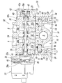
- the main difference between the manifold assembly 1B according to the second embodiment and the manifold assembly 1A according to the first embodiment is that instead of mounting the brackets 19 and 19 on the manifold block 2, This is because a leaf spring-like elastic member 60 having spring elasticity is attached to the drawing groove 14.
- the same reference numerals as those of the manifold assembly 1A of the first embodiment are given to the same main components of both, and descriptions of those components and the effects based on the components are omitted to avoid redundant description. .
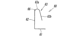
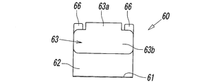
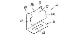
- the elastic member 60 includes a base portion 61 having a substantially flat plate shape, a standing portion 62 that rises in a substantially orthogonal direction from a side edge of the base portion 61, and a tip of the standing portion 62.
- the spring part 63 is inverted from the base part toward the base part 61 and curved in a substantially arc shape.
- the elastic member 60 is integrally formed by a thin plate made of a metal material such as stainless steel.
- the base 61 is provided with a substantially rectangular hole 65 penetrating in the thickness direction.
- This hole 65 is used, for example, when removing the elastic member 60 attached to the manifold block 2.
- the elastic member 60 in a locked state with respect to the mounting grooves 8a and 8b by hooking a tip of a tool or the like on the edge of the hole 65 and pulling it outward (bottom direction shown in FIG. 7).
- the standing portion 62 is formed in a substantially flat plate shape having the same width as the base portion 61, and is flush with the standing portion 62 in the rising direction of the standing portion 62 at both ends at the tip thereof.
- a pair of projecting pieces 66, 66 extending in the form of are respectively formed.
- the spring part 63 is formed by bending and bending an intermediate part sandwiched between the pair of protruding pieces 66, 66 at the tip of the standing part 62 toward the base part 61 side. It consists of a curved portion 63a located between the protruding pieces 66, 66 and a flat straight portion 63b formed wider than the curved portion 63a.
- the curved portion 63a has a convex shape having a top on the opposite side to the base 61, and the straight portion 63b is inclined in a direction away from the standing portion 62 toward the tip side.
- the spring portion 63 can be bent in a direction in which the spring portion 63 contacts and separates from the standing portion 62 with the curved portion 63a as a center.
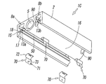
- mounting holes 90 penetrating the valve mounting surface 2A and the bottom surface are formed in the vicinity of both end surfaces in the longitudinal direction of the manifold block 2 (see FIG. 8).
- the mounting hole 90 is for inserting a mounting member such as a screw and fixing the manifold block 2 at a predetermined installation location.
- the mounting hole 90 includes the mounting grooves 8a, Along each line 8b, two (a total of four) are provided at positions separated by a certain distance.
- the longitudinal length of the silencer member 50 in the second embodiment is formed to be shorter than the longitudinal length of the manifold block 2, specifically, the two mounting holes 90 in the longitudinal direction of the manifold block 2. , 90 is formed shorter than the separation distance.
- the silencer member 50 is disposed between the two mounting holes 90, 90 in the first and second mounting grooves 8a, 8b, whereby the silencer member 50 is connected to the individual exhaust passages 9a, 9b.
- the first and second mounting grooves 8a and 8b are located at all the joining points.
- the silencer member 50 is accommodated in the first and second mounting grooves 8 a and 8 b, and the elastic member 60 is disposed on the bottom side of the manifold block 2.
- the elastic member 60 is in a posture in which the spring portion 63 faces upward (upper side in FIG. 7), and the linear portion 63b of the spring portion 63 and the arcuate wall portion 17 of the manifold block 2 are opposed to each other.
- the elastic member 60 is pushed toward the exhaust ports 13a and 13b in the mounting grooves 8a and 8b through the space between the arcuate wall portion 17 and the central bottom portion 16, that is, the lightening groove 14.
- the straight portion 63b of the spring portion 63 abuts on the arc-shaped wall portion 17 (specifically, the upper wall surface sandwiching the notch 18 in FIG. 7), and the spring portion 63 faces the standing portion 62 side.
- the elastic member 60 is elastically press-fitted between the arc-shaped wall portion 17 of the manifold block 2 and the protruding wall portion 12 and the central wall portion 16.
- the linear portion 63b of the spring portion 63 is pressed against the arc-shaped wall portion 17 by the elastic force of the spring portion 63 which is bent and elastically deformed, and the upright portion 62 is a protruding wall portion. 12 and the central wall portion 16 in a state of being in pressure contact with each other, it is mounted in the above-described hollowing groove 14.
- a part of the elastic member 60 (curved portion 63a at the tip) is disposed in the mounting groove through the exhaust port, whereby the elastic member 60 comes into contact with the silencer member 50 and the silencer member 50 Is pressed against the bottom wall portion 10 of the mounting grooves 8a and 8b.
- the pair of projecting pieces 66, 66 in the elastic member 60 are stuck or strongly abutted on the silencer member 50 made of a fiber assembly, and thereby the silencer member 50 is restrained from moving. It is held in the mounting grooves 8a and 8b.
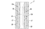
- FIG. 7 and 8 show an example in which two elastic members 60, 60 are attached to the first attachment groove 8a and the second attachment groove 8b, respectively.
- the number of elastic members 60 attached to each of the attachment grooves 8a and 8b may be one, or may be three or more.
- different numbers of elastic members 60 may be attached to the first attachment groove 8a and the second attachment groove 8b, respectively.
- it can set suitably also in the space
- FIG. 12 shows a modification of the elastic member.
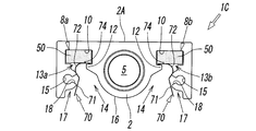
- the elastic member 70 according to this modification is also integrally formed by a thin plate made of a metal material, and includes a base portion 71 having a substantially flat plate shape and a substantially arcuate spring portion 72 continuous with the base portion 71. Has been.
- the base 71 has a substantially circular hole 73 penetrating in the thickness direction. This hole 73 is for facilitating the removal of the elastic member 70 attached to the manifold block 2 in the same manner as the hole 65 formed in the elastic member 60 in the second embodiment.
- the spring portion 72 includes a flat first plane portion 72a bent from the edge of the base portion 71 at an obtuse angle with respect to the base portion 71, and the first plane portion 72a. From a curved portion 72b that is curved in a direction substantially orthogonal to the base 71, a flat second plane portion 72c that is smoothly connected to a leading edge of the curved portion 72b, and an edge of the second plane portion 72c The second flat surface portion 72c is bent at an obtuse angle and is composed of a distal end portion 72d inclined toward the base 71 side.
- the second plane portion 72c and the tip end portion 72d are bent in a direction in which the second plane portion 72c and the tip end portion 72d are in contact with and separated from the first plane portion 72a with the curved portion 72b in the spring portion 72 as the center. It can be done.
- the elastic member 70 is provided with a substantially L-shaped projecting piece 74 that rises from the plate surface of the second flat portion 72c outward at a substantially right angle on the second flat portion 72c.
- the protruding piece 74 is formed by cutting and raising the plate surface of the second flat portion 72c, and is inserted into the silencer member 50 in the same manner as the protruding piece 66 of the elastic member 60 according to the second embodiment.
- the silencer member 50 can be prevented from moving in the mounting grooves 8a and 8b by hitting it strongly.
- the silencer member 50 is accommodated in the first and second mounting grooves 8a and 8b, and the elastic member 70 is disposed on the bottom surface side of the manifold block 2 as shown in FIG. At this time, the elastic member 70 is in a posture in which the spring portion 72 faces upward, and the convex side of the curved spring portion 72 and the arcuate wall portion 17 of the manifold block 2 are opposed to each other.
- the distal end portion 72d of the spring portion 72 is inserted between the bottom surface of the silencer member 50 and the protruding wall portion 12 of the mounting grooves 8a and 8b through the exhaust ports 13a and 13b. Then, the mounting grooves 8a and 8b are brought into contact with the inner corners where the protruding wall 12 and the side wall 11 intersect (see FIG. 14). In this state, the spring portion 72 is further moved in the depth direction of the thinned portion 14, that is, the exhaust port 13a. It press-fits to the side 13b, and abuts against the arc-shaped wall portion 17 (specifically, the upper wall surface sandwiching the notch 18 in FIGS. 13 and 14) in a state where the spring portion 72 is bent.
- the elastic member 70 has an arc shape of the corner portion where the protruding wall portion 12 and the side wall portion 11 intersect with the cutout portion 14. It is elastically held between the walls 17.
- the second straight portion 72c of the elastic member 70 is pressed against the bottom surface of the silencer member 50 by the elastic force of the spring portion 72, and the silencer member 50 is attached to the bottom walls of the mounting grooves 8a and 8b. It is pressed against the part 10.
- the protruding piece 74 of the elastic member 70 is stuck into or strongly hits the silencer member 50, and the movement of the silencer member 50 in the mounting grooves 8a and 8b is more reliably prevented.
- the solenoid valve manifold assembly 1C to which the elastic member 70 according to the modification is mounted, is configured (see FIGS. 13 and 14).
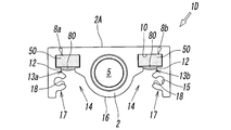
- FIGS. 16 and 17 show a solenoid valve manifold assembly 1D according to a third embodiment of the present invention.
- the silencer member 50 is held in the mounting grooves 8a and 8b by using an adhesive. Specifically, first, as described in the previous embodiment, the silencer member 50 is inserted into the first and second mounting grooves 8a and 8b, respectively. In this state, the adhesive 80 is introduced between the inner walls of the mounting grooves 8a and 8b and the outer peripheral surface of the silencer member 50 from the exhaust ports 13a and 13b side of the mounting grooves 8a and 8b.
- the silencer member 50 is fixed to the groove walls of the mounting grooves 8a and 8b with the hardened adhesive 80 (in the example of FIG. 16, the bottom surface side of the silencer member 50 and the protruding walls of the mounting grooves 8a and 8a).
- the wall surface of the portion 12) and the silencer member 50 can be held in the mounting grooves 8a and 8b in a state in which the movement is restricted.
- an adhesive bridge extending in the entire width direction of the exhaust ports 13 a and 13 b is formed so as to connect the protruding wall portions 12 and 12 facing each other.
- the silencer member 50 can be securely held in the mounting grooves 8a and 8b.
- the type of adhesive is not particularly limited as long as the silencer member 50 can be held in the mounting grooves 8a and 8b.
- the said silencer member 50 is adhere
- the single pilot type electromagnetic valve 30 including the single pilot valve 31 is mounted on the valve mounting surface 2A of the manifold block.
- a double pilot type solenoid valve provided may be mounted.
- the mounting grooves 8a and 8b have a substantially rectangular cross section, but this is not always necessary.
- the mounting grooves 8a and 8b may have other shapes such as a circle or an ellipse. good.
- the silencer member 50 may be formed in accordance with the cross-sectional shape.
- the entire silencer member 50 is integrally formed of a silencer.
- the silencer member 50 is formed such that the silencer is disposed at least at the junction between the individual exhaust passages 9a and 9b and the mounting grooves 8a and 8b.
- it may be formed by a combination of a sound deadening material and another material.
- the protruding wall portions 12 of the mounting grooves 8a and 8b forming the exhaust ports 13a and 13b are formed over the entire mounting groove.
- the silencer member 50 can be held in the grooves. It can also be provided partially along the axial direction.
- Manifold assembly 1A, 1B, 1C, 1D Manifold assembly 2 Manifold block 2A Valve mounting surface 3 Fixed area 5
- Collective air supply path 6 Individual air supply path 8a, 8b Mounting groove 9a, 9b Individual exhaust path 30
- Solenoid valve 50 Silencer member 60, 70 Elastic member 80 Adhesive
Landscapes
- Engineering & Computer Science (AREA)
- General Engineering & Computer Science (AREA)
- Mechanical Engineering (AREA)
- Physics & Mathematics (AREA)
- Fluid Mechanics (AREA)
- Electromagnetism (AREA)
- Chemical & Material Sciences (AREA)
- Analytical Chemistry (AREA)
- Valve Housings (AREA)
- Details Of Valves (AREA)
- Exhaust Silencers (AREA)
Abstract
Description
なお、上記技術的課題は、上記電磁弁用マニホールド組立体における上記弁搭載面の固定領域に、複数の電磁弁を搭載して成る電磁弁集合体によっても解決することができる。
図1又は図3に示すように、マニホールド組立体1Aを構成するマニホールドブロック2は、鋳造等により一体成型された長い略直方体のブロック体から成っていて、平坦面であるその上面が、上記電磁弁30を搭載するための弁搭載面2Aを形成している。図3において破線(仮想線)で示すように、この弁搭載面2Aには、上記電磁弁30を個々に固定するための複数の固定領域3が設けられており、これら固定領域3は、上記マニホールドブロック2の長手方向に沿って並設されている。
なお、本実施形態においては、弁搭載面2A上に電磁弁30を搭載したとき、第1個別排気路9aは、電磁弁30に開設された上記第1排出通孔37aに接続され、また、第2個別排気路9bは、電磁弁30の第2排出通孔37bに接続される(図6参照)。
先ず、サイレンサ部材50を、上記第1及び第2取付溝8a,8b内に収容すると共に、上記弾性部材60をマニホールドブロック2の底面側に配置する。このとき、上記弾性部材60を、ばね部63が上向き(図7の上側)となる姿勢とし、当該ばね部63の直線部分63bと、マニホールドブロック2の弧状壁部17とを対向させる。そして、上記弾性部材60を、該弧状壁部17と上記中央底部16との間の空間、すなわち肉抜き溝14を通じて、取付溝8a,8bにおける排気口13a,13bに向けて押し込んでいく。
先ず、サイレンサ部材50を上記第1及び第2取付溝8a,8b内に収容すると共に、図15に示すように、上記弾性部材70をマニホールドブロック2の底面側に配置する。このとき、弾性部材70を、上記ばね部72が上向きとなる姿勢とし、湾曲形成されたばね部72の凸側とマニホールドブロック2の弧状壁部17とを対向させる。
2 マニホールドブロック
2A 弁搭載面
3 固定領域
5 一括給気路
6 個別給気路
8a,8b 取付溝
9a,9b 個別排気路
30 電磁弁
50 サイレンサ部材
60,70 弾性部材
80 接着剤
Claims (14)
- 複数の電磁弁を並べて搭載するための電磁弁用マニホールド組立体であって、
上記マニホールド組立体は、上記電磁弁をそれぞれ固定するための複数の固定領域が並設されて成る弁搭載面と、該弁搭載面の各固定領域にそれぞれ開口していて、上記各電磁弁に対して圧縮空気を供給するための給気流路とを有するマニホールドブロック、及び、上記各電磁弁から排出される排気の排気音を抑制するためのサイレンサ部材を含んでおり、
上記マニホールドブロックは、上記サイレンサ部材を装着するための取付溝と、該取付溝から分岐されて上記弁搭載面の各固定領域にそれぞれ開口する複数の個別排気路とをさらに含んでいて、該取付溝における軸に沿った開口が、排気口として上記マニホールドブロックの外周面に開設され、該取付溝内に上記サイレンサ部材が保持されており、
上記各個別排気路が、上記サイレンサ部材を通じて上記排気口にそれぞれ連通されていることを特徴とするもの。 - 請求項1に記載の電磁弁用マニホールド組立体において、
上記取付溝が、上記弁搭載面における固定領域の並設方向に沿って形成されると共に、上記マニホールドブロックの両端面間を貫通していることを特徴とするもの。 - 請求項2に記載の電磁弁用マニホールド組立体において、
上記マニホールドブロックの両端面にはブラケットが着脱可能に固定されており、上記マニホールドブロックの両端面に開口する上記取付溝の各端部開口が、上記ブラケットによってそれぞれ閉塞されていることを特徴とするもの。 - 請求項2に記載の電磁弁用マニホールド組立体において、
上記マニホールドブロックの底面に、上記取付溝に沿って肉抜き溝が延設されており、該肉抜き溝の溝壁に上記排気口が開設されていることを特徴とするもの。 - 請求項4に記載の電磁弁用マニホールド組立体において、
上記肉抜き溝には、ばね弾性を有する弾性部材が弾性変形した状態でその弾発力によって装着されていると共に、この弾性部材が、上記排気口を通じて取付溝内のサイレンサ部材に当接することにより、該サイレンサ部材が上記取付溝内に保持されていることを特徴とするもの。 - 請求項5に記載の電磁弁用マニホールド組立体において、
上記弾性部材が、上記弾性変形による弾発力で上記サイレンサ部材に対して圧接されていることを特徴とするもの。 - 請求項2に記載の電磁弁用マニホールド組立体において、
上記サイレンサ部材が、上記取付溝内に接着剤で固定されることにより、該取付溝内に保持されていることを特徴とするもの。 - 請求項2に記載の電磁弁用マニホールド組立体において、
上記給気流路が、上記複数の電磁弁に供給する圧縮空気を一括して流すための一括給気路と、該一括給気路から分岐されて上記弁搭載面にそれぞれ開口する複数の個別給気路とにより構成され、上記一括給気路が、上記取付溝と平行を成してマニホールドブロックの両端面間を貫通していることを特徴とするもの。 - 請求項8に記載の電磁弁用マニホールド組立体において、
上記取付溝が、上記一括給気路を挟んだ両側にそれぞれ設けられていることを特徴とするもの。 - 請求項1に記載の電磁弁用マニホールド組立体において、
上記サイレンサ部材は消音材を含んでいて、該消音材が、上記取付溝における少なくとも上記個別排気路との合流部分に配置されていることを特徴とするもの。 - 請求項2に記載の電磁弁用マニホールド組立体において、
上記サイレンサ部材は消音材を含んでいて、該消音材が、上記取付溝における少なくとも上記個別排気路との合流部分に配置されていることを特徴とするもの。 - 請求項10に記載の電磁弁用マニホールド組立体において、
上記サイレンサ部材が、上記消音材によって、上記取付溝と実質的に同じ横断面を有するスティック状に一体成形されたものであり、該取付溝と実質的に同じ軸方向長さを有していることを特徴とするもの。 - 請求項11に記載の電磁弁用マニホールド組立体において、
上記サイレンサ部材が、上記消音材によって、上記取付溝と実質的に同じ横断面を有するスティック状に一体成形されたものであり、該取付溝と実質的に同じ軸方向長さを有していることを特徴とするもの。 - 請求項1に記載の電磁弁用マニホールド組立体における上記弁搭載面の固定領域に、複数の電磁弁を搭載して成る電磁弁集合体。
Priority Applications (8)
| Application Number | Priority Date | Filing Date | Title |
|---|---|---|---|
| KR1020187014969A KR102540684B1 (ko) | 2015-12-14 | 2016-08-26 | 전자 밸브용 매니폴드 조립체 및 그것을 사용한 전자 밸브 집합체 |
| US15/779,690 US11092255B2 (en) | 2015-12-14 | 2016-08-26 | Manifold assembly for electromagnetic valve and electromagnetic valve cluster using same |
| RU2018125898A RU2716954C2 (ru) | 2015-12-14 | 2016-08-26 | Узел коллектора для электромагнитного клапана и блок электромагнитных клапанов, использующих такой узел |
| MX2018007108A MX2018007108A (es) | 2015-12-14 | 2016-08-26 | Ensamblaje de colector para valvula electromagnetica y agrupamiento de valvulas electromagneticas utilizando el mismo. |
| BR112018010910-0A BR112018010910A2 (ja) | 2015-12-14 | 2016-08-26 | The manifold assembly object for electromagnetic valves, and the electromagnetic valve aggregate using it |
| CN201680073254.3A CN108368947B (zh) | 2015-12-14 | 2016-08-26 | 电磁阀用歧管组装体及使用它的电磁阀集合体 |
| JP2017556355A JP6743347B2 (ja) | 2015-12-14 | 2016-08-26 | 電磁弁用マニホールド組立体及びそれを用いた電磁弁集合体 |
| DE112016005706.7T DE112016005706B4 (de) | 2015-12-14 | 2016-08-26 | Verteileranordnung für Elektromagnetventile und diese verwendendes Elektromagnetventilcluster |
Applications Claiming Priority (2)
| Application Number | Priority Date | Filing Date | Title |
|---|---|---|---|
| JP2015-243265 | 2015-12-14 | ||
| JP2015243265 | 2015-12-14 |
Publications (1)
| Publication Number | Publication Date |
|---|---|
| WO2017104179A1 true WO2017104179A1 (ja) | 2017-06-22 |
Family
ID=59056316
Family Applications (1)
| Application Number | Title | Priority Date | Filing Date |
|---|---|---|---|
| PCT/JP2016/074927 Ceased WO2017104179A1 (ja) | 2015-12-14 | 2016-08-26 | 電磁弁用マニホールド組立体及びそれを用いた電磁弁集合体 |
Country Status (10)
| Country | Link |
|---|---|
| US (1) | US11092255B2 (ja) |
| JP (1) | JP6743347B2 (ja) |
| KR (1) | KR102540684B1 (ja) |
| CN (1) | CN108368947B (ja) |
| BR (1) | BR112018010910A2 (ja) |
| DE (1) | DE112016005706B4 (ja) |
| MX (1) | MX2018007108A (ja) |
| RU (1) | RU2716954C2 (ja) |
| TW (1) | TWI721007B (ja) |
| WO (1) | WO2017104179A1 (ja) |
Cited By (7)
| Publication number | Priority date | Publication date | Assignee | Title |
|---|---|---|---|---|
| WO2018150932A1 (ja) * | 2017-02-16 | 2018-08-23 | Smc株式会社 | 電磁弁用マニホールドベース及びマニホールド型電磁弁 |
| CN109296781A (zh) * | 2018-10-30 | 2019-02-01 | 安沃驰气动设备(常州)有限公司 | 一种新型吹瓶组合阀 |
| RU2721564C1 (ru) * | 2019-09-13 | 2020-05-20 | Общество с ограниченной ответственностью Финансово-промышленная компания "Космос-Нефть-Газ" | Модуль обвязки скважин |
| RU2721573C1 (ru) * | 2019-09-13 | 2020-05-20 | Общество с ограниченной ответственностью Финансово-промышленная компания "Космос-Нефть-Газ" | Модуль обвязки скважины |
| RU2726813C1 (ru) * | 2019-09-13 | 2020-07-15 | Общество с ограниченной ответственностью Финансово-промышленная компания "Космос-Нефть-Газ" | Шкаф управления фонтанной арматурой |
| RU2726815C1 (ru) * | 2019-09-13 | 2020-07-15 | Общество с ограниченной ответственностью Финансово-промышленная компания "Космос-Нефть-Газ" | Шкаф управления фонтанными арматурами |
| DE102020134767A1 (de) | 2020-12-22 | 2022-06-23 | Bürkert Werke GmbH & Co. KG | Ventilbauteil und Ventileinheit |
Families Citing this family (7)
| Publication number | Priority date | Publication date | Assignee | Title |
|---|---|---|---|---|
| US10613553B2 (en) * | 2013-07-09 | 2020-04-07 | Deka Products Limited Partnership | Modular valve apparatus and system |
| CN108895057A (zh) * | 2018-08-20 | 2018-11-27 | 佛山市赛普飞特机械有限公司 | 一种集成气动装置 |
| JP1720711S (ja) * | 2020-07-29 | 2022-07-26 | 電磁弁 | |
| JP1711457S (ja) * | 2020-09-07 | 2022-04-01 | 電磁弁 | |
| JP1711581S (ja) * | 2020-09-07 | 2022-04-01 | 電磁弁 | |
| JP1711456S (ja) * | 2020-09-07 | 2022-04-01 | 電磁弁 | |
| JP1711580S (ja) * | 2020-09-07 | 2022-04-01 | 電磁弁 |
Citations (2)
| Publication number | Priority date | Publication date | Assignee | Title |
|---|---|---|---|---|
| JPH0227074U (ja) * | 1988-08-09 | 1990-02-22 | ||
| JPH04290602A (ja) * | 1991-03-18 | 1992-10-15 | Smc Corp | 流体制御機構付マニホールド |
Family Cites Families (12)
| Publication number | Priority date | Publication date | Assignee | Title |
|---|---|---|---|---|
| DE4305608A1 (de) * | 1993-02-24 | 1994-08-25 | Bosch Gmbh Robert | Ventilblock |
| JP3486238B2 (ja) * | 1994-09-21 | 2004-01-13 | Smc株式会社 | 切換弁 |
| RU2211382C2 (ru) * | 2001-09-17 | 2003-08-27 | Открытое акционерное общество "Павловский машиностроительный завод ВОСХОД" | Пневмораспределитель клапанного типа |
| JP4482758B2 (ja) | 2005-02-16 | 2010-06-16 | Smc株式会社 | マニホールドベース組立体 |
| JP4919002B2 (ja) | 2005-06-20 | 2012-04-18 | Smc株式会社 | マニホールド形電磁弁集合体 |
| CN100497963C (zh) * | 2005-06-20 | 2009-06-10 | Smc株式会社 | 汇流型电磁阀集合体 |
| CN2921493Y (zh) * | 2006-06-15 | 2007-07-11 | 张坤林 | 降低噪声的电磁气阀 |
| JP2009257554A (ja) | 2008-04-21 | 2009-11-05 | Smc Corp | 電磁弁用マニホールド |
| CN202528966U (zh) * | 2012-04-22 | 2012-11-14 | 焦同 | 一种防抱死刹车电磁阀 |
| CN103032606B (zh) * | 2012-12-28 | 2014-06-11 | 无锡市拓发自控设备有限公司 | 具有三级安全功能的双联阀 |
| CN203230964U (zh) | 2013-05-10 | 2013-10-09 | 无锡鑫常钢管有限责任公司 | 一种高温高压高腐蚀设备用不锈钢管 |
| CN105065728A (zh) * | 2015-07-21 | 2015-11-18 | 奉化市盛强晨亿机械有限公司 | 一种低功耗电磁阀 |
-
2016
- 2016-08-26 CN CN201680073254.3A patent/CN108368947B/zh active Active
- 2016-08-26 JP JP2017556355A patent/JP6743347B2/ja active Active
- 2016-08-26 US US15/779,690 patent/US11092255B2/en active Active
- 2016-08-26 WO PCT/JP2016/074927 patent/WO2017104179A1/ja not_active Ceased
- 2016-08-26 BR BR112018010910-0A patent/BR112018010910A2/ja active Search and Examination
- 2016-08-26 RU RU2018125898A patent/RU2716954C2/ru active
- 2016-08-26 MX MX2018007108A patent/MX2018007108A/es unknown
- 2016-08-26 DE DE112016005706.7T patent/DE112016005706B4/de active Active
- 2016-08-26 KR KR1020187014969A patent/KR102540684B1/ko active Active
- 2016-08-30 TW TW105127895A patent/TWI721007B/zh active
Patent Citations (2)
| Publication number | Priority date | Publication date | Assignee | Title |
|---|---|---|---|---|
| JPH0227074U (ja) * | 1988-08-09 | 1990-02-22 | ||
| JPH04290602A (ja) * | 1991-03-18 | 1992-10-15 | Smc Corp | 流体制御機構付マニホールド |
Cited By (9)
| Publication number | Priority date | Publication date | Assignee | Title |
|---|---|---|---|---|
| WO2018150932A1 (ja) * | 2017-02-16 | 2018-08-23 | Smc株式会社 | 電磁弁用マニホールドベース及びマニホールド型電磁弁 |
| US10900581B2 (en) | 2017-02-16 | 2021-01-26 | Smc Corporation | Manifold base for electromagnetic valve and manifold-type electromagnetic valve |
| CN109296781A (zh) * | 2018-10-30 | 2019-02-01 | 安沃驰气动设备(常州)有限公司 | 一种新型吹瓶组合阀 |
| CN109296781B (zh) * | 2018-10-30 | 2023-09-22 | 世格流体控制(上海)有限公司 | 一种新型吹瓶组合阀 |
| RU2721564C1 (ru) * | 2019-09-13 | 2020-05-20 | Общество с ограниченной ответственностью Финансово-промышленная компания "Космос-Нефть-Газ" | Модуль обвязки скважин |
| RU2721573C1 (ru) * | 2019-09-13 | 2020-05-20 | Общество с ограниченной ответственностью Финансово-промышленная компания "Космос-Нефть-Газ" | Модуль обвязки скважины |
| RU2726813C1 (ru) * | 2019-09-13 | 2020-07-15 | Общество с ограниченной ответственностью Финансово-промышленная компания "Космос-Нефть-Газ" | Шкаф управления фонтанной арматурой |
| RU2726815C1 (ru) * | 2019-09-13 | 2020-07-15 | Общество с ограниченной ответственностью Финансово-промышленная компания "Космос-Нефть-Газ" | Шкаф управления фонтанными арматурами |
| DE102020134767A1 (de) | 2020-12-22 | 2022-06-23 | Bürkert Werke GmbH & Co. KG | Ventilbauteil und Ventileinheit |
Also Published As
| Publication number | Publication date |
|---|---|
| US20200309279A1 (en) | 2020-10-01 |
| CN108368947B (zh) | 2022-10-28 |
| RU2716954C2 (ru) | 2020-03-17 |
| RU2018125898A (ru) | 2020-01-16 |
| KR20180092944A (ko) | 2018-08-20 |
| RU2018125898A3 (ja) | 2020-01-22 |
| KR102540684B1 (ko) | 2023-06-08 |
| TW201723366A (zh) | 2017-07-01 |
| JPWO2017104179A1 (ja) | 2018-10-04 |
| DE112016005706B4 (de) | 2025-01-16 |
| TWI721007B (zh) | 2021-03-11 |
| US11092255B2 (en) | 2021-08-17 |
| JP6743347B2 (ja) | 2020-08-19 |
| BR112018010910A2 (ja) | 2018-11-21 |
| MX2018007108A (es) | 2018-09-07 |
| DE112016005706T5 (de) | 2018-09-06 |
| CN108368947A (zh) | 2018-08-03 |
Similar Documents
| Publication | Publication Date | Title |
|---|---|---|
| WO2017104179A1 (ja) | 電磁弁用マニホールド組立体及びそれを用いた電磁弁集合体 | |
| CN110291318B (zh) | 电磁阀用歧管基座及歧管型电磁阀 | |
| JP5560276B2 (ja) | 流体制御器 | |
| JP2012031930A (ja) | 多連バルブ搭載用一体型マニホールドバルブ | |
| KR102540683B1 (ko) | 전자밸브 및 매니폴드형 전자밸브 집합체 | |
| KR101321758B1 (ko) | 다연식 전자 밸브 | |
| WO2017061400A1 (ja) | スプール弁 | |
| KR20080084632A (ko) | 파일럿형 3포트 밸브 | |
| JP5612580B2 (ja) | 滑り弁 | |
| JP2015187470A (ja) | マニホールド電磁弁 | |
| JP6134285B2 (ja) | マニホールド電磁弁 | |
| JP4778077B2 (ja) | マニホールド電磁弁 | |
| KR0137003Y1 (ko) | 집합형 변환밸브 | |
| MX2021001119A (es) | Estructura de sellado para valvula de conmutacion de tipo carrete y dicha valvula de conmutacion de tipo carrete. | |
| JP3109097U (ja) | 切換え弁装置 | |
| JP2005106069A (ja) | 多段エゼクタ装置 |
Legal Events
| Date | Code | Title | Description |
|---|---|---|---|
| 121 | Ep: the epo has been informed by wipo that ep was designated in this application |
Ref document number: 16875166 Country of ref document: EP Kind code of ref document: A1 |
|
| ENP | Entry into the national phase |
Ref document number: 20187014969 Country of ref document: KR Kind code of ref document: A |
|
| REG | Reference to national code |
Ref country code: BR Ref legal event code: B01A Ref document number: 112018010910 Country of ref document: BR |
|
| ENP | Entry into the national phase |
Ref document number: 2017556355 Country of ref document: JP Kind code of ref document: A |
|
| WWE | Wipo information: entry into national phase |
Ref document number: MX/A/2018/007108 Country of ref document: MX |
|
| WWE | Wipo information: entry into national phase |
Ref document number: 112016005706 Country of ref document: DE |
|
| WWE | Wipo information: entry into national phase |
Ref document number: 2018125898 Country of ref document: RU |
|
| ENP | Entry into the national phase |
Ref document number: 112018010910 Country of ref document: BR Kind code of ref document: A2 Effective date: 20180529 |
|
| 122 | Ep: pct application non-entry in european phase |
Ref document number: 16875166 Country of ref document: EP Kind code of ref document: A1 |