WO2017104176A1 - 電池パック及び電池パックの製造方法 - Google Patents
電池パック及び電池パックの製造方法 Download PDFInfo
- Publication number
- WO2017104176A1 WO2017104176A1 PCT/JP2016/074524 JP2016074524W WO2017104176A1 WO 2017104176 A1 WO2017104176 A1 WO 2017104176A1 JP 2016074524 W JP2016074524 W JP 2016074524W WO 2017104176 A1 WO2017104176 A1 WO 2017104176A1
- Authority
- WO
- WIPO (PCT)
- Prior art keywords
- counterweight
- wall portion
- hole
- battery pack
- bolt
- Prior art date
- Legal status (The legal status is an assumption and is not a legal conclusion. Google has not performed a legal analysis and makes no representation as to the accuracy of the status listed.)
- Ceased
Links
Images





Classifications
-
- H—ELECTRICITY
- H01—ELECTRIC ELEMENTS
- H01M—PROCESSES OR MEANS, e.g. BATTERIES, FOR THE DIRECT CONVERSION OF CHEMICAL ENERGY INTO ELECTRICAL ENERGY
- H01M50/00—Constructional details or processes of manufacture of the non-active parts of electrochemical cells other than fuel cells, e.g. hybrid cells
- H01M50/20—Mountings; Secondary casings or frames; Racks, modules or packs; Suspension devices; Shock absorbers; Transport or carrying devices; Holders
- H01M50/204—Racks, modules or packs for multiple batteries or multiple cells
-
- H—ELECTRICITY
- H01—ELECTRIC ELEMENTS
- H01M—PROCESSES OR MEANS, e.g. BATTERIES, FOR THE DIRECT CONVERSION OF CHEMICAL ENERGY INTO ELECTRICAL ENERGY
- H01M50/00—Constructional details or processes of manufacture of the non-active parts of electrochemical cells other than fuel cells, e.g. hybrid cells
- H01M50/20—Mountings; Secondary casings or frames; Racks, modules or packs; Suspension devices; Shock absorbers; Transport or carrying devices; Holders
- H01M50/218—Mountings; Secondary casings or frames; Racks, modules or packs; Suspension devices; Shock absorbers; Transport or carrying devices; Holders characterised by the material
- H01M50/22—Mountings; Secondary casings or frames; Racks, modules or packs; Suspension devices; Shock absorbers; Transport or carrying devices; Holders characterised by the material of the casings or racks
- H01M50/222—Inorganic material
- H01M50/224—Metals
-
- H—ELECTRICITY
- H01—ELECTRIC ELEMENTS
- H01M—PROCESSES OR MEANS, e.g. BATTERIES, FOR THE DIRECT CONVERSION OF CHEMICAL ENERGY INTO ELECTRICAL ENERGY
- H01M50/00—Constructional details or processes of manufacture of the non-active parts of electrochemical cells other than fuel cells, e.g. hybrid cells
- H01M50/20—Mountings; Secondary casings or frames; Racks, modules or packs; Suspension devices; Shock absorbers; Transport or carrying devices; Holders
- H01M50/271—Lids or covers for the racks or secondary casings
-
- Y—GENERAL TAGGING OF NEW TECHNOLOGICAL DEVELOPMENTS; GENERAL TAGGING OF CROSS-SECTIONAL TECHNOLOGIES SPANNING OVER SEVERAL SECTIONS OF THE IPC; TECHNICAL SUBJECTS COVERED BY FORMER USPC CROSS-REFERENCE ART COLLECTIONS [XRACs] AND DIGESTS
- Y02—TECHNOLOGIES OR APPLICATIONS FOR MITIGATION OR ADAPTATION AGAINST CLIMATE CHANGE
- Y02E—REDUCTION OF GREENHOUSE GAS [GHG] EMISSIONS, RELATED TO ENERGY GENERATION, TRANSMISSION OR DISTRIBUTION
- Y02E60/00—Enabling technologies; Technologies with a potential or indirect contribution to GHG emissions mitigation
- Y02E60/10—Energy storage using batteries
Definitions
- the present invention relates to a battery pack and a battery pack manufacturing method.
- Patent Document 1 discloses a battery pack that includes a battery module having battery cells and a housing that houses the battery module.
- the casing has a predetermined thickness and functions as a counterweight.
- the battery pack casing as described above is often formed by joining a plurality of members by welding.
- the thicker the member the longer the welding time.
- a difference is easily generated in the quality of the joint. Therefore, it is conceivable that the casing is formed of a thin plate, and the counterweight and the battery module are fastened with a fastening member such as a bolt with the thin plate interposed therebetween.
- the counterweight and the battery module may move in a direction intersecting the axial direction of the fastening member due to an impact. As a result, the fastening of the bolt may be loosened.
- the present invention provides a battery pack and a method for manufacturing the battery pack that can facilitate the manufacture and improve the impact resistance.
- the battery pack includes a battery module, a housing, a counterweight, and a fastening member.
- the housing has a wall portion provided with a through hole and accommodates the battery module.
- the counterweight is welded to the wall.
- the fastening member fastens the battery module and the counterweight, which are arranged to face each other through the wall portion, through the through hole.
- the housing is separate from the counterweight. For this reason, a housing
- casing can be formed with a thin plate. Therefore, welding work when forming the housing is facilitated. As a result, the manufacture of the battery pack can be facilitated.
- the counterweight is fastened to the battery module through a through hole by a fastening member.
- the counterweight is welded to the wall portion of the housing. For this reason, the position of the counterweight is fixed with respect to the wall portion. Thereby, the counterweight does not move in the direction intersecting the axial direction of the fastening member even by an impact. Therefore, the fastening of the fastening member is difficult to loosen. As a result, the impact resistance of the battery pack can be improved.
- the counterweight may have a facing surface that faces the wall.
- the wall portion may have a covering region covered by the facing surface.
- Each of the facing surface and the covering region may not be painted.
- the counterweight and the wall portion can be applied simultaneously in an integrated state. Therefore, the painting work can be facilitated as compared with the case where the counterweight and the wall portion are painted separately.
- a battery pack manufacturing method includes a step of fastening a counterweight to a wall portion of a housing, and welding the counterweight to the wall portion in a state where the counterweight is fastened to the wall portion.
- the battery module is disposed to face the counterweight through the wall, and the counterweight and the battery module are disposed through the through-hole provided in the wall. Fastening with a fastening member.
- the wall portion is strongly in close contact with the counterweight when fastened. For this reason, the wall portion is easily maintained in a shape along the counterweight. Thereby, it becomes possible to suppress the curvature of the wall part by welding.
- the battery pack manufacturing method may further include a step of painting the wall portion and the counterweight in a state where the counterweight is fastened to the wall portion and the counterweight is welded to the wall portion.
- the counterweight and the wall are applied simultaneously in an integrated state. For this reason, compared with the case where a counterweight and a wall part are painted separately, a painting operation can be facilitated.
- the counterweight may be fastened to the wall portion by a fastening member through the through hole.
- a fastening member through the through hole.
- manufacturing can be facilitated and impact resistance can be improved.
- FIG. 1 is a cross-sectional view illustrating a battery pack according to an embodiment.
- the battery pack 1 includes a battery module 10, a housing 20, a counterweight 31 to a counterweight 33, bolts B1 to B3, and welds W1 to W4. ing.
- the battery pack 1 is a device used as a battery for vehicles such as electric vehicles and forklifts.
- the battery module 10 has a plurality of battery cells (not shown), a pair of end plates 11, and a pair of brackets 12.
- the weight of the battery module 10 is 20 kg or more, for example.
- the battery cell is a storage battery such as a non-aqueous electrolyte secondary battery such as a lithium ion secondary battery, or an electric double layer capacitor.
- the plurality of battery cells are arranged in a predetermined direction (X direction) while being electrically connected to each other.
- the pair of end plates 11 are arranged on both sides in the X direction of the plurality of battery cells arranged in this way.
- the pair of end plates 11 fixes and integrates a plurality of battery cells.
- the bracket 12 is a member for fixing and attaching a plurality of battery cells to the housing 20.
- the bracket 12 is attached to the end plate 11 on both sides in the X direction of the plurality of battery cells.
- the bracket 12 is attached to the end plate 11 with a bolt (not shown), for example.
- the bracket 12 is provided with a plurality of through holes 12a. Bolts B2 and B3 are inserted in the Y direction through the plurality of through holes 12a. Thereby, the battery module 10 is fixed to the front wall portion 26 and the rear wall portion 28.
- the housing 20 is a box having a substantially rectangular parallelepiped shape as a whole.
- the housing 20 houses the battery module 10 in the housing space S inside the housing 20.
- the housing 20 houses, for example, four battery modules 10 in the housing space S.
- the length of the housing 20 in the X direction is, for example, 1000 mm.
- the length of the housing 20 in the Y direction orthogonal to the X direction is, for example, 400 mm.
- the length of the housing 20 in the Z direction orthogonal to the X direction and the Y direction is, for example, 600 mm.
- the housing 20 is formed of, for example, a thin plate having a thickness of 1 mm to 20 mm (preferably 1 mm to 10 mm).
- casing 20 is common steel materials, such as SS400 and SPHC, for example.
- the housing 20 has a main body 21 provided with an opening A and a lid body 22 that covers the opening A.
- the main body 21 includes a bottom wall portion 23, an upper wall portion 24, a pair of side wall portions 25, a front wall portion 26, and a flange portion 27.
- the main body 21 is integrated by the welded portion W1.
- the lid 22 includes a rear wall portion 28.
- the bottom wall portion 23 and the upper wall portion 24 have the same shape.
- the bottom wall portion 23 and the upper wall portion 24 are rectangular thin plates facing each other in the Z direction.
- the bottom wall portion 23 has an inner surface 23a.
- the inner surface 23a includes a covering region 23r.
- the covering region 23r is a region covered with a later-described facing surface 31a.
- the pair of side wall portions 25 have the same shape.
- the pair of side wall portions 25 are rectangular thin plates facing each other in the X direction.
- the front wall portion 26 and the rear wall portion 28 have the same shape.
- the front wall portion 26 and the rear wall portion 28 are rectangular thin plates facing each other in the Y direction.
- the front wall portion 26 has an inner surface 26a and an outer surface 26b.
- the outer surface 26b includes a covering region 26r.
- the covering region 26r is a region covered with a later-described facing surface 32a.
- the rear wall portion 28 has an inner surface 28a and an outer surface 28b.
- the outer surface 28b includes a covering region 28r.
- the covering region 28r is a region covered with a later-described facing surface 33a.
- the flange portion 27 is a rectangular frame-shaped thin plate.
- the flange portion 27 is erected toward the accommodation space S at the end of the bottom wall portion 23, the upper wall portion 24, and the pair of side wall portions 25 on the rear wall portion 28 side.
- An inner edge of the flange portion 27 defines an opening A.
- the width of the flange portion 27 (the width formed by the outer edge and the inner edge of the flange portion 27) is, for example, 30 mm.
- the flange portion 27 faces the rear wall portion 28 in the Y direction.
- the front wall portion 26 is provided with a plurality of through holes 26c.
- the through hole 26c is provided at a position overlapping the through hole 12a when viewed from the Y direction.
- the through hole 26 c is a hole for fixing the battery module 10 to the front wall portion 26.
- the bolt B2 is inserted through the through hole 26c in the Y direction.
- the rear wall 28 is provided with a plurality of through holes 28c and a plurality of through holes 28d.
- the through hole 28 d is a hole for fixing the lid body 22 to the main body 21.
- the through hole 28 d is provided in the peripheral edge portion of the rear wall portion 28.
- the peripheral edge portion of the rear wall portion 28 is a portion facing the flange portion 27 in the Y direction.
- the through hole 28 c is a hole for fixing the battery module 10 to the rear wall portion 28.
- the through hole 28 c is provided in the center portion surrounded by the peripheral edge portion of the rear wall portion 28.
- the through hole 28c is disposed at a position overlapping the through hole 12a when viewed from the Y direction.
- a bolt B3 is inserted through the through hole 28c in the Y direction.
- the flange portion 27 is provided with a plurality of screw holes 27a.
- the screw hole 27 a is a hole for fixing the lid body 22 to the main body 21.
- the screw hole 27a is provided at a position overlapping the through hole 28d when viewed from the Y direction.
- the screw hole 27 a may penetrate the flange portion 27.
- a bolt B1 is inserted through the through hole 28d and the screw hole 27a in the Y direction.
- the rear wall portion 28 is attached to the flange portion 27 with a bolt B1 through a seal member G.
- the rear wall portion 28 covers the opening A.
- the seal member G is, for example, a rectangular annular gasket.
- the seal member G is sandwiched between the rear wall portion 28 and the flange portion 27.
- the sealing member G keeps the accommodation space S airtight.
- the counterweight 31 has a substantially rectangular parallelepiped shape and is welded to the inner surface 23 a of the bottom wall portion 23. In other words, the counterweight 31 and the bottom wall portion 23 are integrated by the welded portion W2.
- the length of the counterweight 31 in the X direction is, for example, 950 mm.
- the length of the counterweight 31 in the Y direction is, for example, 350 mm.
- the length of the counterweight 31 in the Z direction is, for example, 50 mm.
- the weight of the counterweight 31 is 40 kg, for example.
- the counterweight 31 has a facing surface 31 a that faces the inner surface 23 a of the bottom wall portion 23.
- the counterweight 32 has a substantially rectangular parallelepiped shape.
- the counterweight 32 is welded to the outer surface 26 b of the front wall portion 26. In other words, the counterweight 32 and the front wall portion 26 are integrated by the welded portion W3.
- the length of the counterweight 32 in the X direction is, for example, 950 mm.
- the length of the counterweight 32 in the Y direction is, for example, 50 mm.
- the length of the counterweight 32 in the Z direction is, for example, 530 mm.
- the weight of the counterweight 32 is 40 kg, for example.
- the counterweight 32 has a facing surface 32 a that faces the outer surface 26 b of the front wall portion 26.
- a plurality of screw holes 32b are provided in the facing surface 32a.
- the screw hole 32 b is a hole for fixing the battery module 10 to the front wall portion 26.
- the screw hole 32b is disposed at a position overlapping the through hole 12a and the through hole 26c when viewed from the Y direction.
- the counterweight 32 is disposed opposite to the battery module 10 with the front wall portion 26 interposed therebetween.
- a bolt B2 is screwed into the screw hole 32b.
- the counterweight 32 is fastened to the battery module 10 by a bolt B2.
- the counterweight 33 has a substantially rectangular parallelepiped shape.
- the counterweight 33 is welded to the outer surface 28 b of the rear wall portion 28. In other words, the counterweight 33 and the rear wall portion 28 are integrated by the welded portion W4.
- the length of the counterweight 33 in the X direction is, for example, 900 mm.
- the length of the counter weight 33 in the Y direction is, for example, 50 mm.
- the length of the counterweight 33 in the Z direction is, for example, 500 mm.
- the weight of the counterweight 33 is 40 kg, for example.
- the counterweight 33 has a facing surface 33 a that faces the outer surface 28 b of the rear wall portion 28.
- the opposing surface 33a is provided with a plurality of screw holes 33b.
- the screw hole 33 b is a hole for fixing the battery module 10 to the rear wall portion 28.
- the screw hole 33b is disposed at a position overlapping the through hole 12a and the through hole 28c when viewed from the Y direction.
- the counterweight 33 is disposed opposite to the battery module 10 with the rear wall portion 28 interposed therebetween.
- a bolt B3 is screwed into the screw hole 33b.
- the counterweight 33 is fastened to the battery module 10 by a bolt B3.
- the bolt B1 is inserted into the through hole 28d and screwed into the screw hole 27a.
- the bolt B ⁇ b> 1 fastens the rear wall portion 28 and the flange portion 27.
- the bolt B2 is inserted through the through hole 12a and the through hole 26c, and is screwed into the screw hole 32b.
- the bolt B ⁇ b> 2 fastens the battery module 10 and the counterweight 32 via the front wall portion 26.
- the bolt B3 is inserted through the through hole 12a and the through hole 28c, and is screwed into the screw hole 33b.
- the bolt B ⁇ b> 3 fastens the battery module 10 and the counterweight 33 via the rear wall portion 28.
- the sizes of the bolts B2 and B3 are equivalent.
- the welded portion W1 to the welded portion W4 are portions formed by welding.
- the welding part W1 integrates the main body 21.
- the welded portion W2 joins the counterweight 31 and the bottom wall portion 23.
- the welded portion W2 may be provided on the entire periphery of the facing surface 31a and the covering region 23r, or may be partially provided by spot welding.
- the welded portion W3 joins the counterweight 32 and the front wall portion 26.
- the welded portion W3 may be provided on the entire periphery of the facing surface 32a and the covering region 26r, or may be partially provided by spot welding.
- the welded portion W4 joins the counterweight 33 and the rear wall portion 28.
- the welded portion W4 may be provided on the entire periphery of the facing surface 33a and the covering region 28r, or may be partially provided by spot welding.
- the casing 20, the counterweight 31 to the counterweight 33, and the welded portion W1 to the welded portion W4 are painted.
- the covering region 23r, the covering region 26r, the covering region 28r, the inner surface of the through hole 26c, the inner surface of the through hole 28c, the inner surface of the through hole 28d, and the inner surface of the screw hole 27a are not painted.
- the counter surface 31a of the counterweight 31 is not painted.
- the opposing surface 32a of the counterweight 32 and the inner surface of the screw hole 32b are not painted.
- the opposing surface 33a of the counterweight 33 and the inner surface of the screw hole 33b are not painted.
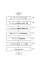
- FIG. 2 is a process diagram illustrating the method for manufacturing the battery pack according to the embodiment.
- 3 to 6 are diagrams for explaining a method of manufacturing the battery pack according to the embodiment.
- the method for manufacturing the battery pack 1 according to the embodiment includes steps S1 to S7.
- step S1 the casing 20, the counterweight 31 to the counterweight 33, the bolt B2, and the bolt B3 are prepared.
- the housing 20 and the counterweight 31 to the counterweight 33 are prepared in a state before being painted.
- the main body 21 of the housing 20 is prepared in a state of being joined and integrated with the counterweight 31 by welding.
- the lid body 22 of the housing 20 is prepared in a state separate from the main body 21.
- step S2 the counterweight 32 is fastened to the front wall portion 26 by a plurality of bolts B2.
- the counterweight 33 is fastened to the rear wall portion 28 by a plurality of bolts B3.
- the counterweight 32 is disposed on the outer surface 26b so that the screw hole 32b overlaps the through hole 26c when viewed from the Y direction.
- the bolt B2 is inserted from the inner surface 26a side into the through hole 26c and screwed into the screw hole 32b.
- the counterweight 33 is arranged on the outer surface 28b so that the screw hole 33b overlaps the through hole 28c when viewed from the Y direction.
- the bolt B3 is inserted into the through hole 28c from the inner surface 28a side and screwed into the screw hole 33b.
- step S ⁇ b> 3 the counter weight 32 is welded to the front wall portion 26 in a state where the counter weight 32 is fastened to the front wall portion 26.
- the counterweight 33 is welded to the rear wall portion 28 in a state where the counterweight 33 is fastened to the rear wall portion 28.
- the counterweight 32 and the front wall part 26 are joined and integrated by the welding part W3.
- the counterweight 33 and the rear wall portion 28 are joined and integrated by a welded portion W4.
- step S4 the casing 20, the counterweight 31 to the counterweight 33, and the welded portions W1 to W4 are coated with paint.
- the counterweight 32 is fastened to the front wall portion 26 and the coating is performed in a state where the counterweight 32 is welded to the front wall portion 26.
- the counterweight 33 is fastened to the rear wall portion 28, and coating is performed in a state where the counterweight 33 is welded to the rear wall portion 28.
- a masking member C1 is inserted in advance into the screw hole 27a before painting.
- the masking member C2 is inserted through the through hole 28d in advance.
- the masking member C1 is a columnar member having an outer diameter equivalent to the inner diameter of the screw hole 27a.
- the masking member C1 prevents the paint from entering the screw hole 27a.
- the masking member C2 is a columnar member having an outer diameter equivalent to the inner diameter of the through hole 28d.
- the masking member C2 prevents the paint from entering the through hole 28d.
- the outer diameters of the masking member C1 and the masking member C2 are the same.
- step S5 the fastening between the counterweight 32 and the front wall portion 26 by the bolt B2 is released. Even after the fastening by the bolt B2 is released, the counterweight 32 and the front wall portion 26 are maintained in an integrated state by the welded portion W3.
- the fastening of the counterweight 33 and the rear wall portion 28 by the plurality of bolts B3 is released. Even after the fastening by the bolt B3 is released, the counterweight 33 and the rear wall portion 28 are maintained in an integrated state by the welded portion W4.
- step S6 the counterweight 32 and the two battery modules 10 are fastened by the bolt B2 through the through hole 26c.
- the counterweight 33 and the two battery modules 10 are fastened by the bolt B3 through the through hole 28c.
- the two battery modules 10 are arranged on the inner surface 26a so that the through hole 12a overlaps the through hole 26c and the screw hole 32b when viewed from the Y direction. Accordingly, the counterweight 32 and the two battery modules 10 are arranged so as to face each other with the front wall portion 26 interposed therebetween. Subsequently, the bolt B2 is inserted into the through hole 12a and the through hole 26c from the inner surface 26a side, and screwed into the screw hole 32b. As a result, the counterweight 32 and the battery module 10 are fastened together with the front wall portion 26.
- the two battery modules 10 are arranged on the inner surface 28a so that the through hole 12a overlaps the through hole 28c and the screw hole 33b when viewed from the Y direction. Accordingly, the counterweight 33 and the two battery modules 10 are arranged so as to face each other with the rear wall portion 28 interposed therebetween. Subsequently, the bolt B3 is inserted into the through hole 12a and the through hole 28c from the inner surface 28a side, and screwed into the screw hole 33b. As a result, the counterweight 33 and the battery module 10 are fastened to the rear wall portion 28 together.
- step S7 the lid body 22 is attached to the main body 21 with the bolt B1.
- the lid 22 is placed on the flange portion 27 side of the main body 21 via the seal member G so that the through hole 28d (see FIG. 1) overlaps with the screw hole 27a (see FIG. 1) when viewed from the Y direction. Deploy.
- the bolt B1 is inserted from the outside of the accommodation space S into the through hole 28d and screwed into the screw hole 27a.
- the lid body 22 and the main body 21 are integrated in a state where the sealing member G is sandwiched between the lid body 22 and the main body 21. Thereby, the battery pack 1 (refer FIG. 1) is manufactured.
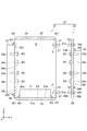
- FIG. 7 is a cross-sectional view showing a battery pack according to a comparative example.
- the battery pack 100 is different from the battery pack 1 in that the counterweight 32 is not welded to the front wall portion 26 and the counterweight 33 is not welded to the rear wall portion 28. (See FIG. 1).
- the battery pack 100 does not include the welded portion W3. That is, the counterweight 32 is attached to the front wall portion 26 only by being fastened to the battery module 10 by the bolt B2. Battery pack 100 does not include welded portion W4. That is, the counterweight 33 is attached to the rear wall portion 28 only by being fastened to the battery module 10 by the bolt B3.
- the inner diameters of the through hole 12a, the through hole 26c, and the through hole 28c are set to sizes that allow the bolt B2 and the bolt B3 to pass therethrough. That is, the inner diameters of the through hole 12a, the through hole 26c, and the through hole 28c are set to a size obtained by adding a margin to the outer diameters of the screw portions of the bolts B2 and B3. Therefore, in the battery pack 100, the counterweight 32 easily slides and moves in the X direction and the Z direction with respect to the front wall portion 26 due to an impact by the margin. Similarly, the counterweight 33 easily slides and moves in the X direction and the Z direction with respect to the rear wall portion 28 due to an impact. As a result, in the battery pack 100, the fastening of the bolt B2 and the bolt B3 may be loosened.
- the counterweight 32 is welded to the front wall portion 26 in addition to being fastened to the battery module 10 by the bolt B2. For this reason, the position of the counterweight 32 is fixed with respect to the front wall portion 26. Thereby, the position of the counterweight 32 does not move in the X direction and the Z direction even by an impact. Therefore, compared with the comparative example, the fastening of the bolt B2 is difficult to loosen.
- the counterweight 33 is welded to the rear wall portion 28 in addition to being fastened to the battery module 10 by the bolt B3. For this reason, the position of the counterweight 33 is fixed with respect to the rear wall portion 28.
- the position of the counterweight 33 does not move in the X direction and the Z direction even by an impact. Therefore, compared with the comparative example, the fastening of the bolt B3 is difficult to loosen. As a result, the impact resistance of the battery pack 1 can be improved.
- the housing 20 is separate from the counterweight 31 to the counterweight 33. Therefore, thin plates can be used for the bottom wall portion 23, the upper wall portion 24, the pair of side wall portions 25, the front wall portion 26, the flange portion 27, and the rear wall portion 28 that constitute the housing 20.
- welding time is shortened, so that the thickness of a member is thin. Thereby, it is hard to produce a difference in the quality of a junction part. Therefore, in the battery pack 1, the welding operation when forming the main body 21 of the casing 20 is facilitated.
- the battery module 10 and the counterweight 32 are fastened together with the front wall portion 26 with bolts B2. Therefore, the required number of bolts and the required number of through holes provided in the front wall portion 26 can be reduced.
- the battery module 10 and the counterweight 33 are fastened to the rear wall portion 28 by bolts B3. Therefore, the required number of bolts and the required number of through holes provided in the rear wall portion 28 can be reduced. Thereby, the structure of the battery pack 1 can be simplified.
- the counter weight 32 and the counter weight 33 also function as a heat radiating unit that releases heat generated in the battery module 10 to the outside.
- the counterweight 32 and the counterweight 33 also as the heat radiating portion, it is not necessary to further provide the heat radiating portion in the vehicle on which the battery pack 1 is mounted. Thereby, the increase in a number of parts can be suppressed.
- the counterweight 32 is welded to the front wall portion 26 in a state where the counterweight 32 is fastened to the front wall portion 26.
- the counterweight 33 is welded to the rear wall portion 28 in a state where the counterweight 33 is fastened to the rear wall portion 28.
- warpage is likely to occur due to heat generated by welding.
- the front wall portion 26 is in close contact with the counterweight 32 by fastening. For this reason, the front wall portion 26 is easily kept in a shape along the counterweight 32.
- the rear wall portion 28 is strongly in close contact with the counterweight 33 by fastening. For this reason, the rear wall portion 28 is easily kept in a shape along the counterweight 33. Thereby, the curvature of the front wall part 26 and the rear wall part 28 by welding can be suppressed.
- the method of manufacturing the battery pack 1 according to the embodiment, warping of the front wall portion 26 and the rear wall portion 28 can be suppressed. Accordingly, the counterweight 32 and the front wall portion 26 are maintained in close contact with each other. The counterweight 33 and the rear wall portion 28 are kept in close contact with each other. For this reason, the heat of the battery module 10 is easily transmitted to the counterweight 32 and the counterweight 33. As a result, a decrease in heat dissipation of the battery module 10 can be suppressed.
- the counterweight 31 and the bottom wall portion 23 are coated at the same time in an integrated state. For this reason, compared with the case where the counterweight 31 and the bottom wall part 23 are painted separately, the painting operation can be facilitated. As a result, in the battery pack 1, the covering region 23r of the housing 20 and the facing surface 31a of the counterweight 31 are not painted. Therefore, the cost of the paint can be suppressed.
- the counterweight 32 and the front wall portion 26 are coated in the integrated state at the same time. For this reason, compared with the case where the counterweight 32 and the front wall part 26 are painted separately, the painting operation can be facilitated. As a result, in the battery pack 1, the covering region 26r of the housing 20 and the facing surface 32a of the counterweight 32 are not painted. Therefore, the cost of the paint can be suppressed.
- the counterweight 33 and the rear wall portion 28 are coated at the same time in an integrated state. For this reason, compared with the case where the counterweight 33 and the rear wall part 28 are painted separately, the painting work can be facilitated. As a result, in the battery pack 1, the covering region 28r of the housing 20 and the facing surface 33a of the counterweight 33 are not painted. Therefore, the cost of the paint can be suppressed.
- step S2 the counterweight 32 is fastened to the front wall portion 26 by the bolt B2 through the through hole 26c. Therefore, it is not necessary to separately prepare a through hole and a bolt for fixing the counterweight 32 to the front wall portion 26 other than the through hole 26c and the bolt B2.
- the counterweight 33 is fastened to the rear wall portion 28 by a bolt B3 through the through hole 28c. Therefore, it is not necessary to separately prepare a through hole and a bolt for fixing the counterweight 33 to the rear wall portion 28 other than the through hole 28c and the bolt B3.
- step S4 in which the casing 20, the counterweight 31 to the counterweight 33, and the welded portions W1 to W4 are coated with paint
- the counterweight 32 is attached to the front wall portion 26 with the bolt B2. Painted in a state of being fastened by. That is, painting is performed with the bolt B2 inserted through the through hole 26c and screwed into the screw hole 32b. For this reason, in the battery pack 1, the inner surfaces of the through hole 26c and the screw hole 32b are not painted.
- the bolt B2 can also function as a masking member for the through hole 26c and the screw hole 32b. For this reason, it is not necessary to provide a masking member separately.
- the counterweight 33 is painted in a state of being fastened to the rear wall portion 28 with the bolt B3. That is, the coating is performed with the bolt B3 inserted into the through hole 28c and screwed into the screw hole 33b. For this reason, in the battery pack 1, the inner surfaces of the through hole 28c and the screw hole 33b are not painted. In this way, the bolt B3 can also function as a masking member for the through hole 28c and the screw hole 33b. For this reason, it is not necessary to provide a masking member separately.
- the present invention is not limited to the above embodiment.
- the present invention may be modified without departing from the gist described in each claim or applied to others.
- the battery pack 1 may be manufactured by a manufacturing method different from the manufacturing method of the battery pack 1 according to the embodiment.
- step S1 the housing 20 and the counterweight 31 to the counterweight 33 may be prepared in a state after being painted.
- the manufacturing method of the battery pack 1 can omit the step S4 of painting the casing 20, the counterweight 31 to the counterweight 33, and the welded portions W1 to W4.
- the covering region 23r, the covering region 26r, the covering region 28r, and the facing surfaces 31a to 33a may be painted.
- the bracket 12 may be provided with screw holes instead of the through holes 12a, and the counterweight 32 and the counterweight 33 may be provided with through holes instead of the screw holes 32b and the screw holes 33b.
- the bolt B ⁇ b> 2 is inserted from the outside of the accommodation space S into the through hole of the counterweight 32 and screwed into the screw hole of the bracket 12.
- the bolt B ⁇ b> 3 is inserted from the outside of the accommodation space S into the through hole of the counterweight 33 and is screwed into the screw hole of the bracket 12.
- the counterweight 32 may be attached to any one of the pair of side wall portions 25 instead of the front wall portion 26.
- the counterweight 33 may be attached to any one of the pair of side wall portions 25 instead of the rear wall portion 28.
- step S2 of fastening the counterweight 32 to the front wall portion 26 and fastening the counterweight 33 to the rear wall portion 28 bolts of the same size as the bolt B2 and bolt B3 are used instead of the bolt B2 and bolt B3. May be.
- SYMBOLS 1 Battery pack, 10 ... Battery module, 20 ... Case, 26 ... Front wall part, 28 ... Rear wall part, 26c, 28c ... Through-hole, 26r, 28r ... Covering area, 32, 33 ... Counterweight, 32a, 33a ... opposing surfaces, B2, B3 ... bolts (fastening members).
Landscapes
- Chemical & Material Sciences (AREA)
- Chemical Kinetics & Catalysis (AREA)
- Electrochemistry (AREA)
- General Chemical & Material Sciences (AREA)
- Battery Mounting, Suspending (AREA)
Abstract
電池パックは、電池モジュールと、筐体と、カウンタウェイトと、締結部材と、を備える。筐体は、貫通孔が設けられた壁部を有し、電池モジュールを収容する。カウンタウェイトは、壁部に溶接されている。締結部材は、壁部を介して互いに対向して配置された電池モジュールとカウンタウェイトとを、貫通孔を介して締結する。
Description
本発明は、電池パック及び電池パックの製造方法に関する。
電気自動車及びフォークリフト等の車両のバッテリーとして使用される電池パックが知られている。例えば、特許文献1には、電池セルを有する電池モジュールと、電池モジュールを内部に収容する筐体と、を備える電池パックが開示されている。特許文献1に記載の電池パックでは、筐体は、所定の厚さを有し、カウンタウェイトとして機能している。
上述のような電池パックの筐体は、複数の部材を溶接により接合することによって形成されることが多い。しかしながら、溶接により部材同士を接合する場合、部材の厚さが厚いほど溶接時間が長くなる。これにより、接合部の品質に差が生じ易い。そこで、筐体を薄板で形成し、薄板を挟んで、カウンタウェイトと電池モジュールとをボルト等の締結部材で締結することが考えられる。しかしながら、この場合、衝撃により締結部材の軸方向に交差する方向にカウンタウェイト及び電池モジュールが移動する可能性がある。その結果、ボルトの締結が緩む可能性がある。
本発明は、製造を容易化でき、且つ耐衝撃性を向上させる電池パック及び電池パックの製造方法を提供する。
本発明の一側面に係る電池パックは、電池モジュールと、筐体と、カウンタウェイトと、締結部材とを備える。筐体は、貫通孔が設けられた壁部を有し、電池モジュールを収容する。カウンタウェイトは、壁部に溶接されている。締結部材は、壁部を介して互いに対向して配置された電池モジュールとカウンタウェイトとを、貫通孔を介して締結する。
この電池パックでは、筐体はカウンタウェイトと別体である。このため、筐体を薄板で形成することができる。したがって、筐体を形成する際の溶接作業が容易となる。この結果、電池パックの製造を容易化できる。カウンタウェイトは、締結部材により貫通孔を介して電池モジュールと締結されている。加えて、カウンタウェイトは、筐体の壁部に溶接されている。このため、カウンタウェイトの位置が壁部に対して固定される。これにより、衝撃によっても、カウンタウェイトが締結部材の軸方向に交差する方向に移動しない。したがって、締結部材の締結が緩み難い。この結果、電池パックの耐衝撃性を向上させることが可能となる。
カウンタウェイトは、壁部と対向する対向面を有してもよい。壁部は、対向面により覆われる被覆領域を有してもよい。対向面及び被覆領域のそれぞれは、塗装されていなくてもよい。この場合、カウンタウェイトと壁部とを一体化した状態で同時に塗装することができる。したがって、カウンタウェイトと壁部とを別々に塗装する場合に比べて、塗装作業を容易化できる。
本発明の別の側面に係る電池パックの製造方法は、筐体の壁部に、カウンタウェイトを締結する工程と、カウンタウェイトが壁部に締結された状態で、カウンタウェイトを壁部に溶接する工程と、カウンタウェイトが壁部に溶接された状態で、壁部を介して電池モジュールをカウンタウェイトと対向して配置し、カウンタウェイトと電池モジュールとを壁部に設けられた貫通孔を介して締結部材により締結する工程と、を含む。
この電池パックの製造方法では、締結により壁部がカウンタウェイトに強く密接する。このため、壁部はカウンタウェイトに沿った形状に保たれ易い。これにより、溶接による壁部の反りを抑制することが可能となる。
この電池パックの製造方法は、壁部にカウンタウェイトが締結されるとともに壁部にカウンタウェイトが溶接された状態で、壁部及びカウンタウェイトを塗装する工程を更に含んでもよい。この場合、カウンタウェイトと壁部とを一体化した状態で同時に塗装する。このため、カウンタウェイトと壁部とを別々に塗装する場合に比べて、塗装作業を容易化できる。
壁部にカウンタウェイトを締結する工程において、貫通孔を介して壁部にカウンタウェイトを締結部材により締結してもよい。この場合、溶接のための締結用に、貫通孔及び締結部材を別途用意する必要がない。このため、製造を容易化できる。
本発明の種々の側面によれば、製造を容易化でき、且つ耐衝撃性を向上させることが可能となる。
以下、添付図面を参照しながら本発明の実施形態が詳細に説明される。図面の説明において、同一または同等の要素には同一符号が用いられ、重複する説明は省略される。
まず、図1を参照して、実施形態に係る電池パックについて説明する。図1は、実施形態に係る電池パックを示す断面図である。図1に示されるように、電池パック1は、電池モジュール10と、筐体20と、カウンタウェイト31~カウンタウェイト33と、ボルトB1~ボルトB3と、溶接部W1~溶接部W4と、を備えている。電池パック1は、例えば電気自動車及びフォークリフト等の車両のバッテリーとして使用される装置である。
電池モジュール10は、複数の電池セル(不図示)、一対のエンドプレート11、及び一対のブラケット12を有している。電池モジュール10の重量は、例えば、20kg以上である。電池セルは、リチウムイオン二次電池等の非水電解質二次電池といった蓄電池、または電気二重層キャパシタ等である。複数の電池セルは、互いに電気的に接続された状態で、所定の方向(X方向)に配列されている。一対のエンドプレート11は、このように配列された複数の電池セルのX方向の両側に配置されている。一対のエンドプレート11は、複数の電池セルを互いに固定し、一体化している。
ブラケット12は、複数の電池セルを筐体20に固定して取り付けるための部材である。ブラケット12は、複数の電池セルのX方向の両側で、エンドプレート11に取り付けられている。ブラケット12は、例えば、ボルト(不図示)でエンドプレート11に取り付けられている。ブラケット12には、複数の貫通孔12aが設けられている。複数の貫通孔12aには、ボルトB2及びボルトB3がY方向に挿通されている。これにより電池モジュール10が前壁部26及び後壁部28に固定されている。
筐体20は、全体として略直方体を呈する箱体である。筐体20は、筐体20の内部の収容空間Sに電池モジュール10を収容している。本実施形態では、筐体20は、例えば、4つの電池モジュール10を収容空間Sに収容している。筐体20のX方向の長さは、例えば、1000mmである。筐体20のX方向に直交するY方向の長さは、例えば、400mmである。筐体20のX方向及びY方向に直交するZ方向の長さは、例えば、600mmである。筐体20は、例えば、厚さが1mm以上20mm以下(好ましくは、1mm以上10mm以下)の薄板により形成されている。筐体20を形成する薄板の材料は、例えば、SS400及びSPHC等の一般的な鋼材である。
筐体20は、開口Aが設けられた本体21と、開口Aを覆う蓋体22と、を有している。本体21は、底壁部23と、上壁部24と、一対の側壁部25と、前壁部26と、フランジ部27と、を含んでいる。本体21は、溶接部W1により一体化されている。蓋体22は、後壁部28を含んでいる。
底壁部23と上壁部24とは、互いに同形状である。底壁部23と上壁部24とは、Z方向で対向する矩形状の薄板である。底壁部23は、内面23aを有している。内面23aは、被覆領域23rを含んでいる。被覆領域23rは、後述の対向面31aにより覆われる領域である。一対の側壁部25は、互いに同形状である。一対の側壁部25は、X方向で対向する矩形状の薄板である。
前壁部26と後壁部28とは、互いに同形状である。前壁部26と後壁部28とは、Y方向で対向する矩形状の薄板である。前壁部26は、内面26a及び外面26bを有している。外面26bは、被覆領域26rを含んでいる。被覆領域26rは、後述の対向面32aにより覆われる領域である。後壁部28は、内面28a及び外面28bを有している。外面28bは、被覆領域28rを含んでいる。被覆領域28rは、後述の対向面33aにより覆われる領域である。
フランジ部27は、矩形枠状の薄板である。フランジ部27は、底壁部23、上壁部24、及び一対の側壁部25の後壁部28側の端部において、収容空間Sに向かって立設されている。フランジ部27の内縁は、開口Aを規定している。フランジ部27の幅(フランジ部27の外縁と内縁とがなす幅)は、例えば、30mmである。フランジ部27は、後壁部28とY方向で対向している。
前壁部26には、複数の貫通孔26cが設けられている。貫通孔26cは、貫通孔12aとY方向から見て重なる位置に設けられている。貫通孔26cは、電池モジュール10を前壁部26に固定するための孔である。貫通孔26cには、ボルトB2がY方向に挿通されている。
後壁部28には、複数の貫通孔28c及び複数の貫通孔28dが設けられている。貫通孔28dは、本体21に蓋体22を固定するための孔である。貫通孔28dは、後壁部28の周縁部に設けられている。後壁部28の周縁部は、フランジ部27とY方向で対向する部分である。貫通孔28cは、電池モジュール10を後壁部28に固定するための孔である。貫通孔28cは、後壁部28の周縁部により囲まれる中央部に設けられている。貫通孔28cは、Y方向から見て貫通孔12aと重なる位置に配置されている。貫通孔28cには、ボルトB3がY方向に挿通されている。
フランジ部27には、複数のネジ穴27aが設けられている。ネジ穴27aは、本体21に蓋体22を固定するための孔である。ネジ穴27aは、Y方向から見て貫通孔28dと重なる位置に設けられている。ネジ穴27aは、フランジ部27を貫通していてもよい。貫通孔28d及びネジ穴27aには、ボルトB1がY方向に挿通されている。
後壁部28は、シール部材Gを介して、ボルトB1によりフランジ部27に取り付けられている。後壁部28は、開口Aを覆っている。シール部材Gは、例えば、矩形環状のガスケットである。シール部材Gは、後壁部28及びフランジ部27により挟持されている。シール部材Gは、収容空間Sを気密に保っている。
カウンタウェイト31は、略直方体を呈し、底壁部23の内面23aに溶接されている。言い換えると、カウンタウェイト31と底壁部23とは、溶接部W2により一体化されている。カウンタウェイト31のX方向の長さは、例えば、950mmである。カウンタウェイト31のY方向の長さは、例えば、350mmである。カウンタウェイト31のZ方向の長さは、例えば、50mmである。カウンタウェイト31の重量は、例えば、40kgである。カウンタウェイト31は、底壁部23の内面23aと対向する対向面31aを有している。
カウンタウェイト32は、略直方体を呈している。カウンタウェイト32は、前壁部26の外面26bに溶接されている。言い換えると、カウンタウェイト32と前壁部26とは、溶接部W3により一体化されている。カウンタウェイト32のX方向の長さは、例えば、950mmである。カウンタウェイト32のY方向の長さは、例えば、50mmである。カウンタウェイト32のZ方向の長さは、例えば、530mmである。カウンタウェイト32の重量は、例えば、40kgである。
カウンタウェイト32は、前壁部26の外面26bと対向する対向面32aを有している。対向面32aには、複数のネジ穴32bが設けられている。ネジ穴32bは、電池モジュール10を前壁部26に固定するための孔である。ネジ穴32bは、Y方向から見て貫通孔12a及び貫通孔26cと重なる位置に配置されている。カウンタウェイト32は、前壁部26を介して電池モジュール10と互いに対向して配置されている。ネジ穴32bには、ボルトB2が螺合されている。カウンタウェイト32は、ボルトB2により、電池モジュール10と締結されている。
カウンタウェイト33は、略直方体を呈している。カウンタウェイト33は、後壁部28の外面28bに溶接されている。言い換えると、カウンタウェイト33と後壁部28とは、溶接部W4により一体化されている。カウンタウェイト33のX方向の長さは、例えば、900mmである。カウンタウェイト33のY方向の長さは、例えば、50mmである。カウンタウェイト33のZ方向の長さは、例えば、500mmである。カウンタウェイト33の重量は、例えば、40kgである。
カウンタウェイト33は、後壁部28の外面28bと対向する対向面33aを有している。対向面33aには、複数のネジ穴33bが設けられている。ネジ穴33bは、電池モジュール10を後壁部28に固定するための孔である。ネジ穴33bは、Y方向から見て貫通孔12a及び貫通孔28cと重なる位置に配置されている。カウンタウェイト33は、後壁部28を介して電池モジュール10と互いに対向して配置されている。ネジ穴33bには、ボルトB3が螺合されている。カウンタウェイト33は、ボルトB3により、電池モジュール10と締結されている。
ボルトB1は、貫通孔28dに挿通され、ネジ穴27aに螺合されている。ボルトB1は、後壁部28とフランジ部27とを締結している。ボルトB2は、貫通孔12a及び貫通孔26cに挿通され、ネジ穴32bに螺合されている。ボルトB2は、前壁部26を介して電池モジュール10とカウンタウェイト32とを締結している。ボルトB3は、貫通孔12a及び貫通孔28cに挿通され、ネジ穴33bに螺合されている。ボルトB3は、後壁部28を介して電池モジュール10とカウンタウェイト33とを締結している。ここでは、ボルトB2及びボルトB3のサイズは同等である。
溶接部W1~溶接部W4は、溶接により形成される部分である。溶接部W1は、本体21を一体化している。溶接部W2は、カウンタウェイト31と底壁部23とを接合している。溶接部W2は、対向面31a及び被覆領域23rの周縁全体に設けられてもよいし、スポット溶接により部分的に設けられてもよい。
溶接部W3は、カウンタウェイト32と前壁部26とを接合している。溶接部W3は、対向面32a及び被覆領域26rの周縁全体に設けられてもよいし、スポット溶接により部分的に設けられてもよい。溶接部W4は、カウンタウェイト33と後壁部28とを接合している。溶接部W4は、対向面33a及び被覆領域28rの周縁全体に設けられてもよいし、スポット溶接により部分的に設けられてもよい。
筐体20、カウンタウェイト31~カウンタウェイト33、及び溶接部W1~溶接部W4は、塗装されている。ただし、筐体20の被覆領域23r、被覆領域26r、被覆領域28r、貫通孔26cの内面、貫通孔28cの内面、貫通孔28dの内面、及びネジ穴27aの内面は、塗装されていない。カウンタウェイト31の対向面31aは、塗装されていない。カウンタウェイト32の対向面32a及びネジ穴32bの内面は、塗装されていない。カウンタウェイト33の対向面33a及びネジ穴33bの内面は、塗装されていない。
次に、図2~図6を参照して、実施形態に係る電池パック1の製造方法について説明する。図2は、実施形態に係る電池パックの製造方法を示す工程図である。図3~図6は、実施形態に係る電池パックの製造方法を説明する図である。
図2に示されるように、実施形態に係る電池パック1の製造方法は、工程S1~工程S7を含んでいる。
図3に示されるように、工程S1では、筐体20、カウンタウェイト31~カウンタウェイト33、ボルトB2、及びボルトB3が準備される。具体的には、筐体20、及びカウンタウェイト31~カウンタウェイト33は、塗装される前の状態で準備される。筐体20の本体21は、カウンタウェイト31と溶接により接合されて一体化された状態で準備される。筐体20の蓋体22は、本体21とは別体の状態で準備される。
図4に示されるように、工程S2では、カウンタウェイト32が、複数のボルトB2により前壁部26に締結される。カウンタウェイト33が、複数のボルトB3により後壁部28に締結される。具体的には、Y方向から見てネジ穴32bが貫通孔26cに重なるように、カウンタウェイト32を外面26bに配置する。続いて、ボルトB2を内面26a側から貫通孔26cに挿通し、そしてネジ穴32bに螺合する。Y方向から見てネジ穴33bが貫通孔28cに重なるように、カウンタウェイト33を外面28bに配置する。続いて、ボルトB3を内面28a側から貫通孔28cに挿通し、そしてネジ穴33bに螺合する。
同じく図4に示されるように、工程S3では、カウンタウェイト32が前壁部26に締結された状態で、カウンタウェイト32が前壁部26に溶接される。カウンタウェイト33が後壁部28に締結された状態で、カウンタウェイト33が後壁部28に溶接される。これにより、カウンタウェイト32と前壁部26とは、溶接部W3で接合されて一体化される。カウンタウェイト33と後壁部28とは、溶接部W4で接合されて一体化される。
図5に示されるように、工程S4では、筐体20、カウンタウェイト31~カウンタウェイト33、及び溶接部W1~溶接部W4が塗料により塗装される。具体的には、前壁部26にカウンタウェイト32が締結されるとともに、前壁部26にカウンタウェイト32が溶接された状態で塗装が行われる。後壁部28にカウンタウェイト33が締結されるとともに、後壁部28にカウンタウェイト33が溶接された状態で塗装が行われる。
更に、工程S4では、塗装前にネジ穴27aには、予めマスキング部材C1が挿入される。貫通孔28dには、予めマスキング部材C2が挿通される。マスキング部材C1は、ネジ穴27aの内径と同等の外径を有する円柱状部材である。マスキング部材C1により、塗料がネジ穴27aに浸入することが抑制される。マスキング部材C2は、貫通孔28dの内径と同等の外径を有する円柱状部材である。マスキング部材C2により、塗料が貫通孔28dに浸入することが抑制される。ここでは、マスキング部材C1及びマスキング部材C2の外径は同等である。
工程S5では、ボルトB2によるカウンタウェイト32と前壁部26との締結が解除される。ボルトB2による締結が解除された後も、カウンタウェイト32と前壁部26とは、溶接部W3により一体化された状態に維持される。複数のボルトB3によるカウンタウェイト33と後壁部28との締結が解除される。ボルトB3による締結が解除された後も、カウンタウェイト33と後壁部28とは、溶接部W4により一体化された状態に維持される。
図6に示されるように、工程S6では、カウンタウェイト32と2つの電池モジュール10とが貫通孔26cを介してボルトB2により締結される。カウンタウェイト33と2つの電池モジュール10とが貫通孔28cを介してボルトB3により締結される。
具体的には、Y方向から見て貫通孔12aが貫通孔26c及びネジ穴32bと重なるように、2つの電池モジュール10を内面26aに配置する。これにより、カウンタウェイト32と2つの電池モジュール10とが、前壁部26を介して互いに対向するように配置された状態となる。続いて、ボルトB2を内面26a側から貫通孔12a及び貫通孔26cに挿通し、そしてネジ穴32bに螺合する。これにより、前壁部26にカウンタウェイト32と電池モジュール10とが共締めされた状態となる。
Y方向から見て貫通孔12aが貫通孔28c及びネジ穴33bと重なるように、2つの電池モジュール10を内面28aに配置する。これにより、カウンタウェイト33と2つの電池モジュール10とが、後壁部28を介して互いに対向するように配置された状態となる。続いて、ボルトB3を内面28a側から貫通孔12a及び貫通孔28cに挿通し、そしてネジ穴33bに螺合する。これにより、後壁部28にカウンタウェイト33と電池モジュール10とが共締めされた状態となる。
同じく図6に示されるように、工程S7では、蓋体22が、ボルトB1により本体21に取り付けられる。具体的には、Y方向から見て貫通孔28d(図1参照)がネジ穴27a(図1参照)と重なるように、蓋体22を本体21のフランジ部27側にシール部材Gを介して配置する。続いて、ボルトB1を収容空間Sの外側から貫通孔28dに挿通し、そしてネジ穴27aに螺合する。このとき、蓋体22と本体21とは、蓋体22と本体21との間にシール部材Gを挟持した状態で一体化される。これにより、電池パック1(図1参照)が製造される。
次に、比較例と比較しながら本実施形態の効果を説明する。図7は、比較例に係る電池パックを示す断面図である。図7に示されるように、電池パック100は、カウンタウェイト32が前壁部26に溶接されていない点、及び、カウンタウェイト33が後壁部28に溶接されていない点で、電池パック1(図1参照)と相違している。
電池パック100は、溶接部W3を備えていない。つまり、カウンタウェイト32は、ボルトB2により電池モジュール10と締結されていることのみで、前壁部26に取り付けられている。電池パック100は、溶接部W4を備えていない。つまり、カウンタウェイト33は、ボルトB3により電池モジュール10と締結されていることのみで、後壁部28に取り付けられている。
貫通孔12a、貫通孔26c及び貫通孔28cの内径は、ボルトB2及びボルトB3が貫通可能なサイズに設定されている。即ち、貫通孔12a、貫通孔26c及び貫通孔28cの内径は、ボルトB2及びボルトB3のネジ部分の外径に余裕代を足した大きさに設定されている。したがって、電池パック100では、余裕代の分だけ、カウンタウェイト32が、衝撃により前壁部26に対してX方向及びZ方向に滑って移動し易い。同様に、カウンタウェイト33が、衝撃により後壁部28に対してX方向及びZ方向に滑って移動し易い。この結果、電池パック100では、ボルトB2及びボルトB3の締結が緩む可能性がある。
これに対して、実施形態に係る電池パック1では、カウンタウェイト32は、ボルトB2により電池モジュール10と締結されていることに加え、前壁部26に溶接されている。このため、カウンタウェイト32の位置が前壁部26に対して固定される。これにより、衝撃によってもカウンタウェイト32の位置がX方向及びZ方向に移動しない。したがって、比較例と比較して、ボルトB2の締結が緩み難い。カウンタウェイト33は、ボルトB3により電池モジュール10と締結されていることに加え、後壁部28に溶接されている。このため、カウンタウェイト33の位置が後壁部28に対して固定される。これにより、衝撃によってもカウンタウェイト33の位置がX方向及びZ方向に移動しない。したがって、比較例と比較して、ボルトB3の締結が緩み難い。この結果、電池パック1の耐衝撃性を向上させることが可能となる。
電池パック1では、筐体20はカウンタウェイト31~カウンタウェイト33と別体である。したがって、筐体20を構成する底壁部23、上壁部24、一対の側壁部25、前壁部26、フランジ部27及び後壁部28として、いずれも薄板を用いることができる。溶接により部材同士を接合する場合、部材の厚さが薄いほど溶接時間が短くなる。これにより、接合部の品質に差が生じ難い。したがって、電池パック1では、筐体20の特に本体21を形成する際の溶接作業が容易となる結果、電池パック1の製造を容易化できる。
電池パック1では、電池モジュール10とカウンタウェイト32とは、ボルトB2により、前壁部26に共締めされている。したがって、ボルトの必要数、及び、前壁部26に設けられる貫通孔の必要数をそれぞれ減らすことができる。電池モジュール10とカウンタウェイト33とは、ボルトB3により、後壁部28に共締めされている。したがって、ボルトの必要数、及び、後壁部28に設けられる貫通孔の必要数をそれぞれ減らすことができる。これにより、電池パック1の構成を簡易化することができる。
電池パック1では、カウンタウェイト32及びカウンタウェイト33は、電池モジュール10で発生した熱を外部に放出する放熱部としても機能している。カウンタウェイト32及びカウンタウェイト33を放熱部と兼用することにより、電池パック1が搭載される車両において、放熱部を更に設ける必要がなくなる。これにより、部品点数の増加を抑制することができる。
電池パック1の製造方法では、カウンタウェイト32を前壁部26に締結した状態で、カウンタウェイト32を前壁部26に溶接する。カウンタウェイト33を後壁部28に締結した状態で、カウンタウェイト33を後壁部28に溶接する。前壁部26及び後壁部28のような薄板の鋼材では、溶接による熱で反りが発生し易い。本実施形態では、前壁部26は締結によりカウンタウェイト32に強く密接する。このため、前壁部26はカウンタウェイト32に沿った形状に保たれ易い。後壁部28は締結によりカウンタウェイト33に強く密接する。このため、後壁部28はカウンタウェイト33に沿った形状に保たれ易い。これにより、溶接による前壁部26及び後壁部28の反りを抑制することができる。
前壁部26に反りが発生すると、カウンタウェイト32と前壁部26との間に隙間が生じる。後壁部28に反りが発生すると、カウンタウェイト33と後壁部28との間に隙間が生じる。このような隙間が生じると、カウンタウェイト32及びカウンタウェイト33に電池モジュール10の熱が伝わり難い。この結果、電池モジュール10の放熱性が低下する場合がある。
上述のように、実施形態に係る電池パック1の製造方法によれば、前壁部26及び後壁部28の反りを抑制することができる。したがって、カウンタウェイト32と前壁部26とが密接した状態に維持される。カウンタウェイト33と後壁部28とが密接した状態に維持される。このため、電池モジュール10の熱がカウンタウェイト32及びカウンタウェイト33に伝わり易い。この結果、電池モジュール10の放熱性の低下を抑制することができる。
電池パック1の製造方法では、カウンタウェイト31と底壁部23とを一体化した状態で同時に塗装する。このため、カウンタウェイト31と底壁部23とを別々に塗装する場合に比べて、塗装作業を容易化できる。その結果、電池パック1では、筐体20の被覆領域23rと、カウンタウェイト31の対向面31aとは、塗装されていない。したがって、塗料のコストを抑制することができる。
電池パック1の製造方法では、カウンタウェイト32と前壁部26とを一体化した状態で同時に塗装する。このため、カウンタウェイト32と前壁部26とを別々に塗装する場合に比べて、塗装作業を容易化できる。その結果、電池パック1では、筐体20の被覆領域26rと、カウンタウェイト32の対向面32aとは、塗装されていない。したがって、塗料のコストを抑制することができる。
電池パック1の製造方法では、カウンタウェイト33と後壁部28とを一体化した状態で同時に塗装する。このため、カウンタウェイト33と後壁部28とを別々に塗装する場合に比べて、塗装作業を容易化できる。その結果、電池パック1では、筐体20の被覆領域28rと、カウンタウェイト33の対向面33aとは、塗装されていない。したがって、塗料のコストを抑制することができる。
工程S2では、カウンタウェイト32は、貫通孔26cを介してボルトB2により前壁部26に締結される。したがって、カウンタウェイト32を前壁部26に固定するための貫通孔及びボルトを貫通孔26c及びボルトB2以外に別途用意する必要がない。カウンタウェイト33は、貫通孔28cを介してボルトB3により後壁部28に締結される。したがって、カウンタウェイト33を後壁部28に固定するための貫通孔及びボルトを貫通孔28c及びボルトB3以外に別途用意する必要がない。
電池パック1の製造方法では、筐体20、カウンタウェイト31~カウンタウェイト33、及び溶接部W1~溶接部W4が塗料により塗装される工程S4において、カウンタウェイト32は、前壁部26にボルトB2により締結された状態で塗装される。即ち、ボルトB2を貫通孔26cに挿通し、そしてネジ穴32bに螺合した状態で塗装が行われる。このため、電池パック1では、貫通孔26c及びネジ穴32bの内面が塗装されていない。このように、ボルトB2を貫通孔26c及びネジ穴32bのマスキング部材としても機能させることができる。このため、マスキング部材を別途設ける必要がない。
カウンタウェイト33は、後壁部28にボルトB3により締結された状態で塗装される。即ち、ボルトB3を貫通孔28cに挿通し、そしてネジ穴33bに螺合した状態で塗装が行われる。このため、電池パック1では、貫通孔28c及びネジ穴33bの内面が塗装されていない。このように、ボルトB3を貫通孔28c及びネジ穴33bのマスキング部材としても機能させることができる。このため、マスキング部材を別途設ける必要がない。
本発明は上記実施形態に限定されない。本発明は、各請求項に記載した要旨を変更しない範囲で変形し、または他のものに適用したものであってもよい。
例えば、電池パック1は、実施形態に係る電池パック1の製造方法とは異なる製造方法により製造されてもよい。
工程S1において、筐体20、及びカウンタウェイト31~カウンタウェイト33は、塗装された後の状態で準備されてもよい。この場合、電池パック1の製造方法は、筐体20、カウンタウェイト31~カウンタウェイト33、及び溶接部W1~溶接部W4を塗装する工程S4を省略することができる。被覆領域23r、被覆領域26r、被覆領域28r、及び対向面31a~対向面33aは、塗装されていてもよい。
ブラケット12に貫通孔12aの代わりにネジ穴が設けられるとともに、カウンタウェイト32及びカウンタウェイト33にネジ穴32b及びネジ穴33bの代わりに貫通孔が設けられていてもよい。この場合、ボルトB2は、収容空間Sの外側から、カウンタウェイト32の貫通孔に挿通され、ブラケット12のネジ穴に螺合される。ボルトB3は、収容空間Sの外側から、カウンタウェイト33の貫通孔に挿通され、ブラケット12のネジ穴に螺合される。
カウンタウェイト32は、前壁部26ではなく、例えば、一対の側壁部25のいずれかに取り付けられてもよい。カウンタウェイト33は、後壁部28ではなく、例えば、一対の側壁部25のいずれかに取り付けられてもよい。
カウンタウェイト32を前壁部26に締結するとともに、カウンタウェイト33を後壁部28に締結する工程S2において、ボルトB2及びボルトB3ではなく、ボルトB2及びボルトB3と同等のサイズの異なるボルトが用いられてもよい。
1…電池パック、10…電池モジュール、20…筐体、26…前壁部、28…後壁部、26c,28c…貫通孔、26r,28r…被覆領域、32,33…カウンタウェイト、32a,33a…対向面、B2,B3…ボルト(締結部材)。
Claims (5)
- 電池モジュールと、
貫通孔が設けられた壁部を有し、前記電池モジュールを収容する筐体と、
前記壁部に溶接されたカウンタウェイトと、
前記壁部を介して互いに対向して配置された前記電池モジュールと前記カウンタウェイトとを、前記貫通孔を介して締結する締結部材と、を備える、電池パック。 - 前記カウンタウェイトは、前記壁部と対向する対向面を有し、
前記壁部は、前記対向面により覆われる被覆領域を有し、
前記対向面及び前記被覆領域のそれぞれは、塗装されていない、請求項1に記載の電池パック。 - 筐体の壁部に、カウンタウェイトを締結する工程と、
前記カウンタウェイトが前記壁部に締結された状態で、前記カウンタウェイトを前記壁部に溶接する工程と、
前記カウンタウェイトが前記壁部に溶接された状態で、前記壁部を介して電池モジュールを前記カウンタウェイトと対向して配置し、前記カウンタウェイトと前記電池モジュールとを前記壁部に設けられた貫通孔を介して締結部材により締結する工程と、を含む、電池パックの製造方法。 - 前記壁部に前記カウンタウェイトが締結されるとともに前記壁部に前記カウンタウェイトが溶接された状態で、前記壁部及び前記カウンタウェイトを塗装する工程を更に含む、請求項3に記載の電池パックの製造方法。
- 前記壁部に前記カウンタウェイトを締結する工程において、前記貫通孔を介して前記壁部に前記カウンタウェイトを前記締結部材により締結する、請求項3又は4に記載の電池パックの製造方法。
Applications Claiming Priority (2)
| Application Number | Priority Date | Filing Date | Title |
|---|---|---|---|
| JP2015243922A JP6607020B2 (ja) | 2015-12-15 | 2015-12-15 | 電池パック及び電池パックの製造方法 |
| JP2015-243922 | 2015-12-15 |
Publications (1)
| Publication Number | Publication Date |
|---|---|
| WO2017104176A1 true WO2017104176A1 (ja) | 2017-06-22 |
Family
ID=59055955
Family Applications (1)
| Application Number | Title | Priority Date | Filing Date |
|---|---|---|---|
| PCT/JP2016/074524 Ceased WO2017104176A1 (ja) | 2015-12-15 | 2016-08-23 | 電池パック及び電池パックの製造方法 |
Country Status (2)
| Country | Link |
|---|---|
| JP (1) | JP6607020B2 (ja) |
| WO (1) | WO2017104176A1 (ja) |
Families Citing this family (3)
| Publication number | Priority date | Publication date | Assignee | Title |
|---|---|---|---|---|
| KR102552521B1 (ko) * | 2018-12-20 | 2023-07-05 | 두산산업차량 주식회사 | 배터리 중량 조절을 위한 모듈 웨이트 유닛 및 이를 이용한 배터리 외함 |
| US12476289B2 (en) * | 2020-11-03 | 2025-11-18 | Blue Line Battery, Inc. | Modular battery |
| KR20250066011A (ko) * | 2023-11-06 | 2025-05-13 | 주식회사 엘지에너지솔루션 | 냉각성능이 향상되는 배터리 모듈 및 이를 포함하는 배터리 팩 |
Citations (4)
| Publication number | Priority date | Publication date | Assignee | Title |
|---|---|---|---|---|
| JPS50132812U (ja) * | 1974-04-17 | 1975-10-31 | ||
| WO2014061401A1 (ja) * | 2012-10-18 | 2014-04-24 | 株式会社 豊田自動織機 | 産業車両 |
| WO2014109002A1 (ja) * | 2013-01-08 | 2014-07-17 | 株式会社小松製作所 | 作業機械用バッテリケース、作業機械用バッテリユニット、バッテリ式作業機械及びバッテリ式フォークリフト |
| JP2014222591A (ja) * | 2013-05-13 | 2014-11-27 | 株式会社豊田自動織機 | 電池パック |
Family Cites Families (1)
| Publication number | Priority date | Publication date | Assignee | Title |
|---|---|---|---|---|
| JP6641764B2 (ja) * | 2015-08-05 | 2020-02-05 | 株式会社豊田自動織機 | 電池パック |
-
2015
- 2015-12-15 JP JP2015243922A patent/JP6607020B2/ja not_active Expired - Fee Related
-
2016
- 2016-08-23 WO PCT/JP2016/074524 patent/WO2017104176A1/ja not_active Ceased
Patent Citations (4)
| Publication number | Priority date | Publication date | Assignee | Title |
|---|---|---|---|---|
| JPS50132812U (ja) * | 1974-04-17 | 1975-10-31 | ||
| WO2014061401A1 (ja) * | 2012-10-18 | 2014-04-24 | 株式会社 豊田自動織機 | 産業車両 |
| WO2014109002A1 (ja) * | 2013-01-08 | 2014-07-17 | 株式会社小松製作所 | 作業機械用バッテリケース、作業機械用バッテリユニット、バッテリ式作業機械及びバッテリ式フォークリフト |
| JP2014222591A (ja) * | 2013-05-13 | 2014-11-27 | 株式会社豊田自動織機 | 電池パック |
Also Published As
| Publication number | Publication date |
|---|---|
| JP6607020B2 (ja) | 2019-11-20 |
| JP2017111899A (ja) | 2017-06-22 |
Similar Documents
| Publication | Publication Date | Title |
|---|---|---|
| JP6015373B2 (ja) | 密閉容器の製造方法 | |
| JP5971117B2 (ja) | 二次電池溶接用治具 | |
| US11186183B2 (en) | Battery carrier with a peripheral frame and adhesive gap set in a defined manner | |
| US10637023B2 (en) | Battery carrier for an electric motor vehicle | |
| JP5652372B2 (ja) | 電池ケース | |
| JP6156727B2 (ja) | 蓄電素子及び蓄電装置 | |
| JP6194300B2 (ja) | 蓄電装置 | |
| JP6607020B2 (ja) | 電池パック及び電池パックの製造方法 | |
| JP2012097896A (ja) | ガスケットを用いたシール構造体 | |
| WO2020135154A1 (zh) | 电池包及用于电池包的框体 | |
| WO2017073416A1 (ja) | 蓄電装置 | |
| WO2018159275A1 (ja) | 電池モジュール | |
| JP2019075329A (ja) | 電装品ケースのシール構造 | |
| US10319957B2 (en) | Energy storage device and energy storage apparatus | |
| JP2010097770A (ja) | 電池筐体、二次電池及び二次電池の製造方法 | |
| WO2021132215A1 (ja) | 蓄電モジュール | |
| JP2016167350A (ja) | 蓄電素子及び蓄電装置 | |
| JP2017220344A (ja) | 電池パック | |
| JP6094880B2 (ja) | 蓄電装置 | |
| JP6416696B2 (ja) | ケース本体と蓋体との溶接方法および該方法を用いた電池の製造方法 | |
| WO2018016136A1 (ja) | 電池パック | |
| KR20140100074A (ko) | 전지 팩 및 전지 팩의 제조방법 | |
| JP6156728B2 (ja) | 蓄電素子及び蓄電装置 | |
| JP2016119156A (ja) | 蓄電素子及び蓄電装置 | |
| JP2022156419A (ja) | 蓄電セル、蓄電装置および蓄電装置の製造方法 |
Legal Events
| Date | Code | Title | Description |
|---|---|---|---|
| 121 | Ep: the epo has been informed by wipo that ep was designated in this application |
Ref document number: 16875163 Country of ref document: EP Kind code of ref document: A1 |
|
| NENP | Non-entry into the national phase |
Ref country code: DE |
|
| 122 | Ep: pct application non-entry in european phase |
Ref document number: 16875163 Country of ref document: EP Kind code of ref document: A1 |