WO2017098983A1 - 成形品の製造方法、及び成形品 - Google Patents
成形品の製造方法、及び成形品 Download PDFInfo
- Publication number
- WO2017098983A1 WO2017098983A1 PCT/JP2016/085633 JP2016085633W WO2017098983A1 WO 2017098983 A1 WO2017098983 A1 WO 2017098983A1 JP 2016085633 W JP2016085633 W JP 2016085633W WO 2017098983 A1 WO2017098983 A1 WO 2017098983A1
- Authority
- WO
- WIPO (PCT)
- Prior art keywords
- molded product
- crystal grains
- metal plate
- tensile deformation
- crystal
- Prior art date
Links
Images


Classifications
-
- B—PERFORMING OPERATIONS; TRANSPORTING
- B21—MECHANICAL METAL-WORKING WITHOUT ESSENTIALLY REMOVING MATERIAL; PUNCHING METAL
- B21D—WORKING OR PROCESSING OF SHEET METAL OR METAL TUBES, RODS OR PROFILES WITHOUT ESSENTIALLY REMOVING MATERIAL; PUNCHING METAL
- B21D22/00—Shaping without cutting, by stamping, spinning, or deep-drawing
- B21D22/20—Deep-drawing
-
- C—CHEMISTRY; METALLURGY
- C21—METALLURGY OF IRON
- C21D—MODIFYING THE PHYSICAL STRUCTURE OF FERROUS METALS; GENERAL DEVICES FOR HEAT TREATMENT OF FERROUS OR NON-FERROUS METALS OR ALLOYS; MAKING METAL MALLEABLE, e.g. BY DECARBURISATION OR TEMPERING
- C21D9/00—Heat treatment, e.g. annealing, hardening, quenching or tempering, adapted for particular articles; Furnaces therefor
- C21D9/46—Heat treatment, e.g. annealing, hardening, quenching or tempering, adapted for particular articles; Furnaces therefor for sheet metals
- C21D9/48—Heat treatment, e.g. annealing, hardening, quenching or tempering, adapted for particular articles; Furnaces therefor for sheet metals deep-drawing sheets
-
- C—CHEMISTRY; METALLURGY
- C21—METALLURGY OF IRON
- C21D—MODIFYING THE PHYSICAL STRUCTURE OF FERROUS METALS; GENERAL DEVICES FOR HEAT TREATMENT OF FERROUS OR NON-FERROUS METALS OR ALLOYS; MAKING METAL MALLEABLE, e.g. BY DECARBURISATION OR TEMPERING
- C21D8/00—Modifying the physical properties by deformation combined with, or followed by, heat treatment
- C21D8/02—Modifying the physical properties by deformation combined with, or followed by, heat treatment during manufacturing of plates or strips
- C21D8/04—Modifying the physical properties by deformation combined with, or followed by, heat treatment during manufacturing of plates or strips to produce plates or strips for deep-drawing
- C21D8/0405—Modifying the physical properties by deformation combined with, or followed by, heat treatment during manufacturing of plates or strips to produce plates or strips for deep-drawing of ferrous alloys
-
- C—CHEMISTRY; METALLURGY
- C22—METALLURGY; FERROUS OR NON-FERROUS ALLOYS; TREATMENT OF ALLOYS OR NON-FERROUS METALS
- C22C—ALLOYS
- C22C38/00—Ferrous alloys, e.g. steel alloys
- C22C38/001—Ferrous alloys, e.g. steel alloys containing N
-
- C—CHEMISTRY; METALLURGY
- C22—METALLURGY; FERROUS OR NON-FERROUS ALLOYS; TREATMENT OF ALLOYS OR NON-FERROUS METALS
- C22C—ALLOYS
- C22C38/00—Ferrous alloys, e.g. steel alloys
- C22C38/002—Ferrous alloys, e.g. steel alloys containing In, Mg, or other elements not provided for in one single group C22C38/001 - C22C38/60
-
- C—CHEMISTRY; METALLURGY
- C22—METALLURGY; FERROUS OR NON-FERROUS ALLOYS; TREATMENT OF ALLOYS OR NON-FERROUS METALS
- C22C—ALLOYS
- C22C38/00—Ferrous alloys, e.g. steel alloys
- C22C38/02—Ferrous alloys, e.g. steel alloys containing silicon
-
- C—CHEMISTRY; METALLURGY
- C22—METALLURGY; FERROUS OR NON-FERROUS ALLOYS; TREATMENT OF ALLOYS OR NON-FERROUS METALS
- C22C—ALLOYS
- C22C38/00—Ferrous alloys, e.g. steel alloys
- C22C38/04—Ferrous alloys, e.g. steel alloys containing manganese
-
- C—CHEMISTRY; METALLURGY
- C22—METALLURGY; FERROUS OR NON-FERROUS ALLOYS; TREATMENT OF ALLOYS OR NON-FERROUS METALS
- C22C—ALLOYS
- C22C38/00—Ferrous alloys, e.g. steel alloys
- C22C38/06—Ferrous alloys, e.g. steel alloys containing aluminium
-
- C—CHEMISTRY; METALLURGY
- C22—METALLURGY; FERROUS OR NON-FERROUS ALLOYS; TREATMENT OF ALLOYS OR NON-FERROUS METALS
- C22C—ALLOYS
- C22C38/00—Ferrous alloys, e.g. steel alloys
- C22C38/12—Ferrous alloys, e.g. steel alloys containing tungsten, tantalum, molybdenum, vanadium, or niobium
-
- C—CHEMISTRY; METALLURGY
- C22—METALLURGY; FERROUS OR NON-FERROUS ALLOYS; TREATMENT OF ALLOYS OR NON-FERROUS METALS
- C22C—ALLOYS
- C22C38/00—Ferrous alloys, e.g. steel alloys
- C22C38/14—Ferrous alloys, e.g. steel alloys containing titanium or zirconium
-
- C—CHEMISTRY; METALLURGY
- C21—METALLURGY OF IRON
- C21D—MODIFYING THE PHYSICAL STRUCTURE OF FERROUS METALS; GENERAL DEVICES FOR HEAT TREATMENT OF FERROUS OR NON-FERROUS METALS OR ALLOYS; MAKING METAL MALLEABLE, e.g. BY DECARBURISATION OR TEMPERING
- C21D2211/00—Microstructure comprising significant phases
- C21D2211/005—Ferrite
-
- C—CHEMISTRY; METALLURGY
- C21—METALLURGY OF IRON
- C21D—MODIFYING THE PHYSICAL STRUCTURE OF FERROUS METALS; GENERAL DEVICES FOR HEAT TREATMENT OF FERROUS OR NON-FERROUS METALS OR ALLOYS; MAKING METAL MALLEABLE, e.g. BY DECARBURISATION OR TEMPERING
- C21D8/00—Modifying the physical properties by deformation combined with, or followed by, heat treatment
- C21D8/02—Modifying the physical properties by deformation combined with, or followed by, heat treatment during manufacturing of plates or strips
- C21D8/0221—Modifying the physical properties by deformation combined with, or followed by, heat treatment during manufacturing of plates or strips characterised by the working steps
- C21D8/0236—Cold rolling
-
- C—CHEMISTRY; METALLURGY
- C22—METALLURGY; FERROUS OR NON-FERROUS ALLOYS; TREATMENT OF ALLOYS OR NON-FERROUS METALS
- C22C—ALLOYS
- C22C38/00—Ferrous alloys, e.g. steel alloys
-
- Y—GENERAL TAGGING OF NEW TECHNOLOGICAL DEVELOPMENTS; GENERAL TAGGING OF CROSS-SECTIONAL TECHNOLOGIES SPANNING OVER SEVERAL SECTIONS OF THE IPC; TECHNICAL SUBJECTS COVERED BY FORMER USPC CROSS-REFERENCE ART COLLECTIONS [XRACs] AND DIGESTS
- Y10—TECHNICAL SUBJECTS COVERED BY FORMER USPC
- Y10T—TECHNICAL SUBJECTS COVERED BY FORMER US CLASSIFICATION
- Y10T428/00—Stock material or miscellaneous articles
- Y10T428/12—All metal or with adjacent metals
- Y10T428/12389—All metal or with adjacent metals having variation in thickness
Definitions
- the present disclosure relates to a method for manufacturing a molded product and a molded product.
- Patent Document 1 discloses that an uneven stripe pattern appears in parallel with the rolling direction (riding). Specifically, Patent Document 1 discloses the following.
- the average Taylor factor calculated from all crystal orientations present in the texture is greatly related to ridging resistance.
- Patent Document 1 Japanese Patent No. 5683193
- Patent Document 1 only shows that ridging is suppressed in the forming process of a metal plate in which a uniaxial tensile deformation in which the rolling width direction is the main strain direction occurs. No consideration is given to the metal plate forming process in which plane strain tensile deformation and biaxial tensile deformation occur, such as deep drawing and stretch forming.
- the products of conventional outer plates of automobiles are produced by limiting the amount of strain applied to the product surface to a processing amount that results in a metal plate thickness reduction rate of less than 10%. That is, there are restrictions on the processing conditions in order to avoid rough skin.
- more complex automotive outer plate product shapes are required, and there is a demand for a method that can achieve both a reduction in the thickness of the metal plate of 10% or more and the suppression of rough skin during forming.
- an object of one embodiment of the present disclosure is to generate plane strain tensile deformation, plane strain tensile deformation, and biaxial tensile deformation on a metal plate having a bcc structure, and at least the metal plate It is to provide a method for producing a molded product in which the occurrence of rough skin is suppressed and a molded product having excellent design properties can be obtained even when a part of the sheet is subjected to a molding process with a thickness reduction rate of 10% to 30%. .
- Another object of one embodiment of the present disclosure is a molded product of a metal plate having a bcc structure and having a shape in which plane strain tensile deformation or plane strain tensile deformation and biaxial tensile deformation occur,
- the maximum thickness of the product is D1 and the minimum thickness of the molded product is D2
- the condition of the formula: 10 ⁇ (D1-D2) / D1 ⁇ 100 ⁇ 30, or the maximum hardness of the molded product is H1
- molding When the minimum hardness of the product is H2, even if it is a molded product that satisfies the condition of the formula: 15 ⁇ (H1 ⁇ H2) / H1 ⁇ 100 ⁇ 40, the occurrence of rough skin is suppressed and the molded product is excellent in design. Is to provide.
- the inventors In order to manufacture a molded product having a complicated shape in recent years, the inventors have determined the surface properties when forming a metal plate with a large processing amount (processing amount that achieves a plate thickness reduction rate of 10% or more of the metal plate). investigated. As a result, the inventors obtained the following knowledge. Under plane strain tensile deformation and biaxial tensile deformation, crystal grains having a crystal orientation within 15 ° from the ⁇ 001 ⁇ plane parallel to the surface of the metal plate having the bcc structure are preferentially deformed and unevenness is developed. Therefore, the inventors focused on the area fraction and average crystal grain size of crystal grains having a crystal orientation within 15 ° from the ⁇ 001 ⁇ plane parallel to the surface of the metal plate. As a result, the inventors have found that a molded product having excellent design properties can be obtained by suppressing the development of irregularities and suppressing the occurrence of rough skin by the area fraction and average crystal grain size of these crystal grains.
- the inventors obtained the following knowledge. Crystal grains other than crystal grains having a crystal orientation within 15 ° from the ⁇ 111 ⁇ plane parallel to the surface of a metal plate having a bcc structure under plane strain tensile deformation or plane strain tensile deformation and biaxial tensile deformation Preferential deformation and unevenness develop. Therefore, the inventors focused on the area fraction of crystal grains other than crystal grains having a crystal orientation within 15 ° from the ⁇ 111 ⁇ plane parallel to the surface of the metal plate. As a result, the inventors have found that, by the area fraction of these crystal grains, it is possible to obtain a molded product that suppresses the development of unevenness, suppresses the occurrence of rough skin, and has an excellent design.
- the gist of the present disclosure is as follows.
- the crystal grains having a crystal orientation within 15 ° from the ⁇ 001 ⁇ plane parallel to the surface of the metal plate have an area fraction of 0.45 or less and an average crystal grain size of 15 ⁇ m or less.
- a metal plate having a bcc structure and satisfying the following condition (A) or (B) on the surface of the metal plate plane strain tensile deformation, plane strain tensile deformation and biaxial tensile deformation occur, and A method for manufacturing a molded product, wherein a molded product is manufactured by performing a molding process in which at least a part of a metal plate has a thickness reduction rate of 10% to 30%.
- the area fraction of crystal grains other than crystal grains having a crystal orientation within 15 ° from the ⁇ 111 ⁇ plane parallel to the surface of the metal plate is 0.25 or more and 0.55 or less.
- the area fraction of crystal grains other than crystal grains having a crystal orientation within 15 ° from the ⁇ 111 ⁇ plane parallel to the surface of the metal plate is 0.55 or less and the average crystal grain size is 15 ⁇ m or less. is there.
- ⁇ 3> The method for producing a molded article according to ⁇ 1> or ⁇ 2>, wherein the metal plate is a steel plate.
- ⁇ 4> The method for producing a molded product according to any one of ⁇ 1> to ⁇ 3>, wherein the metal plate is a ferritic steel plate having a ferrite fraction of 50% or more of the metal structure.
- ⁇ 5> A molded product of a metal plate having a bcc structure and having a shape in which plane strain tensile deformation and biaxial tensile deformation occur, When the maximum thickness of the molded product is D1 and the minimum thickness of the molded product is D2, the condition of the formula: 10 ⁇ (D1-D2) / D1 ⁇ 100 ⁇ 30 is satisfied, A molded product that satisfies the following condition (c) or (d) on the surface of the molded product.
- the area fraction of crystal grains having a crystal orientation within 15 ° from the ⁇ 001 ⁇ plane parallel to the surface of the molded product is 0.20 or more and 0.35 or less.
- the crystal grains having a crystal orientation within 15 ° from the ⁇ 001 ⁇ plane parallel to the surface of the molded product have an area fraction of 0.45 or less and an average crystal grain size of 15 ⁇ m or less.
- a metal plate molded product having a bcc structure and having a plane strain tensile deformation, or a shape in which plane strain tensile deformation and biaxial tensile deformation occur When the maximum thickness of the molded product is D1 and the minimum thickness of the molded product is D2, the condition of the formula: 10 ⁇ (D1-D2) / D1 ⁇ 100 ⁇ 30 is satisfied, A molded product that satisfies the following condition (C) or (D) on the surface of the molded product. (C) The area fraction of crystal grains other than crystal grains having a crystal orientation within 15 ° from the ⁇ 111 ⁇ plane parallel to the surface of the molded product is 0.25 or more and 0.55 or less.
- a molded product of a metal plate having a bcc structure and having a shape in which plane strain tensile deformation and biaxial tensile deformation occur When the maximum hardness of the molded product is H1 and the minimum hardness of the molded product is H2, the condition of the formula: 15 ⁇ (H1 ⁇ H2) / H1 ⁇ 100 ⁇ 40 is satisfied, A molded product that satisfies the following condition (c) or (d) on the surface of the molded product. (C) The area fraction of crystal grains having a crystal orientation within 15 ° from the ⁇ 001 ⁇ plane parallel to the surface of the molded product is 0.20 or more and 0.35 or less.
- the crystal grains having a crystal orientation within 15 ° from the ⁇ 001 ⁇ plane parallel to the surface of the molded product have an area fraction of 0.45 or less and an average crystal grain size of 15 ⁇ m or less.
- a metal plate molded product having a bcc structure and having a plane strain tensile deformation, or a shape in which plane strain tensile deformation and biaxial tensile deformation occur When the maximum hardness of the molded product is H1 and the minimum hardness of the molded product is H2, the condition of the formula: 15 ⁇ (H1 ⁇ H2) / H1 ⁇ 100 ⁇ 40 is satisfied, A molded product that satisfies the following condition (C) or (D) on the surface of the molded product.
- the area fraction of crystal grains other than crystal grains having a crystal orientation within 15 ° from the ⁇ 111 ⁇ plane parallel to the surface of the molded product is 0.25 or more and 0.55 or less.
- the area fraction of crystal grains other than crystal grains having a crystal orientation within 15 ° from the ⁇ 111 ⁇ plane parallel to the surface of the molded product is 0.55 or less and the average crystal grain size is 15 ⁇ m or less. is there.
- plane strain tensile deformation, plane strain tensile deformation, and biaxial tensile deformation occur with respect to a metal plate having a bcc structure, and at least a portion of the metal plate has a thickness reduction rate. Even when a molding process of 10% or more and 30% or less is performed, it is possible to provide a method for producing a molded product in which the occurrence of rough skin is suppressed and a molded product having excellent design properties can be obtained.
- a metal plate molded product having a bcc structure and having a plane strain tensile deformation or a shape in which plane strain tensile deformation and biaxial tensile deformation are generated,
- the maximum thickness of the product is D1 and the minimum thickness of the molded product is D2
- the condition of the formula: 10 ⁇ (D1-D2) / D1 ⁇ 100 ⁇ 30, or the maximum hardness of the molded product is H1
- the minimum hardness of the molded product is H2 even if the molded product satisfies the condition of the formula: 15 ⁇ (H1 ⁇ H2) / H1 ⁇ 100 ⁇ 30, the occurrence of rough skin is suppressed and the design has excellent design. Goods can be provided.
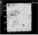
- FIG. 1 is a view obtained by observing the surface of a metal plate after performing a bulge forming test using an SEM.
- FIG. 2 is a diagram in which the surface of a metal plate that has been further electropolished after the bulge forming test was observed using an SEM.
- FIG. 3A is a schematic diagram when the surface of a metal plate with less unevenness developed after a bulge forming test is analyzed by the EBSD method.
- FIG. 3B is a schematic diagram showing surface irregularities of the metal plate in the A1-A2 cross section of FIG. 3A.
- FIG. 4A is a schematic view when the surface of a metal plate with much unevenness developed after the bulge forming test is analyzed by the EBSD method.
- FIG. 1 is a view obtained by observing the surface of a metal plate after performing a bulge forming test using an SEM.
- FIG. 2 is a diagram in which the surface of a metal plate that has been further electropolished after the bulge forming test
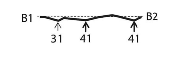
- FIG. 4B is a schematic diagram showing surface irregularities of the metal plate in the B1-B2 cross section of FIG. 4A.
- FIG. 5A is a schematic diagram in the case where the surface of a metal plate with many unevenness development after the bulge forming test is analyzed by the EBSD method.
- FIG. 5B is a schematic diagram showing surface irregularities of the metal plate in the C1-C2 cross section of FIG. 5A. It is a schematic diagram for demonstrating the definition of "the crystal grain which has a crystal orientation within 15 degrees from the ⁇ 001 ⁇ plane parallel to the surface of a metal plate.”
- FIG. 7A is a schematic diagram illustrating an example of an overhang forming process.
- FIG. 7A is a schematic diagram illustrating an example of an overhang forming process.
- FIG. 7B is a schematic view showing an example of a molded product obtained by the stretch forming process shown in FIG. 7A.
- FIG. 8A is a schematic diagram illustrating an example of drawing and forming.
- FIG. 8B is a schematic diagram showing an example of a molded product obtained by the drawing and forming process shown in FIG. 8A.
- FIG. 9 is a schematic diagram for explaining plane strain tensile deformation, biaxial tensile deformation, and uniaxial tensile deformation.
- FIG. 10 is a schematic diagram illustrating a method of obtaining the average crystal grain size of ⁇ 001 ⁇ crystal grains from the analysis result by the EBSD method.
- FIG. 11 is a graph showing an example of the relationship between the plate thickness reduction rate and the processing hardness in the forming process.
- FIG. 12 is a schematic diagram for explaining a molded product produced in the example.
- FIG. 13 is a schematic view of a steel plate observed from above.
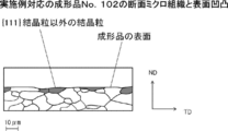
- 14 shows a molded product No. corresponding to the example. It is a schematic diagram which shows 2 cross-sectional microstructures and surface irregularities.
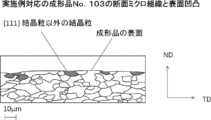
- 15 shows a molded product No. corresponding to the example. It is a schematic diagram which shows the cross-sectional microstructure of 3 and surface asperity.
- 16 shows a molded product No. corresponding to the comparative example. It is a schematic diagram which shows 1 cross-sectional microstructure and surface unevenness
- FIG. 13 is a schematic view of a steel plate observed from above.
- 14 shows a molded product No. corresponding to the example. It is a schematic diagram which shows 2 cross-sectional microstructures and surface irregularities.
- 15 shows a molded product No. corresponding to the example. It is a schematic diagram which shows the cross-sectional microstructure of 3 and surface as
- 17 is a diagram showing the relationship between the result of visual evaluation and the average crystal grain size and crystal grain size of ⁇ 001 ⁇ crystal grains for the molded product obtained in the first example.
- 18 shows a molded product No. corresponding to the example. It is a schematic diagram which shows the cross-sectional microstructure and surface unevenness
- 19 shows a molded product No. corresponding to the example. It is a schematic diagram which shows the cross-sectional microstructure of 103, and surface asperity.
- 20 shows a molded product No. corresponding to the comparative example. It is a schematic diagram which shows the cross-sectional microstructure of 101, and surface asperity.
- the ⁇ 001 ⁇ plane is less susceptible to equal biaxial tensile deformation and unequal biaxial tensile deformation stress than the ⁇ 111 ⁇ plane.
- the ⁇ 101 ⁇ plane is weaker than the ⁇ 111 ⁇ plane in terms of equal biaxial tensile deformation and unequal biaxial tensile deformation stress close to equal biaxial tensile deformation. Therefore, a metal that undergoes plane strain tensile deformation and biaxial tensile deformation, such as deep drawing and stretch forming, with a large processing amount (processing amount at which at least a part of the metal plate has a plate thickness reduction rate of 10% to 30%).
- strain concentrates on crystal grains having a crystal orientation of 15 ° from the ⁇ 001 ⁇ plane parallel to the surface of the metal plate.
- FIG. 1 is a scanning electron microscope (SEM) image of the surface of a metal plate after performing a bulge forming test.
- FIG. 2 is an SEM image of the surface of the metal plate that was further electropolished after the bulge forming test. In both FIG. 1 and FIG. 2, the observation location is the apex portion of the metal plate raised in a mountain shape by the bulge forming test.
- a recess 1 and a recess 2 of about 10 to 20 ⁇ m were observed.
- FIG. 3A to FIG. 5A are schematic diagrams when the surface of the metal plate after the bulge forming test is analyzed by an EBSD (Electron Backscattering Diffraction) method.
- FIG. 3A shows that when the overhang height by bulge forming is 40 mm (corresponding to a forming process in which at least a part of the metal plate has a plate thickness reduction rate of 25%), the surface of the metal plate has little unevenness.
- It is a schematic diagram of a metal plate. 4A and 5A show that when the overhang height by bulge forming is 40 mm (corresponding to forming processing in which at least a part of the metal plate has a plate thickness reduction rate of 25%), the surface of the metal plate is uneven.
- FIGS. 3B to 5B are schematic views showing surface irregularities of the metal plate in the cross sections of FIGS. 3A to 5A. That is, FIG. 3B is a schematic cross-sectional view showing the surface unevenness of the metal plate with less development of unevenness on the surface of the metal plate. FIG. 4B and FIG. 5B are schematic views of a metal plate with a lot of unevenness on the surface of the metal plate.
- the dark gray crystal grains 3 are crystal grains having a crystal orientation within 15 ° from the ⁇ 001 ⁇ plane parallel to the surface of the metal plate.
- this crystal grain is also referred to as “ ⁇ 001 ⁇ crystal grain”.
- the light gray crystal grain 4 is a crystal grain having a crystal orientation close to 15 ° with respect to the ⁇ 001 ⁇ plane parallel to the surface of the metal plate (for example, ⁇ 001 ⁇ plane and a crystal grain having a crystal orientation in a range of more than 15 ° and not more than 20 °.
- this crystal grain is also referred to as “ ⁇ 001 ⁇ vicinity crystal grain”.
- 31 indicates the surface of the metal plate on which the ⁇ 001 ⁇ crystal grains 3 are present.
- Reference numeral 41 denotes the surface of the metal plate on which ⁇ 001 ⁇ neighboring crystal grains 4 exist.
- the area fraction of ⁇ 001 ⁇ crystal grains 3 was 0.20 or more and 0.35 or less on the surface of the metal plate where the development of irregularities was small on the surface of the metal plate.
- the inventors considered the following.
- the inventors considered the following.
- the ratio of ⁇ 001 ⁇ crystal grains 3 within a predetermined range, it is possible to suppress the development of irregularities on the surface of the metal plate that occurs during the processing. That is, if the development of irregularities can be suppressed, rough skin that impairs the appearance of the molded product can be suppressed.
- the inventors considered the following.
- the ratio of ⁇ 001 ⁇ crystal grains 3 is low, if the size of ⁇ 001 ⁇ crystal grains 3 of ⁇ 001 ⁇ crystal grains 3 is sufficiently small, even if the irregularities on the surface of the metal plate generated during processing develop, the metal The unevenness developed on the surface of the plate is not conspicuous, and is difficult to be recognized as rough skin that impairs the appearance of the molded product.
- the manufacturing method of the molded article of the first present disclosure completed based on the above knowledge has a bcc structure, and the metal plate satisfies the following condition (a) or (b) on the surface of the metal plate:
- This is a method for manufacturing a molded product, in which plane strain tensile deformation and biaxial tensile deformation occur, and at least a part of the metal plate is subjected to a molding process in which the plate thickness reduction rate is 10% to 30%, and a molded product is manufactured.
- (A) The area fraction of crystal grains having a crystal orientation within 15 ° from the ⁇ 001 ⁇ plane parallel to the surface of the metal plate is 0.20 or more and 0.35 or less.
- the crystal grains having a crystal orientation within 15 ° from the ⁇ 001 ⁇ plane parallel to the surface of the metal plate have an area fraction of 0.45 or less and an average crystal grain size of 15 ⁇ m or less.
- plane strain tensile deformation and biaxial tensile deformation occur with respect to the metal plate having the bcc structure, and at least a part of the metal plate has a plate thickness reduction rate of 10. Even when a molding process of not less than 30% and not more than 30% is performed, the occurrence of rough skin is suppressed and a molded product having excellent design properties can be obtained.
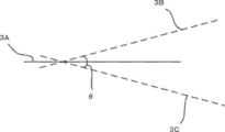
- a crystal grain having a crystal orientation within 15 ° from the ⁇ 001 ⁇ plane parallel to the surface of the metal plate means that one of the metal plates with respect to the ⁇ 001 ⁇ plane 3A as shown in FIG. Means a crystal grain having a crystal orientation in a range from a crystal orientation 3B inclined at an acute angle of 15 ° to the other surface side to a crystal orientation 3C inclined at an acute angle of 15 ° to the other surface side of the metal plate. That is, it means a crystal grain having a crystal orientation in the range of the angle ⁇ formed by the crystal orientation 3B and the crystal orientation 3C.
- the inventors further studied the structure of the metal plate to be formed based on the above findings. And the inventors investigated the relationship between the crystal orientation of the crystal grains in the plane strain tensile deformation field and the unequal biaxial tensile deformation field close to the plane strain deformation field, and the rough surface of the molded product. As a result, the inventors have found the following. In an equal biaxial tensile deformation field and an unequal biaxial tensile deformation field close to an equal biaxial tensile deformation field, strain concentrates on the ⁇ 001 ⁇ crystal grains 3 and preferentially deforms.
- the inventors considered the following.
- Surface deformation of a metal plate that occurs during processing if the ratio of crystal grains other than ⁇ 111 ⁇ crystal grains is within a predetermined range when performing processing that generates plane strain tensile deformation or plane strain tensile deformation and biaxial tensile deformation. It is possible to suppress the development of unevenness. That is, if the development of irregularities can be suppressed, rough skin that impairs the appearance of the molded product can be suppressed.
- the inventors also considered the following. ⁇ If the ratio of crystal grains other than ⁇ 111 ⁇ crystal grains is low and the size of the crystal grains other than ⁇ 111 ⁇ crystal grains is sufficiently small, even if the irregularities on the surface of the metal plate generated during processing develop, the metal The unevenness developed on the surface of the plate is not conspicuous, and is difficult to be recognized as rough skin that impairs the appearance of the molded product.
- the manufacturing method of the molded product of the second present disclosure completed based on the above knowledge has a bcc structure, and a metal plate that satisfies the following condition (A) or (B) on the surface of the metal plate: Plane strain tensile deformation, or plane strain tensile deformation and biaxial tensile deformation occur, and at least a part of the metal plate is subjected to a forming process in which the plate thickness reduction rate is 10% or more and 30% or less to manufacture a molded product.
- Manufacturing method of molded products (A) The area fraction of crystal grains other than crystal grains having a crystal orientation within 15 ° from the ⁇ 111 ⁇ plane parallel to the surface of the metal plate is 0.25 or more and 0.55 or less.
- (B) The area fraction of crystal grains other than crystal grains having a crystal orientation within 15 ° from the ⁇ 111 ⁇ plane parallel to the surface of the metal plate is 0.55 or less and the average crystal grain size is 15 ⁇ m or less. is there.
- plane strain tensile deformation, plane strain tensile deformation and biaxial tensile deformation occur on the metal plate having the bcc structure, and at least one of the metal plates is formed. Even when the part is subjected to a molding process in which the plate thickness reduction rate is 10% or more and 30% or less, the occurrence of rough skin is suppressed and a molded product excellent in design is obtained.
- a crystal grain having a crystal orientation within 15 ° from the ⁇ 111 ⁇ plane parallel to the surface of the metal plate means an acute angle of 15 ° on one surface side of the metal plate with respect to the ⁇ 111 ⁇ plane. It means a crystal grain having a crystal orientation in the range from the tilted crystal orientation to the crystal orientation tilted at an acute angle of 15 ° to the other surface side of the metal plate. That is, it means a crystal grain having a crystal orientation in the range of the angle ⁇ formed by these two crystal orientations.
- the metal plate is subjected to a forming process in which plane strain tensile deformation or plane strain tensile deformation and biaxial tensile deformation occur.
- this forming process there are deep drawing forming, stretch forming, drawing extending forming, and bending forming.
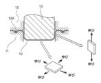
- a method of stretching and forming the metal plate 10 as shown in FIG. 7A can be mentioned.
- the edge of the metal plate 10 is sandwiched between the die 11 and the holder 12 on which the draw beads 12A are arranged. As a result, the draw bead 12A is bitten into the surface of the edge of the metal plate 10 and the metal plate 10 is fixed.
- FIG. 7B shows an example of a molded product obtained by the overhang forming process shown in FIG. 7A.
- a plane strain deformation occurs in the metal plate 10 (the portion that becomes the side surface of the molded product) located on the side surface side of the punch 10.
- the metal plate 10 located on the top surface of the punch 10 is subject to equibiaxial deformation or unequal biaxial tensile deformation that is relatively close to equibiaxial deformation.
- FIG. 8A shows an example of a molded product obtained by the drawing and drawing process shown in FIG. 8A.
- FIG. 8B shows an example of a molded product obtained by the drawing and drawing process shown in FIG. 8A.
- plane strain deformation occurs in the metal plate 10 (the portion that becomes the side surface of the molded product) located on the side surface side of the punch 10.
- the metal plate 10 located on the top surface of the punch 10 undergoes unequal biaxial tensile deformation that is relatively close to plane strain deformation.
- the plane strain tensile deformation is a deformation that extends in the ⁇ 1 direction and does not cause deformation in the ⁇ 2 direction.
- Biaxial tensile deformation is deformation that extends in the ⁇ 1 direction and also in the ⁇ 2 direction.
- the range of the strain ratio ⁇ is a theoretical value, for example, calculated from the maximum principal strain and the minimum principal strain measured from the shape change before and after forming the steel sheet (before and after deformation of the steel sheet) in the scribed circle transferred to the surface of the steel sheet.
- the range of the strain ratio ⁇ of each deformation is as follows. ⁇ Uniaxial tensile deformation: -0.5 ⁇ -0.1 ⁇ Plane strain tensile deformation: ⁇ 0.1 ⁇ ⁇ 0.1 Unequal biaxial deformation: 0.1 ⁇ ⁇ 0.8 ⁇ Equal biaxial deformation: 0.8 ⁇ ⁇ 1.0
- the metal plate is processed with a processing amount such that the plate thickness reduction rate is 10% to 30%. If the processing amount is less than 10%, the strain concentration on crystal grains other than ⁇ 111 ⁇ crystal grains (especially ⁇ 001 ⁇ crystal grains) is small, and unevenness tends to hardly develop during forming. Therefore, even if the metal plate does not satisfy the above conditions (a) and (b) or the above conditions (A) and (B), the rough surface of the molded product itself hardly occurs. On the other hand, if the plate thickness reduction rate exceeds 30%, the tendency of the metal plate (molded product) to break due to the forming process increases. Therefore, the processing amount of the forming process is set to the above range.
- Forming is performed with a processing amount such that at least a part of the metal plate has a plate thickness reduction rate of 10% to 30%.
- the forming process may be performed with a processing amount such that the entire metal plate excluding the edge (a portion sandwiched between the die and the holder) has a plate thickness reduction rate of 10% to 30%.
- the portion of the metal plate located on the top surface of the punch is 10% to 30% in thickness reduction rate.
- the metal plate is a metal plate having a bcc structure (body-centered cubic lattice structure).
- the metal plate having the bcc structure include metal plates such as ⁇ -Fe (, Li, Na, K, ⁇ -Ti, V, Cr, Ta, W. Among these, for producing a structure. From the viewpoint of being most easily available, steel plates (ferritic steel plates, bainite steel plates having a bainite single phase structure, martensite steel plates having a martensite single phase structure, etc.) are preferable, and ferritic steel plates are more preferable. Includes a steel plate (DP steel plate) in which martensite, bainite, and the like are present, in addition to a steel plate having a ferrite fraction of a metal structure of 100%.
- DP steel plate in which martensite, bainite, and the like are present, in addition to a steel plate having a ferrite fraction of a metal structure of 100%.
- the ferrite fraction of the metal structure of the ferritic steel sheet is preferably 50% or more, and more preferably 80% or more.
- the influence of the hard phase becomes strong.
- the hard phase becomes dominant, and the influence of the crystal orientation of ferrite (crystal grains other than ⁇ 111 ⁇ crystal grains (particularly ⁇ 001 ⁇ crystal grains)) is reduced. Therefore, there is a tendency that unevenness does not easily develop during the molding process, and it is difficult for the rough surface of the molded product to occur. Therefore, when a ferritic steel sheet having a ferrite fraction in the above range is applied, the effect of suppressing skin roughness becomes remarkable.
- the ferrite fraction can be measured by the following method. After the surface of the steel plate is polished, it is immersed in a nital solution to reveal a ferrite structure, and a structure photograph is taken with an optical microscope. Thereafter, the area of the ferrite structure relative to the entire area of the structure photograph is calculated.
- the thickness of the metal plate is not particularly limited, but is preferably 3 mm or less from the viewpoint of formability.
- crystal grains In the case of performing forming processing in which plane strain tensile deformation and biaxial tensile deformation occur, crystal grains ( ⁇ 001 ⁇ crystals having a crystal orientation within 15 ° from the ⁇ 001 ⁇ plane parallel to the surface of the metal plate on the surface of the metal plate. Grain) satisfies the following (a) or (b).
- the area fraction of ⁇ 001 ⁇ crystal grains is 0.20 or more and 0.35 or less.
- the ⁇ 001 ⁇ crystal grains have an area fraction of 0.45 or less and an average crystal grain size of 15 ⁇ m or less.
- ⁇ 001 ⁇ crystal grains are most vulnerable to stress of unequal biaxial tensile deformation close to equal biaxial tensile deformation and equal biaxial tensile deformation. Therefore, a metal that undergoes plane strain tensile deformation and biaxial tensile deformation, such as deep drawing and stretch forming, with a large amount of processing (a processing amount in which at least a part of the metal plate has a thickness reduction rate of 10% to 30%). If the forming process of the plate is carried out, the strain tends to concentrate on the ⁇ 001 ⁇ crystal grains, and the unevenness tends to develop on the ⁇ 001 ⁇ crystal grains.
- the metal plate satisfies the above (a)
- an appropriate concentration of strain due to the forming process is realized. Therefore, the development of unevenness is suppressed, and the occurrence of rough skin on the molded product is suppressed.
- the metal plate satisfies the above (b)
- an appropriate concentration of strain due to forming is realized when the area fraction of ⁇ 001 ⁇ crystal grains is in the range of 0.20 to 0.45. When the area fraction of the ⁇ 001 ⁇ crystal grains is less than 0.20, even if the unevenness develops, it becomes difficult to be recognized as rough skin of the molded product. Therefore, the occurrence of rough skin of the molded product is suppressed.
- the average crystal grain size of ⁇ 001 ⁇ crystal grains is 15 ⁇ m or less, but is preferably 10 ⁇ m or less from the viewpoint of suppressing rough skin.
- the average crystal grain size of ⁇ 001 ⁇ crystal grains is measured by the following method. Using the SEM, the surface of the metal plate is observed and the measurement area is arbitrarily selected. Using the EBSD method, ⁇ 001 ⁇ crystal grains are selected in each measurement region. Two test lines are drawn for each selected ⁇ 001 ⁇ grain. By calculating the arithmetic average of the two test lines, the average crystal grain size of ⁇ 001 ⁇ crystal grains is determined. Specifically, it is as follows.
- FIG. 10 is a schematic diagram illustrating a method of obtaining the average crystal grain size from the analysis result by the EBSD method. Referring to FIG. 10, test line 5 passing through the center of gravity of each ⁇ 001 ⁇ crystal grain 3 is drawn so that all ⁇ 001 ⁇ crystal grains 3 have the same orientation.
- a test line 6 passing through the center of gravity of each ⁇ 001 ⁇ crystal grain 3 is drawn so as to be orthogonal to the test line 5.
- the arithmetic average of the lengths of the two test lines 5 and 6 is defined as the crystal grain size of the crystal grains.
- the arithmetic average of the crystal grain sizes of all ⁇ 001 ⁇ crystal grains 3 in an arbitrary measurement region is defined as the average crystal grain size.
- the area fraction of ⁇ 001 ⁇ crystal grains is measured by the following method. Using SEM, observe the cross section (cut surface along the plate thickness direction) of the metal plate, and include any region (linear region) corresponding to the surface of the metal plate (surface facing the plate thickness direction) Select the measurement area. ⁇ 001 ⁇ crystal grain 3 is selected using the EBSD method. In each field of view, the area fraction of ⁇ 001 ⁇ crystal grains 3 is obtained by calculating the area fraction of ⁇ 001 ⁇ crystal grains 3 in the region corresponding to the surface of the metal plate (the surface facing the plate thickness direction). . Then, the average of the area fraction of ⁇ 001 ⁇ crystal grains 3 in an arbitrary measurement region is defined as the area fraction of ⁇ 001 ⁇ crystal grains.
- the area of the ⁇ 001 ⁇ crystal grains 3 with respect to a region (linear region) corresponding to the surface of the metal plate in contact with the plating layer or the like Measure the fraction.
- Crystal grains other than ⁇ 111 ⁇ grains In the case of performing forming processing that causes plane strain tensile deformation or plane strain tensile deformation and biaxial tensile deformation, the surface of the metal plate has a crystal orientation within 15 ° from the ⁇ 111 ⁇ plane parallel to the surface of the metal plate. Crystal grains other than crystal grains ( ⁇ 111 ⁇ crystal grains) (that is, crystal grains having a crystal orientation exceeding 15 ° from the ⁇ 111 ⁇ plane parallel to the surface of the metal plate) are the following (A) or (B Is satisfied. (A) The area fraction of crystal grains other than ⁇ 111 ⁇ crystal grains is 0.25 or more and 0.55 or less. (B) The area fraction of crystal grains other than ⁇ 111 ⁇ crystal grains is 0.55 or less and the average crystal grain size is 15 ⁇ m or less.
- crystal grains other than ⁇ 111 ⁇ crystal grains are weak against stress of plane strain tensile deformation and unequal biaxial tensile deformation close to plane strain deformation (that is, ⁇ 111 ⁇ crystal grains Is the strongest).
- processing amount at which at least a part of the metal plate has a plate thickness reduction rate of 10% to 30% in addition to deep drawing and stretch forming, bending forming, plane strain tensile deformation, or If the metal plate forming process in which plane strain tensile deformation and biaxial tensile deformation occur, strain is likely to concentrate on crystal grains other than ⁇ 111 ⁇ crystal grains, and irregularities are formed on crystal grains other than ⁇ 111 ⁇ crystal grains. Is easy to develop. And when there are many ratios of crystal grains other than ⁇ 111 ⁇ crystal grains, distortion tends to concentrate and an unevenness
- the metal plate satisfies the above (A)
- an appropriate concentration of strain by the forming process is realized. Therefore, the development of unevenness is suppressed, and the occurrence of rough skin on the molded product is suppressed.
- the metal plate satisfies the above (B)
- moderate strain concentration by forming is realized when the area fraction of crystal grains other than ⁇ 111 ⁇ crystal grains is in the range of 0.25 to 0.55. Is done. When the area fraction of crystal grains other than ⁇ 111 ⁇ crystal grains is less than 0.25, even if unevenness develops, it becomes difficult to be recognized as rough skin of the molded product. Therefore, the occurrence of rough skin of the molded product is suppressed.
- the average crystal grain size of the crystal grains other than ⁇ 111 ⁇ crystal grains is 15 ⁇ m or less, but is preferably 10 ⁇ m or less from the viewpoint of suppressing rough skin.
- the average crystal grain size of the crystal grains other than ⁇ 111 ⁇ crystal grains is preferably as small as possible from the viewpoint of suppressing rough skin, but is preferably 1 ⁇ m or more. This is because, since the orientation is controlled by recrystallization, it is difficult to achieve both ultrafine crystal grain size and orientation control.
- the average crystal grain size of crystal grains other than ⁇ 111 ⁇ crystal grains is measured by the same method as the average crystal grain size of ⁇ 001 ⁇ crystal grains, except that the crystal grains to be measured are different.
- the area fraction of crystal grains other than ⁇ 111 ⁇ crystal grains is measured by the same method as ⁇ 001 ⁇ crystal grains except that the crystal grains to be measured are different.
- the ferritic steel sheet suitable as the metal plate is, for example, mass%, C: 0.0060% or less, Si: 1.0% or less, Mn: 1.50% or less, P: 0.100% or less, S: 0.010% or less, Al: 0.00050 to 0.10%, N: 0.0040% or less, Ti: 0.0010 to 0.10%, Nb: 0.0010 to 0.10%, and B 0 to 0.0030%, the balance being Fe and impurities, and further having a chemical composition in which the value of F1 defined by the following formula (1) is 0.7 to 1.2 Is preferred.
- Carbon (C) is an impurity.
- C is known to reduce the ductility and deep drawability of the steel sheet. For this reason, the lower the C content, the better. Therefore, the C content is preferably 0.0060% or less.
- the lower limit of the C content can be appropriately set in consideration of the refining cost.
- the lower limit of the C content is, for example, 0.00050%.
- the upper limit with preferable C content is 0.0040%, More preferably, it is 0.0030%.
- Si 1.0% or less
- Silicon (Si) is an impurity. However, Si raises intensity
- the lower limit of the Si content is, for example, 0.005%.
- the lower limit of the Si content is, for example, 0.10%.
- the Si content is preferably 1.0% or less.
- the upper limit with preferable Si content is 0.5%. When the strength of the steel sheet is not required, the more preferable upper limit of the Si content is 0.05%.
- Mn 1.50% or less
- Manganese (Mn) is an impurity. However, Mn increases the strength of the steel sheet by solid solution strengthening. Furthermore, Mn fixes sulfur (S) as MnS. Therefore, the red hot embrittlement of the steel by FeS production
- the lower limit of the Mn content is, for example, 0.05%. On the other hand, when there is too much Mn content, the deep drawability and ductility of a steel plate will fall. Therefore, the Mn content is preferably 1.50% or less.
- the upper limit with preferable Mn content is 0.50%, More preferably, it is 0.20%.
- Phosphorus (P) is an impurity.
- P increases the strength while suppressing a decrease in the r value of the steel sheet by solid solution strengthening. Therefore, you may make it contain as needed.
- the lower limit of the P content can be appropriately set in consideration of the refining cost.
- the lower limit of the P content is, for example, 0.0010%.
- the P content is preferably 0.100% or less.
- the upper limit with preferable P content is 0.060%.
- S 0.010% or less Sulfur (S) is an impurity. S decreases the formability and ductility of the steel sheet. Therefore, the S content is preferably 0.010% or less. About the minimum of S content, it can set suitably in consideration of refining cost.
- the lower limit of the S content is, for example, 0.00030%.
- the upper limit with preferable S content is 0.006%, More preferably, it is 0.005%.
- the S content is preferably as low as possible.
- Al 0.00050-0.10%
- Aluminum (Al) deoxidizes molten steel.
- the Al content is preferably 0.00050% or more.
- the Al content is preferably 0.00050 to 0.10%.
- the upper limit with preferable Al content is 0.080%, More preferably, it is 0.060%.
- the minimum with preferable Al content is 0.005.
- Al content means content of what is called acid-soluble Al (sol.Al).
- N 0.0040% or less Nitrogen (N) is an impurity. N decreases the formability and ductility of the steel sheet. Therefore, the N content is preferably 0.0040% or less. About the minimum of N content, it can set suitably in consideration of refining cost. The lower limit of the N content is, for example, 0.00030%.
- Titanium (Ti) combines with C, N and S to form carbides, nitrides and sulfides. If Ti content is excessive with respect to C content, N content, and S content, solid solution C and solid solution N will reduce. In the case of general IF steel, Ti is preferably contained so that F1 defined by the following formula (1) is 0.7 or less. However, Ti remaining without being combined with C, N, and S is dissolved in the steel. If the solid solution Ti increases too much, the recrystallization temperature of the steel rises, so it is necessary to increase the annealing temperature. In this case, as will be described later, crystal grains other than ⁇ 111 ⁇ crystal grains (especially ⁇ 001 ⁇ crystal grains) are likely to grow after annealing.
- the upper limit of Ti content is preferably 0.10%.
- the upper limit with preferable Ti content is 0.08%, More preferably, it is 0.06%.
- Ti improves the formability and ductility by forming carbonitride.
- the lower limit of the Ti content is preferably 0.0010%.
- the minimum with preferable Ti content is 0.005%, More preferably, it is 0.01%.
- Niobium (Nb) combines with C, N, and S to form carbides, nitrides, and sulfides like Ti. If the Nb content is excessive with respect to the C content, the N content, and the S content, the solid solution C and the solid solution N are reduced. However, Nb remaining without being combined with C, N, and S is dissolved in the steel. If the solid solution Nb increases too much, it is necessary to increase the annealing temperature. In this case, crystal grains other than ⁇ 111 ⁇ crystal grains (especially ⁇ 001 ⁇ crystal grains) are likely to grow after annealing. Therefore, in order to lower the recrystallization temperature of steel, the upper limit of the Nb content is preferably 0.10%. The upper limit with preferable Nb content is 0.050%, More preferably, it is 0.030%.
- Nb improves formability and ductility by forming carbonitride. Furthermore, Nb suppresses recrystallization of austenite and refines the crystal grains of the hot rolled sheet.
- the lower limit of the Nb content is preferably 0.0010%.
- the minimum with preferable Nb content is 0.0012, More preferably, it is 0.0014%.
- B 0 to 0.0030% Boron (B) is an optional element.
- An ultra-low carbon steel sheet in which solute N and solute C are reduced generally has low grain boundary strength. For this reason, when performing a molding process in which plane strain deformation and biaxial tensile deformation occur, such as deep drawing molding and overhang molding, unevenness develops and roughening of the molded product is likely to occur. B improves the rough skin resistance by increasing the grain boundary strength. Therefore, you may contain B as needed. On the other hand, when the B content exceeds 0.0030%, the r value decreases. Therefore, the upper limit with preferable B content in the case of containing B is 0.0030%, More preferably, it is 0.0010%. In order to surely obtain the effect of increasing the grain boundary strength, the B content is preferably set to 0.0003% or more.
- the remainder consists of Fe and impurities.
- the impurities are those that are mixed from ore, scrap, or production environment as raw materials when industrially manufacturing steel materials, and are allowed within a range that does not adversely affect the steel plate. means.
- F1 defined by the formula (1) is more than 0.7 and 1.2 or less.
- Formula (1): F1 (C / 12 + N / 14 + S / 32) / (Ti / 48 + Nb / 93)
- the content (mass%) of each element in steel is substituted for each element symbol.
- F1 is a parameter formula that shows the relationship between C, N, and S, and Ti and Nb, which lowers the formability.
- the lower F1 the more Ti and Nb are contained. In this case, since Ti and Nb and C and N easily form carbonitrides, solid solution C and solid solution N can be reduced. Therefore, moldability is improved.
- F1 is too low, specifically, if F1 is 0.7 or less, Ti and Nb are contained in large excess. In this case, solute Ti and solute Nb increase. If the solute Ti and the solute Nb increase too much, the recrystallization temperature of the steel rises. Therefore, it is necessary to increase the annealing temperature.
- the lower limit of F1 is more than 0.7.
- F1 is 0.7 and 1.2 or less.
- the minimum with preferable F1 is 0.8, More preferably, it is 0.9.
- a preferable upper limit of the F1 value is 1.1.
- An example of the manufacturing method includes a surface strain imparting step, a heating step, a hot rolling step, a cooling step, a winding step, a cold rolling step, and an annealing step.
- the reduction ratio in the final two passes in the hot rolling process and the finishing temperature in the hot rolling process are important.
- the slab having the above chemical composition is subjected to a total reduction of 50% or more in the hot rolling process, and the finishing temperature is set to Ar 3 + 30 ° C. or more. Thereby, a ferritic steel sheet can be obtained.
- a ferritic steel sheet is manufactured.
- a slab having the above chemical composition is manufactured.
- strain is imparted to the surface layer of the slab before the hot rolling step or during rough rolling.
- the method for imparting strain include shot peening, cutting, and different peripheral speed rolling during rough rolling.
- the slab is heated.
- the heating is preferably set as appropriate so that the finishing temperature in the finish rolling in the hot rolling process (the surface temperature of the hot-rolled steel sheet after the final stand) is in the range of Ar 3 +30 to 50 ° C.
- the lower limit of the heating temperature is preferably 1000 ° C.
- the upper limit of the heating temperature is preferably 1280 ° C.
- the heating temperature is within the above range, the lower the heating temperature, the better the ductility and formability of the steel sheet. Therefore, a more preferable upper limit of the heating temperature is 1200 ° C.
- the hot rolling process includes rough rolling and finish rolling.
- rough rolling a slab is rolled to a certain thickness to produce a hot rolled steel sheet.
- the scale generated on the surface may be removed during rough rolling.
- the surface strain imparting step is performed during rough rolling to impart strain to the surface layer of the slab.
- the temperature during hot rolling is maintained so that the steel is in the austenite region. Strain is accumulated in the austenite crystal grains by hot rolling.
- the steel structure is transformed from austenite to ferrite by cooling after hot rolling. Since the temperature is in the austenite region during hot rolling, release of strain accumulated in the austenite crystal grains is suppressed.
- the austenite crystal grains in which the strain is accumulated are transformed into ferrite at a stroke by using the accumulated strain as a driving force at a stage where the strain is in a predetermined temperature range due to cooling after hot rolling. Thereby, a crystal grain can be refined
- the finishing temperature after hot rolling is Ar 3 + 30 ° C.
- the lower limit of the finishing temperature is Ar 3 + 30 ° C.
- the upper limit of the finishing temperature is preferably Ar 3 + 100 ° C.
- the finishing temperature is Ar 3 + 50 ° C. or lower, the strain can be stably accumulated in the austenite crystal grains, and the crystal grain diameter of crystal grains other than ⁇ 111 ⁇ crystal grains (particularly ⁇ 001 ⁇ crystal grains) Can be refined.
- the preferable upper limit of the finishing temperature is Ar 3 + 50 ° C.
- finish rolling a hot-rolled steel sheet having a certain thickness by rough rolling is further rolled.
- finish rolling continuous rolling by a plurality of passes is performed using a plurality of stands arranged in a row. If the amount of reduction in one pass is large, more strain is accumulated in the austenite crystal grains.
- the reduction ratio in the final two passes is 50% or more in total of the plate thickness reduction ratios. In this case, the crystal grains of the hot rolled steel sheet can be refined.
- the hot rolled steel sheet is cooled.
- the cooling conditions can be set as appropriate.
- the maximum cooling rate until the cooling is stopped is 100 ° C./s or more. In this case, the release of strain accumulated in the austenite crystal grains due to hot rolling is suppressed, and the crystal grains can be easily refined. The faster the cooling rate, the better.
- the time from completion of rolling to cooling to 680 ° C. is preferably 0.2 to 6.0 seconds. When the time from the completion of rolling to 680 ° C. is 6.0 seconds or less, the crystal grains after hot rolling can be easily refined. When the time from the completion of rolling to 680 ° C. is 2.0 seconds or less, the crystal grains after hot rolling can be further refined.
- ⁇ 111 ⁇ crystal grains are preferentially generated from the grain boundaries when the crystal grains are recrystallized. Therefore, it is easy to reduce crystal grains other than ⁇ 111 ⁇ crystal grains (particularly ⁇ 001 ⁇ crystal grains).
- the winding process is preferably performed at 400 to 690 ° C.
- the coiling temperature is 400 ° C. or higher, the precipitation of carbonitride is insufficient, and the solid solution C and solid solution N can be prevented from remaining. In this case, the formability of the cold rolled steel sheet is improved.
- the coiling temperature is 690 ° C. or less, the crystal grains can be prevented from coarsening during the slow cooling after the coiling. In this case, the formability of the cold rolled steel sheet is improved.
- Cold rolling is performed on the hot-rolled steel sheet after the winding process to produce a cold-rolled steel sheet.
- a higher rolling reduction in the cold rolling process is preferable.
- the ferritic steel sheet is an ultra-low carbon steel, ⁇ 111 ⁇ crystal grains tend to develop when the rolling reduction increases to some extent. Therefore, the r value after annealing tends to be high. Therefore, the rolling reduction in the cold rolling process is preferably 40% or more, more preferably 50% or more, and further preferably 60% or more.
- the practical upper limit of the rolling reduction in the cold rolling process is 95% because of the rolling equipment.
- the annealing method may be either continuous annealing or box annealing.
- the annealing temperature is preferably equal to or higher than the recrystallization temperature. In this case, recrystallization is promoted and the ductility and formability of the cold-rolled steel sheet are improved.
- the annealing temperature is preferably 830 ° C. or lower. If the annealing temperature is 830 ° C. or lower, the coarsening of crystal grains can be suppressed. In this case, the development of unevenness is suppressed during the molding process, and the occurrence of rough skin of the molded product is easily suppressed.
- the r value has heretofore been used as an index of press formability.
- the r value is higher as the surface of a steel sheet having a bcc structure has more ⁇ 111 ⁇ crystal grains and fewer ⁇ 001 ⁇ crystal grains.
- the higher the r value the better the moldability.
- an optimal annealing temperature has been selected to achieve a high r value.
- the r value cannot be used as an index for suppressing rough skin. This is because rough skin is likely to occur regardless of whether the r value is high or low. Further, even if the r value and the occurrence of rough skin are plotted, there is no correlation between them.
- crystal grains other than ⁇ 111 ⁇ crystal grains on the surface of the steel sheet are used as an index for suppressing rough skin.
- the area fraction of crystal grains (especially ⁇ 001 ⁇ crystal grains) other than ⁇ 111 ⁇ crystal grains on the surface of the steel sheet is determined by annealing temperature and processing heat treatment conditions before annealing (processing amount before hot rolling, hot rolling temperature). , Cold rolling rate, etc.). Specifically, a soaking temperature condition of 750 ° C. to 830 ° C. may be selected in the annealing process.
- the annealing temperature of the ferritic steel sheet is preferably lower than the annealing temperature of the prior art. This is because the lower the annealing temperature, the easier it is to suppress the coarsening of crystal grains. In order to set the annealing temperature low, it is necessary to lower the recrystallization temperature of the cold-rolled steel sheet. Therefore, as described above, it is preferable that the chemical composition of the ferritic steel sheet has a lower C content, Ti content, and Nb content as compared with the prior art. Thereby, even if the annealing temperature is 830 ° C. or less, recrystallization is promoted.
- a ferritic steel plate suitable as a metal plate can be produced.
- the rolling reduction is further increased to increase the shear band inside the steel sheet.
- crystal grains other than ⁇ 111 ⁇ crystal grains after annealing can be increased.
- the molded product of the first present disclosure is a metal plate molded product having a bcc structure and having a shape in which plane strain tensile deformation and biaxial tensile deformation are generated.
- the formula 10 ⁇ (D1 ⁇ D2) / D1 ⁇ 100 ⁇ 30
- the condition or the maximum hardness of the molded product is H1 and the minimum hardness of the molded product is H2
- the condition of the formula: 15 ⁇ (H1 ⁇ H2) / H1 ⁇ 100 ⁇ 40 is satisfied and the surface of the molded product is The following condition (c) or (d) is satisfied.
- the area fraction of crystal grains ( ⁇ 001 ⁇ crystal grains) having a crystal orientation within 15 ° from the ⁇ 001 ⁇ plane parallel to the surface of the molded product is 0.20 or more and 0.35 or less.
- the crystal grains having a crystal orientation within 15 ° from the ⁇ 001 ⁇ plane parallel to the surface of the molded product ( ⁇ 001 ⁇ crystal grains) have an area fraction of 0.45 or less and an average crystal grain size of 15 ⁇ m. It is as follows.
- the molded product of the second present disclosure is a molded product of a metal plate having a bcc structure and having a shape in which plane strain tensile deformation or plane strain tensile deformation and biaxial tensile deformation occur.
- the molded product of the second present disclosure has a formula: 10 ⁇ (D1 ⁇ D2) / D1 ⁇ 100 ⁇ 30, where D1 is the maximum thickness of the molded product and D2 is the minimum thickness of the molded product.
- condition or the maximum hardness of the molded product is H1 and the minimum hardness of the molded product is H2, the condition of the formula: 15 ⁇ (H1 ⁇ H2) / H1 ⁇ 100 ⁇ 40 is satisfied and the surface of the molded product is The following condition (C) or (D) is satisfied.
- C) The area fraction of crystal grains other than crystal grains ( ⁇ 111 ⁇ crystal grains) having a crystal orientation within 15 ° from the ⁇ 111 ⁇ plane parallel to the surface of the molded product is 0.25 or more and 0.55 or less. is there.
- D The area fraction of crystal grains other than crystal grains ( ⁇ 111 ⁇ crystal grains) having a crystal orientation within 15 ° from the ⁇ 111 ⁇ plane parallel to the surface of the molded product, and an average crystal The particle size is 15 ⁇ m or less.
- the metal plate which has a bcc structure is synonymous with the metal plate used with the manufacturing method of the molded article of the 1st and 2nd this indication.
- the molded product of the metal plate is subjected to a forming process that causes a plane strain tensile deformation or a plane strain tensile deformation and a biaxial tensile deformation.
- the method for confirming that the molded product is subjected to a plane strain tensile deformation, or a molding process that causes a plane strain tensile deformation and a biaxial tensile deformation is as follows.
- the three-dimensional shape of the molded product is measured, a mesh for numerical analysis is produced, and the process from the plate material to the three-dimensional shape is derived by computer inverse analysis. Then, a ratio (the ⁇ ) between the maximum principal strain and the minimum principal strain in each mesh is calculated. By this calculation, it can be confirmed that a plane strain tensile deformation, or a forming process that causes a plane strain tensile deformation and a biaxial tensile deformation is performed.
- the three-dimensional shape of the molded product is measured by a three-dimensional measuring machine such as Comet L3D (Tokyo Trading Techno System Co., Ltd.). Based on the obtained measurement data, mesh shape data of the molded product is obtained.
- satisfying the condition of the formula: 10 ⁇ (D1 ⁇ D2) / D1 ⁇ 100 ⁇ 30 means that the molded product is molded by a molding process in which at least a part of the metal plate has a plate thickness reduction rate of 10% to 30%. Can be considered. That is, the maximum plate thickness D1 of the molded product can be regarded as the plate thickness of the metal plate before the molding process, and the minimum plate thickness D2 of the molded product is the metal plate (molding) having the largest thickness reduction rate after the molding process. Product).
- the molded product is molded by a molding process in which at least a part of the metal plate has a plate thickness reduction rate of 10% to 30%. Can be considered. This is because work hardening (that is, work hardness: Vickers hardness) increases as the processing amount (thickness reduction) of the forming process increases (see FIG. 11).
- the portion having the maximum hardness H1 of the molded product can be regarded as the hardness of the metal plate (molded product) at the portion where the plate thickness reduction rate is the largest after the molding process, and the minimum hardness H2 of the molded product is It can be regarded as the hardness of the metal plate.
- the hardness is measured according to the Vickers hardness measurement method described in the JIS standard (JIS Z 2244). However, the measurement of hardness is not limited to this method, and a method of measuring hardness by another method and converting it to Vickers hardness using a hardness conversion table may be employed.
- the area fraction and the average crystal grain size of ⁇ 001 ⁇ crystal grains on the surface of the molded product, and the area fraction and the average crystal grain size of crystal grains other than ⁇ 111 ⁇ crystal grains on the surface of the molded product are measured at a site where the maximum plate thickness D1 or the minimum hardness H2 of the molded product is obtained.
- the conditions shown by said (c) or (d) are the conditions shown by said (a) or (b) demonstrated by the manufacturing method of the molded article of 1st this indication, and the metal plate before a shaping
- the conditions indicated by the above (C) or (D) are the same as the conditions indicated by the above (A) or (B) described in the method for producing a molded article of the second present disclosure, and the metal before the forming process. It is synonymous except that instead of the plate, the area fraction of crystal grains other than ⁇ 111 ⁇ crystal grains and the average crystal grain size on the surface of the molded product are used as conditions.
- the molded product according to the first and second disclosures of the present disclosure is regarded as a molded product molded by the manufacturing method of the molded product according to the first and second disclosures by satisfying the above requirements.
- the molded product of the first and second present disclosures is a molded product of a metal plate having a bcc structure and having a shape in which a plane strain tensile deformation or a plane strain tensile deformation and a biaxial tensile deformation occur.
- the cold rolling process was implemented with the rolling reduction shown in Table 2, and it was set as the cold rolled steel plate of the board thickness shown in Table 2.
- Each obtained cold-rolled steel sheet was annealed at the temperature shown in Table 2. In this way, steel plates 1 to 8 were obtained.
- the ferrite fractions of steel plates 1 to 8 were all 100%.
- the obtained steel sheet is then subjected to an overhanging process, and as shown in FIG. 12, the diameter R of the top plate portion 20A of the molded product 20 is 150 mm, the height H of the molded product 20 is 18 mm, and the molding is performed.
- No. 20 of the vertical wall portion 20B of the product 20 is a dish-shaped molded product No. 1 to 5 and 8 were molded.
- the molded product No. In the same manner as in 1 to 5 and 8, the molded product No. 6 to 7 and 9 were molded.
- decrease rate (The plate
- FIG. 17 shows the relationship between the result of visual evaluation and the average crystal grain size and crystal grain size of ⁇ 001 ⁇ crystal grains for the molded product obtained in the example.
- FIG. 13 is a schematic view of a steel plate observed from above. Referring to FIG. 13, three measurement areas 4 each having a 1 mm square were selected arbitrarily in the center portion from 1 ⁇ 4 in the width direction of the steel plate. In each measurement region 4, a crystal grain ( ⁇ 001 ⁇ crystal grain 3) having a crystal orientation within 15 ° from a ⁇ 001 ⁇ plane parallel to the steel sheet surface on the surface of the steel sheet was selected.
- the average crystal grain size of ⁇ 001 ⁇ crystal grains 3 was calculated. The measurement was performed on all ⁇ 001 ⁇ crystal grains 3 in three measurement regions 4. The arithmetic average of the crystal grain sizes of the ⁇ 001 ⁇ crystal grains 3 obtained was defined as the average crystal grain size. In addition, the average crystal grain size of ⁇ 001 ⁇ crystal grains 3 on the surface of the molded product is the same value as the average crystal grain size of ⁇ 001 ⁇ crystal grains 3 of the steel plate.
- a measurement test of the area fraction of ⁇ 001 ⁇ crystal grains was performed on the steel sheet. As described above, the measurement region 4 was selected from the steel sheet, and ⁇ 001 ⁇ crystal grains 3 were selected using the EBSD method. In each field of view, the area fraction of ⁇ 001 ⁇ crystal grains 3 was calculated, and the average value was obtained. Note that the area fraction of ⁇ 001 ⁇ crystal grains 3 of the formed product is the same value as the area fraction of ⁇ 001 ⁇ crystal grains 3 of the steel plate.
- a thickness thickness measurement test was performed on the molded product. Specifically, a molding simulation by a computer of a molded product was performed, and a portion where the plate thickness was maximum and minimum was specified. Thereafter, the thickness of the molded product was measured by using a thickness gauge at each of the portions where the thickness was maximum and minimum. Thus, the maximum plate thickness D1 and the minimum plate thickness D2 were obtained. However, the maximum plate thickness D1 determined the maximum plate thickness of the molded product (the entire molded product), and the minimum plate thickness D2 calculated the minimum plate thickness of the evaluation part of the molded product.
- Electrodeposition coating is performed after chemical conversion treatment, but as a simple evaluation method, the surface of the molded product is uniformly coated with lacquer spray, then visually observed, and according to the following criteria, the degree of occurrence of rough skin and the evaluation surface The sharpness was examined. Furthermore, as another parameter indicating the superiority or inferiority of the surface property, the value of arithmetic mean waviness Wa was measured with a laser microscope manufactured by Keyence. The measurement conditions were an evaluation length of 1.25 mm and a cutoff wavelength ⁇ c of 0.25 mm. Then, the profile on the longer wavelength side than the cutoff wavelength ⁇ c was evaluated.
- the evaluation criteria are as follows.
- a pattern is not visually confirmed on the evaluation portion surface of the top plate portion of the molded product, and the surface is glossy (Wa ⁇ 0.5 ⁇ m). It is more desirable as an automobile outer plate part, and it can be used as an outer plate part of a luxury car.
- C A pattern is visually confirmed on the evaluation portion surface of the top plate portion of the molded product, but the surface is glossy (1.0 ⁇ m ⁇ Wa ⁇ 1.5 ⁇ m). It cannot be used as a car outer plate part.
- FIGS. 14 to 16 Schematic diagrams showing the cross-sectional microstructure of 1 and surface irregularities are shown in FIGS. 14 to 16 are schematic views obtained by analyzing the cross section of the molded product by the EBSD method. 14 to 16, ND indicates the plate thickness direction, and TD indicates the plate width direction. From the comparison of FIGS. 14 to 16, the molded product No. corresponding to the comparative example. Compared with the molded product No. 1 corresponding to the example. Nos.
- decrease rate (The plate
- the thickness reduction rate of the evaluation part B of the top plate 20A of the molded product 20 (the central portion between the center and the edge of the top plate 20A) is the molded product No. Except for adjusting the height H of the molded product 20 to be the same as the plate thickness reduction rate of 101 to 109, 128 (in FIG. 12, the plate thickness reduction rate of the evaluation portion A of the top plate portion plate 20A), Molded product No. In the same manner as in 101 to 109 and 128, the molded product No. 110-118 and 129 were molded.
- the plate thickness reduction rate of the evaluation part C (the edge of the top plate 20A) of the top plate 20A of the molded product 20 is the molded product No. Except for adjusting the height H of the molded product 20 to be the same as the plate thickness reduction rate of 101 to 109, 128 (in FIG. 12, the plate thickness reduction rate of the evaluation portion A of the top plate portion plate 20A), Molded product No. In the same manner as in 101 to 109 and 128, the molded product No. 119 to 127 and 130 were molded.
- the scribed circle is transferred to the surface of the steel plate corresponding to the evaluation part of the molded product, and the shape change of the scribed circle before and after molding (before and after deformation) is measured, Maximum principal strain and minimum principal strain were measured. From these values, the deformation ratio ⁇ in the evaluation part of the molded product was calculated.
- Schematic diagrams showing the cross-sectional microstructure and surface irregularities of 101 are shown in FIGS. 18 to 20 are schematic diagrams obtained by analyzing the cross section of the molded product by the EBSD method.
- ND indicates the plate thickness direction
- TD indicates the plate width direction.
- ND indicates the plate thickness direction
- TD indicates the plate width direction.
- the molded product No. Compared to 101 the molded product No. It can be seen that Nos. 102 and 103 have low unevenness on the surface of the molded product, and the rough surface is suppressed and the design is excellent.
- the molded product No. No. 103 has a high unevenness on the surface of the molded product, but it can be seen that rough skin is suppressed and the design is excellent.
Landscapes
- Chemical & Material Sciences (AREA)
- Engineering & Computer Science (AREA)
- Mechanical Engineering (AREA)
- Materials Engineering (AREA)
- Metallurgy (AREA)
- Organic Chemistry (AREA)
- Physics & Mathematics (AREA)
- Thermal Sciences (AREA)
- Crystallography & Structural Chemistry (AREA)
- Shaping Metal By Deep-Drawing, Or The Like (AREA)
- Heat Treatment Of Sheet Steel (AREA)
- Straightening Metal Sheet-Like Bodies (AREA)
Priority Applications (10)
| Application Number | Priority Date | Filing Date | Title |
|---|---|---|---|
| EP16872881.4A EP3388538B1 (en) | 2015-12-11 | 2016-11-30 | Method of producing molded product and molded product |
| CN201680070927.XA CN108368562B (zh) | 2015-12-11 | 2016-11-30 | 成形品的制造方法及成形品 |
| BR112018011440-5A BR112018011440A2 (pt) | 2015-12-11 | 2016-11-30 | método de produção de produto moldado e produto moldado |
| CA3006845A CA3006845C (en) | 2015-12-11 | 2016-11-30 | Method of producing molded product and molded product |
| KR1020187016118A KR101940968B1 (ko) | 2015-12-11 | 2016-11-30 | 성형품의 제조 방법, 및 성형품 |
| MX2018006851A MX2018006851A (es) | 2015-12-11 | 2016-11-30 | Metodo de produccion de producto moldeado y producto moldeado. |
| JP2017518283A JP6156613B1 (ja) | 2015-12-11 | 2016-11-30 | 成形品の製造方法、及び成形品 |
| US15/781,891 US10603706B2 (en) | 2015-12-11 | 2016-11-30 | Method of producing molded product and molded product |
| RU2018124604A RU2678350C1 (ru) | 2015-12-11 | 2016-11-30 | Способ производства формованного продукта и формованный продукт |
| US16/795,796 US11161163B2 (en) | 2015-12-11 | 2020-02-20 | Method of producing molded product and molded product |
Applications Claiming Priority (4)
| Application Number | Priority Date | Filing Date | Title |
|---|---|---|---|
| JP2015242460 | 2015-12-11 | ||
| JP2015-242460 | 2015-12-11 | ||
| JP2016180635 | 2016-09-15 | ||
| JP2016-180635 | 2016-09-15 |
Related Child Applications (2)
| Application Number | Title | Priority Date | Filing Date |
|---|---|---|---|
| US15/781,891 A-371-Of-International US10603706B2 (en) | 2015-12-11 | 2016-11-30 | Method of producing molded product and molded product |
| US16/795,796 Division US11161163B2 (en) | 2015-12-11 | 2020-02-20 | Method of producing molded product and molded product |
Publications (1)
| Publication Number | Publication Date |
|---|---|
| WO2017098983A1 true WO2017098983A1 (ja) | 2017-06-15 |
Family
ID=59014131
Family Applications (1)
| Application Number | Title | Priority Date | Filing Date |
|---|---|---|---|
| PCT/JP2016/085633 WO2017098983A1 (ja) | 2015-12-11 | 2016-11-30 | 成形品の製造方法、及び成形品 |
Country Status (10)
| Country | Link |
|---|---|
| US (2) | US10603706B2 (zh) |
| EP (1) | EP3388538B1 (zh) |
| JP (1) | JP6156613B1 (zh) |
| KR (1) | KR101940968B1 (zh) |
| CN (1) | CN108368562B (zh) |
| BR (1) | BR112018011440A2 (zh) |
| CA (1) | CA3006845C (zh) |
| MX (1) | MX2018006851A (zh) |
| RU (1) | RU2678350C1 (zh) |
| WO (1) | WO2017098983A1 (zh) |
Cited By (3)
| Publication number | Priority date | Publication date | Assignee | Title |
|---|---|---|---|---|
| JP2019072861A (ja) * | 2017-10-12 | 2019-05-16 | 新日鐵住金株式会社 | 金属板、管状成形品、およびプレス成形品 |
| WO2019194201A1 (ja) * | 2018-04-02 | 2019-10-10 | 日本製鉄株式会社 | 金属板、金属板の製造方法、金属板の成形品の製造方法および金属板の成形品 |
| JP2019177396A (ja) * | 2018-03-30 | 2019-10-17 | 日本製鉄株式会社 | 金属成形板、塗装金属成形板および成形方法 |
Families Citing this family (4)
| Publication number | Priority date | Publication date | Assignee | Title |
|---|---|---|---|---|
| WO2017098983A1 (ja) | 2015-12-11 | 2017-06-15 | 新日鐵住金株式会社 | 成形品の製造方法、及び成形品 |
| CN107671159B (zh) * | 2017-10-18 | 2020-02-18 | 大连理工大学 | 超声振动辅助脱模的限制性模压模具及晶粒细化方法 |
| JP7196396B2 (ja) | 2018-02-02 | 2022-12-27 | 日本製鉄株式会社 | フェライト系鋼成形板、絞り成形方法、および絞り成形金型 |
| KR102179167B1 (ko) * | 2018-11-13 | 2020-11-16 | 삼성전자주식회사 | 반도체 패키지 |
Citations (4)
| Publication number | Priority date | Publication date | Assignee | Title |
|---|---|---|---|---|
| JPH09263900A (ja) * | 1996-03-29 | 1997-10-07 | Kawasaki Steel Corp | 耐リジング性および加工性に優れたフェライト系ステンレス鋼板およびその製造方法 |
| JPH11117038A (ja) * | 1997-10-09 | 1999-04-27 | Kawasaki Steel Corp | 加工性と耐肌荒れ性および耐リジング性に優れた冷延鋼板 |
| JP2001316775A (ja) * | 1999-12-03 | 2001-11-16 | Kawasaki Steel Corp | 耐リジング性および成形性に優れたフェライト系ステンレス鋼板ならびにその製造方法 |
| JP2002275595A (ja) * | 2001-03-21 | 2002-09-25 | Nisshin Steel Co Ltd | 耐リジング性および深絞り性に優れたフェライト系ステンレス鋼板およびその製造方法 |
Family Cites Families (14)
| Publication number | Priority date | Publication date | Assignee | Title |
|---|---|---|---|---|
| JPS5683193A (en) | 1979-12-11 | 1981-07-07 | Matsushita Electric Ind Co Ltd | Image sensor |
| JP3598590B2 (ja) * | 1994-12-05 | 2004-12-08 | Jfeスチール株式会社 | 磁束密度が高くかつ鉄損の低い一方向性電磁鋼板 |
| JPH1150211A (ja) * | 1997-08-05 | 1999-02-23 | Kawasaki Steel Corp | 深絞り加工性に優れる厚物冷延鋼板およびその製造方法 |
| TW480288B (en) * | 1999-12-03 | 2002-03-21 | Kawasaki Steel Co | Ferritic stainless steel plate and method |
| KR20100058851A (ko) * | 2008-11-25 | 2010-06-04 | 주식회사 포스코 | 성형성 및 리징성이 개선된 페라이트계 스테인리스 강의 제조방법 |
| KR101433493B1 (ko) * | 2010-02-26 | 2014-08-22 | 내셔널 유니버서티 코포레이션 요코하마 내셔널 유니버서티 | 결정축 〈001〉의 방위가 제어된 체심 입방(bcc) 구조의 고용체인 금속 재료 및 그 제조 방법 |
| WO2012014926A1 (ja) * | 2010-07-28 | 2012-02-02 | 新日本製鐵株式会社 | 熱延鋼板、冷延鋼板、亜鉛めっき鋼板およびこれらの製造方法 |
| JP5683193B2 (ja) | 2010-09-30 | 2015-03-11 | 株式会社Uacj | 耐リジング性に優れた成形加工用アルミニウム合金圧延板およびその製造方法 |
| JP5397569B2 (ja) * | 2011-04-21 | 2014-01-22 | 新日鐵住金株式会社 | 均一伸びと穴拡げ性に優れた高強度冷延鋼板及びその製造方法 |
| JP5856002B2 (ja) * | 2011-05-12 | 2016-02-09 | Jfeスチール株式会社 | 衝突エネルギー吸収能に優れた自動車用衝突エネルギー吸収部材およびその製造方法 |
| WO2012161248A1 (ja) * | 2011-05-25 | 2012-11-29 | 新日鐵住金株式会社 | 熱延鋼板及びその製造方法 |
| JP6177551B2 (ja) | 2013-03-15 | 2017-08-09 | 株式会社神戸製鋼所 | 絞り加工性と加工後の表面硬さに優れる熱延鋼板 |
| US20150371999A1 (en) * | 2014-06-18 | 2015-12-24 | Kabushiki Kaisha Toshiba | Semiconductor device, semiconductor storage device and method of manufacturing the semiconductor device |
| WO2017098983A1 (ja) | 2015-12-11 | 2017-06-15 | 新日鐵住金株式会社 | 成形品の製造方法、及び成形品 |
-
2016
- 2016-11-30 WO PCT/JP2016/085633 patent/WO2017098983A1/ja active Application Filing
- 2016-11-30 CA CA3006845A patent/CA3006845C/en not_active Expired - Fee Related
- 2016-11-30 EP EP16872881.4A patent/EP3388538B1/en active Active
- 2016-11-30 US US15/781,891 patent/US10603706B2/en active Active
- 2016-11-30 RU RU2018124604A patent/RU2678350C1/ru not_active IP Right Cessation
- 2016-11-30 MX MX2018006851A patent/MX2018006851A/es unknown
- 2016-11-30 KR KR1020187016118A patent/KR101940968B1/ko active IP Right Grant
- 2016-11-30 BR BR112018011440-5A patent/BR112018011440A2/pt active Search and Examination
- 2016-11-30 JP JP2017518283A patent/JP6156613B1/ja active Active
- 2016-11-30 CN CN201680070927.XA patent/CN108368562B/zh active Active
-
2020
- 2020-02-20 US US16/795,796 patent/US11161163B2/en active Active
Patent Citations (4)
| Publication number | Priority date | Publication date | Assignee | Title |
|---|---|---|---|---|
| JPH09263900A (ja) * | 1996-03-29 | 1997-10-07 | Kawasaki Steel Corp | 耐リジング性および加工性に優れたフェライト系ステンレス鋼板およびその製造方法 |
| JPH11117038A (ja) * | 1997-10-09 | 1999-04-27 | Kawasaki Steel Corp | 加工性と耐肌荒れ性および耐リジング性に優れた冷延鋼板 |
| JP2001316775A (ja) * | 1999-12-03 | 2001-11-16 | Kawasaki Steel Corp | 耐リジング性および成形性に優れたフェライト系ステンレス鋼板ならびにその製造方法 |
| JP2002275595A (ja) * | 2001-03-21 | 2002-09-25 | Nisshin Steel Co Ltd | 耐リジング性および深絞り性に優れたフェライト系ステンレス鋼板およびその製造方法 |
Non-Patent Citations (1)
| Title |
|---|
| See also references of EP3388538A4 * |
Cited By (9)
| Publication number | Priority date | Publication date | Assignee | Title |
|---|---|---|---|---|
| JP2019072861A (ja) * | 2017-10-12 | 2019-05-16 | 新日鐵住金株式会社 | 金属板、管状成形品、およびプレス成形品 |
| JP2019177396A (ja) * | 2018-03-30 | 2019-10-17 | 日本製鉄株式会社 | 金属成形板、塗装金属成形板および成形方法 |
| WO2019194201A1 (ja) * | 2018-04-02 | 2019-10-10 | 日本製鉄株式会社 | 金属板、金属板の製造方法、金属板の成形品の製造方法および金属板の成形品 |
| JPWO2019194201A1 (ja) * | 2018-04-02 | 2020-04-30 | 日本製鉄株式会社 | 金属板、金属板の製造方法、金属板の成形品の製造方法および金属板の成形品 |
| KR20200124309A (ko) * | 2018-04-02 | 2020-11-02 | 닛폰세이테츠 가부시키가이샤 | 금속판, 금속판의 제조 방법, 금속판의 성형품의 제조 방법, 및 금속판의 성형품 |
| CN111936652A (zh) * | 2018-04-02 | 2020-11-13 | 日本制铁株式会社 | 金属板、金属板的制造方法、金属板的成型品的制造方法及金属板的成型品 |
| US11035022B2 (en) | 2018-04-02 | 2021-06-15 | Nippon Steel Corporation | Metal sheet, method of producing metal sheet, method of producing molded product of metal sheet, and molded product of metal sheet |
| CN111936652B (zh) * | 2018-04-02 | 2021-06-29 | 日本制铁株式会社 | 金属板、金属板的制造方法、金属板的成型品的制造方法及金属板的成型品 |
| KR102276818B1 (ko) * | 2018-04-02 | 2021-07-15 | 닛폰세이테츠 가부시키가이샤 | 금속판, 금속판의 제조 방법, 금속판의 성형품의 제조 방법, 및 금속판의 성형품 |
Also Published As
| Publication number | Publication date |
|---|---|
| US20200188981A1 (en) | 2020-06-18 |
| CN108368562A (zh) | 2018-08-03 |
| JP6156613B1 (ja) | 2017-07-05 |
| CA3006845A1 (en) | 2017-06-15 |
| CN108368562B (zh) | 2021-07-20 |
| MX2018006851A (es) | 2018-08-01 |
| US10603706B2 (en) | 2020-03-31 |
| JPWO2017098983A1 (ja) | 2017-12-07 |
| EP3388538A1 (en) | 2018-10-17 |
| RU2678350C1 (ru) | 2019-01-28 |
| US20180361456A1 (en) | 2018-12-20 |
| EP3388538A4 (en) | 2018-11-21 |
| US11161163B2 (en) | 2021-11-02 |
| BR112018011440A2 (pt) | 2018-11-27 |
| EP3388538B1 (en) | 2022-11-09 |
| KR101940968B1 (ko) | 2019-01-21 |
| KR20180069916A (ko) | 2018-06-25 |
| CA3006845C (en) | 2019-09-17 |
Similar Documents
| Publication | Publication Date | Title |
|---|---|---|
| JP6156613B1 (ja) | 成形品の製造方法、及び成形品 | |
| EP3495528A1 (en) | Steel sheet and plated steel sheet | |
| KR101987573B1 (ko) | 고강도 강판 및 그 제조 방법 | |
| JP6753542B2 (ja) | 金属板、金属板の製造方法、金属板の成形品の製造方法および金属板の成形品 | |
| JP6443126B2 (ja) | フェライト系薄鋼板 | |
| CN107109558B (zh) | 拉深罐用钢板及其制造方法 | |
| WO2020145256A1 (ja) | 鋼板及びその製造方法 | |
| JP2007291514A (ja) | 冷延−再結晶焼鈍後の面内異方性が小さい熱延鋼板、面内異方性が小さい冷延鋼板およびそれらの製造方法 | |
| JP5930144B1 (ja) | 絞り缶用鋼板及びその製造方法 | |
| KR102562003B1 (ko) | 강판 및 그 제조 방법 | |
| JP2010077513A (ja) | 冷延鋼板およびその製造方法 | |
| JP6809651B2 (ja) | 鋼板及びその製造方法 | |
| US20210381076A1 (en) | Thin steel sheet and method for manufacturing same | |
| CN109722508B (zh) | 铁素体系不锈钢板及其制造方法 | |
| JP6331511B2 (ja) | 冷延鋼板 |
Legal Events
| Date | Code | Title | Description |
|---|---|---|---|
| ENP | Entry into the national phase |
Ref document number: 2017518283 Country of ref document: JP Kind code of ref document: A |
|
| 121 | Ep: the epo has been informed by wipo that ep was designated in this application |
Ref document number: 16872881 Country of ref document: EP Kind code of ref document: A1 |
|
| ENP | Entry into the national phase |
Ref document number: 3006845 Country of ref document: CA |
|
| WWE | Wipo information: entry into national phase |
Ref document number: MX/A/2018/006851 Country of ref document: MX |
|
| ENP | Entry into the national phase |
Ref document number: 20187016118 Country of ref document: KR Kind code of ref document: A |
|
| NENP | Non-entry into the national phase |
Ref country code: DE |
|
| REG | Reference to national code |
Ref country code: BR Ref legal event code: B01A Ref document number: 112018011440 Country of ref document: BR |
|
| WWE | Wipo information: entry into national phase |
Ref document number: 2016872881 Country of ref document: EP |
|
| ENP | Entry into the national phase |
Ref document number: 2016872881 Country of ref document: EP Effective date: 20180711 |
|
| ENP | Entry into the national phase |
Ref document number: 112018011440 Country of ref document: BR Kind code of ref document: A2 Effective date: 20180606 |