EP3388538A1 - Molded product manufacturing method and molded product - Google Patents
Molded product manufacturing method and molded product Download PDFInfo
- Publication number
- EP3388538A1 EP3388538A1 EP16872881.4A EP16872881A EP3388538A1 EP 3388538 A1 EP3388538 A1 EP 3388538A1 EP 16872881 A EP16872881 A EP 16872881A EP 3388538 A1 EP3388538 A1 EP 3388538A1
- Authority
- EP
- European Patent Office
- Prior art keywords
- molded product
- crystal grains
- metal sheet
- sheet
- tensile deformation
- Prior art date
- Legal status (The legal status is an assumption and is not a legal conclusion. Google has not performed a legal analysis and makes no representation as to the accuracy of the status listed.)
- Granted
Links
- 238000004519 manufacturing process Methods 0.000 title description 2
- 239000013078 crystal Substances 0.000 claims abstract description 437
- 229910052751 metal Inorganic materials 0.000 claims abstract description 219
- 239000002184 metal Substances 0.000 claims abstract description 219
- 238000000465 moulding Methods 0.000 claims abstract description 113
- 230000007423 decrease Effects 0.000 claims abstract description 59
- 238000000034 method Methods 0.000 claims abstract description 56
- 229910000831 Steel Inorganic materials 0.000 claims description 116
- 239000010959 steel Substances 0.000 claims description 116
- 229910000859 α-Fe Inorganic materials 0.000 claims description 39
- 230000002159 abnormal effect Effects 0.000 description 59
- 230000015572 biosynthetic process Effects 0.000 description 53
- 238000012360 testing method Methods 0.000 description 38
- 230000000052 comparative effect Effects 0.000 description 33
- 238000011156 evaluation Methods 0.000 description 31
- 238000000137 annealing Methods 0.000 description 30
- 239000010936 titanium Substances 0.000 description 27
- 238000005259 measurement Methods 0.000 description 25
- 238000005098 hot rolling Methods 0.000 description 24
- 239000006104 solid solution Substances 0.000 description 24
- 238000003754 machining Methods 0.000 description 23
- 238000005096 rolling process Methods 0.000 description 23
- 239000010955 niobium Substances 0.000 description 22
- 238000013461 design Methods 0.000 description 18
- 238000001816 cooling Methods 0.000 description 16
- 238000001953 recrystallisation Methods 0.000 description 15
- 229910001566 austenite Inorganic materials 0.000 description 13
- 238000010438 heat treatment Methods 0.000 description 13
- 239000011572 manganese Substances 0.000 description 13
- 238000012545 processing Methods 0.000 description 13
- 239000000126 substance Substances 0.000 description 12
- 230000000007 visual effect Effects 0.000 description 12
- 238000004804 winding Methods 0.000 description 12
- 230000005764 inhibitory process Effects 0.000 description 11
- 238000004458 analytical method Methods 0.000 description 10
- 239000010960 cold rolled steel Substances 0.000 description 10
- 239000012535 impurity Substances 0.000 description 10
- 230000002401 inhibitory effect Effects 0.000 description 10
- 239000000203 mixture Substances 0.000 description 10
- 229910052799 carbon Inorganic materials 0.000 description 9
- 238000005097 cold rolling Methods 0.000 description 9
- 230000000694 effects Effects 0.000 description 8
- 229910052757 nitrogen Inorganic materials 0.000 description 8
- 230000009467 reduction Effects 0.000 description 8
- 229910052717 sulfur Inorganic materials 0.000 description 8
- 230000002265 prevention Effects 0.000 description 7
- 229910052719 titanium Inorganic materials 0.000 description 7
- 229910052758 niobium Inorganic materials 0.000 description 6
- 239000002344 surface layer Substances 0.000 description 5
- IJGRMHOSHXDMSA-UHFFFAOYSA-N Atomic nitrogen Chemical compound N#N IJGRMHOSHXDMSA-UHFFFAOYSA-N 0.000 description 4
- 230000006866 deterioration Effects 0.000 description 4
- 238000007542 hardness measurement Methods 0.000 description 4
- 238000007670 refining Methods 0.000 description 4
- NINIDFKCEFEMDL-UHFFFAOYSA-N Sulfur Chemical compound [S] NINIDFKCEFEMDL-UHFFFAOYSA-N 0.000 description 3
- 229910001563 bainite Inorganic materials 0.000 description 3
- 238000005452 bending Methods 0.000 description 3
- 238000004364 calculation method Methods 0.000 description 3
- 239000010410 layer Substances 0.000 description 3
- 229910000734 martensite Inorganic materials 0.000 description 3
- 239000000463 material Substances 0.000 description 3
- 238000004088 simulation Methods 0.000 description 3
- 239000002436 steel type Substances 0.000 description 3
- 238000005728 strengthening Methods 0.000 description 3
- 239000011593 sulfur Substances 0.000 description 3
- VCGRFBXVSFAGGA-UHFFFAOYSA-N (1,1-dioxo-1,4-thiazinan-4-yl)-[6-[[3-(4-fluorophenyl)-5-methyl-1,2-oxazol-4-yl]methoxy]pyridin-3-yl]methanone Chemical compound CC=1ON=C(C=2C=CC(F)=CC=2)C=1COC(N=C1)=CC=C1C(=O)N1CCS(=O)(=O)CC1 VCGRFBXVSFAGGA-UHFFFAOYSA-N 0.000 description 2
- ABDDQTDRAHXHOC-QMMMGPOBSA-N 1-[(7s)-5,7-dihydro-4h-thieno[2,3-c]pyran-7-yl]-n-methylmethanamine Chemical compound CNC[C@@H]1OCCC2=C1SC=C2 ABDDQTDRAHXHOC-QMMMGPOBSA-N 0.000 description 2
- HCDMJFOHIXMBOV-UHFFFAOYSA-N 3-(2,6-difluoro-3,5-dimethoxyphenyl)-1-ethyl-8-(morpholin-4-ylmethyl)-4,7-dihydropyrrolo[4,5]pyrido[1,2-d]pyrimidin-2-one Chemical compound C=1C2=C3N(CC)C(=O)N(C=4C(=C(OC)C=C(OC)C=4F)F)CC3=CN=C2NC=1CN1CCOCC1 HCDMJFOHIXMBOV-UHFFFAOYSA-N 0.000 description 2
- WNEODWDFDXWOLU-QHCPKHFHSA-N 3-[3-(hydroxymethyl)-4-[1-methyl-5-[[5-[(2s)-2-methyl-4-(oxetan-3-yl)piperazin-1-yl]pyridin-2-yl]amino]-6-oxopyridin-3-yl]pyridin-2-yl]-7,7-dimethyl-1,2,6,8-tetrahydrocyclopenta[3,4]pyrrolo[3,5-b]pyrazin-4-one Chemical compound C([C@@H](N(CC1)C=2C=NC(NC=3C(N(C)C=C(C=3)C=3C(=C(N4C(C5=CC=6CC(C)(C)CC=6N5CC4)=O)N=CC=3)CO)=O)=CC=2)C)N1C1COC1 WNEODWDFDXWOLU-QHCPKHFHSA-N 0.000 description 2
- KVCQTKNUUQOELD-UHFFFAOYSA-N 4-amino-n-[1-(3-chloro-2-fluoroanilino)-6-methylisoquinolin-5-yl]thieno[3,2-d]pyrimidine-7-carboxamide Chemical compound N=1C=CC2=C(NC(=O)C=3C4=NC=NC(N)=C4SC=3)C(C)=CC=C2C=1NC1=CC=CC(Cl)=C1F KVCQTKNUUQOELD-UHFFFAOYSA-N 0.000 description 2
- CYJRNFFLTBEQSQ-UHFFFAOYSA-N 8-(3-methyl-1-benzothiophen-5-yl)-N-(4-methylsulfonylpyridin-3-yl)quinoxalin-6-amine Chemical compound CS(=O)(=O)C1=C(C=NC=C1)NC=1C=C2N=CC=NC2=C(C=1)C=1C=CC2=C(C(=CS2)C)C=1 CYJRNFFLTBEQSQ-UHFFFAOYSA-N 0.000 description 2
- OKTJSMMVPCPJKN-UHFFFAOYSA-N Carbon Chemical compound [C] OKTJSMMVPCPJKN-UHFFFAOYSA-N 0.000 description 2
- AYCPARAPKDAOEN-LJQANCHMSA-N N-[(1S)-2-(dimethylamino)-1-phenylethyl]-6,6-dimethyl-3-[(2-methyl-4-thieno[3,2-d]pyrimidinyl)amino]-1,4-dihydropyrrolo[3,4-c]pyrazole-5-carboxamide Chemical compound C1([C@H](NC(=O)N2C(C=3NN=C(NC=4C=5SC=CC=5N=C(C)N=4)C=3C2)(C)C)CN(C)C)=CC=CC=C1 AYCPARAPKDAOEN-LJQANCHMSA-N 0.000 description 2
- UCKMPCXJQFINFW-UHFFFAOYSA-N Sulphide Chemical compound [S-2] UCKMPCXJQFINFW-UHFFFAOYSA-N 0.000 description 2
- 238000006243 chemical reaction Methods 0.000 description 2
- 238000005520 cutting process Methods 0.000 description 2
- 238000011161 development Methods 0.000 description 2
- 150000004767 nitrides Chemical class 0.000 description 2
- XGVXKJKTISMIOW-ZDUSSCGKSA-N simurosertib Chemical compound N1N=CC(C=2SC=3C(=O)NC(=NC=3C=2)[C@H]2N3CCC(CC3)C2)=C1C XGVXKJKTISMIOW-ZDUSSCGKSA-N 0.000 description 2
- 238000005482 strain hardening Methods 0.000 description 2
- 230000009466 transformation Effects 0.000 description 2
- AETVBWZVKDOWHH-UHFFFAOYSA-N 2-[4-[2-(2,3-dihydro-1H-inden-2-ylamino)pyrimidin-5-yl]-3-(1-ethylazetidin-3-yl)oxypyrazol-1-yl]-1-(2,4,6,7-tetrahydrotriazolo[4,5-c]pyridin-5-yl)ethanone Chemical compound C1C(CC2=CC=CC=C12)NC1=NC=C(C=N1)C=1C(=NN(C=1)CC(=O)N1CC2=C(CC1)NN=N2)OC1CN(C1)CC AETVBWZVKDOWHH-UHFFFAOYSA-N 0.000 description 1
- YJLUBHOZZTYQIP-UHFFFAOYSA-N 2-[5-[2-(2,3-dihydro-1H-inden-2-ylamino)pyrimidin-5-yl]-1,3,4-oxadiazol-2-yl]-1-(2,4,6,7-tetrahydrotriazolo[4,5-c]pyridin-5-yl)ethanone Chemical compound C1C(CC2=CC=CC=C12)NC1=NC=C(C=N1)C1=NN=C(O1)CC(=O)N1CC2=C(CC1)NN=N2 YJLUBHOZZTYQIP-UHFFFAOYSA-N 0.000 description 1
- YLZOPXRUQYQQID-UHFFFAOYSA-N 3-(2,4,6,7-tetrahydrotriazolo[4,5-c]pyridin-5-yl)-1-[4-[2-[[3-(trifluoromethoxy)phenyl]methylamino]pyrimidin-5-yl]piperazin-1-yl]propan-1-one Chemical compound N1N=NC=2CN(CCC=21)CCC(=O)N1CCN(CC1)C=1C=NC(=NC=1)NCC1=CC(=CC=C1)OC(F)(F)F YLZOPXRUQYQQID-UHFFFAOYSA-N 0.000 description 1
- 229910000838 Al alloy Inorganic materials 0.000 description 1
- ZOXJGFHDIHLPTG-UHFFFAOYSA-N Boron Chemical compound [B] ZOXJGFHDIHLPTG-UHFFFAOYSA-N 0.000 description 1
- 229910000975 Carbon steel Inorganic materials 0.000 description 1
- PWHULOQIROXLJO-UHFFFAOYSA-N Manganese Chemical compound [Mn] PWHULOQIROXLJO-UHFFFAOYSA-N 0.000 description 1
- OAICVXFJPJFONN-UHFFFAOYSA-N Phosphorus Chemical compound [P] OAICVXFJPJFONN-UHFFFAOYSA-N 0.000 description 1
- XUIMIQQOPSSXEZ-UHFFFAOYSA-N Silicon Chemical compound [Si] XUIMIQQOPSSXEZ-UHFFFAOYSA-N 0.000 description 1
- RTAQQCXQSZGOHL-UHFFFAOYSA-N Titanium Chemical compound [Ti] RTAQQCXQSZGOHL-UHFFFAOYSA-N 0.000 description 1
- 238000003483 aging Methods 0.000 description 1
- 229910052782 aluminium Inorganic materials 0.000 description 1
- XAGFODPZIPBFFR-UHFFFAOYSA-N aluminium Chemical compound [Al] XAGFODPZIPBFFR-UHFFFAOYSA-N 0.000 description 1
- 229910052796 boron Inorganic materials 0.000 description 1
- 239000010962 carbon steel Substances 0.000 description 1
- 230000008859 change Effects 0.000 description 1
- 229910052804 chromium Inorganic materials 0.000 description 1
- 239000011248 coating agent Substances 0.000 description 1
- 238000000576 coating method Methods 0.000 description 1
- 239000004035 construction material Substances 0.000 description 1
- 230000003247 decreasing effect Effects 0.000 description 1
- 230000006735 deficit Effects 0.000 description 1
- 238000004070 electrodeposition Methods 0.000 description 1
- 230000001771 impaired effect Effects 0.000 description 1
- 238000009776 industrial production Methods 0.000 description 1
- 229910052742 iron Inorganic materials 0.000 description 1
- 239000004922 lacquer Substances 0.000 description 1
- 239000007788 liquid Substances 0.000 description 1
- 229910052748 manganese Inorganic materials 0.000 description 1
- 238000012986 modification Methods 0.000 description 1
- 230000004048 modification Effects 0.000 description 1
- GUCVJGMIXFAOAE-UHFFFAOYSA-N niobium atom Chemical compound [Nb] GUCVJGMIXFAOAE-UHFFFAOYSA-N 0.000 description 1
- 230000003287 optical effect Effects 0.000 description 1
- 229910052698 phosphorus Inorganic materials 0.000 description 1
- 239000011574 phosphorus Substances 0.000 description 1
- 238000001556 precipitation Methods 0.000 description 1
- 230000008569 process Effects 0.000 description 1
- 238000005480 shot peening Methods 0.000 description 1
- 229910052710 silicon Inorganic materials 0.000 description 1
- 239000010703 silicon Substances 0.000 description 1
- 238000010583 slow cooling Methods 0.000 description 1
- 238000002791 soaking Methods 0.000 description 1
- 239000000243 solution Substances 0.000 description 1
- 239000007921 spray Substances 0.000 description 1
- 239000007858 starting material Substances 0.000 description 1
- 229910052715 tantalum Inorganic materials 0.000 description 1
- 229910052721 tungsten Inorganic materials 0.000 description 1
- 229910052720 vanadium Inorganic materials 0.000 description 1
Images


Classifications
-
- B—PERFORMING OPERATIONS; TRANSPORTING
- B21—MECHANICAL METAL-WORKING WITHOUT ESSENTIALLY REMOVING MATERIAL; PUNCHING METAL
- B21D—WORKING OR PROCESSING OF SHEET METAL OR METAL TUBES, RODS OR PROFILES WITHOUT ESSENTIALLY REMOVING MATERIAL; PUNCHING METAL
- B21D22/00—Shaping without cutting, by stamping, spinning, or deep-drawing
- B21D22/20—Deep-drawing
-
- C—CHEMISTRY; METALLURGY
- C21—METALLURGY OF IRON
- C21D—MODIFYING THE PHYSICAL STRUCTURE OF FERROUS METALS; GENERAL DEVICES FOR HEAT TREATMENT OF FERROUS OR NON-FERROUS METALS OR ALLOYS; MAKING METAL MALLEABLE, e.g. BY DECARBURISATION OR TEMPERING
- C21D8/00—Modifying the physical properties by deformation combined with, or followed by, heat treatment
- C21D8/02—Modifying the physical properties by deformation combined with, or followed by, heat treatment during manufacturing of plates or strips
- C21D8/04—Modifying the physical properties by deformation combined with, or followed by, heat treatment during manufacturing of plates or strips to produce plates or strips for deep-drawing
- C21D8/0405—Modifying the physical properties by deformation combined with, or followed by, heat treatment during manufacturing of plates or strips to produce plates or strips for deep-drawing of ferrous alloys
-
- C—CHEMISTRY; METALLURGY
- C21—METALLURGY OF IRON
- C21D—MODIFYING THE PHYSICAL STRUCTURE OF FERROUS METALS; GENERAL DEVICES FOR HEAT TREATMENT OF FERROUS OR NON-FERROUS METALS OR ALLOYS; MAKING METAL MALLEABLE, e.g. BY DECARBURISATION OR TEMPERING
- C21D9/00—Heat treatment, e.g. annealing, hardening, quenching or tempering, adapted for particular articles; Furnaces therefor
- C21D9/46—Heat treatment, e.g. annealing, hardening, quenching or tempering, adapted for particular articles; Furnaces therefor for sheet metals
- C21D9/48—Heat treatment, e.g. annealing, hardening, quenching or tempering, adapted for particular articles; Furnaces therefor for sheet metals deep-drawing sheets
-
- C—CHEMISTRY; METALLURGY
- C22—METALLURGY; FERROUS OR NON-FERROUS ALLOYS; TREATMENT OF ALLOYS OR NON-FERROUS METALS
- C22C—ALLOYS
- C22C38/00—Ferrous alloys, e.g. steel alloys
- C22C38/001—Ferrous alloys, e.g. steel alloys containing N
-
- C—CHEMISTRY; METALLURGY
- C22—METALLURGY; FERROUS OR NON-FERROUS ALLOYS; TREATMENT OF ALLOYS OR NON-FERROUS METALS
- C22C—ALLOYS
- C22C38/00—Ferrous alloys, e.g. steel alloys
- C22C38/002—Ferrous alloys, e.g. steel alloys containing In, Mg, or other elements not provided for in one single group C22C38/001 - C22C38/60
-
- C—CHEMISTRY; METALLURGY
- C22—METALLURGY; FERROUS OR NON-FERROUS ALLOYS; TREATMENT OF ALLOYS OR NON-FERROUS METALS
- C22C—ALLOYS
- C22C38/00—Ferrous alloys, e.g. steel alloys
- C22C38/02—Ferrous alloys, e.g. steel alloys containing silicon
-
- C—CHEMISTRY; METALLURGY
- C22—METALLURGY; FERROUS OR NON-FERROUS ALLOYS; TREATMENT OF ALLOYS OR NON-FERROUS METALS
- C22C—ALLOYS
- C22C38/00—Ferrous alloys, e.g. steel alloys
- C22C38/04—Ferrous alloys, e.g. steel alloys containing manganese
-
- C—CHEMISTRY; METALLURGY
- C22—METALLURGY; FERROUS OR NON-FERROUS ALLOYS; TREATMENT OF ALLOYS OR NON-FERROUS METALS
- C22C—ALLOYS
- C22C38/00—Ferrous alloys, e.g. steel alloys
- C22C38/06—Ferrous alloys, e.g. steel alloys containing aluminium
-
- C—CHEMISTRY; METALLURGY
- C22—METALLURGY; FERROUS OR NON-FERROUS ALLOYS; TREATMENT OF ALLOYS OR NON-FERROUS METALS
- C22C—ALLOYS
- C22C38/00—Ferrous alloys, e.g. steel alloys
- C22C38/12—Ferrous alloys, e.g. steel alloys containing tungsten, tantalum, molybdenum, vanadium, or niobium
-
- C—CHEMISTRY; METALLURGY
- C22—METALLURGY; FERROUS OR NON-FERROUS ALLOYS; TREATMENT OF ALLOYS OR NON-FERROUS METALS
- C22C—ALLOYS
- C22C38/00—Ferrous alloys, e.g. steel alloys
- C22C38/14—Ferrous alloys, e.g. steel alloys containing titanium or zirconium
-
- C—CHEMISTRY; METALLURGY
- C21—METALLURGY OF IRON
- C21D—MODIFYING THE PHYSICAL STRUCTURE OF FERROUS METALS; GENERAL DEVICES FOR HEAT TREATMENT OF FERROUS OR NON-FERROUS METALS OR ALLOYS; MAKING METAL MALLEABLE, e.g. BY DECARBURISATION OR TEMPERING
- C21D2211/00—Microstructure comprising significant phases
- C21D2211/005—Ferrite
-
- C—CHEMISTRY; METALLURGY
- C21—METALLURGY OF IRON
- C21D—MODIFYING THE PHYSICAL STRUCTURE OF FERROUS METALS; GENERAL DEVICES FOR HEAT TREATMENT OF FERROUS OR NON-FERROUS METALS OR ALLOYS; MAKING METAL MALLEABLE, e.g. BY DECARBURISATION OR TEMPERING
- C21D8/00—Modifying the physical properties by deformation combined with, or followed by, heat treatment
- C21D8/02—Modifying the physical properties by deformation combined with, or followed by, heat treatment during manufacturing of plates or strips
- C21D8/0221—Modifying the physical properties by deformation combined with, or followed by, heat treatment during manufacturing of plates or strips characterised by the working steps
- C21D8/0236—Cold rolling
-
- C—CHEMISTRY; METALLURGY
- C22—METALLURGY; FERROUS OR NON-FERROUS ALLOYS; TREATMENT OF ALLOYS OR NON-FERROUS METALS
- C22C—ALLOYS
- C22C38/00—Ferrous alloys, e.g. steel alloys
-
- Y—GENERAL TAGGING OF NEW TECHNOLOGICAL DEVELOPMENTS; GENERAL TAGGING OF CROSS-SECTIONAL TECHNOLOGIES SPANNING OVER SEVERAL SECTIONS OF THE IPC; TECHNICAL SUBJECTS COVERED BY FORMER USPC CROSS-REFERENCE ART COLLECTIONS [XRACs] AND DIGESTS
- Y10—TECHNICAL SUBJECTS COVERED BY FORMER USPC
- Y10T—TECHNICAL SUBJECTS COVERED BY FORMER US CLASSIFICATION
- Y10T428/00—Stock material or miscellaneous articles
- Y10T428/12—All metal or with adjacent metals
- Y10T428/12389—All metal or with adjacent metals having variation in thickness
Landscapes
- Chemical & Material Sciences (AREA)
- Engineering & Computer Science (AREA)
- Mechanical Engineering (AREA)
- Materials Engineering (AREA)
- Metallurgy (AREA)
- Organic Chemistry (AREA)
- Physics & Mathematics (AREA)
- Thermal Sciences (AREA)
- Crystallography & Structural Chemistry (AREA)
- Shaping Metal By Deep-Drawing, Or The Like (AREA)
- Heat Treatment Of Sheet Steel (AREA)
- Straightening Metal Sheet-Like Bodies (AREA)
Abstract
Description
- The present disclosure relates to a method of producing a molded product and a molded product.
- In recent years, in the fields of automobiles, aircraft, marine vessels, construction materials, home electric appliances, and the like, design is becoming more prioritized in order to respond to users' needs. This tends to make especially the shapes of exterior parts complicated. In order to mold a metal sheet into a molded product having a complicated shape, it is necessary to generate strain in a metal sheet. However, as the machining amount increases, fine protrusions and recesses are likely to be formed on the surface of a molded product, resulting in abnormal grain growth. This is problematic because excellent exterior appearance may be impaired.
- For example,
Patent Document 1 discloses that protrusions and recesses form a stripe pattern (ridging) in parallel to the rolling direction. Specifically,Patent Document 1 discloses the following. It is possible to obtain a rolled sheet of an aluminum alloy for molding, which has excellent ridging resistance by controlling an average Taylor factor determined when regarding that molding causes plane strain deformation in the rolling width direction that is the main strain direction. An average Taylor factor that is calculated based on all crystal orientations present in crystal texture is strongly related to ridging resistance. Ridging resistance can be stably improved with certainty by controlling crystal texture such that the average Taylor factor value satisfies specific conditions. - Patent Document 1: Japanese Patent No.
5683193 - However,
Patent Document 1 merely discloses that ridging can be inhibited upon molding of a metal sheet in which uniaxial tensile deformation occurs in the rolling width direction as the main strain direction. In addition, molding such as deep drawing molding or overhang molding of a metal sheet, which may cause plane strain tensile deformation and biaxial tensile deformation, is not considered. - Meanwhile, in recent years, there is a demand to produce a molded product having a complicated shape even in the case of molding such as deep drawing molding or overhang molding, which may cause plane strain tensile deformation and biaxial tensile deformation of a metal sheet. However, in fact, when molding is conducted for a metal sheet at a large machining amount (a machining amount corresponding to a sheet thickness decrease rate of 10% or more for a metal sheet), protrusions and recesses are formed on the surface of a molded product, which results in abnormal grain growth and impairment of excellent appearance. Similar problems are seen under current circumstances also in the case of molding of a metal sheet in which plane strain tensile deformation exclusively occurs.
- For the above reasons, for example, conventional automobile exterior sheet products are produced at machining amounts within a limited scope in which the amount of distortion of a product face corresponds to a sheet thickness decrease rate of less than 10% for a metal sheet. In other words, processing conditions are limited in order to avoid the occurrence of abnormal grain growth. However, there is a demand for further complicated shapes of automobile exterior sheet products. A method that achieves a sheet thickness decrease rate of 10% or more for a metal sheet and inhibition of abnormal grain growth in a well-balanced manner upon molding has been awaited
- In consideration of the above, an object of one aspect of the disclosure is to provide a method of producing a molded product, by which a molded product that is excellent in design because of prevention of the occurrence of abnormal grain growth can be obtained even by treating a metal sheet having a bcc structure, and by molding the metal sheet to cause plane strain tensile deformation and/or biaxial tensile deformation and allowing at least a part of the metal sheet to have a sheet thickness decrease rate of from 10% to 30%.
- In addition, an object of another aspect of the disclosure is to provide a molded product that is excellent in design because of prevention of the occurrence of abnormal grain growth, even when the molded product is a molded product of a metal sheet including a bcc structure, in which a shape of the molded product results from plane strain tensile deformation, or plane strain tensile deformation and biaxial tensile deformation, and a maximum sheet thickness and a minimum sheet thickness of the molded product are represented by D1 and D2, respectively, a
formula 10≤(D1-D2)/D1×100≤30 is satisfied, or a maximum hardness and a minimum hardness of the molded product are represented by H1 and H2, respectively, aformula 15≤(H1-H2)/H1×100≤40 is satisfied. - The inventors examined surface texture for molding of a metal sheet at a large machining amount (a machining amount corresponding to a sheet thickness decrease rate of 10% or more for a metal sheet) in order to produce a molded product having a complicated shape of a recent trend. As a result, the inventors obtained the following findings. When plane strain tensile deformation and biaxial tensile deformation occurs, crystal grains having a crystal orientation of 15° or less relative to a (001) plane parallel to the surface of a metal sheet having a bcc structure are deformed in a prioritized manner, and thus, protrusions and recesses are formed. Therefore, the present inventors focused on the area fraction and average crystal grain size of crystal grains having a crystal orientation of 15° or less relative to a (001) plane parallel to the surface of a metal sheet. As a result, the inventors found that it is possible to obtain a molded product that is excellent in design by controlling the area fraction and average crystal grain size of such crystal grains so as to inhibit the formation of protrusions and recesses, thereby inhibiting the occurrence of abnormal grain growth.
- The inventors further obtained the following findings. When plane strain tensile deformation, or plane strain tensile deformation and biaxial tensile deformation occurs, crystal grains other than crystal grains having a crystal orientation of 15° or less relative to a (111) plane parallel to the surface of a metal sheet having a bcc structure are deformed in a prioritized manner, and thus, protrusions and recesses are formed. Therefore, the present inventors focused on the area fraction of crystal grains other than crystal grains having a crystal orientation of 15° or less relative to a (111) plane parallel to the surface of a metal sheet. As a result, the inventors found that it is possible to obtain a molded product that is excellent in design by controlling the area fraction of such crystal grains so as to inhibit the formation of protrusions and recesses, thereby inhibiting the occurrence of abnormal grain growth.
- The disclosure is summarized as follows.
-
- <1> A method of producing a molded product, including:
- treating a metal sheet having a bcc structure and a surface that satisfies either of the following conditions (a) or (b); and
- molding the metal sheet to cause plane strain tensile deformation and biaxial tensile deformation and allowing at least a part of the metal sheet to have a sheet thickness decrease rate of from 10% to 30%:
- (a) an area fraction of crystal grains having a crystal orientation of 15° or less relative to a (001) plane parallel to the surface of the metal sheet is from 0.20 to 0.35;
- (b) the area fraction of crystal grains having a crystal orientation of 15° or less relative to a (001) plane parallel to the surface of the metal sheet is 0.45 or less, and an average crystal grain size thereof is 15 µm or less.
- <2> A method of producing a molded product, including:
- treating a metal sheet having a bcc structure and a surface that satisfies either of the following conditions (A) or (B); and
- molding the metal sheet to cause plane strain tensile deformation, or plane strain tensile deformation and biaxial tensile deformation and allowing at least a part of the metal sheet to have a sheet thickness decrease rate of from 10% to 30%:
- (A) an area fraction of crystal grains other than crystal grains having a crystal orientation of 15° or less relative to a (111) plane parallel to the surface of the metal sheet is from 0.25 to 0.55;
- (B) the area fraction of crystal grains other than crystal grains having a crystal orientation of 15° or less relative to a (111) plane parallel to the surface of the metal sheet is 0.55 or less, and an average crystal grain size thereof is 15 µm or less.
- <3> The method of producing a molded product according to <1> or <2>, wherein the metal sheet is a steel sheet.
- <4> The method of producing a molded product according to any one of <1> to <3>, wherein the metal sheet is a ferrite-based steel sheet having a metallic-structure ferrite fraction of 50% or more.
- <5> A molded product of a metal sheet including a bcc structure, wherein:
- a shape of the molded product results from plane strain tensile deformation and biaxial tensile deformation;
- a maximum sheet thickness and a minimum sheet thickness of the molded product are represented by D1 and D2, respectively, a
formula 10≤(D1-D2)/D1×100≤30 is satisfied; and - a surface of the molded product satisfies either of the following conditions (c) or (d):
- (c) an area fraction of crystal grains having a crystal orientation of 15° or less relative to a (001) plane parallel to the surface of the molded product is from 0.20 to 0.35;
- (d) the area fraction of crystal grains having a crystal orientation of 15° or less relative to a (001) plane parallel to the surface of the molded product is 0.45 or less, and an average crystal grain size thereof is 15 µm or less.
- <6> A molded product of a metal sheet including a bcc structure, wherein:
- a shape of the molded product results from plane strain tensile deformation, or plane strain tensile deformation and biaxial tensile deformation;
- a maximum sheet thickness and a minimum sheet thickness of the molded product are represented by D1 and D2, respectively, a
formula 10≤(D1-D2)/D1×100≤30 is satisfied; and - a surface of the molded product satisfies either of the following conditions (C) or (D):
- (C) an area fraction of crystal grains other than crystal grains having a crystal orientation of 15° or less relative to a (111) plane parallel to the surface of the molded product is from 0.25 to 0.55;
- (D) the area fraction of crystal grains other than crystal grains having a crystal orientation of 15° or less relative to a (111) plane parallel to the surface of the molded product is 0.55 or less, and an average crystal grain size thereof is 15 µm or less.
- <7> The molded product according to <5> or <6>, wherein the metal sheet is a steel sheet.
- <8> The molded product according to any one of <5> to <7>, wherein the metal sheet is a ferrite-based steel sheet having a metallic-structure ferrite fraction of 50% or more.
- <9> A molded product of a metal sheet including a bcc structure, wherein:
- a shape of the molded product results from plane strain tensile deformation and biaxial tensile deformation;
- a maximum hardness and a minimum hardness of the molded product are represented by H1 and H2, respectively, a
formula 15≤(H1-H2)/H1×100≤40 is satisfied; and - a surface of the molded product satisfies either of the following conditions (c) or (d):
- (c) an area fraction of crystal grains having a crystal orientation of 15° or less relative to a (001) plane parallel to the surface of the molded product is from 0.20 to 0.35;
- (d) the area fraction of crystal grains having a crystal orientation of 15° or less relative to a (001) plane parallel to the surface of the molded product is 0.45 or less, and an average crystal grain size thereof is 15 µm or less.
- <10> A molded product of a metal sheet including a bcc structure, wherein:
- a shape of the molded product results from plane strain tensile deformation, or plane strain tensile deformation and biaxial tensile deformation;
- a maximum hardness and a minimum hardness of the molded product are represented by H1 and H2, respectively, a
formula 15≤(H1-H2)/H1×100≤40 is satisfied; and - a surface of the molded product satisfies either of the following conditions (C) or (D):
- (C) an area fraction of crystal grains other than crystal grains having a crystal orientation of 15° or less relative to a (111) plane parallel to the surface of the molded product is from 0.25 to 0.55;
- (D) the area fraction of crystal grains other than crystal grains having a crystal orientation of 15° or less relative to a (111) plane parallel to the surface of the molded product is 0.55 or less, and an average crystal grain size thereof is 15 µm or less.
- <11> The molded product according to <9> or <10>, wherein the metal sheet is a steel sheet.
- <12> The molded product according to any one of <9> to <11>, wherein the metal sheet is a steel sheet having a metallic-structure ferrite fraction of 50% or more.
- According to one aspect of the disclosure, it is possible to provide a method of producing a molded product, by which a molded product that is excellent in design because of prevention of the occurrence of abnormal grain growth can be obtained even by treating a metal sheet having a bcc structure, and by molding the metal sheet to cause plane strain tensile deformation, or plane strain tensile deformation and biaxial tensile deformation and allowing at least a part of the metal sheet to have a sheet thickness decrease rate of from 10% to 30%.
- According to another aspect of the disclosure, it is possible to provide a molded product that is excellent in design because of prevention of the occurrence of abnormal grain growth, even when the molded product is a molded product of a metal sheet including a bcc structure, in which a shape of the molded product results from plane strain tensile deformation, or plane strain tensile deformation and biaxial tensile deformation, in which given that the maximum sheet thickness and the minimum sheet thickness of the molded product are represented by D1 and D2, respectively, a
formula 10≤(D1-D2)/D1×100≤30 is satisfied, or given that the maximum hardness and the minimum hardness of the molded product are represented by H1 and H2, respectively, and aformula 15≤(H1-H2)/H1×100≤30 is satisfied. -
-
Figure 1 is an SEM observation image of the surface of a metal sheet examined by a Bulge forming test. -
Figure 2 is an SEM observation image of the surface of a metal sheet after further conducting electropolishing following a Bulge forming test. -
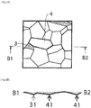
Figure 3A schematically illustrates analysis of the surface of a metal sheet in which formation of protrusions and recesses is less obvious after a Bulge forming test by the EBSD method. -
Figure 3B schematically illustrates protrusions and recesses on the surface of a metal sheet in an A1-A2 cross-section ofFigure 3A . -
Figure 4A schematically illustrates analysis of the surface of a metal sheet in which formation of protrusions and recesses is more obvious after a Bulge forming test by the EBSD method. -
Figure 4B schematically illustrates protrusions and recesses on the surface of a metal sheet in a B1-B2 cross-section ofFigure 4A . -
Figure 5A schematically illustrates analysis of the surface of a metal sheet in which formation of protrusions and recesses is more obvious after a Bulge forming test by the EBSD method. -
Figure 5B schematically illustrates protrusions and recesses on the surface of a metal sheet in a C1-C2 cross-section ofFigure 5A . -
Figure 6 schematically explains the definition of the expression "crystal grains having a crystal orientation of 15° or less relative to a (001) plane parallel to a surface of the metal sheet." -
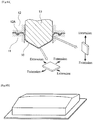
Figure 7A schematically illustrates one example of overhang molding. -
Figure 7B schematically illustrates one example of a molded product obtained by overhang molding illustrated inFigure 7A . -
Figure 8A schematically illustrates one example of drawing overhang molding. -
Figure 8B schematically illustrates one example of a molded product obtained by drawing overhang molding illustrated inFigure 8A . -
Figure 9 schematically explains plane strain tensile deformation, biaxial tensile deformation, and uniaxial tensile deformation. -
Figure 10 schematically illustrates a method of calculating the average crystal grain size of (001) crystal grains based on analysis results of the EBSD method. -
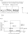
Figure 11 is a graph indicating a relationship between the sheet thickness decrease rate and work hardness for molding. -
Figure 12 schematically explains the molded product produced in the Examples. -
Figure 13 schematically illustrates an observational view of a steel sheet from the top. -
Figure 14 schematically illustrates cross-sectional micro-texture of a molded product No. 2 of the corresponding Example and surface protrusions and recesses thereof. -
Figure 15 schematically illustrates cross-sectional micro-texture of a molded product No. 3 of the corresponding Example and surface protrusions and recesses thereof. -
Figure 16 schematically illustrates cross-sectional micro-texture of a molded product No. 1 of the corresponding Comparative Example and surface protrusions and recesses thereof. -
Figure 17 illustrates visual observation evaluation results and a relationship between the average crystal grain size and crystal grain sizes of (001) crystal grains for the molded product obtained in the first Example. -
Figure 18 schematically illustrates cross-sectional micro-texture of a molded product No. 102 of the corresponding Example and surface protrusions and recesses thereof. -
Figure 19 schematically illustrates cross-sectional micro-texture of a molded product No. 103 of the corresponding Example and surface protrusions and recesses thereof. -
Figure 20 schematically illustrates cross-sectional micro-texture of a molded product No. 101 of the corresponding Comparative Example and surface protrusions and recesses thereof. - Hereinafter, some aspects of the disclosure are described in detail with reference to the drawings. Identical reference numerals are given to the same or corresponding portions and the description thereof will not be repeated in the drawings.
- The inventors made various studies on the metallic structure of metal sheets to be treated by molding. As a result, the following findings were obtained.
- (1) In a metal sheet having a bcc structure, the (001) plane is more susceptible to stress due to equi-biaxial tensile deformation and non-equi-biaxial tensile deformation similar to equi-biaxial tensile deformation than the (111) plane.
In addition, the (101) plane is more susceptible to stress due to equi-biaxial tensile deformation and non-equi-biaxial tensile deformation similar to equi-biaxial tensile deformation than the (111) plane. Therefore, in a case in which molding of a metal sheet such as deep drawing molding or overhang molding, which causes plane strain tensile deformation and biaxial tensile deformation, is conducted at a large machining amount (a machining amount that results in a sheet thickness decrease rate of from 10% to 30% for at least a part of the metal sheet), strain is concentrated in crystal grains having a crystal orientation of 15° relative to a (001) plane parallel to the surface of a metal sheet. - (2) Strain concentrated in crystal grains having a crystal orientation of 15° relative to a (001) plane parallel to the surface of a metal sheet causes development of the surface of the metal sheet, which results in deterioration of surface texture (i.e., the occurrence of abnormal grain growth).
- (3) When protrusions and recesses developed on the surface of a metal sheet are connected, it further accelerates deterioration of surface texture (i.e., the occurrence of obvious abnormal grain growth).
- (4) Even in a case in which there are excessively few crystal grains having a crystal orientation of 15° relative to a (001) plane parallel to the surface of a metal sheet, localized deformation occurs in a distributed manner in crystal grains having a crystal orientation of about 15° relative to a (001) plane parallel to the surface of a metal sheet (e.g., crystal grains having a crystal orientation of from more than 15° to 30° relative to a (001) plane).
This causes the development of protrusions and recesses on the surface of a metal sheet. -
Figure 1 is a scanning electron microscope (SEM) observation image of the surface of a metal sheet examined by the Bulge forming test.Figure 2 is an SEM observation image of the surface of a metal sheet after further conducting electropolishing following a Bulge forming test. In bothFigures 1 and 2 , the observational point is an apex of a metal sheet that is bulging to form a mountain shape as a result of the Bulge forming test. When a metal sheet was examined by the Bulge forming test with reference toFigures 1 and 2 , recesses 1 and 2 having sizes of from about 10 to 20 µm were observed. - In other words, overhang molding of a metal sheet causes stress to be concentrated at a certain point of the metal sheet. At the site where stress has been concentrated, protrusions and recesses are formed on the surface of the metal sheet. In addition, the formed protrusions and recesses are connected, thereby further developing protrusions and recesses to be formed. Thus, protrusions and recesses cause abnormal grain growth to occur.
-
Figures 3A to 5A each schematically illustrate analysis of the surface of a metal sheet examined by the Bulge forming test by the electron back scattering diffraction (EBSD) method.Figure 3A schematically illustrates a metal sheet, on the surface of which obvious formation of protrusions and recesses has not occurred in a case in which the overhang height is set to 40 mm for Bulge forming (corresponding to molding which allows at least a part of a metal sheet to have a sheet thickness decrease rate of 25%).Figures 4A and5A each schematically illustrate a metal sheet, on the surface of which obvious formation of protrusions and recesses has occurred in a case in which the overhang height is set to 40 mm for Bulge forming (corresponding to molding which allows at least a part of a metal sheet to have a sheet thickness decrease rate of 25%). -
Figures 3B to 5B schematically illustrate protrusions and recesses of the surface of a metal sheet in the cross-section in each ofFigures 3A to 5A .
In other words,Figure 3B schematically illustrates a cross-section of protrusions and recesses on the surface of a metal sheet, on which obvious formation of protrusions and recesses has not occurred.Figures 4B and5B each schematically illustrate a metal sheet, on the surface of which obvious formation of protrusions and recesses has occurred. - Among crystal grains in
Figures 3A to 5A , each darkgray crystal grain 3 is a crystal grain having a crystal orientation of 15° or less relative to a (001) plane parallel to a surface of a metal sheet. Such crystal grain is hereinafter also referred to as a "(001) crystal grain." Among crystal grains inFigures 3A to 5A , each palegray crystal grain 4 is a crystal grain having a crystal orientation of about 15° relative to a (001) plane parallel to a surface of a metal sheet (e.g., a crystal grain having a crystal orientation of from more than 15° to 20° relative to the (001) plane). Such crystal grain is hereinafter also referred to as a "(001) adjacent crystal grain." Anumerical reference 31 denotes a surface of a metal sheet on which (001)crystal grains 3 exist inFigures 3B to 5B . In addition, anumerical reference 41 denotes a surface of a metal sheet on which (001)adjacent crystal grains 4 exist. - It was found that the area fraction of (001)
crystal grains 3 is from 0.20 to 0.35 on a surface of a metal sheet, on which obvious formation of protrusions and recesses has not occurred, with reference toFigures 3A and 3B . - It was found that the area fraction of (001)
crystal grains 3 is less than 0.20 or more than 0.35 on a surface of a metal sheet, on which obvious formation of protrusions and recesses has occurred, with reference toFigures 4A and5A andFigures 4B andFigure 5B - This is because strain is concentrated in (001)
crystal grains 3 upon overhang molding. Strain concentrated in (001)crystal grains 3 causes formation of protrusions and recesses on the surface of a metal sheet. Further, when the area fraction of (001)crystal grains 3 is high, the probability that (001)crystal grains 3 are in contact with each other increases, which facilitates the formed protrusions and recesses to be connected with each other. Meanwhile, when the area fraction of (001)crystal grains 3 is excessively low, localized deformation of (001)adjacent crystal grains 4 occurs in a distributed manner, which allows protrusions and recesses to form on a surface of a metal sheet. - Specifically, in a case in which the area fraction of (001)
crystal grains 3 is in an appropriate range, localized deformation of (001)adjacent crystal grains 4 does not occur in a distributed manner on a surface of a metal sheet. This results in localized deformation of (001)crystal grains 3 alone. Accordingly, deep recesses are formed in a region where (001)crystal grains 3 exist while formation of flat portions is ensured in a region where other crystal grains (e.g., (001) adjacent crystal grains 4) exist (seeFigure 3B ). This indicates that even in a case in which high protrusions and deep recesses are formed, formation of flat portions can be ensured as long as deep and fine recesses are formed. - Meanwhile, in a case in which the area fraction of (001)
crystal grains 3 is excessively low, localized deformation of (001)adjacent crystal grains 4 occurs in a distributed manner on a surface of a metal sheet. This causes localized deformation of (001)adjacent crystal grains 4 as well as (001)crystal grains 3. Accordingly, a region where shallow recesses are formed is enlarged, which results in relatively fewer flat portions (seeFigure 4B ). - In addition, in a case in which the area fraction of (001)
crystal grains 3 is excessively high, localized deformation of (001)crystal grains 3 occurs on a surface of a metal sheet, and a region where shallow recesses are formed is enlarged, which results in fewer flat portions (Figure 5B ). - This means that either an excessively high or low area fraction of (001)
crystal grains 3 causes formation of protrusions and recesses on a surface of a steel sheet and facilitates the formed protrusions and recesses to be connected to each other, and such connection causes further formation of protrusions and recesses. - The inventors therefore considered that in a case in which molding that causes plane strain tensile deformation and biaxial tensile deformation is conducted, it is possible to inhibit formation of protrusions and recesses on a surface of a metal sheet by setting the proportion of (001)
crystal grains 3 within a given range. In other words, it is possible to inhibit abnormal grain growth that impairs the excellent appearance of a molded product by inhibiting formation of protrusions and recesses. - Meanwhile, the inventors considered that in a case in which the proportion of (001)
crystal grains 3 is low, even when formation of protrusions and recesses on the surface of a metal sheet occurs during processing, protrusions and recesses formed on a surface of a metal sheet are less obvious, and thus, the formation is unlikely to be recognized as abnormal grain growth that impairs the excellent appearance of a molded product, provided that sizes of (001)crystal grains 3 are sufficiently small. - The first method of producing a molded product of the disclosure, which has been completed based on the above findings, is a method of producing a molded product, which includes treating a metal sheet having a bcc structure and a surface that satisfies either of the following conditions (a) or (b), and molding the metal sheet to cause plane strain tensile deformation and biaxial tensile deformation and allowing at least a part of the metal sheet to have a sheet thickness decrease rate of from 10% to 30%:
- (a) the area fraction of crystal grains having a crystal orientation of 15° or less relative to a (001) plane parallel to a surface of the metal sheet is from 0.20 to 0.35;
- (b) the area fraction of crystal grains having a crystal orientation of 15° or less relative to a (001) plane parallel to a surface of the metal sheet is 0.45 or less, and the average crystal grain size thereof is 15 µm or less.
- According to the first method of producing a molded product of the disclosure, a molded product that is excellent in design because of prevention of the occurrence of abnormal grain growth can be obtained even by treating a metal sheet having a bcc structure by molding the metal sheet to cause plane strain tensile deformation and biaxial tensile deformation and allowing at least a part of the metal sheet to have a sheet thickness decrease rate of from 10% to 30%.
- The expression "crystal grains having a crystal orientation of 15° or less relative to a (001) plane parallel to a surface of the metal sheet" used herein means crystal grains having a crystal orientation within a range from a
crystal orientation 3B that is inclined with a sharp angle of 15° relative to a (001)plane 3A on one face of a metal sheet to a crystal orientation 3C that is inclined with a sharp angle of 15° relative to a (001)plane 3A on the other face of a metal sheet as illustrated inFigure 6 . In other words, such crystal grains are crystal grains having a crystal orientation within a range of angle θ formed between thecrystal orientation 3B and the crystal orientation 3C. - Meanwhile, the inventors further examined the metallic structure of a metal sheet to be treated by molding based on the above-described findings. Then, the inventors investigated a relationship between a crystal orientation of crystal grains and abnormal grain growth of a molded product in a plane strain tensile deformation field and a non-equi-biaxial tensile deformation field similar to the plane strain deformation field. As a result, the inventors obtained the following findings. In an equi-biaxial tensile deformation field and a non-equi-biaxial tensile deformation field similar to the equi-biaxial tensile deformation field, strain is concentrated in (001)
crystal grains 3, which results in prioritized deformation. Meanwhile, in a plane strain tensile deformation field and a non-equi-biaxial tensile deformation field similar to the plane strain deformation field, strain is concentrated in not only (001)crystal grains 3 but also crystal grains other than crystal grains having a crystal orientation of 15° or less relative to a (111) plane parallel to the surface of a metal sheet (hereinafter also referred to as "(111) crystal grains"), which results in prioritized deformation. - In other words, the inventors considered as follows. In a case in which molding that causes plane strain tensile deformation, or plane strain tensile deformation and biaxial tensile deformation is conducted, it is possible to inhibit formation of protrusions and recesses on a surface of a metal sheet by setting the proportion of crystal grains other than (111) crystal grains within a given range. In other words, it is possible to inhibit abnormal grain growth that impairs the excellent appearance of a molded product by inhibiting formation of protrusions and recesses.
- Further, the inventors considered as follows. In a case in which the proportion of crystal grains other than (111) crystal grains is low, even when formation of protrusions and recesses on a surface of a metal sheet occurs during processing, protrusions and recesses formed on the surface of a metal sheet are less obvious, and thus, the formation is unlikely to be recognized as abnormal grain growth that impairs the excellent appearance of a molded product, provided that sizes of crystal grains other than (111)
crystal grains 3 are sufficiently small. - The second method of producing a molded product of the disclosure, which has been completed based on the above findings, is a method of producing a molded product, which includes treating a metal sheet having a bcc structure and a surface that satisfies either of the following condition (A) or (B), and molding the metal sheet to cause plane strain tensile deformation, or plane strain tensile deformation and biaxial tensile deformation and allowing at least a part of the metal sheet to have a sheet thickness decrease rate of from 10% to 30%:
- (A) the area fraction of crystal grains other than crystal grains having a crystal orientation of 15° or less relative to a (111) plane parallel to a surface of the metal sheet is from 0.25 to 0.55;
- (B) the area fraction of crystal grains other than crystal grains having a crystal orientation of 15° or less relative to a (111) plane parallel to a surface of the metal sheet is 0.55 or less, and the average crystal grain size thereof is 15 µm or less.
- According to the second method of producing a molded product of the disclosure, a molded product that is excellent in design because of prevention of the occurrence of abnormal grain growth can be obtained even by treating a metal sheet having a bcc structure by molding the metal sheet to cause plane strain tensile deformation, or plane strain tensile deformation and biaxial tensile deformation and allowing at least a part of the metal sheet to have a sheet thickness decrease rate of from 10% to 30%.
- The expression "crystal grains having a crystal orientation of 15° or less relative to a (111) plane parallel to a surface of the metal sheet" used herein means crystal grains having a crystal orientation within a range from a crystal orientation that is inclined with a sharp angle of 15° relative to a (111) plane on one face of a metal sheet to a crystal orientation that is inclined with a sharp angle of 15° relative to a (001) plane on the other face of a metal sheet. In other words, such crystal grains are crystal grains having a crystal orientation within a range of angle θ formed between these two crystal orientations.
- A metal sheet is treated by molding that causes plane strain tensile deformation, or plane strain tensile deformation and biaxial tensile deformation. Examples of molding include deep drawing molding, overhang molding, drawing overhang molding, and bending molding. Specifically, molding is, for example, a method of treating a
metal sheet 10 by overhang molding as illustrated inFigure 7A . Upon such molding, an edge portion of ametal sheet 10 is sandwiched between a die 11 and aholder 12 provided with adrawbead 12A. Thus, thedrawbead 12A is engaged with the surface of the edge portion of themetal sheet 10 such that themetal sheet 10 is in a state of being fixed. Themetal sheet 10 in such state is pressed by apunch 13 having a flat top face, thereby treating themetal sheet 10 by overhang molding.Figure 7B illustrates one example of a molded product obtained by overhang molding illustrated inFigure 7A . In the case of overhang molding illustrated inFigure 7A , plane strain deformation occurs on, for example, ametal sheet 10 positioned on the lateral side of a punch 10 (corresponding to a portion on the lateral side of a molded product). Meanwhile, equi-biaxial deformation or non-equi-biaxial tensile deformation relatively close to equi-biaxial deformation occurs on themetal sheet 10 positioned on the top face of the punch 10 (corresponding to the top face of a molded product). - In addition, one example method of molding is a method of treating a
metal sheet 10 by overhang molding as illustrated inFigure 8A . Upon such molding, an edge portion of ametal sheet 10 is sandwiched between a die 11 and aholder 12 provided with adrawbead 12A. Thus, thedrawbead 12A is engaged with the surface of the edge portion of themetal sheet 10 such that themetal sheet 10 is in a state of being fixed. Then, themetal sheet 10 in such state is pressed by apunch 13 having a top face that protrudes in an approximate V shape, thereby treating themetal sheet 10 by drawing overhang molding.Figure 8B illustrates one example of a molded product obtained by drawing overhang molding illustrated inFigure 8A . In the case of drawing overhang molding illustrated inFigure 8A , plane strain deformation occurs on, for example, ametal sheet 10 positioned on the lateral side of a punch 10 (corresponding to a portion on the lateral side of a molded product). Meanwhile, non-equi-biaxial tensile deformation relatively similar to equi-biaxial deformation occurs on themetal sheet 10 positioned on the top face of the punch 10 (corresponding to the top face of a molded product). - As illustrated in
Figure 9 , plane strain tensile deformation is a mode of deformation that causes extension in the ε1 direction but not in the ε2 direction. In addition, biaxial tensile deformation is a mode of deformation that causes extension in both the ε1 direction and the ε2 direction. Specifically, plane strain tensile deformation is a mode of deformation on the condition that given that strains in the biaxial directions are designated as the maximum main strain ε1 and the minimum main strain ε2, the strain ratio β (= ε2/ε1) is β = 0. Biaxial tensile deformation is a mode of deformation on the condition that the strain ratio β (= ε2/ε1) is 0 < β ≤ 1. In addition, non-equi-biaxial deformation is a mode of deformation on the condition that the strain ratio β (= ε2/ε1) is 0 < β <1, and equi-biaxial deformation is a mode of deformation on the condition that the strain ratio β (= ε2/ε1) is β =1. Note that uniaxial tensile deformation is a mode of deformation that causes extension in the ε1 direction while causing shrinkage in the ε2 direction on the condition that the strain ratio β (= ε2/ε1) is -0.5 ≤ β < 0. - Note that the above-described strain ratio β is within a range of theoretical values. For example, the range of strain ratio β for each mode of deformation, which is calculated based on the maximum main strain and the minimum main strain determined from changes in the shapes of scribed circles transferred to a surface of a steel sheet before and after steel sheet molding (before and after steel sheet deformation), is described below.
- Uniaxial tensile deformation: -0.5 < β ≤ -0.1
- Plane strain tensile deformation: -0.1 < β ≤ 0.1
- Non-equi-biaxial deformation: 0.1 < β ≤ 0.8
- Equi-biaxial deformation: 0.8 < β ≤ 1.0
- Meanwhile, molding is conducted at a machining amount that causes at least a portion of a metal sheet to have a sheet thickness decrease rate of from 10% to 30%. At a machining amount that results in a sheet thickness decrease rate of less than 10%, there is a tendency that strain is less likely to be concentrated in crystal grains (especially (001) crystal grains) other than (111) crystal grains, which makes it difficult to cause formation of protrusions and recesses upon molding. Therefore, even when a metal sheet does not satisfy the conditions (a) and (b) or the conditions (A) and (B) described above, abnormal grain growth of a molded product itself is unlikely to occur. Meanwhile, when the sheet thickness decrease rate exceeds 30%, there is an increased tendency that molding causes fracture of a metal sheet (molded product). Therefore, the machining amount of molding is set to fall within the above-described range.
- Molding is conducted at a machining amount that causes at least a portion of a metal sheet to have a sheet thickness decrease rate of from 10% to 30%. However, molding may be conducted at a machining amount that causes the entire metal sheet excluding an edge portion (a portion sandwiched between a die and a holder) to have a sheet thickness decrease rate of from 10% to 30%. It is particularly preferable to conduct molding at a machining amount that causes a portion of a metal sheet which is positioned on the top face of a punch (a portion of a metal sheet to be treated by biaxial tensile deformation) to have a sheet thickness decrease rate of from 10% to 30%, although it depends on the shape of a molded product obtained by molding. A portion of a metal sheet which is positioned on the top face of a punch is likely to be seen in a case in which a molded product is used as an exterior member. For such reason, when this portion of a metal sheet is treated by molding at a large machining amount corresponding to a sheet thickness decrease rate of from 10% to 30%, significant effects of inhibiting abnormal grain growth can be obtained by inhibiting formation of protrusions and recesses.
- Given that the sheet thickness of a metal sheet before molding is represented by Ti and sheet thickness of a metal sheet after molding (molded product) is represented by Ta, the sheet thickness decrease rate is expressed by the following formula: sheet thickness decrease rate = (Ti-Ta)/Ti.
- A metal sheet used herein is a metal sheet having a bcc structure (body-centered cubic lattice structure). A metal sheet having a bcc structure is preferably a metal sheet of α-Fe, Li, Na, K, β-Ti, V, Cr, Ta, W, or the like. Of these, in view of the easiest procurement for producing a structured object, steel sheets (e.g., ferrite-based steel sheets, bainite steel sheet s of bainite single phase texture, and martensite steel sheets of martensite single phase texture) are preferable, and ferrite-based steel sheets are more preferable. Ferrite steel sheets also include steel sheets containing martensite and bainite (DP steel sheets) as well as steel sheets having a metallic-structure ferrite fraction of 100%.
- The metallic-structure ferrite fraction of a ferrite-based steel sheet is preferably 50% or more and more preferably 80% or more. In a case in which the metallic-structure ferrite fraction is less than 80%, the influence of hard phase increases. Further, in a case in which it is less than 50%, the hard phase becomes dominant, the influence of the crystal orientation of ferrite (crystal grains (especially (001) crystal grains) other than (111) crystal grains) decreases. Therefore, formation of protrusions and recesses tends not to occur upon molding, which makes it difficult to cause abnormal grain growth itself of a molded product to occur. Accordingly, significant effects of inhibiting abnormal grain growth can be obtained with the use of a ferrite-based steel sheet having a ferrite fraction within the above range.
- The ferrite fraction can be determined by the method described below. A surface of a steel sheet is polished and then immersed in a nital solution, thereby allowing ferrite structure to be exposed. The structure is photographed using an optical microscope. Then, the ferrite structure area with respect to the entire area of the photo of the structure is calculated.
- Thickness of a metal sheet is not particularly limited. However, it is preferably 3 mm or less in view of moldability.
- In a case in which molding that causes plane strain tensile deformation and biaxial tensile deformation is conducted, crystal grains having a crystal orientation of 15° or less relative to a (001) plane parallel to the surface of a metal sheet ((001) crystal grains) satisfy either of the following (a) or (b) on the surface of a metal sheet:
- (a) the area fraction of (001) crystal grains is from 0.20 to 0.35; and
- (b) the area fraction of (001) crystal grains is 0.45 or less, and the average crystal grain size thereof is 15 µm or less.
- As stated above, in the case of a metal sheet having a bcc structure, (001) crystal grains are most susceptible to stress due to equi-biaxial tensile deformation and non-equi-biaxial tensile deformation similar to equi-biaxial tensile deformation. Therefore, in a case in which molding of a metal sheet such as deep drawing molding or overhang molding, which causes plane strain tensile deformation and biaxial tensile deformation, is conducted at a large machining amount (a machining amount that results in a sheet thickness decrease rate of from 10% to 30% for at least a part of the metal sheet), strain is likely to be concentrated on (001) crystal grains, which facilitates formation of protrusions and recesses on (001) crystal grains. In addition, in a case in which the proportion of (001) crystal grains is large, strain is likely to be concentrated, which facilitates formation of protrusions and recesses. Meanwhile, in a case in which the proportion of (001) crystal grains is small, there are few portions on which strain is concentrated, and localized deformation occurs in a distributed manner also in (001) adjacent crystal grains, which, in turn, facilitates formation of protrusions and recesses. Note that, also in a case in which the proportion of (001) crystal grains is small, when the size of (001) crystal grains is sufficiently small, a region of localized deformation of (001) adjacent crystal grains also becomes small. This results in formation of fine protrusions and recesses, which is unlikely to be regarded as abnormal grain growth of a molded product.
- Therefore, in a case in which a metal sheet satisfies (a) described above, adequate concentration of strain due to molding is achieved. Accordingly, formation of protrusions and recesses is inhibited, thereby inhibiting abnormal grain growth of a molded product. Meanwhile, in a case in which a metal sheet satisfies (b) described above, adequate concentration of strain due to molding is achieved with an area fraction of (001) crystal grains within a range of from 0.20 to 0.45. In a case in which the area fraction of (001) crystal grains is less than 0.20, formation of protrusions and recesses is unlikely to be regarded as abnormal grain growth of a molded product. Accordingly, abnormal grain growth of a molded product is inhibited.
- In addition, the average crystal grain size of (001) crystal grains is 15 µm or less on the condition (b). However, in view of inhibition of abnormal grain growth, it is preferably 10 µm or less. Although a smaller average crystal grain size of (001) crystal grains is more preferable in terms of inhibition of abnormal grain growth, the average crystal grain size is preferably 1 µm or more. This is because since the orientation is controlled by recrystallization, it is difficult to achieve drastic reduction of the crystal grain size and orientation control in a well-balanced manner.
- The average crystal grain size of (001) crystal grains is measured by the following method. A surface of a metal sheet is observed using SEM and measurement regions are arbitrarily selected. (001) crystal grains are selected for each measurement region using the EBSD method. Two test lines are drawn on each of the selected (001) crystal grains.
The arithmetic average of the two test lines is calculated to obtain the average crystal grain size of (001) crystal grains. Specifically, the method is as follows.Figure 10 schematically illustrates a method of calculating the average crystal grain size based on analysis results of the EBSD method. Atest line 5 that passes the center of each (001)crystal grain 3 is drawn such thattest lines 5 are aligned in the same direction for all (001)crystal grains 3 with reference toFigure 10 . Further, atest line 6 that passes the center of each (001)crystal grain 3 is drawn such that eachtest line 6 is orthogonal to thecorresponding test line 5. The arithmetic average of lengths of the twotest lines crystal grains 3 in an arbitrary measurement region is determined to be the average crystal grain size. - The (001) crystal grain area fraction is determined by the following method. A cross-section of a metal sheet (a cross-section along the sheet thickness direction) is observed using SEM, and an arbitrary measurement region including a region (a line-shaped region) corresponding to the surface of a metal sheet (a face that is opposite to the sheet thickness direction) is selected. (001)
crystal grains 3 are selected by the EBSD method. The area fraction of (001)crystal grains 3 in a region corresponding to the surface of a metal sheet (a face opposite to the sheet thickness direction) in each field of view is calculated, thereby obtaining the area fraction of (001)crystal grains 3. The average of area fractions of (001)crystal grains 3 in an arbitrary measurement region is determined to be the area fraction of (001) crystal grains. - In a case in which a plated layer or the like is formed on the surface of a metal sheet, the area fraction of (001)
crystal grains 3 is measured for a region (a line-shaped region) corresponding to the surface of a metal sheet which is in contact with the plated layer or the like. - In a case in which molding that causes plane strain tensile deformation, or plane strain tensile deformation and biaxial tensile deformation is conducted, crystal grains (i.e., crystal grains having a crystal orientation of more than 15° relative to a (111) plane parallel to the surface of a metal sheet) other than crystal grains having a crystal orientation of 15° or less relative to a (111) plane parallel to a surface of a metal sheet ((111) crystal grains) satisfy either of the following (A) or (B) on the surface of a metal sheet:
- (A) the area fraction of crystal grains other than (111) crystal grains is from 0.25 to 0.55; or
- (B) the area fraction of crystal grains other than (111) crystal grains is 0.55 or less, and the average crystal grain size thereof is 15 µm or less.
- As stated above, in the case of a metal sheet having a bcc structure, crystal grains other than (111) crystal grains are susceptible to plane strain tensile deformation and non-equi-biaxial tensile deformation similar to plane strain deformation (meaning that (111) crystal grains are most resistant to the stress). Therefore, in a case in which, in addition to deep drawing molding or overhang molding, molding of a metal sheet such as bending molding that causes plane strain tensile deformation, or plane strain tensile deformation and biaxial tensile deformation is conducted at a large machining amount (a machining amount that results in a sheet thickness decrease rate of from 10% to 30% for at least a part of the metal sheet), strain is likely to be concentrated on crystal grains other than (111) crystal grains, which facilitates formation of protrusions and recesses on crystal grains other than (111) crystal grains. In addition, in a case in which the proportion of crystal grains other than (111) crystal grains is large, strain is likely to be concentrated, which facilitates formation of protrusions and recesses. Meanwhile, in a case in which the proportion of crystal grains other than (111) crystal grains is small, there are few portions on which strain is concentrated, and localized deformation occurs in a distributed manner also in (111) crystal grains, which, in turn, facilitates formation of protrusions and recesses. Note that, also in a case in which the proportion of crystal grains other than (111) crystal grains is small, when the size of crystal grains other than (111) crystal grains is sufficiently small, a region of localized deformation of (111) crystal grains also becomes small. This results in formation of fine protrusions and recesses, which is unlikely to be regarded as abnormal grain growth of a molded product.
- Therefore, in a case in which a metal sheet satisfies (A) described above, adequate concentration of strain due to molding is achieved. Accordingly, formation of protrusions and recesses is inhibited, thereby inhibiting abnormal grain growth of a molded product. Meanwhile, in a case in which a metal sheet satisfies (B) described above, adequate concentration of strain due to molding is achieved with an area fraction of crystal grains other than (111) crystal grains within a range of from 0.25 to 0.55. In a case in which the area fraction of crystal grains other than (111) crystal grains is less than 0.25, formation of protrusions and recesses is unlikely to be regarded as abnormal grain growth of a molded product. Accordingly, abnormal grain growth of a molded product is inhibited.
- In addition, the average crystal grain size of crystal grains other than (111) crystal grains is 15 µm or less on the condition (B). However, in view of inhibition of abnormal grain growth, it is preferably 10 µm or less. Although a smaller average crystal grain size of crystal grains other than (111) crystal grains is more preferable in terms of inhibition of abnormal grain growth, the average crystal grain size is preferably 1 µm or more. This is because since the orientation is controlled by recrystallization, it is difficult to achieve drastic reduction of the crystal grain size and orientation control in a well-balanced manner.
- The average crystal grain size of crystal grains other than (111) crystal grains is measured as in the case of the average crystal grain size of (001) crystal grains except that crystal grains to be measured are different.
- Meanwhile, the area fraction of crystal grains other than (111) crystal grains is determined as in the case of (001) crystal grains except that crystal grains to be measured are different.
- A ferrite-based steel sheet that is appropriate as a metal sheet preferably has a chemical composition in which, for example, 0.0060% by mass or less of C, 1.0% by mass or less of Si, 1.50% by mass or less of Mn, 0.100% by mass or less of P, 0.010% by mass or less of S, 0.00050% to 0.10% by mass of Al, 0.0040% by mass or less of N, 0.0010% to 0.10% by mass of Ti, 0.0010% to 0.10% by mass of Nb, and 0% to 0.0030% by mass of B are contained, the balance consists of Fe and impurities, and the F1 value defined by Formula (1) below is from more than 0.7 to 1.2.

- In Formula (1), the content (% by mass) of each element in steel is assigned into the corresponding element symbol.
- The chemical composition of a ferrite-based steel sheet that is appropriate as a metal sheet is described below. The symbol "%" means a percent by mass in the chemical composition.
- Carbon (C) is regarded herein as an impurity. It is known that C causes reduction of ductibility and deep drawing moldability of a steel sheet in usual types of IF steel. In view of this, a smaller C content is more preferable. Therefore, the C content is desirably 0.0060% or less. The lower limit of C content can be set in consideration of refining cost, if appropriate. The lower limit of C content is, for example, 0.00050%. The upper limit of C content is preferably 0.0040% and more preferably 0.0030%.
- Silicon (Si) is regarded herein as an impurity. However, Si increases strength of a steel sheet through solid solution strengthening while inhibiting reduction of ductibility of a steel sheet. For such reason, Si may be contained, if necessary. The lower limit of Si content is, for example, 0.005%. In a case in which it is intended to strengthen hardness of a steel sheet, the lower limit of Si content is, for example, 0.10%. Meanwhile, in a case in which the Si content is excessively high, surface texture of a steel sheet deteriorates. Therefore, the Si content is desirably 1.0% or less. The upper limit of Si content is preferably 0.5%. In a case in which strength of a steel sheet is not required, the upper limit of Si content is more preferably 0.05%.
- Manganese (Mn) is regarded herein as an impurity. However, Mn increases strength of a steel sheet through solid solution strengthening. Further, Mn immobilizes sulfur (S) in the form of MnS. Therefore, hot shortness of steel is inhibited as a result of FeS generation. Further, Mn causes reduction of the temperature of transformation from austenite to ferrite. Accordingly, formation of fine crystal grains of a hot-rolled steel sheet is promoted. For such reasons, Mn may be contained, if necessary. The lower limit of Mn content is, for example, 0.05%. Meanwhile, in a case in which the Mn content is excessively large, deep drawing moldability and ductibility of a steel sheet decline. Therefore, the Mn content is desirably 1.50% or less. The upper limit of Mn content is preferably 0.50% and more preferably 0.20%.
- Phosphorus (P) is regarded herein as an impurity. However, P prevents the r value of a steel sheet from decreasing through solid solution strengthening and increases strength of a steel sheet. For such reason, P may be contained, if necessary. The lower limit of P content can be set in consideration of refining cost, if appropriate. The lower limit of P content is, for example, 0.0010%. Meanwhile, in a case in which the P content is excessively large, ductibility of a steel sheet declines. Therefore, the P content is preferably 0.100% or less. The upper limit of P content is preferably 0.060%.
- Sulfur (S) is regarded herein as an impurity. Sulfur causes reduction of moldability and ductibility of a steel sheet. Therefore, the S content is preferably 0.010% or less. The lower limit of S content can be set in consideration of refining cost, if appropriate. The lower limit of S content is, for example, 0.00030%. The upper limit of S content is preferably 0.006% and more preferably 0.005%. It is preferable that the S content is minimized to a possible extent.
- Aluminum (Al) deacidifies liquid steel. In order to achieve such effect, it is preferable to set the Al content to 0.00050% or less. However, when the Al content is excessively large, ductibility of a steel sheet declines. Therefore, the Al content is from 0.00050% to 0.10% in many cases. The upper limit of Al content is preferably 0.080% and more preferably 0.060%. The lower limit of Al content is preferably 0.005. The term "Al content" used herein refers to the content of so-called acid-soluble Al (sol. Al).
- Nitrogen (N) is regarded herein as an impurity. Nitrogen causes reduction of moldability and ductibility of a steel sheet. Therefore, the N content is preferably 0.0040% or less. The lower limit of N content can be set in consideration of refining cost, if appropriate. The lower limit of N content is, for example, 0.00030%.
- Titanium (Ti) binds to C, N, and S, thereby forming carbide, nitride, and sulfide. In a case in which the Ti content is excess with respect to the C content, N content, and S content, a solid solution of C and a solid solution of N decline. In the case of ordinary IF steel, it is desirable that Ti is contained such that F1 defined in Formula (1) described below is adjusted to 0.7 or less. However, excess Ti, which does not bind to C, N, and S, remains in the form of solid solution in steel. An excessive increase of a solid solution of Ti causes an increase in the recrystallization temperature of steel, which makes it necessary to increase the annealing temperature. In this case, as stated below, formation of crystal grains (especially (001) crystal grains) other than (111) crystal grains is facilitated after annealing. Further, when a solid solution of Ti excessively increases, a steel material becomes hardened, which causes deterioration of workability. Accordingly, moldability of a steel sheet declines. Therefore, in order to decrease the recrystallization temperature of steel, the upper limit of Ti content is desirably 0.10%. The upper limit of Ti content is preferably 0.08% and more preferably 0.06%.
- Meanwhile, as stated above, Ti forms a carbonitride, thereby improving moldability and ductibility. In order to obtain this effect, the upper limit of Ti content is desirably 0.0010%. The lower limit of Ti content is preferably 0.005% and more preferably 0.01%.
- Niobium (Nb) binds to C, N, and S, thereby forming carbide, nitride, and sulfide, as with Ti. In a case in which the Nb content is excess with respect to the C content, N content, and S content, a solid solution of C and a solid solution of N decline. However, excess Nb, which does not bind to C, N, and S, remains in the form of solid solution in steel. In a case in which a solid solution of Nb excessively increase, it is necessary to increase the annealing temperature. In this case, formation of crystal grains (especially (001) crystal grains) other than (111) crystal grains is facilitated after annealing. Therefore, in order to decrease the recrystallization temperature of steel, the upper limit of Nb content is desirably 0.10%. The upper limit of Nb content is preferably 0.050% and more preferably 0.030%.
- Meanwhile, as stated above, Nb forms a carbonitride, thereby improving moldability and ductibility. Further, Nb inhibits recrystallization of austenite, thereby causing formation of fine crystal grains of a hot-rolled sheet. In order to obtain this effect, the lower limit of Nb content is desirably 0.0010%. The lower limit of Nb content is preferably 0.0012% and more preferably 0.0014%.
- Boron (B) is an optional element. Usually, a steel sheet of ultralow carbon, in which a solid solution of N or a solid solution of C has been reduced, has a low grain boundary strength. Therefore, in a case in which molding that causes plane strain deformation and biaxial tensile deformation, such as deep drawing molding or overhang molding, is conducted, protrusions and recesses are formed, which tends to cause the occurrence of abnormal grain growth of a molded product. B increases grain boundary strength, thereby improving resistance to abnormal grain growth. Therefore, B may be contained, if necessary. Meanwhile, when the B content exceeds 0.0030%, the r value decreases. Therefore, the upper limit of B content is preferably 0.0030% and more preferably 0.0010% in a case in which B is contained. In order to obtain an effect of increasing grain boundary strength with certainty, it is preferable to set the B content to 0.0003% or more.
- The balance consists of Fe and impurities. An impurity described herein means a substance that is accidentally mixed in from an ore or scrap as a starting material or in a production environment, etc. upon industrial production of a steel material, which is acceptable unless it disadvantageously affects a steel sheet.
- In the above-described chemical composition, F1 defined in Formula (1) is from more than 0.7 to 1.2.

- In Formula (1), the content (% by mass) of each element in steel is assigned into the corresponding element symbol.
- F1 is a parameter formula indicating a relationship between C, N, and S which cause deterioration of moldability and Ti and Nb. A lower value of F1 means excessive Ti and Nb contents. In this case, as Ti and Nb tend to form carbonitride with C and N, a solid solution C of and a solid solution of N can be reduced. Accordingly, moldability is improved. Note that an excessively low value of F1, which is specifically F1 of 0.7 or less, means significantly excessive Ti and Nb contents. In this case, a solid solution of Ti and a solid solution of Nb increase. In a case in which a solid solution of Ti and a solid solution of Nb increase, the recrystallization temperature of steel increases. Therefore, it is necessary to increase the annealing temperature. In a case in which the annealing temperature is high, crystal grains (especially (001) crystal grains) other than (111) crystal grains tend to grow. In this case, protrusions and recesses are formed upon molding, which facilitates the occurrence of abnormal grain growth in a molded product. Therefore, the lower limit of F1 is more than 0.7.
- Meanwhile, an excessively high F1 value causes a solid solution of C and a solid solution of N to increase. In this case, moldability of a steel sheet declines due to age hardening. Further, the recrystallization temperature of steel increases. Therefore, it is necessary to increase the annealing temperature. In a case in which the annealing temperature is high, crystal grains (especially (001) crystal grains) other than (111) crystal grains tend to grow. In this case, protrusions and recesses are formed upon molding, which facilitates the occurrence of abnormal grain growth in a molded product.
- Therefore, the F1 value is from more than 0.7 to 1.2. The lower limit of F1 is 0.8 and more preferably 0.9. The upper limit of the F1 value is preferably 1.1.
- One example of a method of producing a ferrite-based steel sheet that is preferable as a metal sheet is described below.
- The above example of the method includes a surface strain generation step, a heating step, a hot rolling step, a cooling step, a winding step, a cold rolling step, and an annealing step. The drafts for the last two paths in the hot rolling step and the finishing temperature in hot rolling step are important for achieving a metallic structure of a ferrite-based steel sheet. A draft of 50% in total is achieved in the hot rolling step and the finishing temperature is set to Ar3 + 30°C or higher for a slab having the above-described chemical composition. Thus, a ferrite-based steel sheet can be obtained.
- At first, a ferrite-based steel sheet is produced. For example, a slab having the above-described chemical composition is produced. In the surface strain generation step, strain is generated in the surface layer of a slab before the hot rolling step or during rough rolling. A method of generating strain involves, for example, shot peening processing, cutting processing, or differential speed rolling during rough rolling. Strain generation before hot rolling causes the average crystal grain size of crystal grains in the surface layer of a steel sheet after hot rolling to decrease. Further, upon recrystallization of crystal grains, (111) crystal grains are preferentially formed. Accordingly, formation of crystal grains (especially (001) crystal grains) other than (111) crystal grains can be inhibited. In the surface strain generation step, it is preferable to set the amount of equivalent plastic strain of the surface to 25% or more and more preferably 30% or more.
- The above-described slab is heated in the heating step. For heating, it is preferable to set the finishing temperature for finishing rolling in the hot rolling step (surface temperature of a hot-rolled steel sheet after the last stand) within a range of Ar3 + 30°C to 50°C, if appropriate. In a case in which the heating temperature is 1000°C or more, the finishing temperature tends to be Ar3 + 30°C to 50°C. It is therefore preferable that the lower limit of heating temperature is 1000°C. In a case in which the heating temperature exceeds 1280°C, it results in scale formation in a large amount, which causes the yield to decrease. It is therefore preferable that the upper limit of heating temperature is 1280°C. In a case in which the heating temperature is within the above-described, ductibility and moldability of a steel sheet are improved at a lower heating temperature. It is therefore more preferable that the upper limit of heating temperature is 1200°C.
- The hot rolling step involves rough rolling and finishing rolling. Rough rolling is to roll a slab to result in a certain thickness, thereby producing a hot-rolled steel sheet. Scale formed on the surface may be removed during rough rolling. In a case in which the surface strain generation step is not conducted before the hot rolling step, the surface strain generation step is conducted during rough rolling, thereby generating strain on the surface layer of a slab.
- The temperature during hot rolling is maintained such that steel is within the austenite range. Distortion is accumulated in austenite crystal grains by hot rolling. The steel structure is transformed from austenite to ferrite by cooling after hot rolling. The release of distortion accumulated in austenite crystal grains is inhibited during hot rolling because the temperature is within the austenite range. Cooling after hot rolling causes austenite crystal grains in which distortion has been accumulated to be transformed to ferrite at once, which is driven by accumulated distortion, when the temperature reaches a given temperature range. This allows formation of fine crystal grains in an efficient way. In a case in which the finishing temperature after hot rolling is Ar3 + 30°C or more, transformation from austenite to ferrite can be inhibited during rolling. Therefore, the lower limit of finishing temperature is Ar3 + 30°C. In a case in which the finishing temperature is Ar3 + 100°C or more, distortion accumulated in austenite crystal grains is readily released by hot rolling. This makes it impossible to form fine crystal grains in an efficient way. It is therefore preferable that the upper limit of finishing temperature is Ar3 + 100°C. In a case in which the finishing temperature is Ar3 + 50°C or less, strain can be stably accumulated in austenite crystal grains. Therefore, fine crystal grains (especially (001) crystal grains) other than (111) crystal grains can be formed. Further, upon recrystallization of crystal grains, (111) crystal grains are preferentially formed from the crystal grain boundary. Accordingly, crystal grains (especially (001) crystal grains) other than (111) crystal grains can be reduced. In this case, formation of protrusions and recesses is inhibited upon molding, which facilitates inhibition of abnormal grain growth of a molded product. Therefore, the upper limit of finishing temperature is preferably Ar3 + 50°C.
- Finishing rolling is to further roll a hot-rolled steel sheet that has a certain thickness as a result of rough rolling. Upon finishing rolling, continuous rolling is conducted by a plurality of paths using a plurality of stands aligned in series. A greater draft per path means a larger amount of strain accumulated in austenite crystal grains. In particular, the draft for the last two paths (i.e., the draft for the last stand and the stand second to the last) is set to 50% or more by adding up sheet thickness decrease rates. In this case, fine crystal grains of a hot-rolled steel sheet can be formed.
- After hot rolling, a hot-rolled steel sheet is cooled. Cooling conditions can be set, if appropriate. The maximum rate of cooling until termination of cooling is preferably 100°C/s or more. In this case, strain accumulated in austenite crystal grains as a result of hot rolling is released, which facilitates formation of fine crystal grains. A more rapid cooling rate is more preferable. The time period from the completion of rolling to cooling to 680°C is preferably from 0.2 to 6.0 seconds. In a case in which the time period from the completion of rolling to cooling to 680°C is 6.0 seconds or less, fine crystal grains can be easily formed after hot rolling. In a case in which the time period from the completion of rolling to cooling to 680°C is 2.0 seconds or less, further fine crystal grains can be easily formed after hot rolling. In addition, upon recrystallization of crystal grains, (111) crystal grains are preferentially formed from the crystal grain boundary. Accordingly, crystal grains (especially (001) crystal grains) other than (111) crystal grains are likely to be reduced.
- It is preferable to conduct the winding step at from 400°C to 690°C. In a case in which the winding temperature is 400°C or more, it is possible to prevent a solid solution of C or a solid solution of N from remaining due to insufficient carbonitride precipitation. In this case, moldability of a cold-rolled steel sheet is improved. In a case in which the winding temperature is 690°C or less, it is possible to inhibit formation of coarse crystal grains during slow cooling after winding. In this case, moldability of a cold-rolled steel sheet is improved.
- After the winding step, a hot-rolled steel sheet is treated by cold rolling, thereby producing a cold-rolled steel sheet. A greater draft in the cold rolling step is preferable. In a case in which a ferrite-based thin steel sheet is an ultralow carbon steel, when a draft increases to a certain level, it facilitates formation of (111) crystal grains. This tends to cause an increase in the r value after annealing. Therefore, the draft in the cold rolling step is preferably 40% or more, more preferably 50% or more, and still more preferably 60% or more. The practical upper limit of the draft in the cold rolling step is 95% in consideration of the use of an annealed steel sheet in a rolling facility.
- The annealing step is conducted for a cold-rolled steel sheet after the cold rolling step. The annealing method may involve either continuous annealing or box annealing. The annealing temperature is preferably higher than the recrystallization temperature. In this case, recrystallization is promoted, and ductibility and moldability of a cold-rolled steel sheet are improved. Meanwhile, the annealing temperature is preferably 830°C or less. In a case in which the annealing temperature is 830°C or less, it is possible to inhibit formation of coarse crystal grains. In this case, formation of protrusions and recesses is inhibited upon molding, which facilitates inhibition of abnormal grain growth of a molded product.
- Note that a conventionally used index of press moldability is the r value. Usually, the r value increases when there are many (111) crystal grains but few (001) crystal grains on the surface of a steel sheet having a bcc structure. A higher r value is considered to mean a higher level of moldability. In addition, the optimum annealing temperature for achieving a high r value has been selected.
- However, the r value cannot be used as an index for inhibition of abnormal grain growth. This is because no matter how high or low the r value is, abnormal grain growth tends to occur. In addition, there is no correlation between plots of the r value and plots of the incidence of abnormal grain growth. Here, crystal grains (especially (001) crystal grains) other than (111) crystal grains on the surface of a steel sheet are used as an index of abnormal grain growth inhibit, instead of the r value.
- It is desirable to control the area fraction of crystal grains (especially (001) crystal grains) other than (111) crystal grains on a surface of a steel sheet based on a combination of the annealing temperature and conditions for processing heat treatment prior to annealing (e.g., the machining amount, hot-rolled temperature, and cold rolling rate before hot rolling). Specifically, it is desirable to select soaking temperature conditions of from 750°C to 830°C in the annealing step.
- It is preferable that the annealing temperature for a ferrite-based steel sheet is lower than annealing temperatures in the prior art. This is because it is easier to inhibit formation of coarse crystal grains at a lower annealing temperature. In order to set the annealing temperature to a low level, it is necessary to set the recrystallization temperature of a cold-rolled steel sheet to a low level. It is therefore preferable to set the C, Ti and Nb contents in the chemical composition of a ferrite-based thin steel sheet to levels lower than those in the prior art. Thus, recrystallization can be promoted even at an annealing temperature of 830°C or less.
- A ferrite-based steel sheet, which is a preferable metal sheet, can be produced by the above steps. In a case in which there are few crystal grains (especially (001) crystal grains) other than (111) crystal grains, the draft is largely increased, thereby causing shear bands in a steel sheet to increase. Accordingly, crystal grains (especially (001) crystal grains) other than (111) crystal grains can be increased after annealing.
- The first molded product of the disclosure is a molded product of a metal sheet including a bcc structure, in which a shape of the molded product results from plane strain tensile deformation and biaxial tensile deformation. In addition, for the first molded product of the disclosure, given that the maximum sheet thickness and the minimum sheet thickness of the molded product are represented by D1 and D2, respectively, a
formula 10≤(D1-D2)/D1×100≤3 is satisfied. Or given that the maximum hardness and the minimum hardness of the molded product are represented by H1 and H2, respectively, aformula 15≤(H1-H2)/H1×100≤40 is satisfied. In addition, either of the following conditions (c) or (d) is satisfied on a surface of the molded product: - (c) the area fraction of crystal grains ((001) crystal grains) having a crystal orientation of 15° or less relative to a (001) plane parallel to a surface of the molded product is from 0.20 to 0.35;
- (d) the area fraction of crystal grains ((001) crystal grains) having a crystal orientation of 15° or less relative to a (001) plane parallel to a surface of the molded product is 0.45 or less, and the average crystal grain size thereof is 15 µm or less.
- The second molded product of the disclosure is a molded product of a metal sheet including a bcc structure, in which a shape of the molded product results from plane strain tensile deformation, or plane strain tensile deformation and biaxial tensile deformation. In addition, for the second molded product of the disclosure, given that the maximum sheet thickness and the minimum sheet thickness of the molded product are represented by D1 and D2, respectively, an
inequality formula 10≤(D1-D2)/D1×100≤30 is satisfied. Or given that the maximum hardness and the minimum hardness of the molded product are represented by H1 and H2, respectively, aninequality formula 15≤(H1-H2)/H1×100≤40 is satisfied. In addition, either of the following conditions (C) or (D) is satisfied on the surface of the molded product: - (C) the area fraction of crystal grains other than crystal grains ((111) crystal grains) having a crystal orientation of 15° or less relative to a (111) plane parallel to a surface of the molded product is from 0.25 to 0.55;
- (D) the area fraction of crystal grains other than crystal grains ((111) crystal grains) having a crystal orientation of 15° or less relative to a (111) plane parallel to a surface of the molded product is 0.55 or less, and the average crystal grain size thereof is 15 µm or less.
- The term "metal sheet having a bcc structure" used herein has the same meaning as a "metal sheet" used in a method of producing the first and second molded products of the disclosure.
- A molded product of the metal sheet is treated by molding that causes plane strain tensile deformation, or plane strain tensile deformation and biaxial tensile deformation. Whether a molded product is treated by molding that causes plane strain tensile deformation, or plane strain tensile deformation and biaxial tensile deformation is confirmed in the following manner.
- The three-dimensional shape of a molded product is measured, and mesh generation for numerical analysis is conducted. The process of forming a sheet material into a three-dimensional shape is developed by back analysis using a computer. Then, the ratio between the maximum main strain and the minimum main strain for each mesh (β described above) is calculated. Whether a molded product is treated by molding that causes plane strain tensile deformation, or plane strain tensile deformation and biaxial tensile deformation can be confirmed based on the calculation.
- For example, a three-dimensional shape of a molded product is measured by a three-dimensional measuring instrument Comet L3D (Tokyo Boeki Techno-System Ltd.) or the like. Mesh shape data of a molded product are obtained based on the obtained measurement data. Next, the obtained mesh shape data are used for developing the mesh shape on a flat sheet based on the original molded product shape by numerical analysis in accordance with the one-step method (using a work hardening calculation tool "HYCRASH (JSOL Corporation)" or the like). A change in the sheet thickness, the residual strain, and other factors are calculated for a molded product based on the shape information of the analysis including the extension and bending status of a molded product. Whether a molded product is treated by molding that causes plane strain tensile deformation, or plane strain tensile deformation and biaxial tensile deformation can also be confirmed based on the above calculation.
- In addition, in a case in which a
formula 10≤(D1-D2)/D1×100≤30 is satisfied, it can be regarded that a molded product has been formed by molding that allows at least a part of a metal sheet to have a sheet thickness decrease rate of from 10% to 30%. - In other words, the maximum sheet thickness D1 of a molded product can be regarded as the sheet thickness of a metal sheet before molding, and the minimum sheet thickness D2 of a molded product can be regarded as the sheet thickness of a portion of a metal sheet (molded product) having the largest sheet thickness decrease rate after molding.
- Meanwhile, also in a case in which a
formula 15≤(H1-H2)/H1×100≤40 is satisfied, it can be regarded that a molded product has been formed by molding that allows at least a part of a metal sheet to have a sheet thickness decrease rate of from 10% to 30%. This is based on the fact that as the machining amount (sheet thickness decrease rate: thickness reduction) upon molding increases, the degree of work hardening (i.e., work hardness: Vickers hardness) increases (seeFigure 11 ). - In other words, a portion of a molded product having the maximum hardness H1 can be regarded as the hardness of a portion of a metal sheet (molded product) having the largest sheet thickness decrease rate after molding, and the minimum hardness H2 of a molded product can be regarded as the hardness of a metal sheet before molding.
- Here, hardness is measured by the Vickers hardness measurement method specified in the Japanese Industrial Standards (JIS) (JISZ2244). Note that measurement of hardness is not limited to this method, and it is also possible to employ a method in which hardness is measured in a different manner and the hardness is converted to Vickers hardness based on the hardness conversion table.
- In addition, under the above-described condition (c) or (d) and condition (C) or (D), the area fraction and average crystal grain size of (001) crystal grains on a surface of a molded product and the area fraction and average crystal grain size of crystal grains other than (111) crystal grains on a surface of a molded product are measured for a portion of a molded product, which has the maximum sheet thickness D1 or the minimum hardness H2.
- The condition (c) or (d) has the same meaning as the above-described condition (a) or (b) for the first method of producing a molded product of the disclosure except that the area fraction and average crystal grain size of (001) crystal grains on a surface of a molded product, instead of a metal sheet, before molding are employed.
- Similarly, the condition (C) or (D) has the same meaning as the above-described condition (A) or (B) for the second method of producing a molded product of the disclosure except that the area fraction and average crystal grain size of crystal grains other than (111) crystal grains on a surface of a molded product, instead of a metal sheet, before molding are employed.
- As explained above, the first and second molded products of the disclosure can be regarded as molded products formed by the first and second methods of producing a molded product of the disclosure as long as they satisfy each of the above-described requirements. In addition, each of the first and second molded products of the disclosure is a molded product that is excellent in design because of prevention of the occurrence of abnormal grain growth, even when the molded product is a molded product of metal sheet including a bcc structure, in which a shape of the molded product results from plane strain tensile deformation, or plane strain tensile deformation and biaxial tensile deformation, and either of the following conditions are satisfied: Formula: 10≤(D1-D2)/D1×100≤30; or Formula: 10≤(H1-H2)/H1×100≤30.
- Steel pieces each having either one of the chemical compositions listed in Table 1 were processed under the corresponding conditions listed in Table 2, thereby obtaining steel sheets. Specifically, at first, steel pieces of steel types A and B listed in Table 1 were treated under the corresponding conditions listed in Table 2 in a surface strain generation step, a heating step, a hot rolling step, and a cooling step. An experimental roller was used for processing. Next, each cold-rolled steel sheet cooled to the winding temperature was introduced into an electric furnace maintained at a temperature corresponding to the winding temperature. The temperature was maintained for 30 minutes and cooling was conducted at a rate of 20°C/h, followed by simulation of a winding step. Further, a cold rolling step was conducted at the corresponding draft listed in Table 2, thereby obtaining a cold-rolled steel sheet having the corresponding sheet thickness in Table 2. The thus obtained each cold-rolled steel sheet was annealed at the corresponding temperature. Accordingly,
steel sheets 1 to 8 were obtained. The ferrite fractions ofsteel sheets 1 to 8 were 100%. - Subsequently, the obtained steel sheets were treated by overhang processing, thereby forming dish-shaped molded products No. 1 to 5 and 8, each of which was obtained as a molded
product 20 having a diameter R of atop panel 20A of 150 mm, a height H of 18 mm, and an angle θ of alongitudinal wall 20B of 90°C as illustrated inFigure 12 . In addition, molded products No. 6 to 7 and 9 were formed as with molded products No. 1 to 5 and 8 except that the height H of moldedproduct 20 was changed to 15 mm. - This molding was conducted at a machining amount that allowed the sheet thickness decrease rate of a steel sheet serving as a
top panel 20A (i.e., the sheet thickness decrease rate of an evaluation portion A oftop panel 20A (the center portion of atop panel 20A) inFigure 12 ) to be equivalent to the corresponding sheet thickness decrease rate listed in Table 3. - The following measurement test and visual observation evaluation were conducted for the obtained steel sheets and molded products. Tables 3 and 4 show the results.
Figure 17 illustrates visual observation evaluation results and the relationship between the average crystal grain size and crystal grain sizes of (001) crystal grains for the molded products obtained in the Examples. - A test of measuring the average crystal grain size of (001) crystal grains was conducted for the steel sheets. The EBSD method was used for the measurement test.
Figure 13 schematically illustrates an observational view of a steel sheet from the top. A 1 mmsquare measurement region 4 was arbitrarily selected at three sites in a center area excluding a one-fourth width area from each edge in the steel sheet width direction with reference toFigure 13 . In eachmeasurement region 4, crystal grains having a crystal orientation of 15° or less relative to a (001) plane parallel to the steel sheet surface ((001) crystal grains 3) on the surface of a steel sheet were selected. - The average crystal grain size of (001)
crystal grains 3 was calculated in the above-described manner. Measurement was conducted using all (001)crystal grains 3 inmeasurement regions 4 at the three sites. The arithmetic average of crystal grain sizes of the obtained (001)crystal grains 3 was determined to be the average crystal grain size. Here, the average crystal grain size of (001)crystal grains 3 on the surface of a molded product is similar to the average crystal grain size of (001)crystal grains 3 of a steel sheet. - A test of measuring the area fraction of (001) crystal grains was conducted for each steel sheet.
Measurement regions 4 were selected for each steel sheet, and (001)crystal grains 3 were selected using the EBSD method as described above. The area fraction of (001)crystal grains 3 was calculated for each field of view, and the average value thereof was determined. Here, the area fraction of (001)crystal grains 3 of a molded product is similar to the area fraction of (001)crystal grains 3 of a steel sheet. - An average r value measurement test was conducted for each steel sheet. Specifically, sheet-shaped No. 5 test pieces were collected along directions forming angles of 0°, 45°, and 90° with the rolling direction of each steel sheet (JISZ2241 (2011)). 10% strain was generated in each collected test piece. The r value (Lankford value) was calculated for each test piece based on the test piece width and the sheet thickness before and after strain generation. The arithmetic average of r values obtained in three directions of the test piece was determined to be the average r value.
- A sheet thickness measurement test was conducted for each molded product. Specifically, molding simulation of each molded product was conducted using a computer, thereby identifying a portion having the maximum sheet thickness and a portion having the minimum sheet thickness. Subsequently, sheet thickness measurement was conducted for each molded product at a portion having the maximum sheet thickness and a portion having the minimum sheet thickness using a sheet thickness gauge. Thus, the maximum sheet thickness D1 and the minimum sheet thickness D2 were obtained. Note that the maximum sheet thickness of a molded product (the entire molded product) was obtained as the maximum sheet thickness D1, and the minimum sheet thickness of an evaluation portion of a molded product was obtained as the minimum sheet thickness D2.
- A hardness measurement test was conducted for each molded product. Specifically, molding simulation of each molded product was conducted using a computer, thereby identifying a portion having the maximum equivalent plastic strain and a portion having the minimum equivalent plastic strain. Subsequently, hardness measurement was conducted for each molded product at a portion having the maximum sheet thickness and a portion having the minimum sheet thickness in accordance with JIS (JISZ2244). Thus, the maximum hardness H1 and the minimum hardness H2 were obtained. Note that the maximum hardness of a molded product (the entire molded product) was obtained as the maximum hardness H1, and the minimum hardness of an evaluation portion of a molded product was obtained as the minimum hardness H2.
- A protrusion height and recess depth measurement test was conducted for each molded product. Specifically, an evaluation of each molded product was excised, and protrusions and recesses formed in the longitudinal direction were measured using a contact-type profilometer. In order to confirm the crystal orientation, a portion including the most visible protrusions and recesses was cut by processing using a CROSS SECTION POLISHER, and the relationship between the crystal orientation and protrusions and recesses of the surface layer was analyzed.
- Originally, electrodeposition coating is conducted after chemical conversion treatment. However, as a simplified evaluation technique, a lacquer spray was uniformly applied to the surface of a molded product, followed by visual observation. Then, the incidence of abnormal grain growth and the degree of sharpness of an evaluation face were examined in accordance with the following criteria.
- Further, as another parameter indicating the degree of excellence of surface texture, arithmetic average value of wave Wa was determined using laser microscope manufactured by Keyence Corporation. Measurement conditions were an evaluation length of 1.25 mm and a cutoff wavelength λc of 0.25 mm. Then, profiles on the long wavelength side of the cutoff wavelength λc were evaluated.
- Evaluation criteria are as follows.
- A: No pattern is confirmed by visual observation on the surface of an evaluation portion of the top panel of a molded product, and the surface is shiny (Wa ≤ 0.5µm). The molded product is more desirable as an automobile exterior sheet part and can also be used as an exterior part of a luxury car.
- B: Although no pattern is confirmed by visual observation on the surface of an evaluation portion of the top panel of a molded product, the shiny appearance of the surface is lost (0.5 µm < Wa ≤ 1.0µm) The molded product can be used as an automobile part.
- C: Although a pattern is confirmed by visual observation on the surface of an evaluation portion of the top panel of a molded product, the surface is shiny (1.0µm < Wa ≤ 1.5µm). The molded product cannot be used as an automobile exterior sheet part.
- D: A pattern is confirmed by visual observation on the surface of an evaluation portion of the top panel of a molded product, and the surface is not shiny (1.5 µm < Wa). The molded product cannot be used as an automobile part.
- Based on the above results, it is understood that molded products No. 2 to 5, 7, 8, and 10 of the corresponding Examples are excellent in design because of inhibition of abnormal grain growth, compared with molded products No. 1, 6, and 9 of the corresponding Comparative Examples.
- Here,
Figures 14 to 16 each schematically illustrate cross-sectional micro-texture and surface protrusions and recesses for molded products No. 2 and 3 of the corresponding Examples and a molded product No.1 of the corresponding Comparative Example.Figures 14 to 16 each schematically illustrate a cross-section of a molded product analyzed by the EBSD method. Note that ND represents a sheet thickness direction, and TD represents a sheet width direction inFigures 14 to 16 . - A comparison of
Figures 14 to 16 reveals that molded products No. 2 and 3 of the corresponding Examples are excellent in design because heights of protrusions and depths of recesses on the surface of a molded product are small, and therefore, abnormal grain growth is inhibited, compared with a molded product No.1 of the corresponding Comparative Example. Note that a comparison ofFigures 14 and 15 shows that a molded product No.3 is excellent in design because although heights of protrusions and depths of recesses on the surface of a molded product are larger than those of a molded product No. 2, abnormal grain growth is inhibited. This is because even when heights of protrusions and depths of recesses on the surface of a molded product are larger than or equivalent to those of a molded product No. 2, if recesses are deep and fine, it may be unlikely to be regarded as abnormal grain growth (see also a comparison of a molded product No.6 and a molded product No.7). - A comparison of a molded product No.7 of the corresponding Example and a molded product No.9 of the corresponding Comparative Example reveals that even when the area fraction of (001) crystal grains is as low as less than 0.20, if the average crystal grain size of (001) crystal grains is less than 15µm, abnormal grain growth is inhibited, resulting in excellent design.
- A molded product No.10 of the corresponding Example shows that even when the area fraction of (001) crystal grains is as high as 0.45, when the average crystal grain size of (001) crystal grains is less than 15 µm, abnormal grain growth is inhibited, resulting in excellent design.
- Next, steel sheets listed in Table 5 were treated by overhang processing, thereby forming dish-shaped molded products No. 101 to 105 and 108, each of which was obtained as a molded
product 20 having a diameter R of atop panel 20A of 150 mm, a height H of 18 mm, and an angle θ of alongitudinal wall 20B of 90°C as illustrated inFigure 12 . In addition, molded products No. 106 to 107, 109, and 128 were formed as with molded products No. 101 to 105 and 108 except that the height H of a moldedproduct 20 was changed to 15mm. - This molding was conducted at a machining amount that allowed the sheet thickness decrease rate of a steel sheet serving as a
top panel 20A (i.e., the sheet thickness decrease rate of an evaluation portion A oftop panel 20A (the center portion oftop panel 20A) inFigure 12 ) to be equivalent to the corresponding sheet thickness decrease rate listed in Table 5. - Further, molded products No. 110 to 118 and 129 were formed as with molded products No. 101 to 109 and 128 except that the height H of a molded
product 20 was adjusted such that the sheet thickness decrease rate of an evaluation portion B of thetop panel sheet 20A of a molded product 20 (the center portion between the center and an edge of atop panel 20A) inFigure 12 was comparable to the sheet thickness decrease rate (the sheet thickness decrease rate of an evaluation portion A of atop panel sheet 20A inFigure 12 ) of each of molded products No. 101 to 109 and 128. - Further, molded products No. 119 to 127 and 130 were formed as with molded products No. 101 to 109 and 128 except that the height H of a molded
product 20 was adjusted such that the sheet thickness decrease rate of an evaluation portion C of thetop panel sheet 20A of a molded product 20 (an edge portion of atop panel 20A) inFigure 12 was comparable to the sheet thickness decrease rate (the sheet thickness decrease rate of an evaluation portion A of atop panel sheet 20A inFigure 12 ) of each of molded products No. 101 to 109 and 128. - Upon molding for the above-described molded product, scribed circles were transferred to the surface of a steel sheet corresponding to an evaluation portion of a molded product, and changes in the shapes of the scribed circles were determined before and after molding (before and after deformation), thereby measuring the maximum main strain and the minimum main strain. A deformation ratio β for the evaluation portion of a molded produce was calculated based on the obtained values.
- Each steel sheet used herein and each obtained molded product were examined by the following measurement tests and evaluation in accordance with the first Example: 1) average crystal grain size and area fraction of crystal grains other than (111) crystal grains; 2) average r value; 3) sheet thickness; 4) hardness; 5) protrusion height and recess depth; and 6) visual observation evaluation. Tables 5 and 6 list the results.
[Table 5] Molded product No. Molding conditions Steel sheet Remarks Steel sheet Evaluation portion sheet thickness decrease rate [%] Deformation ratioβ Initial sheet thickness sheet thickness [mm] Average crystal grain size of crystal grains other than (111) crystal grains [µm] Area fraction of crystal grains other than (111) crystal grains Average r value 101 1 25 0.96 1.2 20 0.62 1.1 Comparative Example 102 2 25 1.00 0.75 14 0.24 1.9 Example 103 3 25 0.96 0.75 10 0.30 1.7 Example 104 4 25 0.93 1.2 23 0.39 1.8 Example 105 5 25 0.97 0.75 15 0.25 1.5 Example 106 1 10 0.93 1.2 20 0.62 1.1 Comparative Example 107 3 10 0.97 0.75 10 0.28 1.9 Example 108 6 25 0.98 0.75 18 0.34 1.8 Example 109 7 10 0.98 0.75 27 0.18 2.1 Comparative Example 110 1 25 0.64 1.2 20 0.64 1.1 Comparative Example 111 2 25 0.60 0.75 14 0.24 1.9 Example 112 3 25 0.44 0.75 10 0.32 1.7 Example 113 4 25 0.27 1.2 23 0.45 1.8 Example 114 5 25 0.51 0.75 15 0.28 1.5 Example 115 1 10 0.45 1.2 20 0.63 1.1 Comparative Example 116 3 10 0.44 0.75 10 0.30 1.9 Example 117 6 25 0.58 0.75 18 0.38 1.8 Example 118 7 10 0.50 0.75 27 0.19 2.1 Comparative Example 119 1 25 0.03 1.2 20 0.68 1.1 Comparative Example 120 2 25 0.04 0.75 14 0.24 1.9 Example 121 3 25 0.05 0.75 10 0.32 1.7 Example 122 4 25 0.01 1.2 23 0.49 1.8 Example 123 5 25 0.07 0.75 15 0.30 1.5 Example 124 1 10 -0.07 1.2 20 0.64 1.1 Comparative Example 125 3 10 -0.05 0.75 10 0.28 1.9 Example 126 6 25 -0.02 0.75 18 0.44 1.8 Example 127 7 10 0.07 0.75 27 0.20 2.1 Comparative Example 128 8 25 0.97 0.75 14 0.55 2.0 Example 129 8 25 0.51 0.75 14 0.55 2.0 Example 130 8 25 0.02 0.75 14 0.55 2.0 Example [Table 6] Molded product No. Molded product Remarks Maximum sheet thickness D1 [mm] Minimum sheet thickness D2 [mm] (D1-D2)/D1 ×100 value Maximum hardness H1 [mm] Minimum hardness H2 [mm] (H1-H2)/H1 ×100 value Recess depth/ Protrusion height [µm] Wa [µm] Visual observation evaluation 101 1.2 0.90 25 150 100 33 3.4 1.6 D Comparative Example 102 0.75 0.56 25 154 106 31 1.2 0.6 B Example 103 0.75 0.56 25 163 109 33 1.4 0.4 A Example 104 1.2 0.9 25 148 97 34 2.8 1.1 C Example 105 1.6 1.2 25 150 105 30 1.8 0.4 A Example 106 1.2 1.08 10 122 100 18 1.2 1.6 D Comparative Example 107 0.75 0.68 10 133 109 24 1.2 0.3 A Example 108 0.75 0.56 25 163 110 32 1.4 0.7 B Example 109 0.75 0.68 10 124 102 18 2.5 1.6 D Comparative Example 110 1.2 0.90 25 150 102 32 3.0 1.8 D Comparative Example 111 0.75 0.56 25 154 103 33 1.0 0.7 B Example 112 0.75 0.56 25 163 109 33 1.3 0.4 A Example 113 1.2 0.9 25 148 97 34 2.5 1.2 C Example 114 1.6 1.2 25 150 105 30 1.6 0.4 A Example 115 1.2 1.08 10 122 100 18 1.2 1.7 D Comparative Example 116 0.75 0.68 10 133 109 24 1.1 0.4 A Example 117 0.75 0.56 25 163 110 32 1.3 0.8 B Example 118 0.75 0.68 10 124 102 18 2.4 1.7 D Comparative Example 119 1.2 0.90 25 150 103 31 2.9 2.0 D Comparative Example 120 0.75 0.56 25 154 109 29 1.1 0.9 B Example 121 0.75 0.56 25 163 112 31 1.3 0.5 A Example 122 1.2 0.9 25 148 97 34 2.4 1.4 C Example 123 1.6 1.2 25 150 103 31 1.5 0.5 A Example 124 1.2 1.08 10 122 100 18 1.2 1.8 D Comparative Example 125 0.75 0.68 10 133 109 24 1.1 0.5 A Example 126 0.75 0.56 25 163 113 30 1.1 1.0 B Example 127 0.75 0.68 10 124 103 17 2.1 1.7 D Comparative Example 128 0.75 0.56 25 163 109 33 2.0 0.3 A Example 129 0.75 0.56 25 163 109 33 2.3 0.4 A Example 130 0.75 0.56 25 163 112 31 2.9 0.5 A Example - The above-described results show that molded products No.102 to 105, 107 to 108, 111 to 114, 116 to 117, 120 to 123, 125 to 126, and 128 to 130 of the corresponding Examples are excellent in design because of inhibition of abnormal grain growth, compared with molded products No. 101, 106, 109 to 110, 115, 118 to 119, 124, and 127 of the corresponding Comparative Examples.
- Here,
Figures 18 to 20 each schematically illustrate cross-sectional micro-texture and surface protrusions and recesses for molded products No.102 and 103 of the corresponding Examples and a molded product No.101 of the corresponding Comparative Example. -
Figures 18 to 20 each schematically illustrate a cross-section of a molded product analyzed by the EBSD method. Note that ND represents a sheet thickness direction, and TD represents a sheet width direction inFigures 18 to 20 . - A comparison of
Figures 18 to 20 reveals that molded products No. 102 and 103 of the corresponding Examples are excellent in design because heights of protrusions and depths of recesses on the surface of a molded product are small, indicating inhibition of abnormal grain growth, compared with a molded product No.101 of the corresponding Comparative Example. Note that a comparison ofFigures 18 and 19 reveals that a molded product No.103 is excellent in design because although heights of protrusions and depths of recesses on the surface of a molded product are larger than those of a molded product No.102, abnormal grain growth is inhibited. This is because even when heights of protrusions and depths of recesses on the surface of a molded product are larger than or equivalent to those of a molded product No.102, if recesses are deep and fine, it may be unlikely to be regarded as abnormal grain growth (see also a comparison of a molded product No. 106 and a molded product No.107). - In addition, based on the above-described results, it is understood that abnormal grain growth of a molded product was inhibited for the molded products of the corresponding Examples in a wide range of deformation fields including an equi-biaxial tensile deformation field, a non-equi-biaxial tensile deformation field similar to an equi-biaxial tensile deformation field, a plane strain tensile deformation field, and a non-equi-biaxial tensile deformation field similar to a plane strain deformation field.
- The embodiments and Examples of the disclosure are explained above. However, the above embodiments and Examples are merely exemplified for the implementation of the disclosure. Therefore, the disclosure is not limited to the above-described embodiments and Examples, and modifications may be made to the embodiments and Examples for the implementation of the disclosure within the scope of the effects of the disclosure, if appropriate.
- The disclosures of Japanese Patent Application Nos.
2015-242460 2016-180635 - All publications, patent applications, and technical standards described herein are incorporated herein by reference in their entirety to the same extent as if the publications, patent applications, and technical standards have been written specifically and individually to be incorporated by reference.
| Steel type | Chemical composition (unit: % by mass; balance consisting of Fe and impurities) | F1 value | Ar3 point (°C) | |||||||||
| C | Si | Mn | P | S | Al | N | Ti | Nb | B | |||
| A | 0.0029 | 0.012 | 0.09 | 0.020 | 0.003 | 0.041 | 0.003 | 0.013 | 0.023 | 0.0007 | 1.07 | 900 |
| B | 0.038 | 0.012 | 0.19 | 0.020 | 0.003 | 0.041 | 0.003 | 0.001 | 0.001 | 0.0001 | 110 | 850 |
| Steel sheet | Steel type | Surface strain generation step | Processing step | Hot rolling step | Cooling step | Winding step | Cold rolling step | Annealing step | |||
| Equivalent plastic strain surface layer (Strain generation by surfaces layer cutting before hot processing) | Processing temperature (°C) | Total draft for the last two paths | Finishing temperature (°C) | Maximum cooling rate (°C/s) | Time period from completion of rolling to cooling to 680°C (s) | Winding temperature (°C) | Draft | Cold-rolled steel sheet thickness | Annealing temperature (°C) | ||
| 1 | B | 30% | 1100 | 50% | 750 | 150 | 5.0 | 630 | 70% | 1.2 | 750 |
| 2 | A | 30% | 1100 | 50% | 750 | 200 | 3.0 | 680 | 70% | 0.75 | 800 |
| 3 | A | 30% | 1100 | 50% | 750 | 150 | 4.0 | 660 | 85% | 0.75 | 790 |
| 4 | A | 30% | 1100 | 50% | 750 | 130 | 5.0 | 670 | 75% | 1.2 | 825 |
| 5 | A | 30% | 1100 | 50% | 750 | 150 | 4.0 | 640 | 85% | 0.75 | 790 |
| 6 | A | 30% | 1100 | 50% | 750 | 150 | 4.0 | 660 | 75% | 0.75 | 830 |
| 7 | A | 30% | 1100 | 50% | 750 | 150 | 4.0 | 640 | 70% | 0.75 | 860 |
| 8 | A | 30% | 1100 | 50% | 750 | 150 | 2.0 | 650 | 75% | 0.75 | 820 |
| Molded product No. | Molding conditions | Steel sheet | Remarks | ||||
| Steel sheet | Evaluation portion sheet thickness decrease rate [%] | Initial sheet thickness [mm] | {001} crystal grain average crystal grain size [µm] | {001} crystal grain area | Averager value | ||
| 1 | 1 | 25 | 1.2 | 20 | 0.38 | 1.1 | Comparative Example |
| 2 | 2 | 25 | 0.75 | 14 | 0.19 | 1.9 | Example |
| 3 | 3 | 25 | 0.75 | 10 | 0.30 | 1.7 | Example |
| 4 | 4 | 25 | 1.2 | 23 | 0.20 | 1.8 | Example |
| 5 | 5 | 25 | 0.75 | 15 | 0.35 | 1.5 | Example |
| 6 | 1 | 10 | 1.2 | 20 | 0.38 | 1.1 | Comparative Example |
| 7 | 3 | 10 | 0.75 | 10 | 0.19 | 1.9 | Example |
| 8 | 6 | 25 | 0.75 | 18 | 0.24 | 1.8 | Example |
| 9 | 7 | 10 | 0.75 | 27 | 0.11 | 2.1 | Comparative Example |
| 10 | 8 | 25 | 0.75 | 14 | 0.45 | 2.0 | Example |
| Molded product No. | Molded product | Remarks | ||||||||
| Maximum sheet thickness D1 [mm] | Minimum sheet thickness D2 [mm] | (D1-D2)/D1 ×100 value | Maximum hardness H1 [mm] | Minimum hardness H2 [mm] | (H1-H2)/H1 ×100 value | Recess depth/ Protrusion height [µm] | Wa [µm] | | ||
| 1 | 1.2 | 0.90 | 25 | 150 | 100 | 33 | 3.4 | 1.6 | D | Comparative Example |
| 2 | 0.75 | 0.56 | 25 | 154 | 106 | 31 | 1.2 | 0.6 | B | Example |
| 3 | 0.75 | 0.56 | 25 | 163 | 109 | 33 | 1.4 | 0.4 | A | Example |
| 4 | 1.2 | 0,9 | 25 | 148 | 97 | 34 | 2.8 | 1.1 | C | Example |
| 5 | 1.6 | 1.2 | 25 | 150 | 105 | 30 | 1.8 | 0.4 | A | Example |
| 6 | 1.2 | 1.08 | 10 | 122 | 100 | 18 | 1.2 | 1.6 | D | Comparative Example |
| 7 | 0.75 | 0.68 | 10 | 133 | 109 | 24 | 1.2 | 0.3 | A | Example |
| 8 | 0.75 | 0.56 | 25 | 163 | 110 | 32 | 1.4 | 0.7 | B | Example |
| 9 | 0.75 | 0.68 | 10 | 124 | 102 | 18 | 2.5 | 1.6 | D | Comparative Example |
| 10 | 0.75 | 0.56 | 25 | 165 | 111 | 33 | 1.8 | 0.4 | A | Example |
Claims (12)
- A method of producing a molded product, comprising:treating a metal sheet having a bcc structure and a surface that satisfies either of the following conditions (a) or (b); andmolding the metal sheet to cause plane strain tensile deformation and biaxial tensile deformation and allowing at least a part of the metal sheet to have a sheet thickness decrease rate of from 10% to 30%:(a) an area fraction of crystal grains having a crystal orientation of 15° or less relative to a (001) plane parallel to the surface of the metal sheet is from 0.20 to 0.35;(b) the area fraction of crystal grains having a crystal orientation of 15° or less relative to a (001) plane parallel to the surface of the metal sheet is 0.45 or less, and an average crystal grain size thereof is 15 µm or less.
- A method of producing a molded product, comprising:treating a metal sheet having a bcc structure and a surface that satisfies either of the following conditions (A) or (B); andmolding the metal sheet to cause plane strain tensile deformation, or plane strain tensile deformation and biaxial tensile deformation, and allowing at least a part of the metal sheet to have a sheet thickness decrease rate of from 10% to 30%:(A) an area fraction of crystal grains other than crystal grains having a crystal orientation of 15° or less relative to a (111) plane parallel to the surface of the metal sheet is from 0.25 to 0.55;(B) the area fraction of crystal grains other than crystal grains having a crystal orientation of 15° or less relative to a (111) plane parallel to the surface of the metal sheet is 0.55 or less, and an average crystal grain size thereof is 15 µm or less.
- The method of producing a molded product according to claim 1 or 2, wherein the metal sheet is a steel sheet.
- The method of producing a molded product according to any one of claims 1 to 3, wherein the metal sheet is a ferrite-based steel sheet having a metallic-structure ferrite fraction of 50% or more.
- A molded product of a metal sheet comprising a bcc structure, wherein:a shape of the molded product results from plane strain tensile deformation and biaxial tensile deformation;a maximum sheet thickness and a minimum sheet thickness of the molded product are represented by D1 and D2, respectively, a formula 1 0≤(D1-D2)/D1×100≤30 is satisfied; anda surface of the molded product satisfies either of the following conditions (c) or (d):(c) an area fraction of crystal grains having a crystal orientation of 15° or less relative to a (001) plane parallel to the surface of the molded product is from 0.20 to 0.35;(d) the area fraction of crystal grains having a crystal orientation of 15° or less relative to a (001) plane parallel to the surface of the molded product is 0.45 or less, and an average crystal grain size thereof is 15 µm or less.
- A molded product of a metal sheet comprising a bcc structure, wherein:a shape of the molded product results from plane strain tensile deformation, or plane strain tensile deformation and biaxial tensile deformation;a maximum sheet thickness and a minimum sheet thickness of the molded product are represented by D1 and D2, respectively, a formula 10≤(D1-D2)/D1×100≤30 is satisfied; anda surface of the molded product satisfies either of the following conditions (C) or (D):(C) an area fraction of crystal grains other than crystal grains having a crystal orientation of 15° or less relative to a (111) plane parallel to the surface of the molded product is from 0.25 to 0.55;(D) the area fraction of crystal grains other than crystal grains having a crystal orientation of 15° or less relative to a (111) plane parallel to the surface of the molded product is 0.55 or less, and an average crystal grain size thereof is 15 µm or less.
- The molded product according to claim 5 or 6, wherein the metal sheet is a steel sheet.
- The molded product according to any one of claims 5 to 7, wherein the metal sheet is a ferrite-based steel sheet having a metallic-structure ferrite fraction of 50% or more.
- A molded product of a metal sheet comprising a bcc structure, wherein:a shape of the molded product results from plane strain tensile deformation and biaxial tensile deformation;a maximum hardness and a minimum hardness of the molded product are represented by HI and H2, respectively, a formula 15≤(H1-H2)/H1×100≤40 is satisfied; anda surface of the molded product satisfies either of the following conditions (c) or (d):(c) an area fraction of crystal grains having a crystal orientation of 15° or less relative to a (001) plane parallel to the surface of the molded product is from 0.20 to 0.35;(d) the area fraction of crystal grains having a crystal orientation of 15° or less relative to a (001) plane parallel to the surface of the molded product is 0.45 or less, and an average crystal grain size thereof is 15 µm or less.
- A molded product of a metal sheet comprising a bcc structure, wherein:a shape of the molded product results from plane strain tensile deformation, or plane strain tensile deformation and biaxial tensile deformation;a maximum hardness and a minimum hardness of the molded product are represented by HI and H2, respectively, a formula 15≤(H1-H2)/H1×100≤40 is satisfied; anda surface of the molded product satisfies either of the following conditions (C) or (D):(C) an area fraction of crystal grains other than crystal grains having a crystal orientation of 15° or less relative to a (111) plane parallel to the surface of the molded product is from 0.25 to 0.55;(D) the area fraction of crystal grains other than crystal grains having a crystal orientation of 15° or less relative to a (111) plane parallel to the surface of the molded product is 0.55 or less, and an average crystal grain size thereof is 15 µm or less.
- The molded product according to claim 9 or 10, wherein the metal sheet is a steel sheet.
- The molded product according to any one of claims 9 to 11, wherein the metal sheet is a steel sheet having a metallic-structure ferrite fraction of 50% or more.
Applications Claiming Priority (3)
| Application Number | Priority Date | Filing Date | Title |
|---|---|---|---|
| JP2015242460 | 2015-12-11 | ||
| JP2016180635 | 2016-09-15 | ||
| PCT/JP2016/085633 WO2017098983A1 (en) | 2015-12-11 | 2016-11-30 | Molded product manufacturing method and molded product |
Publications (3)
| Publication Number | Publication Date |
|---|---|
| EP3388538A1 true EP3388538A1 (en) | 2018-10-17 |
| EP3388538A4 EP3388538A4 (en) | 2018-11-21 |
| EP3388538B1 EP3388538B1 (en) | 2022-11-09 |
Family
ID=59014131
Family Applications (1)
| Application Number | Title | Priority Date | Filing Date |
|---|---|---|---|
| EP16872881.4A Active EP3388538B1 (en) | 2015-12-11 | 2016-11-30 | Method of producing molded product and molded product |
Country Status (10)
| Country | Link |
|---|---|
| US (2) | US10603706B2 (en) |
| EP (1) | EP3388538B1 (en) |
| JP (1) | JP6156613B1 (en) |
| KR (1) | KR101940968B1 (en) |
| CN (1) | CN108368562B (en) |
| BR (1) | BR112018011440A2 (en) |
| CA (1) | CA3006845C (en) |
| MX (1) | MX2018006851A (en) |
| RU (1) | RU2678350C1 (en) |
| WO (1) | WO2017098983A1 (en) |
Families Citing this family (7)
| Publication number | Priority date | Publication date | Assignee | Title |
|---|---|---|---|---|
| EP3388538B1 (en) | 2015-12-11 | 2022-11-09 | Nippon Steel Corporation | Method of producing molded product and molded product |
| JP7249730B2 (en) * | 2017-10-12 | 2023-03-31 | 日本製鉄株式会社 | Steel plates, tubular moldings, and stampings |
| CN107671159B (en) * | 2017-10-18 | 2020-02-18 | 大连理工大学 | Limiting die pressing die for ultrasonic vibration assisted demoulding and grain refining method |
| JP7196396B2 (en) | 2018-02-02 | 2022-12-27 | 日本製鉄株式会社 | Ferritic steel forming plate, drawing method, and drawing die |
| JP6954211B2 (en) * | 2018-03-30 | 2021-10-27 | 日本製鉄株式会社 | Metal molding plate, painted metal molding plate and molding method |
| US11035022B2 (en) | 2018-04-02 | 2021-06-15 | Nippon Steel Corporation | Metal sheet, method of producing metal sheet, method of producing molded product of metal sheet, and molded product of metal sheet |
| KR102179167B1 (en) * | 2018-11-13 | 2020-11-16 | 삼성전자주식회사 | Semiconductor package |
Family Cites Families (18)
| Publication number | Priority date | Publication date | Assignee | Title |
|---|---|---|---|---|
| JPS5683193A (en) | 1979-12-11 | 1981-07-07 | Matsushita Electric Ind Co Ltd | Image sensor |
| JP3598590B2 (en) * | 1994-12-05 | 2004-12-08 | Jfeスチール株式会社 | Unidirectional electrical steel sheet with high magnetic flux density and low iron loss |
| JP3451830B2 (en) * | 1996-03-29 | 2003-09-29 | Jfeスチール株式会社 | Ferritic stainless steel sheet excellent in ridging resistance and workability and method for producing the same |
| JPH1150211A (en) * | 1997-08-05 | 1999-02-23 | Kawasaki Steel Corp | Thick cold rolled steel plate excellent in deep drawing workability and its production |
| JP3508506B2 (en) * | 1997-10-09 | 2004-03-22 | Jfeスチール株式会社 | Cold rolled steel sheet with excellent workability, rough surface resistance and ridging resistance |
| JP4590719B2 (en) * | 1999-12-03 | 2010-12-01 | Jfeスチール株式会社 | Ferritic stainless steel sheet excellent in ridging resistance and formability and method for producing the same |
| TW480288B (en) | 1999-12-03 | 2002-03-21 | Kawasaki Steel Co | Ferritic stainless steel plate and method |
| JP4428550B2 (en) | 2001-03-21 | 2010-03-10 | 日新製鋼株式会社 | Ferritic stainless steel sheet excellent in ridging resistance and deep drawability and method for producing the same |
| KR20100058851A (en) * | 2008-11-25 | 2010-06-04 | 주식회사 포스코 | Method for manufacturing ferritic stainless steel with improved formability and ridging property |
| KR101433493B1 (en) * | 2010-02-26 | 2014-08-22 | 내셔널 유니버서티 코포레이션 요코하마 내셔널 유니버서티 | Metallic material which is solid solution of body-centered cubic(bcc) structure having controlled crystal axis 〈001〉 orientation, and process for producing same |
| CN103038383B (en) * | 2010-07-28 | 2014-12-24 | 新日铁住金株式会社 | Hot-rolled steel sheet, cold-rolled steel sheet, galvanized steel sheet, and processes for producing these |
| JP5683193B2 (en) | 2010-09-30 | 2015-03-11 | 株式会社Uacj | Aluminum alloy rolled sheet for forming with excellent ridging resistance and method for producing the same |
| EP2700728B1 (en) * | 2011-04-21 | 2017-11-01 | Nippon Steel & Sumitomo Metal Corporation | High-strength cold-rolled steel sheet with highly uniform stretchabilty and excellent hole expansibility, and process for producing same |
| JP5856002B2 (en) * | 2011-05-12 | 2016-02-09 | Jfeスチール株式会社 | Collision energy absorbing member for automobiles excellent in impact energy absorbing ability and method for manufacturing the same |
| PL2716783T3 (en) * | 2011-05-25 | 2019-01-31 | Nippon Steel & Sumitomo Metal Corporation | Hot-rolled steel sheet and process for producing same |
| JP6177551B2 (en) | 2013-03-15 | 2017-08-09 | 株式会社神戸製鋼所 | Hot-rolled steel sheet with excellent drawability and surface hardness after processing |
| US20150371999A1 (en) * | 2014-06-18 | 2015-12-24 | Kabushiki Kaisha Toshiba | Semiconductor device, semiconductor storage device and method of manufacturing the semiconductor device |
| EP3388538B1 (en) | 2015-12-11 | 2022-11-09 | Nippon Steel Corporation | Method of producing molded product and molded product |
-
2016
- 2016-11-30 EP EP16872881.4A patent/EP3388538B1/en active Active
- 2016-11-30 RU RU2018124604A patent/RU2678350C1/en not_active IP Right Cessation
- 2016-11-30 KR KR1020187016118A patent/KR101940968B1/en active IP Right Grant
- 2016-11-30 CA CA3006845A patent/CA3006845C/en not_active Expired - Fee Related
- 2016-11-30 CN CN201680070927.XA patent/CN108368562B/en active Active
- 2016-11-30 JP JP2017518283A patent/JP6156613B1/en active Active
- 2016-11-30 US US15/781,891 patent/US10603706B2/en active Active
- 2016-11-30 WO PCT/JP2016/085633 patent/WO2017098983A1/en active Application Filing
- 2016-11-30 BR BR112018011440-5A patent/BR112018011440A2/en active Search and Examination
- 2016-11-30 MX MX2018006851A patent/MX2018006851A/en unknown
-
2020
- 2020-02-20 US US16/795,796 patent/US11161163B2/en active Active
Also Published As
| Publication number | Publication date |
|---|---|
| RU2678350C1 (en) | 2019-01-28 |
| US20180361456A1 (en) | 2018-12-20 |
| WO2017098983A1 (en) | 2017-06-15 |
| CN108368562B (en) | 2021-07-20 |
| EP3388538A4 (en) | 2018-11-21 |
| CA3006845C (en) | 2019-09-17 |
| US11161163B2 (en) | 2021-11-02 |
| CN108368562A (en) | 2018-08-03 |
| CA3006845A1 (en) | 2017-06-15 |
| JPWO2017098983A1 (en) | 2017-12-07 |
| KR101940968B1 (en) | 2019-01-21 |
| US10603706B2 (en) | 2020-03-31 |
| BR112018011440A2 (en) | 2018-11-27 |
| EP3388538B1 (en) | 2022-11-09 |
| KR20180069916A (en) | 2018-06-25 |
| JP6156613B1 (en) | 2017-07-05 |
| MX2018006851A (en) | 2018-08-01 |
| US20200188981A1 (en) | 2020-06-18 |
Similar Documents
| Publication | Publication Date | Title |
|---|---|---|
| EP3388538B1 (en) | Method of producing molded product and molded product | |
| EP3282031B1 (en) | Heat-treated steel sheet member, and production method therefor | |
| EP3282030B1 (en) | Heat-treated steel sheet member, and production method therefor | |
| EP2530179B1 (en) | High-strength cold-rolled steel sheet, and process for production thereof | |
| EP3284841A1 (en) | Hot-rolled steel sheet and method for manufacturing same | |
| EP3159423B1 (en) | Cold-rolled ferritic stainless steel sheet | |
| EP3181714B1 (en) | Material for cold-rolled stainless steel sheets | |
| EP3778968B1 (en) | Metal sheet, method for manufacturing metal sheet, method of producing molded product of metal sheet, and molded product of metal sheet | |
| CN113302322B (en) | Steel sheet and method for producing same | |
| EP3561127A1 (en) | Austenitic stainless steel having excellent processability and surface characteristics, and manufacturing method therefor | |
| CN113260721B (en) | Steel sheet and method for producing same | |
| KR20220099570A (en) | hot rolled steel | |
| EP2803745B1 (en) | Hot-rolled steel sheet and manufacturing method for same | |
| JP2008240047A (en) | High-strength steel sheet having excellent scale adhesion upon hot pressing, and method for producing the same | |
| TWI554618B (en) | High strength hot rolled steel sheet | |
| JP7483049B2 (en) | Duplex stainless steel sheet, hot-rolled duplex stainless steel sheet, and method for manufacturing duplex stainless steel sheet | |
| EP4253587A1 (en) | Dual phase stainless steel plate and dual phase stainless hot-rolled plate, and method for manufacturing dual phase stainless steel plate | |
| EP4317483A1 (en) | Steel sheet and method for producing same | |
| EP4332254A1 (en) | High-strength steel sheet and manufacturing method therefor | |
| EP4350014A1 (en) | Steel plate | |
| JPH1161332A (en) | Coating/baking hardened type cold rolled steel sheet superior in press formability and aging resistance characteristic | |
| KR20220092945A (en) | hot stamped body |
Legal Events
| Date | Code | Title | Description |
|---|---|---|---|
| STAA | Information on the status of an ep patent application or granted ep patent |
Free format text: STATUS: THE INTERNATIONAL PUBLICATION HAS BEEN MADE |
|
| PUAI | Public reference made under article 153(3) epc to a published international application that has entered the european phase |
Free format text: ORIGINAL CODE: 0009012 |
|
| STAA | Information on the status of an ep patent application or granted ep patent |
Free format text: STATUS: REQUEST FOR EXAMINATION WAS MADE |
|
| 17P | Request for examination filed |
Effective date: 20180711 |
|
| AK | Designated contracting states |
Kind code of ref document: A1 Designated state(s): AL AT BE BG CH CY CZ DE DK EE ES FI FR GB GR HR HU IE IS IT LI LT LU LV MC MK MT NL NO PL PT RO RS SE SI SK SM TR |
|
| AX | Request for extension of the european patent |
Extension state: BA ME |
|
| A4 | Supplementary search report drawn up and despatched |
Effective date: 20181022 |
|
| RIC1 | Information provided on ipc code assigned before grant |
Ipc: C21D 9/48 20060101AFI20181016BHEP Ipc: B21D 22/20 20060101ALI20181016BHEP Ipc: C22C 38/00 20060101ALI20181016BHEP Ipc: C22C 38/14 20060101ALI20181016BHEP |
|
| DAV | Request for validation of the european patent (deleted) | ||
| DAX | Request for extension of the european patent (deleted) | ||
| RAP1 | Party data changed (applicant data changed or rights of an application transferred) |
Owner name: NIPPON STEEL CORPORATION |
|
| STAA | Information on the status of an ep patent application or granted ep patent |
Free format text: STATUS: EXAMINATION IS IN PROGRESS |
|
| 17Q | First examination report despatched |
Effective date: 20190826 |
|
| STAA | Information on the status of an ep patent application or granted ep patent |
Free format text: STATUS: EXAMINATION IS IN PROGRESS |
|
| STAA | Information on the status of an ep patent application or granted ep patent |
Free format text: STATUS: EXAMINATION IS IN PROGRESS |
|
| GRAP | Despatch of communication of intention to grant a patent |
Free format text: ORIGINAL CODE: EPIDOSNIGR1 |
|
| STAA | Information on the status of an ep patent application or granted ep patent |
Free format text: STATUS: GRANT OF PATENT IS INTENDED |
|
| INTG | Intention to grant announced |
Effective date: 20220513 |
|
| GRAS | Grant fee paid |
Free format text: ORIGINAL CODE: EPIDOSNIGR3 |
|
| GRAA | (expected) grant |
Free format text: ORIGINAL CODE: 0009210 |
|
| STAA | Information on the status of an ep patent application or granted ep patent |
Free format text: STATUS: THE PATENT HAS BEEN GRANTED |
|
| AK | Designated contracting states |
Kind code of ref document: B1 Designated state(s): AL AT BE BG CH CY CZ DE DK EE ES FI FR GB GR HR HU IE IS IT LI LT LU LV MC MK MT NL NO PL PT RO RS SE SI SK SM TR |
|
| REG | Reference to a national code |
Ref country code: GB Ref legal event code: FG4D |
|
| REG | Reference to a national code |
Ref country code: CH Ref legal event code: EP Ref country code: AT Ref legal event code: REF Ref document number: 1530405 Country of ref document: AT Kind code of ref document: T Effective date: 20221115 |
|
| REG | Reference to a national code |
Ref country code: DE Ref legal event code: R096 Ref document number: 602016076277 Country of ref document: DE |
|
| REG | Reference to a national code |
Ref country code: IE Ref legal event code: FG4D |
|
| REG | Reference to a national code |
Ref country code: LT Ref legal event code: MG9D |
|
| REG | Reference to a national code |
Ref country code: NL Ref legal event code: MP Effective date: 20221109 |
|
| REG | Reference to a national code |
Ref country code: AT Ref legal event code: MK05 Ref document number: 1530405 Country of ref document: AT Kind code of ref document: T Effective date: 20221109 |
|
| PG25 | Lapsed in a contracting state [announced via postgrant information from national office to epo] |
Ref country code: SE Free format text: LAPSE BECAUSE OF FAILURE TO SUBMIT A TRANSLATION OF THE DESCRIPTION OR TO PAY THE FEE WITHIN THE PRESCRIBED TIME-LIMIT Effective date: 20221109 Ref country code: PT Free format text: LAPSE BECAUSE OF FAILURE TO SUBMIT A TRANSLATION OF THE DESCRIPTION OR TO PAY THE FEE WITHIN THE PRESCRIBED TIME-LIMIT Effective date: 20230309 Ref country code: NO Free format text: LAPSE BECAUSE OF FAILURE TO SUBMIT A TRANSLATION OF THE DESCRIPTION OR TO PAY THE FEE WITHIN THE PRESCRIBED TIME-LIMIT Effective date: 20230209 Ref country code: LT Free format text: LAPSE BECAUSE OF FAILURE TO SUBMIT A TRANSLATION OF THE DESCRIPTION OR TO PAY THE FEE WITHIN THE PRESCRIBED TIME-LIMIT Effective date: 20221109 Ref country code: FI Free format text: LAPSE BECAUSE OF FAILURE TO SUBMIT A TRANSLATION OF THE DESCRIPTION OR TO PAY THE FEE WITHIN THE PRESCRIBED TIME-LIMIT Effective date: 20221109 Ref country code: ES Free format text: LAPSE BECAUSE OF FAILURE TO SUBMIT A TRANSLATION OF THE DESCRIPTION OR TO PAY THE FEE WITHIN THE PRESCRIBED TIME-LIMIT Effective date: 20221109 Ref country code: AT Free format text: LAPSE BECAUSE OF FAILURE TO SUBMIT A TRANSLATION OF THE DESCRIPTION OR TO PAY THE FEE WITHIN THE PRESCRIBED TIME-LIMIT Effective date: 20221109 |
|
| PG25 | Lapsed in a contracting state [announced via postgrant information from national office to epo] |
Ref country code: RS Free format text: LAPSE BECAUSE OF FAILURE TO SUBMIT A TRANSLATION OF THE DESCRIPTION OR TO PAY THE FEE WITHIN THE PRESCRIBED TIME-LIMIT Effective date: 20221109 Ref country code: PL Free format text: LAPSE BECAUSE OF FAILURE TO SUBMIT A TRANSLATION OF THE DESCRIPTION OR TO PAY THE FEE WITHIN THE PRESCRIBED TIME-LIMIT Effective date: 20221109 Ref country code: LV Free format text: LAPSE BECAUSE OF FAILURE TO SUBMIT A TRANSLATION OF THE DESCRIPTION OR TO PAY THE FEE WITHIN THE PRESCRIBED TIME-LIMIT Effective date: 20221109 Ref country code: IS Free format text: LAPSE BECAUSE OF FAILURE TO SUBMIT A TRANSLATION OF THE DESCRIPTION OR TO PAY THE FEE WITHIN THE PRESCRIBED TIME-LIMIT Effective date: 20230309 Ref country code: HR Free format text: LAPSE BECAUSE OF FAILURE TO SUBMIT A TRANSLATION OF THE DESCRIPTION OR TO PAY THE FEE WITHIN THE PRESCRIBED TIME-LIMIT Effective date: 20221109 Ref country code: GR Free format text: LAPSE BECAUSE OF FAILURE TO SUBMIT A TRANSLATION OF THE DESCRIPTION OR TO PAY THE FEE WITHIN THE PRESCRIBED TIME-LIMIT Effective date: 20230210 |
|
| PG25 | Lapsed in a contracting state [announced via postgrant information from national office to epo] |
Ref country code: NL Free format text: LAPSE BECAUSE OF FAILURE TO SUBMIT A TRANSLATION OF THE DESCRIPTION OR TO PAY THE FEE WITHIN THE PRESCRIBED TIME-LIMIT Effective date: 20221109 |
|
| REG | Reference to a national code |
Ref country code: CH Ref legal event code: PL |
|
| REG | Reference to a national code |
Ref country code: BE Ref legal event code: MM Effective date: 20221130 |
|
| PG25 | Lapsed in a contracting state [announced via postgrant information from national office to epo] |
Ref country code: SM Free format text: LAPSE BECAUSE OF FAILURE TO SUBMIT A TRANSLATION OF THE DESCRIPTION OR TO PAY THE FEE WITHIN THE PRESCRIBED TIME-LIMIT Effective date: 20221109 Ref country code: RO Free format text: LAPSE BECAUSE OF FAILURE TO SUBMIT A TRANSLATION OF THE DESCRIPTION OR TO PAY THE FEE WITHIN THE PRESCRIBED TIME-LIMIT Effective date: 20221109 Ref country code: LI Free format text: LAPSE BECAUSE OF NON-PAYMENT OF DUE FEES Effective date: 20221130 Ref country code: EE Free format text: LAPSE BECAUSE OF FAILURE TO SUBMIT A TRANSLATION OF THE DESCRIPTION OR TO PAY THE FEE WITHIN THE PRESCRIBED TIME-LIMIT Effective date: 20221109 Ref country code: DK Free format text: LAPSE BECAUSE OF FAILURE TO SUBMIT A TRANSLATION OF THE DESCRIPTION OR TO PAY THE FEE WITHIN THE PRESCRIBED TIME-LIMIT Effective date: 20221109 Ref country code: CZ Free format text: LAPSE BECAUSE OF FAILURE TO SUBMIT A TRANSLATION OF THE DESCRIPTION OR TO PAY THE FEE WITHIN THE PRESCRIBED TIME-LIMIT Effective date: 20221109 Ref country code: CH Free format text: LAPSE BECAUSE OF NON-PAYMENT OF DUE FEES Effective date: 20221130 |
|
| REG | Reference to a national code |
Ref country code: DE Ref legal event code: R097 Ref document number: 602016076277 Country of ref document: DE |
|
| PG25 | Lapsed in a contracting state [announced via postgrant information from national office to epo] |
Ref country code: SK Free format text: LAPSE BECAUSE OF FAILURE TO SUBMIT A TRANSLATION OF THE DESCRIPTION OR TO PAY THE FEE WITHIN THE PRESCRIBED TIME-LIMIT Effective date: 20221109 Ref country code: LU Free format text: LAPSE BECAUSE OF NON-PAYMENT OF DUE FEES Effective date: 20221130 Ref country code: AL Free format text: LAPSE BECAUSE OF FAILURE TO SUBMIT A TRANSLATION OF THE DESCRIPTION OR TO PAY THE FEE WITHIN THE PRESCRIBED TIME-LIMIT Effective date: 20221109 |
|
| PLBE | No opposition filed within time limit |
Free format text: ORIGINAL CODE: 0009261 |
|
| STAA | Information on the status of an ep patent application or granted ep patent |
Free format text: STATUS: NO OPPOSITION FILED WITHIN TIME LIMIT |
|
| 26N | No opposition filed |
Effective date: 20230810 |
|
| GBPC | Gb: european patent ceased through non-payment of renewal fee |
Effective date: 20230209 |
|
| PG25 | Lapsed in a contracting state [announced via postgrant information from national office to epo] |
Ref country code: IE Free format text: LAPSE BECAUSE OF NON-PAYMENT OF DUE FEES Effective date: 20221130 |
|
| PG25 | Lapsed in a contracting state [announced via postgrant information from national office to epo] |
Ref country code: SI Free format text: LAPSE BECAUSE OF FAILURE TO SUBMIT A TRANSLATION OF THE DESCRIPTION OR TO PAY THE FEE WITHIN THE PRESCRIBED TIME-LIMIT Effective date: 20221109 Ref country code: BE Free format text: LAPSE BECAUSE OF NON-PAYMENT OF DUE FEES Effective date: 20221130 |
|
| PGFP | Annual fee paid to national office [announced via postgrant information from national office to epo] |
Ref country code: FR Payment date: 20230929 Year of fee payment: 8 |
|
| PG25 | Lapsed in a contracting state [announced via postgrant information from national office to epo] |
Ref country code: GB Free format text: LAPSE BECAUSE OF NON-PAYMENT OF DUE FEES Effective date: 20230209 |
|
| PG25 | Lapsed in a contracting state [announced via postgrant information from national office to epo] |
Ref country code: GB Free format text: LAPSE BECAUSE OF NON-PAYMENT OF DUE FEES Effective date: 20230209 |
|
| PGFP | Annual fee paid to national office [announced via postgrant information from national office to epo] |
Ref country code: DE Payment date: 20231003 Year of fee payment: 8 |
|
| PG25 | Lapsed in a contracting state [announced via postgrant information from national office to epo] |
Ref country code: HU Free format text: LAPSE BECAUSE OF FAILURE TO SUBMIT A TRANSLATION OF THE DESCRIPTION OR TO PAY THE FEE WITHIN THE PRESCRIBED TIME-LIMIT; INVALID AB INITIO Effective date: 20161130 |
|
| PG25 | Lapsed in a contracting state [announced via postgrant information from national office to epo] |
Ref country code: CY Free format text: LAPSE BECAUSE OF FAILURE TO SUBMIT A TRANSLATION OF THE DESCRIPTION OR TO PAY THE FEE WITHIN THE PRESCRIBED TIME-LIMIT Effective date: 20221109 |