WO2017094906A1 - 走行制御装置 - Google Patents
走行制御装置 Download PDFInfo
- Publication number
- WO2017094906A1 WO2017094906A1 PCT/JP2016/085969 JP2016085969W WO2017094906A1 WO 2017094906 A1 WO2017094906 A1 WO 2017094906A1 JP 2016085969 W JP2016085969 W JP 2016085969W WO 2017094906 A1 WO2017094906 A1 WO 2017094906A1
- Authority
- WO
- WIPO (PCT)
- Prior art keywords
- vehicle
- road
- curved road
- acceleration
- control device
- Prior art date
- Legal status (The legal status is an assumption and is not a legal conclusion. Google has not performed a legal analysis and makes no representation as to the accuracy of the status listed.)
- Ceased
Links
Images

Classifications
-
- B—PERFORMING OPERATIONS; TRANSPORTING
- B60—VEHICLES IN GENERAL
- B60T—VEHICLE BRAKE CONTROL SYSTEMS OR PARTS THEREOF; BRAKE CONTROL SYSTEMS OR PARTS THEREOF, IN GENERAL; ARRANGEMENT OF BRAKING ELEMENTS ON VEHICLES IN GENERAL; PORTABLE DEVICES FOR PREVENTING UNWANTED MOVEMENT OF VEHICLES; VEHICLE MODIFICATIONS TO FACILITATE COOLING OF BRAKES
- B60T7/00—Brake-action initiating means
- B60T7/12—Brake-action initiating means for automatic initiation; for initiation not subject to will of driver or passenger
-
- B—PERFORMING OPERATIONS; TRANSPORTING
- B60—VEHICLES IN GENERAL
- B60W—CONJOINT CONTROL OF VEHICLE SUB-UNITS OF DIFFERENT TYPE OR DIFFERENT FUNCTION; CONTROL SYSTEMS SPECIALLY ADAPTED FOR HYBRID VEHICLES; ROAD VEHICLE DRIVE CONTROL SYSTEMS FOR PURPOSES NOT RELATED TO THE CONTROL OF A PARTICULAR SUB-UNIT
- B60W10/00—Conjoint control of vehicle sub-units of different type or different function
- B60W10/04—Conjoint control of vehicle sub-units of different type or different function including control of propulsion units
-
- B—PERFORMING OPERATIONS; TRANSPORTING
- B60—VEHICLES IN GENERAL
- B60W—CONJOINT CONTROL OF VEHICLE SUB-UNITS OF DIFFERENT TYPE OR DIFFERENT FUNCTION; CONTROL SYSTEMS SPECIALLY ADAPTED FOR HYBRID VEHICLES; ROAD VEHICLE DRIVE CONTROL SYSTEMS FOR PURPOSES NOT RELATED TO THE CONTROL OF A PARTICULAR SUB-UNIT
- B60W10/00—Conjoint control of vehicle sub-units of different type or different function
- B60W10/04—Conjoint control of vehicle sub-units of different type or different function including control of propulsion units
- B60W10/06—Conjoint control of vehicle sub-units of different type or different function including control of propulsion units including control of combustion engines
-
- B—PERFORMING OPERATIONS; TRANSPORTING
- B60—VEHICLES IN GENERAL
- B60W—CONJOINT CONTROL OF VEHICLE SUB-UNITS OF DIFFERENT TYPE OR DIFFERENT FUNCTION; CONTROL SYSTEMS SPECIALLY ADAPTED FOR HYBRID VEHICLES; ROAD VEHICLE DRIVE CONTROL SYSTEMS FOR PURPOSES NOT RELATED TO THE CONTROL OF A PARTICULAR SUB-UNIT
- B60W10/00—Conjoint control of vehicle sub-units of different type or different function
- B60W10/18—Conjoint control of vehicle sub-units of different type or different function including control of braking systems
-
- B—PERFORMING OPERATIONS; TRANSPORTING
- B60—VEHICLES IN GENERAL
- B60W—CONJOINT CONTROL OF VEHICLE SUB-UNITS OF DIFFERENT TYPE OR DIFFERENT FUNCTION; CONTROL SYSTEMS SPECIALLY ADAPTED FOR HYBRID VEHICLES; ROAD VEHICLE DRIVE CONTROL SYSTEMS FOR PURPOSES NOT RELATED TO THE CONTROL OF A PARTICULAR SUB-UNIT
- B60W10/00—Conjoint control of vehicle sub-units of different type or different function
- B60W10/18—Conjoint control of vehicle sub-units of different type or different function including control of braking systems
- B60W10/184—Conjoint control of vehicle sub-units of different type or different function including control of braking systems with wheel brakes
-
- B—PERFORMING OPERATIONS; TRANSPORTING
- B60—VEHICLES IN GENERAL
- B60W—CONJOINT CONTROL OF VEHICLE SUB-UNITS OF DIFFERENT TYPE OR DIFFERENT FUNCTION; CONTROL SYSTEMS SPECIALLY ADAPTED FOR HYBRID VEHICLES; ROAD VEHICLE DRIVE CONTROL SYSTEMS FOR PURPOSES NOT RELATED TO THE CONTROL OF A PARTICULAR SUB-UNIT
- B60W30/00—Purposes of road vehicle drive control systems not related to the control of a particular sub-unit, e.g. of systems using conjoint control of vehicle sub-units
- B60W30/02—Control of vehicle driving stability
- B60W30/045—Improving turning performance
-
- B—PERFORMING OPERATIONS; TRANSPORTING
- B60—VEHICLES IN GENERAL
- B60W—CONJOINT CONTROL OF VEHICLE SUB-UNITS OF DIFFERENT TYPE OR DIFFERENT FUNCTION; CONTROL SYSTEMS SPECIALLY ADAPTED FOR HYBRID VEHICLES; ROAD VEHICLE DRIVE CONTROL SYSTEMS FOR PURPOSES NOT RELATED TO THE CONTROL OF A PARTICULAR SUB-UNIT
- B60W30/00—Purposes of road vehicle drive control systems not related to the control of a particular sub-unit, e.g. of systems using conjoint control of vehicle sub-units
- B60W30/14—Adaptive cruise control
- B60W30/143—Speed control
-
- B—PERFORMING OPERATIONS; TRANSPORTING
- B60—VEHICLES IN GENERAL
- B60W—CONJOINT CONTROL OF VEHICLE SUB-UNITS OF DIFFERENT TYPE OR DIFFERENT FUNCTION; CONTROL SYSTEMS SPECIALLY ADAPTED FOR HYBRID VEHICLES; ROAD VEHICLE DRIVE CONTROL SYSTEMS FOR PURPOSES NOT RELATED TO THE CONTROL OF A PARTICULAR SUB-UNIT
- B60W30/00—Purposes of road vehicle drive control systems not related to the control of a particular sub-unit, e.g. of systems using conjoint control of vehicle sub-units
- B60W30/18—Propelling the vehicle
- B60W30/18009—Propelling the vehicle related to particular drive situations
- B60W30/18145—Cornering
-
- B—PERFORMING OPERATIONS; TRANSPORTING
- B60—VEHICLES IN GENERAL
- B60W—CONJOINT CONTROL OF VEHICLE SUB-UNITS OF DIFFERENT TYPE OR DIFFERENT FUNCTION; CONTROL SYSTEMS SPECIALLY ADAPTED FOR HYBRID VEHICLES; ROAD VEHICLE DRIVE CONTROL SYSTEMS FOR PURPOSES NOT RELATED TO THE CONTROL OF A PARTICULAR SUB-UNIT
- B60W40/00—Estimation or calculation of non-directly measurable driving parameters for road vehicle drive control systems not related to the control of a particular sub unit, e.g. by using mathematical models
- B60W40/02—Estimation or calculation of non-directly measurable driving parameters for road vehicle drive control systems not related to the control of a particular sub unit, e.g. by using mathematical models related to ambient conditions
- B60W40/06—Road conditions
- B60W40/072—Curvature of the road
-
- B—PERFORMING OPERATIONS; TRANSPORTING
- B60—VEHICLES IN GENERAL
- B60W—CONJOINT CONTROL OF VEHICLE SUB-UNITS OF DIFFERENT TYPE OR DIFFERENT FUNCTION; CONTROL SYSTEMS SPECIALLY ADAPTED FOR HYBRID VEHICLES; ROAD VEHICLE DRIVE CONTROL SYSTEMS FOR PURPOSES NOT RELATED TO THE CONTROL OF A PARTICULAR SUB-UNIT
- B60W40/00—Estimation or calculation of non-directly measurable driving parameters for road vehicle drive control systems not related to the control of a particular sub unit, e.g. by using mathematical models
- B60W40/10—Estimation or calculation of non-directly measurable driving parameters for road vehicle drive control systems not related to the control of a particular sub unit, e.g. by using mathematical models related to vehicle motion
- B60W40/101—Side slip angle of tyre
-
- B—PERFORMING OPERATIONS; TRANSPORTING
- B60—VEHICLES IN GENERAL
- B60W—CONJOINT CONTROL OF VEHICLE SUB-UNITS OF DIFFERENT TYPE OR DIFFERENT FUNCTION; CONTROL SYSTEMS SPECIALLY ADAPTED FOR HYBRID VEHICLES; ROAD VEHICLE DRIVE CONTROL SYSTEMS FOR PURPOSES NOT RELATED TO THE CONTROL OF A PARTICULAR SUB-UNIT
- B60W2420/00—Indexing codes relating to the type of sensors based on the principle of their operation
- B60W2420/40—Photo, light or radio wave sensitive means, e.g. infrared sensors
- B60W2420/403—Image sensing, e.g. optical camera
-
- B—PERFORMING OPERATIONS; TRANSPORTING
- B60—VEHICLES IN GENERAL
- B60W—CONJOINT CONTROL OF VEHICLE SUB-UNITS OF DIFFERENT TYPE OR DIFFERENT FUNCTION; CONTROL SYSTEMS SPECIALLY ADAPTED FOR HYBRID VEHICLES; ROAD VEHICLE DRIVE CONTROL SYSTEMS FOR PURPOSES NOT RELATED TO THE CONTROL OF A PARTICULAR SUB-UNIT
- B60W2520/00—Input parameters relating to overall vehicle dynamics
- B60W2520/10—Longitudinal speed
-
- B—PERFORMING OPERATIONS; TRANSPORTING
- B60—VEHICLES IN GENERAL
- B60W—CONJOINT CONTROL OF VEHICLE SUB-UNITS OF DIFFERENT TYPE OR DIFFERENT FUNCTION; CONTROL SYSTEMS SPECIALLY ADAPTED FOR HYBRID VEHICLES; ROAD VEHICLE DRIVE CONTROL SYSTEMS FOR PURPOSES NOT RELATED TO THE CONTROL OF A PARTICULAR SUB-UNIT
- B60W2552/00—Input parameters relating to infrastructure
- B60W2552/20—Road profile, i.e. the change in elevation or curvature of a plurality of continuous road segments
-
- B—PERFORMING OPERATIONS; TRANSPORTING
- B60—VEHICLES IN GENERAL
- B60W—CONJOINT CONTROL OF VEHICLE SUB-UNITS OF DIFFERENT TYPE OR DIFFERENT FUNCTION; CONTROL SYSTEMS SPECIALLY ADAPTED FOR HYBRID VEHICLES; ROAD VEHICLE DRIVE CONTROL SYSTEMS FOR PURPOSES NOT RELATED TO THE CONTROL OF A PARTICULAR SUB-UNIT
- B60W2552/00—Input parameters relating to infrastructure
- B60W2552/30—Road curve radius
-
- B—PERFORMING OPERATIONS; TRANSPORTING
- B60—VEHICLES IN GENERAL
- B60W—CONJOINT CONTROL OF VEHICLE SUB-UNITS OF DIFFERENT TYPE OR DIFFERENT FUNCTION; CONTROL SYSTEMS SPECIALLY ADAPTED FOR HYBRID VEHICLES; ROAD VEHICLE DRIVE CONTROL SYSTEMS FOR PURPOSES NOT RELATED TO THE CONTROL OF A PARTICULAR SUB-UNIT
- B60W2556/00—Input parameters relating to data
- B60W2556/45—External transmission of data to or from the vehicle
- B60W2556/50—External transmission of data to or from the vehicle of positioning data, e.g. GPS [Global Positioning System] data
-
- B—PERFORMING OPERATIONS; TRANSPORTING
- B60—VEHICLES IN GENERAL
- B60W—CONJOINT CONTROL OF VEHICLE SUB-UNITS OF DIFFERENT TYPE OR DIFFERENT FUNCTION; CONTROL SYSTEMS SPECIALLY ADAPTED FOR HYBRID VEHICLES; ROAD VEHICLE DRIVE CONTROL SYSTEMS FOR PURPOSES NOT RELATED TO THE CONTROL OF A PARTICULAR SUB-UNIT
- B60W2720/00—Output or target parameters relating to overall vehicle dynamics
- B60W2720/10—Longitudinal speed
-
- B—PERFORMING OPERATIONS; TRANSPORTING
- B60—VEHICLES IN GENERAL
- B60W—CONJOINT CONTROL OF VEHICLE SUB-UNITS OF DIFFERENT TYPE OR DIFFERENT FUNCTION; CONTROL SYSTEMS SPECIALLY ADAPTED FOR HYBRID VEHICLES; ROAD VEHICLE DRIVE CONTROL SYSTEMS FOR PURPOSES NOT RELATED TO THE CONTROL OF A PARTICULAR SUB-UNIT
- B60W2720/00—Output or target parameters relating to overall vehicle dynamics
- B60W2720/12—Lateral speed
- B60W2720/125—Lateral acceleration
Definitions
- This disclosure relates to a technique for controlling the vehicle speed of the host vehicle.
- Various technologies for controlling the driving of the vehicle such as a technology that assists the driving force, braking force, steering angle, etc. for the driving operation of the driver, and a technology that automatically performs all driving control on behalf of the driver.
- the technology is known.
- a curve start point on a curved road is detected as a deceleration point to be decelerated to a target speed.
- the smaller one of the preset allowable lateral acceleration and road surface friction coefficient and the turning radius of the own vehicle are used.
- the target speed at the start of the curve on the curved road is set.
- a travel control device that is an aspect of the present disclosure includes a shape acquisition unit and a vehicle speed control unit.
- the shape acquisition unit acquires the shape of the road on which the vehicle is traveling.
- the vehicle speed control unit changes the speed of the vehicle so that it enters the curved road at a constant speed when it enters the curved road.
- Set a deceleration start position to start deceleration and when the road shape acquired by the shape acquisition unit changes from a curved road to a straight road, acceleration that causes the vehicle to start accelerating from the time the vehicle exits the curved road Set the start position.
- the block diagram which shows the traveling control system by this embodiment.
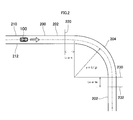
- the schematic diagram which shows the own vehicle which drive
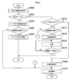
- the flowchart which shows a traveling control process.
- the characteristic view which shows the relationship between the curvature and the vehicle speed after exiting before driving
- a travel control system 2 shown in FIG. 1 includes a travel control device 10, a camera 20, a navigation device 22, a vehicle speed sensor 24, a powertrain system 30, and a brake system 32.
- the travel control device 10 is equipped with a computer including a CPU, RAM, ROM, flash memory, I / O interface, and the like, and includes a shape acquisition unit 12, a vehicle speed setting unit 14, and a vehicle speed control unit 16.
- the traveling control apparatus 10 executes a program recorded in a non-transitional tangible recording medium such as a ROM or a flash memory, thereby executing a traveling control function corresponding to the program.
- the shape acquisition unit 12 acquires the shape of the road 200 on which the host vehicle 100 travels from image data in front of the host vehicle 100 captured by the camera 20, map information of the map DB provided in the navigation device 22, or the like.
- the vehicle speed setting unit 14 sets the target speed of the vehicle 100 based on the road shape ahead of the vehicle 100 acquired by the shape acquisition unit 12. As shown in FIG. 2, when the vehicle 100 travels on a straight road 202 before entering the curved road 204 and when traveling on the straight road 202 after exiting the curved road 204, the vehicle speed setting unit 14 is defined by a road sign, for example. Set the set speed limit to the target speed.
- the vehicle speed setting unit 14 sets, for example, an upper limit speed at which the host vehicle 100 is prevented from slipping outside the curved road 204 as a target speed.
- the vehicle speed control unit 16 controls the power train system 30 and the brake system 32 so that the vehicle speed of the host vehicle 100 becomes the target speed set by the vehicle speed setting unit 14.
- the camera 20 is attached, for example, in the vicinity of the center of the mirror of the window shield in the passenger compartment of the host vehicle, and images the front of the host vehicle 100 and outputs image data.
- the navigation device 22 guides the route to the destination based on the current position of the own vehicle 100 and the destination of the own vehicle 100 input from the touch panel or the like.
- the navigation device 22 receives a positioning signal from a positioning satellite such as a GPS satellite, and maps the vehicle position based on the map information stored in the map DB.
- the map information stored in the map DB stores a road type, a road speed limit, a road curvature radius, a road gradient, and the like.
- the navigation device 22 uses the map information in the map DB and the own vehicle position detected by the navigation device 22 receiving a positioning signal from a positioning satellite such as a GPS satellite, and the speed limit of the road 200 on which the own vehicle 100 is traveling. If the road is a curve, the radius of curvature is obtained.
- a positioning satellite such as a GPS satellite
- the vehicle speed sensor 24 detects the vehicle speed of the host vehicle 100.
- the powertrain system 30 controls the opening degree of the throttle device and the fuel injection amount when the internal combustion engine is mounted as a drive source according to the drive output commanded from the vehicle speed control unit 16, and uses the motor as the drive source. If it is installed, the power supplied to the motor is controlled.
- the brake system 32 controls the actuator provided in the hydraulic circuit of the hydraulic brake according to the braking force commanded from the vehicle speed control unit 16.
- the brake system 32 controls the power supplied to the motor according to the braking force commanded from the vehicle speed control unit 16 to generate the braking force by the regenerative braking. It may be generated.
- the shape acquisition unit 12 determines whether or not it is based on at least one of image data in front of the vehicle 100 captured by the camera 20 and map information stored in a map DB included in the navigation device 22. The shape of the road 200 ahead where the car 100 travels is acquired.
- the shape acquisition unit 12 based on the image data captured by the camera 20, sets the left and right white lines 210 and 212 that define the travel path on which the host vehicle 100 travels, for example, a white line and a road surface. It detects based on the brightness
- the shape acquisition part 12 may acquire the shape of the road 200 ahead from the map information memorize
- the vehicle speed control unit 16 determines whether or not the front road is a curved road 204 based on the shape of the front road 200 acquired by the shape acquisition unit 12.
- the process proceeds to S410. If the determination in S402 is No and the road ahead is not a curved road 204 but a straight road 202, the process proceeds to S410. If the determination in S402 is Yes and the road 200 ahead is a curved road 204, in S404, the vehicle speed setting unit 14 skids to the outside of the curved road 204 when the vehicle 100 travels on the curved road 204. An upper limit speed that suppresses this is calculated. In order for the own vehicle 100 not to skid, the friction force Ft between the tire and the road surface received by the own vehicle 100 in a direction opposite to the centrifugal force Fv needs to be larger than the centrifugal force Fv received by the own vehicle 100.
- the acceleration of gravity is g
- the mass of the host vehicle 100 is M
- the vehicle speed of the host vehicle 100 is v
- the radius of curvature of the curved road 204 is r
- the friction coefficient between the host vehicle 100 and the road surface on which the host vehicle 100 travels Assuming that ⁇ , the centrifugal force Fv is expressed by the following equation (1), and the frictional force Ft is expressed by the following equation (2).
- the friction coefficient ⁇ is set on the assumption that the vehicle 100 is traveling on a wet road surface in order to suppress the side slip of the host vehicle 100 as much as possible.
- the vehicle speed setting unit 14 calculates the deceleration amount that is appropriately set based on the detection error of the sensor and the like, the road surface condition, and the vehicle speed of the host vehicle 100 within the range that satisfies the expression (4).
- the upper limit value subtracted from the speed v calculated as an equation is set as the upper limit speed of the vehicle 100.
- the vehicle speed setting unit 14 sets the upper limit speed as a target speed when the vehicle 100 travels on the curved road 204.
- the vehicle speed control unit 16 starts the vehicle 100 at a deceleration start position 220 at which the vehicle 100 starts to decelerate so that the vehicle 100 enters the curved road 204 at a constant speed when the vehicle 100 enters the curved road 204. It is determined whether or not.
- Whether or not the host vehicle 100 is at the deceleration start position 220 is determined by whether or not the host vehicle 100 is at a position Li [m] as a distance shown in FIG. To do.
- the vehicle speed control unit 16 may set a fixed value to the deceleration start position 220 represented by Li [m] and ti [sec], or a target when the current vehicle speed and the vehicle 100 travel on a curved road 204.
- the deceleration start position 220 may be set according to the difference from the speed.
- the determination in S406 is No, and Li [m] or ti [sec] to the entrance of the curved road 204 where the host vehicle 100 is the deceleration start position 220. ], It is considered that the host vehicle 100 is traveling on the curved road 204.
- the vehicle speed control unit 16 determines that the process of decelerating the host vehicle 100 from the deceleration start position 220 to the entrance of the curved road 204 has been completed in the process of S408 described later, and the process proceeds to S422. .
- the vehicle speed control unit 16 in S408, as shown in FIG.
- the own vehicle 100 enters the curved road 204, the own vehicle 100 is decelerated to the entrance of the curved road 204 so that the target speed set in S404 is reached and becomes a constant speed.
- the vehicle speed control unit 16 instructs the powertrain system 30 and the brake system 32 to control the amount of driving force and braking force to decelerate the vehicle speed of the host vehicle 100.
- the vehicle speed control unit 16 determines whether or not the vehicle 100 has exited the curved road 204 in the state of the straight road 202 instead of the curved road 204 in front of the own vehicle 100. If the determination in S410 is No and the vehicle 100 has not exited the curved road 204, it is considered that the vehicle 100 is traveling on a straight portion of the road 200. In this case, the process proceeds to S420.
- the vehicle speed control unit 16 causes the own vehicle 100 to start acceleration from the time when the own vehicle 100 exits the curved road 204. It is determined whether or not the vehicle is at the acceleration start position 230. If the determination in S412 is No, the process proceeds to S420.
- the vehicle speed control unit 16 may set the exit of the curved road 204 as shown in FIG. 2 as a fixed value at the acceleration start position 230, or a predetermined time or a predetermined distance after the own vehicle 100 exits the curve 204. May be set. Further, the vehicle speed control unit 16 may set a value input by the driver from an input device such as a display as the acceleration start position 230.
- the vehicle speed setting unit 14 sets a target speed when the vehicle 100 travels on the straight road 202 after ending acceleration after passing through the curved road 204.
- the vehicle speed setting unit 14 sets a speed limit defined by a road sign as a target speed.
- the vehicle speed control unit 16 accelerates the host vehicle 100 until the determination in S418 is Yes and the host vehicle 100 reaches the acceleration end position 232.
- the vehicle speed control unit 16 instructs the powertrain system 30 and the brake system 32 to control the amount of driving force and braking force to accelerate the vehicle speed of the host vehicle 100.
- the acceleration end position 232 is Lo [m] as the distance from the acceleration start position 230 until the vehicle speed reaches the target speed set in S414, or until the vehicle speed reaches the target speed from the acceleration start position 230. Is expressed in to [sec].
- the vehicle speed control unit 16 may set a fixed value at the acceleration end position 232 represented by Lo [m] and to [sec], and the target speed and the own vehicle when the own vehicle 100 travels on the curved road 204.
- the acceleration end position 232 may be set according to the difference from the target speed when the vehicle 100 travels on the straight road 202 through the curved road 204.
- Lo [m] is set longer than Li [m] and to [sec] is set longer than ti [sec]. Also good.
- the vehicle speed setting unit 14 sets a target speed when the host vehicle 100 travels on the straight road 202. As described above, the vehicle speed setting unit 14 sets, for example, a speed limit defined by a road sign as a target speed.
- the vehicle speed control unit 16 determines that the actual vehicle speed is the target speed based on the difference between the target speed set in S404 or S420 and the actual vehicle speed detected by the vehicle speed sensor 24. 32, the control amount of the driving force and the braking force is commanded.
- the host vehicle 100 is decelerated from the deceleration start position 220 so as to enter the curved road 204 at a constant speed when the host vehicle 100 enters the curved road 204. Further, the host vehicle 100 is accelerated from an acceleration start position 230 at which the host vehicle 100 starts to accelerate to an acceleration end position 232 when the host vehicle 100 exits the curved road 204. That is, the host vehicle 100 is not accelerated or decelerated while traveling on the curved road 204.
- the rider does not experience the inertial force due to acceleration / deceleration while the vehicle 100 is traveling on the curved road 204. It is possible to suppress discomfort felt by the passenger due to both.
- the friction coefficient used for calculating the frictional force acting in the direction opposite to the centrifugal force may be set to be appropriately variable according to the road surface condition.
- the friction coefficient may be set based on weather information acquired by communication from the outside, or the driver may input the friction coefficient to the travel control device 10 based on the weather.
- a friction coefficient for calculating a friction force acting on the opposite side to the centrifugal force may be set based on a slip ratio calculated from the vehicle speed and the tire rotation speed.
- the function executed by the traveling control device 10 is realized by software by executing a program recorded in a non-transitional physical recording medium such as a ROM or a flash memory.
- a part or all of the functions executed by the traveling control device 10 may be configured by hardware using one or a plurality of ICs.
- the traveling control device 10 When some or all of the functions of the traveling control device 10 are configured by hardware electronic circuits, they can be provided by digital circuits including a large number of logic circuits or analog circuits.
- a travel control system 2 including the travel control device 10 as a constituent element, a travel control program for causing the computer to function as the travel control device 10, and the travel control program are recorded.
- the present disclosure can also be realized in various forms such as a recording medium and a travel control method.
Landscapes
- Engineering & Computer Science (AREA)
- Transportation (AREA)
- Mechanical Engineering (AREA)
- Chemical & Material Sciences (AREA)
- Combustion & Propulsion (AREA)
- Automation & Control Theory (AREA)
- Physics & Mathematics (AREA)
- Mathematical Physics (AREA)
- Control Of Driving Devices And Active Controlling Of Vehicle (AREA)
- Regulating Braking Force (AREA)
Abstract
走行制御装置は、S400において自車の走行する道路形状を取得し、S402の判定がYesであり道路形状が直線道路からカーブした道路に変化する場合、S404において、カーブした道路を走行するときに、自車がカーブした道路の外側に横滑りすることを抑制する上限速度を目標速度として算出する。走行制御装置は、S406、S408において、自車がカーブした道路に進入する時点で一定速度でカーブした道路に進入するように減速開始位置から自車を減速させる。走行制御装置は、S410およびS412の判定がYesであり、自車がカーブした道路を抜け出て加速開始位置に達すると、S414において加速終了後の目標速度を設定し、S416~S418において、加速開始位置から加速終了位置まで自車を加速させる。
Description
本国際出願は、2015年12月4日に日本国特許庁に出願された日本国特許出願番号第2015-237545号に基づくものであって、その優先権の利益を主張するものであり、日本国特許出願番号第2015-237545号のすべての内容が参照により本明細書に組み入れられる。
本開示は、自車の車速を制御する技術に関する。
車両の走行を制御する技術として、ドライバの運転操作に対して駆動力、制動力、操舵角度等を補助的に支援する技術、およびドライバに代わってすべての走行制御を自動で行う技術など、種々の技術が知られている。
特許文献1に開示されている技術では、目標速度まで減速すべき減速地点として、カーブした道路におけるカーブの開始地点を検出している。そして、特許文献1の技術では、カーブした道路を安全に通過するために、予め設定された許容横加速度と路面摩擦係数とのいずれか値の小さい方と自車の旋回半径とを用いて、カーブした道路におけるカーブの開始地点における目標速度を設定している。
自車がカーブした道路に進入するときに減速を続けていると、減速することによる慣性力と遠心力との両方を搭乗者が体感するので、搭乗者が不快感を感じることがある。
これに対し、特許文献1の技術によると、目標速度まで減速して自車はカーブした道路に進入するので、自車がカーブした道路に進入するときに、減速することによる慣性力を搭乗者が体感することを抑制できる。
これに対し、特許文献1の技術によると、目標速度まで減速して自車はカーブした道路に進入するので、自車がカーブした道路に進入するときに、減速することによる慣性力を搭乗者が体感することを抑制できる。
しかしながら、発明者の詳細な検討の結果、カーブした道路を車両が抜け出るときに速やかに車両の加速を完了するために、カーブした道路を車両が抜け出る前に車両の加速を開始すると、車両の搭乗者は加速することによる慣性力と遠心力との両方を体感するので、搭乗者が不快感を感じることがあるという課題が見出された。
本開示の一側面は、車両がカーブした道路に進入するときとカーブした道路から抜け出るときとに車両の搭乗者が感じる不快感を抑制する技術を提供する。
本開示の一態様である走行制御装置は、形状取得部と、車速制御部と、を備えている。
本開示の一態様である走行制御装置は、形状取得部と、車速制御部と、を備えている。
形状取得部は、自車の走行する道路形状を取得する。車速制御部は、形状取得部が取得する道路形状が直線道路からカーブした道路に変化する場合、自車がカーブした道路に進入する時点で一定速度でカーブした道路に進入するように自車に減速を開始させる減速開始位置を設定し、形状取得部が取得する道路形状がカーブした道路から直線道路に変化する場合、自車がカーブした道路を抜け出た時点から自車に加速を開始させる加速開始位置を設定する。
この構成によれば、自車がカーブした道路に進入する前に車速を減速させて一定速度でカーブした道路に進入するので、自車がカーブした道路に進入するときには、自車の搭乗者は、減速による慣性力を体感しない。
また、自車がカーブした道路を抜け出てから自車を加速させるので、自車の搭乗者は、自車がカーブした道路から抜け出るときには加速することによる慣性力を体感せず、自車がカーブした道路から抜け出て加速するときには遠心力を体感しない。
したがって、本開示の一態様では、自車がカーブした道路に進入するときと、自車がカーブした道路を抜け出るときとにおいて、自車の搭乗者が受ける不快感を抑制できる。
尚、特許請求の範囲に記載した括弧内の符号は、一つの態様として後述する実施形態に記載の具体的手段との対応関係を示すものであって、本開示の技術的範囲を限定するものではない。
尚、特許請求の範囲に記載した括弧内の符号は、一つの態様として後述する実施形態に記載の具体的手段との対応関係を示すものであって、本開示の技術的範囲を限定するものではない。
以下、本開示が適用された実施形態を図に基づいて説明する。
[1.構成]
図1に示す走行制御システム2は、走行制御装置10と、カメラ20と、ナビゲーション装置22と、車速センサ24と、パワートレインシステム30と、ブレーキシステム32とを備えている。
[1.構成]
図1に示す走行制御システム2は、走行制御装置10と、カメラ20と、ナビゲーション装置22と、車速センサ24と、パワートレインシステム30と、ブレーキシステム32とを備えている。
走行制御装置10は、CPU、RAM、ROM、フラッシュメモリ、I/Oインタフェース等を備えるコンピュータを搭載しており、形状取得部12と車速設定部14と車速制御部16とを備えている。走行制御装置10は、ROMまたはフラッシュメモリ等の非遷移的実体的記録媒体に記録されているプログラムを実行することにより、プログラムに対応する走行制御の機能を実行する。
形状取得部12は、カメラ20が撮像する自車100の前方の画像データ、あるいはナビゲーション装置22が備える地図DBの地図情報等から、自車100が走行する道路200の形状を取得する。
車速設定部14は、形状取得部12が取得する自車100の前方の道路形状に基づき、自車100の目標速度を設定する。図2に示すように、自車100がカーブした道路204に進入する前とカーブした道路204を抜け出てから直線道路202を走行する場合とには、車速設定部14は、例えば道路標識で規定されている制限速度を目標速度に設定する。
自車100がカーブした道路204を走行する場合、車速設定部14は、例えば、自車100がカーブした道路204の外側に横滑りすることを抑制する上限速度を目標速度に設定する。
車速制御部16は、自車100の車速が車速設定部14が設定した目標速度となるように、パワートレインシステム30とブレーキシステム32とを制御する。カメラ20は、例えば自車両の車室内のウィンドウシールドのミラーの中央付近に取り付けられており、自車100の前方を撮像して画像データを出力する。
ナビゲーション装置22は、自車100の現在位置とタッチパネル等から入力される自車100の目的地とに基づき、目的地までの経路を案内する。ナビゲーション装置22は、GPS衛星等の測位衛星から測位信号を受信して、自車位置を地図DBに記憶されている地図情報に基づいてマッピングする。地図DBに記憶されている地図情報には、道路種別、道路の制限速度、道路の曲率半径、道路の勾配等が記憶されている。
ナビゲーション装置22は、地図DBの地図情報とナビゲーション装置22がGPS衛星等の測位衛星から測位信号を受信して検出する自車位置とから、自車100が走行している道路200の制限速度と、道路がカーブであれば曲率半径とを取得する。
車速センサ24は、自車100の車速を検出する。
パワートレインシステム30は、車速制御部16から指令される駆動出力にしたがって、駆動源として内燃機関を搭載している場合にはスロットル装置の開度および燃料噴射量を制御し、駆動源としてモータを搭載している場合にはモータへの供給電力を制御する。
パワートレインシステム30は、車速制御部16から指令される駆動出力にしたがって、駆動源として内燃機関を搭載している場合にはスロットル装置の開度および燃料噴射量を制御し、駆動源としてモータを搭載している場合にはモータへの供給電力を制御する。
ブレーキシステム32は、車速制御部16から指令される制動力にしたがって、油圧式ブレーキの液圧回路に設けられたアクチュエータを制御する。自車100が駆動源としてモータを搭載している場合には、ブレーキシステム32は、車速制御部16から指令される制動力にしたがって、モータへの供給電力を制御して回生ブレーキによる制動力を生成してもよい。
[2.処理]
以下、走行制御装置10が実行する走行制御処理を、図3のフローチャートに基づいて説明する。図3のフローチャートは所定時間間隔で常時実行される。
以下、走行制御装置10が実行する走行制御処理を、図3のフローチャートに基づいて説明する。図3のフローチャートは所定時間間隔で常時実行される。
S400において形状取得部12は、カメラ20が撮像する自車100の前方の画像データと、ナビゲーション装置22が備える地図DBが記憶している地図情報とのうち少なくともいずれか一つに基づいて、自車100が走行する前方の道路200の形状を取得する。
例えば、形状取得部12は、カメラ20が撮像する画像データに基づいて、図2に示すように、自車100が走行する走行路を規定する左右の白線210、212を、例えば白線と路面との輝度差に基づいて検出する。そして、形状取得部12は、例えば検出した左右の白線210、212の座標に基づいて前方の道路200の曲率(ρ)および曲率半径(r)を算出する。
また、形状取得部12は、地図DBに記憶されている地図情報と測位衛星の測位信号から検出する自車位置とから、前方の道路200の形状を取得してもよい。
S402において車速制御部16は、形状取得部12が取得した前方の道路200の形状に基づいて、前方の道路がカーブした道路204であるか否かを判定する。
S402において車速制御部16は、形状取得部12が取得した前方の道路200の形状に基づいて、前方の道路がカーブした道路204であるか否かを判定する。
S402の判定がNoであり前方の道路がカーブした道路204ではなく直線道路202の場合、処理はS410に移行する。
S402の判定がYesであり前方の道路200がカーブした道路204の場合、S404において、車速設定部14は、カーブした道路204を走行するときに、自車100がカーブした道路204の外側に横滑りすることを抑制する上限速度を算出する。自車100が横滑りしないためには、自車100が受ける遠心力Fvよりも、遠心力Fvと反対方向に自車100が受けるタイヤと路面との摩擦力Ftが大きくなる必要がある。
S402の判定がYesであり前方の道路200がカーブした道路204の場合、S404において、車速設定部14は、カーブした道路204を走行するときに、自車100がカーブした道路204の外側に横滑りすることを抑制する上限速度を算出する。自車100が横滑りしないためには、自車100が受ける遠心力Fvよりも、遠心力Fvと反対方向に自車100が受けるタイヤと路面との摩擦力Ftが大きくなる必要がある。
ここで、重力加速度をg、自車100の質量をM、自車100の車速をv、カーブした道路204の曲率半径をr、自車100と自車100が走行する路面との摩擦係数をμとすると、遠心力Fvは次式(1)で表わされ、摩擦力Ftは次式(2)で表わされる。摩擦係数μは、例えば、自車100の横滑りを極力抑制するために、濡れた路面を走行する場合を想定して設定されている。
Fv=Mv2/r ・・・(1)
Ft=μMg ・・・(2)
そして、次式(3)の関係から、次式(4)を満たす速度範囲であれば、自車100がカーブした道路204の外側に横滑りすることを抑制できる。
Ft=μMg ・・・(2)
そして、次式(3)の関係から、次式(4)を満たす速度範囲であれば、自車100がカーブした道路204の外側に横滑りすることを抑制できる。
Fv=Mv2/r<Ft=μMg ・・・(3)
v2/r<μg ・・・(4)
S404において、車速設定部14は、式(4)を満たす範囲内で、センサ等の検出誤差、ならびに路面状態および自車の100の車速に基づいて適宜設定する減速分を、式(4)を等式として算出した速度vから減算した上限値を自車100の上限速度として設定する。車速設定部14は、上限速度を、自車100がカーブした道路204を走行するときの目標速度として設定する。
v2/r<μg ・・・(4)
S404において、車速設定部14は、式(4)を満たす範囲内で、センサ等の検出誤差、ならびに路面状態および自車の100の車速に基づいて適宜設定する減速分を、式(4)を等式として算出した速度vから減算した上限値を自車100の上限速度として設定する。車速設定部14は、上限速度を、自車100がカーブした道路204を走行するときの目標速度として設定する。
S406において車速制御部16は、自車100がカーブした道路204に進入する時点で一定速度でカーブした道路204に進入するように自車100に減速を開始させる減速開始位置220に自車100がいるか否かを判定する。
自車100が減速開始位置220にいるか否かは、自車100がカーブした道路204の入口まで図2に示す距離としてLi[m]または時間としてti[sec]の位置にいるか否かで判定する。車速制御部16は、Li[m]およびti[sec]が表す減速開始位置220に固定値を設定してもよいし、現在の車速と自車100がカーブした道路204を走行するときの目標速度との差に応じて減速開始位置220を設定してもよい。
自車100の前方にカーブした道路204が存在している状態で、S406の判定がNoであり、自車100が減速開始位置220としてカーブした道路204の入口までLi[m]またはti[sec]の位置にいない場合、自車100はカーブした道路204を走行中であると考えられる。
この場合、車速制御部16は、後述するS408の処理で、減速開始位置220からカーブした道路204の入り口まで自車100を減速させる処理が終了していると判断し、処理をS422に移行する。
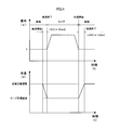
自車100の前方にカーブした道路204が存在している状態で、S406の判定がYesであり、自車100が減速開始位置220にいる場合、S408において車速制御部16は、図4に示すように、自車100がカーブした道路204に進入する時点でS404において設定した目標速度に達して一定速度になるように、カーブした道路204の入り口まで自車100を減速させる。車速制御部16は、パワートレインシステム30とブレーキシステム32とに対し、駆動力と制動力との制御量を指令して自車100の車速を減速させる。
S410において車速制御部16は、自車100の前方の道路200がカーブした道路204ではなく直線道路202の状態で自車100がカーブした道路204を抜け出たか否かを判定する。S410の判定がNoであり自車100がカーブした道路204を抜け出ていない場合、自車100は道路200の直線部分を走行していると考えられる。この場合、処理はS420に移行する。
S410の判定がYesであり自車100がカーブした道路204を抜け出ている場合、S412において車速制御部16は、自車100がカーブした道路204を抜け出た時点から自車100に加速を開始させる加速開始位置230にいるか否かを判定する。S412の判定がNoの場合、処理はS420に移行する。
車速制御部16は、加速開始位置230に固定値として、図2に示すようにカーブした道路204の出口を設定してもよいし、自車100がカーブ204を抜け出てから所定時間または所定距離を設定してもよい。また、車速制御部16は、加速開始位置230として、ドライバがディスプレイ等の入力装置から入力する値を設定してもよい。
S412の判定がYesの場合、S414において車速設定部14は、自車100がカーブした道路204を抜けてから加速を終了した後に直線道路202を走行するときの目標速度を設定する。例えば、車速設定部14は、道路標識で規定される制限速度を目標速度として設定する。
S416において車速制御部16は、S418の判定がYesになり自車100が加速終了位置232に達するまで自車100を加速させる。車速制御部16は、パワートレインシステム30とブレーキシステム32とに対し、駆動力と制動力との制御量を指令して自車100の車速を加速させる。
図2に示すように加速終了位置232は、車速がS414で設定した目標速度になるまでの加速開始位置230からの距離としてLo[m]、あるいは加速開始位置230から車速が目標速度に達するまでに要する時間としてto[sec]で表される。
車速制御部16は、Lo[m]およびto[sec]が表す加速終了位置232に固定値を設定してもよいし、自車100がカーブした道路204を走行するときの目標速度と自車100がカーブした道路204を通過して直線道路202を走行するときの目標速度との差に応じて加速終了位置232を設定してもよい。
また、ブレーキ操作による減速よりも、アクセル操作による加速の方が長い時間を要するので、Li[m]よりもLo[m]を長く、ti[sec]よりもto[sec]を長く設定してもよい。
S420において車速設定部14は、自車100が直線道路202を走行するときの目標速度を設定する。前述したように、車速設定部14は、例えば道路標識で規定される制限速度を目標速度として設定する。
S422において車速制御部16は、S404またはS420で設定された目標速度と車速センサ24が検出する実車速との差に基づいて、実車速を目標速度にするために、パワートレインシステム30とブレーキシステム32とに対し、駆動力と制動力との制御量を指令する。
[3.効果]
以上説明した上記実施形態では、自車100がカーブした道路204に進入する時点で一定速度でカーブした道路204に進入するように減速開始位置220から自車100を減速させる。さらに、自車100がカーブした道路204を抜け出た時点から自車100に加速を開始させる加速開始位置230から加速終了位置232まで自車100を加速させる。つまり、自車100がカーブした道路204を走行中は自車100の加減速は行われない。
以上説明した上記実施形態では、自車100がカーブした道路204に進入する時点で一定速度でカーブした道路204に進入するように減速開始位置220から自車100を減速させる。さらに、自車100がカーブした道路204を抜け出た時点から自車100に加速を開始させる加速開始位置230から加速終了位置232まで自車100を加速させる。つまり、自車100がカーブした道路204を走行中は自車100の加減速は行われない。
これにより、自車100がカーブした道路204を走行中は加減速による慣性力を搭乗者が体感しないので、自車100がカーブした道路204を走行中に、遠心力と加減速による慣性力との両方に起因して搭乗者が感じる不快感を抑制できる。
[4.他の実施形態]
(1)遠心力と反対方向に働く摩擦力を算出するために使用される摩擦係数は、路面状態に応じて適宜可変に設定してもよい。例えば、外部から通信により取得する天気情報に基づいて摩擦係数を設定してもよいし、天候に基づいてドライバが摩擦係数を走行制御装置10に入力してもよい。また、車速とタイヤの回転速度とから算出するスリップ率に基づいて、遠心力と反対側に働く摩擦力を算出する場合の摩擦係数を設定してもよい。
(1)遠心力と反対方向に働く摩擦力を算出するために使用される摩擦係数は、路面状態に応じて適宜可変に設定してもよい。例えば、外部から通信により取得する天気情報に基づいて摩擦係数を設定してもよいし、天候に基づいてドライバが摩擦係数を走行制御装置10に入力してもよい。また、車速とタイヤの回転速度とから算出するスリップ率に基づいて、遠心力と反対側に働く摩擦力を算出する場合の摩擦係数を設定してもよい。
(2)上記実施形態では、走行制御装置10が実行する機能を、ROMまたはフラッシュメモリ等の非遷移的実体的記録媒体に記録されているプログラムを実行することによりソフトウェアで実現した。これに対し、走行制御装置10が実行する機能の一部またはすべてを、一つまたは複数のIC等によりハードウェア的に構成してもよい。
走行制御装置10の機能の一部またはすべてをハードウェアである電子回路によって構成する場合、それは多数の論理回路を含むデジタル回路、またはアナログ回路によって提供することができる。
(3)上記実施形態における1つの構成要素が有する機能を複数の構成要素として分散させたり、複数の構成要素が有する機能を1つの構成要素に統合させたりしてもよい。また、上記実施形態の構成の一部を省略してもよい。また、上記実施形態の構成の少なくとも一部を、他の上記実施形態の構成に対して付加又は置換してもよい。尚、特許請求の範囲に記載した文言のみによって特定される技術思想に含まれるあらゆる態様が本開示の実施形態である。
(4)上述した走行制御装置10の他、当該走行制御装置10を構成要素とする走行制御システム2、当該走行制御装置10としてコンピュータを機能させるための走行制御プログラム、この走行制御プログラムを記録した記録媒体、走行制御方法など、種々の形態で本開示を実現することもできる。
Claims (6)
- 走行制御装置(10)であって、
自車(100)の走行する道路形状を取得する形状取得部(12、S400)と、
前記形状取得部が取得する前記道路形状が直線道路(202)からカーブした道路(204)に変化する場合、前記自車が前記カーブした道路に進入する時点で一定速度で前記カーブした道路に進入するように前記自車に減速を開始させる減速開始位置(220)を設定し、前記形状取得部が取得する前記道路形状が前記カーブした道路から前記直線道路に変化する場合、前記自車が前記カーブした道路を抜け出た時点から前記自車に加速を開始させる加速開始位置(230)を設定する車速制御部(16、S402、S406~S412、S416、S418、S422)と、
を備える走行制御装置。 - 請求項1に記載の走行制御装置において、
前記形状取得部は、地図情報またはカメラ(20)が撮像する前記自車の前方の画像データから前記道路形状を取得する、
走行制御装置。 - 請求項1または2に記載の走行制御装置において、
前記車速制御部は、前記減速開始位置から前記自車が前記カーブした道路に進入するまでの時間と前記加速開始位置から前記自車に加速を終了させる加速終了位置(232)までの時間とを、あるいは前記減速開始位置から前記自車が前記カーブした道路に進入するまでの距離と前記加速開始位置から前記加速終了位置までの距離とを、異なる値に設定する、
走行制御装置。 - 請求項1から3のいずれか一項に記載の走行制御装置において、
前記車速制御部は、前記減速開始位置から前記自車が前記カーブした道路に進入するまでの時間と前記加速開始位置から前記自車に加速を終了させる加速終了位置(232)までの時間とを、あるいは前記減速開始位置から前記自車が前記カーブした道路に進入するまでの距離と前記加速開始位置から前記加速終了位置までの距離とを、前記車速に基づいて設定する、
走行制御装置。 - 請求項4に記載の走行制御装置において、
前記車速制御部は、前記加速開始位置から前記加速終了位置までの時間を前記減速開始位置から前記自車が前記カーブした道路に進入するまでの時間よりも、あるいは前記加速開始位置から前記加速終了位置までの距離を前記減速開始位置から前記自車が前記カーブした道路に進入するまでの距離よりも、長く設定する、
走行制御装置。 - 請求項1から5のいずれか一項に記載の走行制御装置において、
前記カーブした道路を走行するときに前記自車が受ける遠心力よりも前記遠心力と反対方向に前記自車が受ける摩擦力が大きくなるように、前記一定速度を設定する車速設定部(14、S404)をさらに備える、
走行制御装置。
Priority Applications (1)
| Application Number | Priority Date | Filing Date | Title |
|---|---|---|---|
| US15/780,340 US20180362001A1 (en) | 2015-12-04 | 2016-12-02 | Traveling control apparatus |
Applications Claiming Priority (2)
| Application Number | Priority Date | Filing Date | Title |
|---|---|---|---|
| JP2015-237545 | 2015-12-04 | ||
| JP2015237545A JP2017100655A (ja) | 2015-12-04 | 2015-12-04 | 走行制御装置 |
Publications (1)
| Publication Number | Publication Date |
|---|---|
| WO2017094906A1 true WO2017094906A1 (ja) | 2017-06-08 |
Family
ID=58797437
Family Applications (1)
| Application Number | Title | Priority Date | Filing Date |
|---|---|---|---|
| PCT/JP2016/085969 Ceased WO2017094906A1 (ja) | 2015-12-04 | 2016-12-02 | 走行制御装置 |
Country Status (3)
| Country | Link |
|---|---|
| US (1) | US20180362001A1 (ja) |
| JP (1) | JP2017100655A (ja) |
| WO (1) | WO2017094906A1 (ja) |
Families Citing this family (9)
| Publication number | Priority date | Publication date | Assignee | Title |
|---|---|---|---|---|
| JP6460349B2 (ja) * | 2016-04-13 | 2019-01-30 | トヨタ自動車株式会社 | 車両走行制御装置 |
| JP2019036036A (ja) * | 2017-08-10 | 2019-03-07 | 日産自動車株式会社 | 搬送システムの走行制御方法及び走行制御装置 |
| JP2019196130A (ja) * | 2018-05-11 | 2019-11-14 | ジヤトコ株式会社 | 車両制御装置 |
| FR3093305B1 (fr) | 2019-02-28 | 2021-01-29 | Psa Automobiles Sa | Régulation de la vitesse d’un véhicule lors d’un dépassement en virage |
| JP7230795B2 (ja) * | 2019-12-25 | 2023-03-01 | トヨタ自動車株式会社 | 車両制御装置 |
| US12344248B2 (en) * | 2020-08-20 | 2025-07-01 | Nissan Motor Co., Ltd. | Method and device for controlling vehicle acceleration on a curved road using curve information |
| US12110019B2 (en) * | 2021-01-11 | 2024-10-08 | Hyundai Mobis Co., Ltd. | Vehicle driving control system and method |
| FR3141912B1 (fr) * | 2022-11-14 | 2025-08-29 | Psa Automobiles Sa | Gestion de la vitesse d’un véhicule automobile dans un virage |
| JP2025017698A (ja) * | 2023-07-25 | 2025-02-06 | 日立Astemo株式会社 | 車両運動制御装置、および、車両運動制御方法 |
Citations (3)
| Publication number | Priority date | Publication date | Assignee | Title |
|---|---|---|---|---|
| JP2005189044A (ja) * | 2003-12-25 | 2005-07-14 | Toyota Motor Corp | 車両用評価装置、車両用評価機能を有する車両制御装置、車両用評価方法、およびプログラム |
| JP2006347528A (ja) * | 2005-05-16 | 2006-12-28 | Xanavi Informatics Corp | 自動車の走行制御装置及び方法 |
| WO2009101769A1 (ja) * | 2008-02-15 | 2009-08-20 | Aisin Aw Co., Ltd. | 運転支援装置、運転支援方法および運転支援プログラム |
Family Cites Families (3)
| Publication number | Priority date | Publication date | Assignee | Title |
|---|---|---|---|---|
| JP5056220B2 (ja) * | 2006-09-29 | 2012-10-24 | 日産自動車株式会社 | 走行制御装置 |
| JP5336052B2 (ja) * | 2007-05-28 | 2013-11-06 | 株式会社デンソー | クルーズ制御装置、プログラム、及び目標車速の設定方法 |
| JP6095780B2 (ja) * | 2012-08-16 | 2017-03-15 | ジャガー ランド ローバー リミテッドJaguar Land Rover Limited | 車両の速度制御システムを操作する方法、および車両の速度を制御するシステム |
-
2015
- 2015-12-04 JP JP2015237545A patent/JP2017100655A/ja active Pending
-
2016
- 2016-12-02 US US15/780,340 patent/US20180362001A1/en not_active Abandoned
- 2016-12-02 WO PCT/JP2016/085969 patent/WO2017094906A1/ja not_active Ceased
Patent Citations (3)
| Publication number | Priority date | Publication date | Assignee | Title |
|---|---|---|---|---|
| JP2005189044A (ja) * | 2003-12-25 | 2005-07-14 | Toyota Motor Corp | 車両用評価装置、車両用評価機能を有する車両制御装置、車両用評価方法、およびプログラム |
| JP2006347528A (ja) * | 2005-05-16 | 2006-12-28 | Xanavi Informatics Corp | 自動車の走行制御装置及び方法 |
| WO2009101769A1 (ja) * | 2008-02-15 | 2009-08-20 | Aisin Aw Co., Ltd. | 運転支援装置、運転支援方法および運転支援プログラム |
Also Published As
| Publication number | Publication date |
|---|---|
| US20180362001A1 (en) | 2018-12-20 |
| JP2017100655A (ja) | 2017-06-08 |
Similar Documents
| Publication | Publication Date | Title |
|---|---|---|
| WO2017094906A1 (ja) | 走行制御装置 | |
| CN106515734B (zh) | 用于机动车辆中自动适应加速的方法 | |
| CN106166951B (zh) | 车速限制装置以及车速控制装置 | |
| KR101646369B1 (ko) | 하이브리드 차량의 타력주행 유도 제어장치 및 방법 | |
| CN107107751B (zh) | 目标车速生成装置及行驶控制装置 | |
| JP5990941B2 (ja) | 車間距離制御装置及び車間距離制御方法 | |
| JP4541973B2 (ja) | 運転支援装置および運転支援方法 | |
| JP6319192B2 (ja) | 車速制限装置 | |
| US20130261889A1 (en) | Adaptive cruise control apparatus | |
| US9969394B2 (en) | Distance regulating system, motor vehicle and computer program product | |
| JP2001052298A (ja) | カーブ進入制御装置 | |
| CN108016438A (zh) | 车辆控制装置、车辆控制方法以及存储介质 | |
| JP2011000935A (ja) | 車両用速度制御装置 | |
| JP7204437B2 (ja) | 車両走行制御方法及び車両走行制御システム | |
| US20160293010A1 (en) | Collision-avoidance support device | |
| CN104737216A (zh) | 驾驶辅助装置 | |
| KR20190043416A (ko) | 환경차의 크립 토크 제어 장치 및 방법 | |
| JP4277907B2 (ja) | 自動車の走行制御装置 | |
| JP2019209701A (ja) | 車両制御装置および車両制御方法 | |
| JP6659513B2 (ja) | 車両制御装置、車両制御方法、および車両制御プログラム | |
| JP2017132406A (ja) | 車両の制御装置及び車両の制御方法 | |
| CN112955356A (zh) | 停车辅助装置及停车辅助方法 | |
| JP5377026B2 (ja) | 追従走行制御装置 | |
| JP6119526B2 (ja) | 車両用走行制御装置 | |
| JP2017100653A (ja) | 走行制御装置 |
Legal Events
| Date | Code | Title | Description |
|---|---|---|---|
| 121 | Ep: the epo has been informed by wipo that ep was designated in this application |
Ref document number: 16870841 Country of ref document: EP Kind code of ref document: A1 |
|
| NENP | Non-entry into the national phase |
Ref country code: DE |
|
| 122 | Ep: pct application non-entry in european phase |
Ref document number: 16870841 Country of ref document: EP Kind code of ref document: A1 |