WO2017094773A1 - 線量割出装置、線量割出方法および線量割出機能付き測定装置 - Google Patents
線量割出装置、線量割出方法および線量割出機能付き測定装置 Download PDFInfo
- Publication number
- WO2017094773A1 WO2017094773A1 PCT/JP2016/085546 JP2016085546W WO2017094773A1 WO 2017094773 A1 WO2017094773 A1 WO 2017094773A1 JP 2016085546 W JP2016085546 W JP 2016085546W WO 2017094773 A1 WO2017094773 A1 WO 2017094773A1
- Authority
- WO
- WIPO (PCT)
- Prior art keywords
- dose
- unit
- zero point
- conversion element
- integrated
- Prior art date
- Legal status (The legal status is an assumption and is not a legal conclusion. Google has not performed a legal analysis and makes no representation as to the accuracy of the status listed.)
- Ceased
Links
Images





Classifications
-
- G—PHYSICS
- G01—MEASURING; TESTING
- G01T—MEASUREMENT OF NUCLEAR OR X-RADIATION
- G01T1/00—Measuring X-radiation, gamma radiation, corpuscular radiation, or cosmic radiation
- G01T1/02—Dosimeters
- G01T1/026—Semiconductor dose-rate meters
-
- G—PHYSICS
- G01—MEASURING; TESTING
- G01T—MEASUREMENT OF NUCLEAR OR X-RADIATION
- G01T1/00—Measuring X-radiation, gamma radiation, corpuscular radiation, or cosmic radiation
- G01T1/02—Dosimeters
-
- G—PHYSICS
- G01—MEASURING; TESTING
- G01F—MEASURING VOLUME, VOLUME FLOW, MASS FLOW OR LIQUID LEVEL; METERING BY VOLUME
- G01F23/00—Indicating or measuring liquid level or level of fluent solid material, e.g. indicating in terms of volume or indicating by means of an alarm
-
- G—PHYSICS
- G01—MEASURING; TESTING
- G01T—MEASUREMENT OF NUCLEAR OR X-RADIATION
- G01T1/00—Measuring X-radiation, gamma radiation, corpuscular radiation, or cosmic radiation
- G01T1/16—Measuring radiation intensity
Definitions
- the present invention relates to a dose indexing technique at a detection point by a detection device that detects a specific physical quantity.
- the required information is, for example, information relating to physical quantities such as the pressure in the facility, the temperature, or the water level of the liquid accumulated in the facility.
- the physical quantity to be detected is often detected in the form of a voltage at the detector.
- the detected voltage transmission method is roughly classified into a method of transmitting the voltage as it is and a method of transmitting the voltage as a current by V / I conversion.
- the method of transmitting information in the form of current is characterized in that the influence of noise is smaller than when the voltage is transmitted when the transmission distance is long.
- the indicated value displayed due to a change in the elasticity of a spring inside the measuring device may deviate from the true value due to long-term use. Therefore, in general, the indicated value is calibrated at a specific time such as when the detector is installed or every predetermined period after installation.
- Zero point calibration is calibration in which the indicated value becomes zero when the voltage input to the V / I conversion element is zero.
- the amount of current output from the V / I conversion element when the voltage input to the V / I conversion element is zero is hereinafter referred to as “zero point current”.
- Span calibration is calibration in which when a plurality of known voltages are input to the V / I conversion element, the indicated value indicates the true value of the physical quantity at each input voltage.
- the amount of deviation from the true value of the current value output from the V / I conversion element with respect to the applied known voltage is hereinafter referred to as “span deviation”.
- detection devices installed in difficult-to-access locations are difficult to replace and repair frequently, in addition to the simple structure and high durability, one unit can acquire as much information as possible.
- a detection device installed in a radioactively contaminated facility is highly demanded to acquire a radiation dose. By acquiring information on the radiation dose, it is possible not only to grasp the radiation dose in the facility, but also to know when to replace the detection device based on the exposure dose.
- the present invention has been made in consideration of such circumstances, and is a dose indexing device that can determine the radiation dose at a detection point without adding a new device to a detector that detects a specific physical quantity,
- An object is to provide an indexing method and a measuring apparatus with a dose indexing function.
- the dose indexing device is a dose indexing device that is mounted on a measuring device that converts a detected specific physical quantity from a voltage to a current by a V / I conversion element and transmits it.
- Correlation holding unit holding zero point shift data indicating the correlation between dose and zero point current, and span shift data indicating the correlation between integrated dose and deviation, and the zero point current and zero point recorded in the recording unit
- a first estimation unit that estimates at least one integrated dose of the V / I conversion element based on the shift data, and an integrated illumination of the V / I conversion element based on the shift amount and span shift data recorded in the recording unit.
- a second estimation unit that estimates at least one dose, and a comparison unit that compares the integrated doses estimated by the first estimation unit and the second estimation unit, respectively, and
- the measuring apparatus with a dose indexing function includes a detector that detects a specific physical quantity as a voltage, a V / I conversion element that converts the physical quantity from voltage to current, and irradiation with radiation.
- a recording unit that records the zero point current output by the I conversion element when no voltage is input and the amount of deviation from the true value of the current value that is output with respect to a given voltage, and the cumulative radiation dose acquired in advance.
- Correlation holding unit that holds zero point shift data indicating the correlation between the current and the zero point current, and span shift data indicating the correlation between the integrated irradiation amount and the deviation amount, and the zero point current and zero point shift recorded in the recording unit
- a first estimator for estimating at least one integrated dose of the V / I conversion element based on the data; and an integrated irradiation of the V / I converter based on the shift amount and span shift data recorded in the recording unit.
- a second estimating unit that estimates at least one, a comparing unit that identifies the integrated integrated dose as a true integrated dose by comparing the integrated dose estimated by each of the first and second estimating units, Is provided.
- the dose indexing method is a dose indexing method using a measurement device that converts a detected specific physical quantity from voltage to current by a V / I conversion element and transmits it.
- a step of acquiring a zero point current output by the V / I conversion element when no voltage is input and a deviation amount from a true value of a current value output with respect to a given known voltage, and cumulative irradiation of radiation acquired in advance Based on the zero point shift data indicating the correlation between the dose and the zero point current, and the span shift data indicating the correlation between the integrated irradiation amount and the deviation amount, and the recorded zero point current and zero point shift data.
- the cumulative dose of the V / I conversion element is reduced.
- FIG. 1 is a schematic configuration diagram of a dose indexing device according to a first embodiment and a measurement device to which the dose indexing device is applied.
- A The figure which shows an example of zero point shift data
- B The figure which shows an example of span shift data.
- shift amount The flowchart which shows the dose indexing method concerning 1st Embodiment.
- the schematic block diagram of the measuring apparatus with a dose indexing function concerning 3rd Embodiment The figure which shows an example of the detector provided with the immersion part of the auxiliary
- indexing device 50 a measurement apparatus 10 to which a dose indexing device 50 (hereinafter simply referred to as “indexing device 50”) is applied will be described with reference to FIGS.
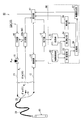
- FIG. 1 is a schematic configuration diagram of an indexing device 50 according to the first embodiment and a measuring device 10 to which the indexing device 50 is applied.
- the measuring device 10 to which the indexing device 50 is applied is installed in a facility where the detector 20 is radioactively contaminated.
- the measuring apparatus 10 converts the physical quantity detected by the detector 20 in the form of voltage into current, and transmits it remotely in the form of current.
- the measuring device 10 is, for example, a throw-in water level meter 10A that measures the water level of the coolant that has been released and accumulated in the nuclear power plant during a natural disaster.
- the throwing water level gauge 10A will be described as an example of the measuring device 10.
- the measuring device 10 is not limited to the example of the throwing water level meter 10A.
- a detector 20 thrown into the liquid is connected to a conversion unit 14 via a signal line 13.
- the conversion unit 14 is connected to the display unit 17 in the central control room, for example.
- the conversion unit 14 performs I / V conversion on the current related to the water level of the liquid received from the detector 20 and transmits the converted current to the display unit 17.
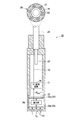
- FIG. 2 is a schematic cross-sectional view of the detector 20 provided in the throwing water level gauge 10A.
- the detector 20 has a cylindrical outer shape by a casing 21 in which a water inlet hole 24 is provided on one bottom surface.
- a pressure sensor 22 is installed in the vicinity of the bottom surface where the water inlet hole 24 is provided so as to seal the housing 21.
- the inside of the housing 21 is isolated from the surrounding liquid by the pressure sensor 22, and no liquid enters the inside further from the pressure sensor 22.
- a hollow cable 23 is connected to the other bottom surface where the water inlet hole 24 is not provided.
- the hollow cable 23 is covered with the signal line 13 and the reinforcing line 18 to become a transmission line 29 and is laid down to the water.
- the hollow cable 23 is normally opened to the atmosphere through an opening on the water, and the inside of the housing 21 is maintained at the atmospheric pressure Patm . That is, one side facing the inside of the casing 21 receives the atmospheric pressure Patm .
- the other surface in contact with the liquid of the pressure sensor 22 undergoes a pressure P w.
- a pressure sensor 22 for example, a sensor using a diaphragm 25 that converts the pressure applied to the diaphragm into the magnitude of an electric signal is widely used.
- the diaphragm is an elastic diaphragm, and the degree of expansion and dent of the diaphragm due to pressure is read.
- a method of electrically reading this degree there are a semiconductor strain gage type in which strain is sensed by a piezoelectric element installed in the diaphragm 25 or a capacitance type in which displacement is sensed.
- Hydraulically P w water pressure side diaphragm 25b is subjected to a pressure sensor 22, differential pressure ⁇ P between the atmospheric pressure P atm to receive the reference pressure side diaphragm 25a via the hollow cable 23 (FIG. 10), the difference portion is converted into a voltage 26 is read.
- a detector that measures water pressure using a spring (not shown) instead of using the diaphragm 25 operates similarly as the detector 20.
- the read voltage is converted into a current by the V / I conversion element 28 and output to the signal line 13 to which the conversion unit 14 is connected as shown in FIG.
- the electrical signal based on the differential pressure ⁇ P transmitted from the V / I conversion element 28 is converted into a voltage by the conversion unit 14 and displayed on the display unit 17 as the liquid level.
- the indicated value of the water level because it is intended to be calculated based on the pressure, such as water pressure P w as described above, may deviate from the actual water level. Therefore, a known pressure is applied to the reference pressure side diaphragm 25a (25) at a predetermined time, and the indicated value is calibrated such as zero point calibration or span calibration. The applied pressure is controlled in accordance with, for example, a worker instruction transmitted from the display unit 17 to the application unit 16.
- the application unit 16 is connected to the hollow cable 23 via the three-way valve 19.
- the indexing device 50 will be described with reference to FIG.
- the indexing device 50 includes a recording unit 51, a correlation holding unit 52, a first estimation unit 53, a second estimation unit 54, a comparison unit 56, and a calculation unit 57 (see FIG. 1 includes a dose calculation unit 57) and a warning unit 58.
- the recording unit 51 records and accumulates the zero point current and the span shift amount (hereinafter, the zero point current and the span shift amount are collectively referred to as “shift amount”).
- shift amount the current output from the V / I conversion element 28 changes irreversibly and becomes a shift amount.
- the mechanical strength of the display mechanism for displaying the physical quantity in the measuring apparatus 10 is sufficient, the shift amount due to the deterioration of the display mechanism can be ignored. In this way, when other elements that generate the shift amount can be ignored or removed, it can be said that the generation of the shift amount is caused by radiation irradiation. Therefore, the recording unit 51 records and accumulates the shift amount confirmed at the time of, for example, zero point calibration and span calibration performed at monthly intervals.
- the correlation holding unit 52 holds zero point shift data and span shift data acquired in advance.
- the zero point shift data is data indicating a correlation between the cumulative radiation dose and the zero point current.
- the span shift data is data indicating the correlation between the integrated radiation dose and the span shift amount.
- FIG. 3A is a diagram illustrating an example of zero point shift data
- FIG. 3B is a diagram illustrating an example of span shift data.
- the horizontal axis represents the integrated radiation dose (kGy).
- FIG. 3A shows the zero point current
- FIG. 3B shows the span deviation amount.
- the shift amount changes without being proportional to the integrated radiation dose.
- the absolute value of the zero point current increases with the integrated radiation dose up to about 2 kGy, but decreases to approach zero when it exceeds about 2 kGy. After that, the absolute value of the zero point current changes with several extreme values.
- the correlation holding unit 52 holds zero point shift data and span shift data acquired in advance by a measurement experiment or the like for a semiconductor similar to a semiconductor that is actually used. Note that the zero point shift data and the span shift data may be numerical data instead of graph data.
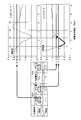
- FIG. 4 is an explanatory diagram of a method of calculating the integrated dose based on the shift amount.
- the first estimation unit 53 estimates at least one integrated dose of the V / I conversion element 28 based on the zero point current and the zero point shift data.
- the zero point current detected by the detector 20 installed at the plurality of detection points 20 at the point A is ⁇ 0.25 (%).
- the integrated irradiation amount of the detector 20 at the point A is the value of (1), (3) or (4), which is the intersection of the straight line of ⁇ 0.25 on the vertical axis and the zero point shift data in FIG. It is estimated to be.
- the first estimation unit 53 estimates the integrated dose as the value of (1), (3), or (4).
- the second estimation unit 54 estimates at least one integrated irradiation amount of the V / I conversion element 28 based on the span shift amount and the span shift data. For example, it is assumed that the span deviation amount measured by the detector 20 installed at the point A is ⁇ 1.5 (%).
- the second estimator 54 performs the same estimation procedure as the first estimator 53, and cumulatively irradiates the value of (1) or (2) that is the intersection of the straight line with a vertical axis of ⁇ 1.5 and the span shift data. Estimate with quantity.
- the comparison unit 56 compares the integrated doses estimated by the first estimating unit 53 and the second estimating unit 54, respectively, and identifies the common integrated dose as the true integrated dose. In the example of FIG. 4, since only (1) is the common estimated value among the estimated values of (1) to (4), the comparison unit 56 specifies the estimated value of (1) as the true integrated dose. . The specified true integrated dose is sent to the calculation unit 57.
- the calculation unit 57 calculates the radiation dose by dividing the true integrated dose by the period from the start of detection by the detector 20.
- the calculated radiation dose per unit time is displayed on the display unit 17 and confirmed by the operator.
- a warning unit 58 is connected to the comparison unit 56 and the display unit 17.
- the warning unit 58 gives a warning when the integrated dose specified by the calculation unit 57 is larger than a predetermined threshold value.
- the measuring device 10 is deteriorated by irradiation with radiation for a long period of time, so that accurate water level detection is not possible. Therefore, a threshold is set for the integrated dose, and a warning is displayed on the display unit 17 as a replacement time when the cumulative dose exceeds the threshold. Note that a plurality of threshold values may be set, and the warning may be changed according to the stage of the integrated dose.
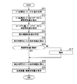
- the recording unit 51 acquires the confirmed zero point current and span deviation amount (step S11). Then, the first estimation unit 53 and the second estimation unit 54 refer to the recording unit 51 and the correlation holding unit 52, respectively.
- the first estimation unit 53 estimates at least one integrated dose of the V / I conversion element 28 based on the zero point current and the zero point shift data (first estimation step S12). In FIG. 4, the first estimation unit 53 estimates the values (1), (3), and (4) as the integrated dose. Further, the second estimation unit 54 estimates at least one integrated irradiation amount of the V / I conversion element 28 based on the recorded span deviation amount and span shift data (second estimation step S13). In FIG. 4, the second estimation unit 54 estimates the values (1) and (2) as the integrated dose.
- the comparing unit 56 compares the integrated doses estimated by the first estimating unit 53 and the second estimating unit 54, respectively, and sets the common integrated dose (1) as the true integrated dose (step S14).
- the calculation unit 57 calculates the radiation dose per unit time from the true integrated dose as shown in Equation M (step S15). The calculated radiation dose per unit time is displayed on the display unit 17 and confirmed by the operator.
- step S16: NO When the integrated dose specified by the calculation unit 57 is greater than or equal to a predetermined threshold (step S16: NO), the warning unit 58 displays a warning on the display unit 17 (step S17). Further, the radiation amount per unit time is calculated by the calculation unit 57 (step S18), and is displayed on the display unit 17 together with the integrated irradiation amount (step S19).
- step S16: YES the integrated dose specified by the calculation unit 57 is equal to or less than the predetermined threshold
- step S19: END the radiation dose per unit time and the true integrated dose are displayed on the display unit 17 without warning (step S18).
- the radiation dose at the detection point can be determined without adding a new device to the detector 20 that detects a specific physical quantity. Can do.
- the indexing device 50 can be integrated with the measuring device 10 to form a single measuring device 90 with a dose indexing function as a whole.
- a plurality of detectors 20 or measuring devices 10 may be connected to one indexing device 50 and installed at different installation locations. By sharing the indexing device 50 among the plurality of detectors 20 or the measuring devices 10, it is possible to concentrate monitoring of a plurality of detection points and management of the measuring devices 10.
- FIG. 6 is an explanatory diagram of a dose indexing method according to the second embodiment.
- the first estimation unit 53 of the indexing device 50 according to the second embodiment limits the reference range of the zero point shift data by two or more zero point currents having different recording times. Since the zero point shift data is often the result of a measurement experiment, it may have many extreme values.
- the interval is limited to [A, B] using two zero point currents one month and three months after the start of detection. Due to this limitation, (3) and (4) are excluded from the estimated integrated dose.
- the integrated integrated dose common to the integrated dose estimated by the second estimating unit 54 is set as the true integrated dose.
- FIG. 7 is explanatory drawing of the modification of the dose indexing method concerning 2nd Embodiment.
- the section limitation based on the two or more recording times described above may be performed on the span shift data in the second estimation unit 54 as shown in FIG. That is, the span shift data reference range can be limited by two or more span shift amounts having different recording times.
- the dose indexing method according to the second embodiment limits the reference range by two or more shift amounts having different recording times, so that the true integrated irradiation dose can be obtained in addition to the effects of the first embodiment. Can be specified.
- FIG. 8 is a schematic configuration diagram of a measurement apparatus 90 with a dose indexing function (hereinafter referred to as “measurement apparatus 90 with index”) according to the third embodiment.
- FIG. 9 is a figure which shows an example of the detector 20 provided with the water immersion part 61a (bubbler tube 61a) of the auxiliary
- the indexing device 50 includes an auxiliary measurement unit 61 that is fixed to the outer surface of the detector 20 and measures the water pressure P w received by the detector 20. .
- Auxiliary measuring unit 61 for example, a Baburachubu 61a to the open end 27 is fixed to the outer surface of the detector 20, measuring unit 61b for applying a back pressure P s in Baburachubu 61a for measuring the back pressure P s And consist of
- the measurement unit 61b applies the back pressure P s until a bubble comes out from the opening end 27 of the bubbler tube 61a, and measures the limit back pressure P s where the bubble comes out from the opening end 27. Then, the measured back pressure P s is transmitted to the application unit 16 and applied to the reference pressure side diaphragm 25 a via the hollow cable 23.
- the limit back pressure P s applied by the measuring unit 61b is substantially the same as the water pressure P w .
- the shift is being finely corrected in the measurement unit 61b, is fully consistent with pressure P w.
- FIG. 10 (A) is an explanatory view of a calibration method of a conventional throw-type water level gauge 10A
- FIG. 10 (B) is an explanatory view of a calibration method using the measuring apparatus 90 with index.
- a detector 20 is pulled up at a time until the water surface, the water pressure P w according to the water pressure side diaphragm 25b was made to coincide with the atmospheric pressure P atm. That is, by raising the detector 20 to the water completely, as shown in FIG. 10 (A), the water pressure P w is lowered (P w ⁇ P atm ) to check whether the indicated value indicates the zero point. It was.
- the calibration unit 12 calibrates the indicated value so that the indicated value indicates a zero point when the back pressure P s is applied to the reference pressure side diaphragm 25a.
- the back pressure P s can also be used when performing span calibration. That is, the span calibration can be performed without raising the detector 20 by applying the pressure from the applying unit 16 so that the differential pressure ⁇ P with respect to the back pressure P s becomes a predetermined value.
- the third embodiment has the same structure and operation procedure as the first embodiment except that the calibration is performed by applying the pressure to the reference pressure side diaphragm 25a based on the pressure measured by the auxiliary measuring unit 61, a duplicate description will be given. Omitted. Also in the drawings, portions having a common configuration or function are denoted by the same reference numerals, and redundant description is omitted.
- the first pressure is applied to the reference pressure side diaphragm 25a based on the back pressure P s measured by the auxiliary measuring unit 61.
- calibration can be performed without raising the detector 20.
- the indexing device 50 it is possible to determine the radiation dose at the detection point without adding a new device to the detector 20 that detects a specific physical quantity.
- the liquid whose water level is detected is described as being limited to the radioactive contamination liquid, but the present invention is not limited to the radioactive contamination liquid.
- recording unit 52 ... correlation holding unit, 53 ... first estimating unit, 54 ... second estimating unit, 56 ... Comparison part, 57 ... Dose calculation part (calculation part), 58 ... Warning part, 61 (61a, 61b) ... Auxiliary measurement part (immersion part, measurement part), 61a (61) ... Bubbler tube, 90 ... Dose ratio out function measurement device (indexing with measurement device), P atm ... the atmospheric pressure, P s Back pressure, P w ... water pressure, ⁇ P ... differential pressure.
Landscapes
- Physics & Mathematics (AREA)
- General Physics & Mathematics (AREA)
- Health & Medical Sciences (AREA)
- Life Sciences & Earth Sciences (AREA)
- High Energy & Nuclear Physics (AREA)
- Molecular Biology (AREA)
- Spectroscopy & Molecular Physics (AREA)
- Fluid Mechanics (AREA)
- Measurement Of Radiation (AREA)
- Measurement Of Levels Of Liquids Or Fluent Solid Materials (AREA)
Abstract
線量割出装置50は、物理量を電圧として検出する検出器20と、物理量を電圧から電流に変換するV/I変換素子28と、放射線の照射によって、V/I変換素子28のゼロ点電流および真値からのスパンずれ量を記録する記録部51と、予め取得した積算照射量とゼロ点電流との相関を示すゼロ点シフトデータおよび積算照射量とスパンずれ量との相関を示すスパンシフトデータを保持する相関保持部52と、記録部51に記録されたゼロ点電流およびゼロ点シフトデータに基づいてV/I変換素子28の積算照射量を少なくとも1つ推定する第1推定部53と、記録部51に記録されたスパンずれ量およびスパンシフトデータに基づいてV/I変換素子28の積算照射量を少なくとも1つ推定する第2推定部54と、第1推定部53および第2推定部54がそれぞれ推定した積算照射量を比較して共通する積算照射量を真の積算照射量として特定する比較部56と、を備える。
Description
本発明は、特定の物理量を検出する検出機器による検出地点における線量割出技術に関する。
放射線量が基準値以上であって内部への立ち入りが困難である施設において、その内部の情報の取得が求められることがある。
求められる情報は、例えば、施設内の圧力、温度または施設内に溜まった液体の水位などの物理量に関する情報である。
検出される物理量は、多くの場合、検出器に電圧の形態で検出される。
検出された電圧の伝送方式は、電圧のまま伝送する方式と、電圧からV/I変換によって電流にして伝送する方式と、に大別される。
情報を電流の形態で伝送する方式は、伝送距離が長い場合には電圧のまま伝送するよりもノイズの影響が小さいという特徴がある。
求められる情報は、例えば、施設内の圧力、温度または施設内に溜まった液体の水位などの物理量に関する情報である。
検出される物理量は、多くの場合、検出器に電圧の形態で検出される。
検出された電圧の伝送方式は、電圧のまま伝送する方式と、電圧からV/I変換によって電流にして伝送する方式と、に大別される。
情報を電流の形態で伝送する方式は、伝送距離が長い場合には電圧のまま伝送するよりもノイズの影響が小さいという特徴がある。
このような物理量を検出して測定する測定装置は、長期間の使用によって測定装置内部のばねの弾性の変化などによって表示された指示値が真値からずれてくることがある。
そこで、一般に、検出器の設置時または設置後所定の期間ごとなど特定の時期で指示値の校正をする。
そこで、一般に、検出器の設置時または設置後所定の期間ごとなど特定の時期で指示値の校正をする。
校正には、ゼロ点校正およびスパン校正の2種類が実施されることが多い。
ゼロ点校正とは、V/I変換素子への電圧の入力がゼロのときに指示値がゼロになるようにする校正のことである。
なお、V/I変換素子への電圧の入力がゼロのときにV/I変換素子から出力される電流量を、以下「ゼロ点電流」という。
ゼロ点校正とは、V/I変換素子への電圧の入力がゼロのときに指示値がゼロになるようにする校正のことである。
なお、V/I変換素子への電圧の入力がゼロのときにV/I変換素子から出力される電流量を、以下「ゼロ点電流」という。
スパン校正とは、V/I変換素子へ既知の複数の電圧を入力したときに、入力した各電圧において指示値が物理量の真値を示すようにする校正のことである。
なお、付与された既知の電圧に対して、V/I変換素子が出力する電流値の真値からのずれ量を、以下「スパンずれ量」という。
なお、付与された既知の電圧に対して、V/I変換素子が出力する電流値の真値からのずれ量を、以下「スパンずれ量」という。
立ち入りが困難な場所に設置された検出機器には、頻繁な交換および補修が困難であることから、構造が簡素で耐久性が高いことに加えて、1台でできるだけ多くの情報を取得することが求められていた。
特に、放射能汚染された施設内に設置される検出機器には、放射線量の取得の要求が高い。
放射線量の情報を取得することで、単に施設内の放射線量を把握することができるだけでなく、被ばく量に基づく検出機器の交換時期も把握することが可能になる。
特に、放射能汚染された施設内に設置される検出機器には、放射線量の取得の要求が高い。
放射線量の情報を取得することで、単に施設内の放射線量を把握することができるだけでなく、被ばく量に基づく検出機器の交換時期も把握することが可能になる。
本発明はこのような事情を考慮してなされたもので、特定の物理量を検出する検出器に新たな機器を追加することなく検出地点における放射線量を割り出すことが可能な線量割出装置、線量割出方法および線量割出機能付き測定装置を提供することを目的とする。
本実施形態にかかる線量割出装置は、検出した特定の物理量をV/I変換素子で電圧から電流に変換して伝送する測定装置に実装される線量割出装置において、放射線の照射によって、V/I変換素子が電圧の非入力時に出力するゼロ点電流および付与された既知の電圧に対して出力する電流値の真値からのずれ量を記録する記録部と、予め取得した放射線の積算照射量とゼロ点電流との相関を示すゼロ点シフトデータ、および積算照射量とずれ量との相関を示すスパンシフトデータを保持する相関保持部と、記録部に記録されたゼロ点電流およびゼロ点シフトデータに基づいてV/I変換素子の積算照射量を少なくとも1つ推定する第1推定部と、記録部に記録されたずれ量およびスパンシフトデータに基づいてV/I変換素子の積算照射量を少なくとも1つ推定する第2推定部と、第1推定部および第2推定部がそれぞれ推定した積算照射量を比較して共通する積算照射量を真の積算照射量として特定する比較部と、を備えるものである。
また、本実施形態にかかる線量割出機能付き測定装置は、特定の物理量を電圧として検出する検出器と、物理量を電圧から電流に変換するV/I変換素子と、放射線の照射によって、V/I変換素子が電圧の非入力時に出力するゼロ点電流および付与された既知の電圧に対して出力する電流値の真値からのずれ量を記録する記録部と、予め取得した放射線の積算照射量とゼロ点電流との相関を示すゼロ点シフトデータ、および積算照射量とずれ量との相関を示すスパンシフトデータを保持する相関保持部と、記録部に記録されたゼロ点電流およびゼロ点シフトデータに基づいてV/I変換素子の積算照射量を少なくとも1つ推定する第1推定部と、記録部に記録されたずれ量およびスパンシフトデータに基づいてV/I変換素子の積算照射量を少なくとも1つ推定する第2推定部と、第1推定部および第2推定部がそれぞれ推定した積算照射量を比較して共通する積算照射量を真の積算照射量として特定する比較部と、を備えるものである。
また、本実施形態にかかる線量割出方法は、検出した特定の物理量をV/I変換素子で電圧から電流に変換して伝送する測定装置を用いた線量割出方法において、放射線の照射によって、V/I変換素子が電圧の非入力時に出力するゼロ点電流および付与された既知の電圧に対して出力する電流値の真値からのずれ量を取得するステップと、予め取得した放射線の積算照射量とゼロ点電流との相関を示すゼロ点シフトデータ、および積算照射量とずれ量との相関を示すスパンシフトデータを参照するステップと、記録されたゼロ点電流およびゼロ点シフトデータに基づいてV/I変換素子の積算照射量を少なくとも1つ推定する第1推定ステップと、記録されたずれ量およびスパンシフトデータに基づいてV/I変換素子の積算照射量を少なくとも1つ推定する第2推定ステップと、第1推定ステップおよび第2推定ステップで推定したそれぞれの積算照射量を比較して共通する積算照射量を真の積算照射量とするステップと、を含むものである。
以下、本実施形態を添付図面に基づいて説明する。
〔測定装置10〕
まず、線量割出装置50(以下、単に「割出装置50」という)が適用される測定装置10について図1および図2を用いて説明する。
〔測定装置10〕
まず、線量割出装置50(以下、単に「割出装置50」という)が適用される測定装置10について図1および図2を用いて説明する。
図1は、第1実施形態にかかる割出装置50およびこの割出装置50が適用される測定装置10の概略構成図である。
割出装置50が適用される測定装置10は、その検出器20が放射能汚染された施設内などに設置される。
測定装置10は、検出器20で電圧の形態で検出した物理量を電流に変換して、電流の形態で遠隔に伝送する。
割出装置50が適用される測定装置10は、その検出器20が放射能汚染された施設内などに設置される。
測定装置10は、検出器20で電圧の形態で検出した物理量を電流に変換して、電流の形態で遠隔に伝送する。
測定装置10は、例えば自然災害の被災時に原子力発電所内に放出されて溜まった冷却液の水位を測定する投込式水位計10Aなどである。
以下の実施形態では、投込式水位計10Aを測定装置10の例にとって説明する。
ただし、放射線量の取得が求められる箇所に設けられて検出した情報を電流に変換して伝送するものであれば、投込式水位計10Aの例に限らず測定装置10になりうる。
以下の実施形態では、投込式水位計10Aを測定装置10の例にとって説明する。
ただし、放射線量の取得が求められる箇所に設けられて検出した情報を電流に変換して伝送するものであれば、投込式水位計10Aの例に限らず測定装置10になりうる。
投込式水位計10Aは、図1に示されるように、液中に投げ込まれる検出器20が、信号線13を介して変換部14に接続されている。
変換部14は、例えば中央制御室内の表示部17に接続されている。
変換部14は、検出器20から受信した液体の水位に関する電流をI/V変換して、表示部17へ送信する。
変換部14は、例えば中央制御室内の表示部17に接続されている。
変換部14は、検出器20から受信した液体の水位に関する電流をI/V変換して、表示部17へ送信する。
ここで、図2は、投込式水位計10Aが備える検出器20の概略断面図である。
検出器20は、図2に示されるように、一方の底面に入水孔24が設けられた筐体21によって、円筒状の外形を有している。
筐体21の内部には、入水孔24が設けられた底面の付近に圧力センサ22が筐体21を封止するように設置されている。
この圧力センサ22によって筐体21の内部は周囲の液体から隔離されて、圧力センサ22からさらに内部には液体は侵入しない。
検出器20は、図2に示されるように、一方の底面に入水孔24が設けられた筐体21によって、円筒状の外形を有している。
筐体21の内部には、入水孔24が設けられた底面の付近に圧力センサ22が筐体21を封止するように設置されている。
この圧力センサ22によって筐体21の内部は周囲の液体から隔離されて、圧力センサ22からさらに内部には液体は侵入しない。
一方、入水孔24が設けられていない他方の底面には、中空ケーブル23が接続されている。
中空ケーブル23は、信号線13および強化線18とともに被覆されて伝線29となって水上まで敷かれる。
中空ケーブル23は、通常時は、水上の開口部で大気開放されており、筐体21の内部を大気圧Patmに維持させている。
つまり、筐体21の内部に面する片面は大気圧Patmを受ける。
中空ケーブル23は、信号線13および強化線18とともに被覆されて伝線29となって水上まで敷かれる。
中空ケーブル23は、通常時は、水上の開口部で大気開放されており、筐体21の内部を大気圧Patmに維持させている。
つまり、筐体21の内部に面する片面は大気圧Patmを受ける。
一方、圧力センサ22のうち液体と接触する他面は水圧Pwを受ける。
圧力センサ22は、例えば、隔膜にかかる圧力を電気信号の大きさに変換するダイヤフラム25を利用したものが広く使用されている。
ダイヤフラムとは、弾性のある隔膜のことであり、圧力による隔膜の膨張およびへこみの度合いが読み取られるものである。
この度合いを電気的に読み取る方法には、ダイヤフラム25に設置された圧電素子によって歪みを感知する半導体歪ゲ-ジ式または変位を感知する静電容量式などがある。
圧力センサ22は、例えば、隔膜にかかる圧力を電気信号の大きさに変換するダイヤフラム25を利用したものが広く使用されている。
ダイヤフラムとは、弾性のある隔膜のことであり、圧力による隔膜の膨張およびへこみの度合いが読み取られるものである。
この度合いを電気的に読み取る方法には、ダイヤフラム25に設置された圧電素子によって歪みを感知する半導体歪ゲ-ジ式または変位を感知する静電容量式などがある。
圧力センサ22が有する水圧側ダイヤフラム25bが受ける水圧Pwと、基準圧側ダイヤフラム25aが中空ケーブル23を介して受ける大気圧Patmとの差圧ΔP(図10)は、電圧に変換されて差分部26に読み取られる。
なお、ダイヤフラム25の利用に代えてばね(図示せず)を利用して水圧を計測するものも検出器20として同様に動作する。
なお、ダイヤフラム25の利用に代えてばね(図示せず)を利用して水圧を計測するものも検出器20として同様に動作する。
読み取られた電圧は、V/I変換素子28で電流に変換されて、図1に示されるように、変換部14が接続される信号線13に出力される。
V/I変換素子28から送信される差圧ΔPに基づく電気信号は、変換部14で電圧に変換されて、表示部17に液体の水位として表示される。
V/I変換素子28から送信される差圧ΔPに基づく電気信号は、変換部14で電圧に変換されて、表示部17に液体の水位として表示される。
しかし、この水位の指示値は、上述のように水圧Pwなどの圧力に基づいて計算されるものであるため、実際の水位からずれることがある。
よって、所定の時期に基準圧側ダイヤフラム25a(25)に既知の圧力を印加して、指示値のゼロ点校正またはスパン校正などの校正がなされる。
印加される圧力は、例えば表示部17から印加部16に送信される作業員の指令に従って制御される。
印加部16は、三方弁19を介して中空ケーブル23に接続されている。
よって、所定の時期に基準圧側ダイヤフラム25a(25)に既知の圧力を印加して、指示値のゼロ点校正またはスパン校正などの校正がなされる。
印加される圧力は、例えば表示部17から印加部16に送信される作業員の指令に従って制御される。
印加部16は、三方弁19を介して中空ケーブル23に接続されている。
(第1実施形態)
引き続き図1を用いて、割出装置50について説明する。
第1実施形態にかかる割出装置50は、図1に示されるように、記録部51、相関保持部52、第1推定部53、第2推定部54、比較部56、算出部57(図1中、線量算出部57)および警告部58を備える。
引き続き図1を用いて、割出装置50について説明する。
第1実施形態にかかる割出装置50は、図1に示されるように、記録部51、相関保持部52、第1推定部53、第2推定部54、比較部56、算出部57(図1中、線量算出部57)および警告部58を備える。
記録部51は、ゼロ点電流およびスパンずれ量(以下、ゼロ点電流およびスパンずれ量を合わせて、「シフト量」という)を記録して蓄積する。
半導体であるV/I変換素子28に放射線が照射されると、V/I変換素子28から出力される電流が不可逆変化し、シフト量となる。
測定装置10において物理量の表示する表示機構の機械強度が十分な場合には、シフト量のうち表示機構の劣化によるものは無視することができる。
このようにシフト量を発生させる他の要素を無視または取り除くことができる場合、シフト量の発生は、放射線の照射に起因しているといえる。
そこで、記録部51は、例えば1月間隔で実施されるゼロ点校正およびスパン校正などの際に確認されたシフト量を記録して蓄積する。
半導体であるV/I変換素子28に放射線が照射されると、V/I変換素子28から出力される電流が不可逆変化し、シフト量となる。
測定装置10において物理量の表示する表示機構の機械強度が十分な場合には、シフト量のうち表示機構の劣化によるものは無視することができる。
このようにシフト量を発生させる他の要素を無視または取り除くことができる場合、シフト量の発生は、放射線の照射に起因しているといえる。
そこで、記録部51は、例えば1月間隔で実施されるゼロ点校正およびスパン校正などの際に確認されたシフト量を記録して蓄積する。
相関保持部52は、予め取得したゼロ点シフトデータおよびスパンシフトデータを保持する。
ゼロ点シフトデータとは、放射線の積算照射量とゼロ点電流との相関関係を示すデータである。
スパンシフトデータとは、放射線の積算照射量とスパンずれ量との相関関係を示すデータである。
ゼロ点シフトデータとは、放射線の積算照射量とゼロ点電流との相関関係を示すデータである。
スパンシフトデータとは、放射線の積算照射量とスパンずれ量との相関関係を示すデータである。
ここで、図3(A)はゼロ点シフトデータの一例を示す図、図3(B)はスパンシフトデータの一例を示す図である。
図3(A),(B)いずれも横軸は積算放射線量(kGy)である。
また、縦軸は、図3(A)はゼロ点電流、図3(B)はスパンずれ量である。
図3(A),(B)からわかるように、V/I変換素子28に用いられる半導体の特性として、シフト量はいずれも、積算放射線量に比例せずに変化する。
図3(A),(B)いずれも横軸は積算放射線量(kGy)である。
また、縦軸は、図3(A)はゼロ点電流、図3(B)はスパンずれ量である。
図3(A),(B)からわかるように、V/I変換素子28に用いられる半導体の特性として、シフト量はいずれも、積算放射線量に比例せずに変化する。
例えば、ゼロ点電流(相対値)の絶対値は、2kGy程度までは積算放射線量に伴って増加するが、2kGy程度を超えると、減少してゼロに近づく。
その後も、ゼロ点電流の絶対値は、いくつかの極値を有して変化する。
相関保持部52は、実際に用いられる半導体と同類の半導体について予め測定実験などによって取得したゼロ点シフトデータおよびスパンシフトデータを保持する。
なお、ゼロ点シフトデータおよびスパンシフトデータは、グラフデータではなく数値データであってもよい。
その後も、ゼロ点電流の絶対値は、いくつかの極値を有して変化する。
相関保持部52は、実際に用いられる半導体と同類の半導体について予め測定実験などによって取得したゼロ点シフトデータおよびスパンシフトデータを保持する。
なお、ゼロ点シフトデータおよびスパンシフトデータは、グラフデータではなく数値データであってもよい。
記録部51および相関保持部52には、それぞれ第1推定部53および第2推定部54が接続される。
ここで、図4は、シフト量に基づく積算照射量の算出方法の説明図である。
第1推定部53は、ゼロ点電流およびゼロ点シフトデータに基づいてV/I変換素子28の積算照射量を少なくとも1つ推定する。
ここで、図4は、シフト量に基づく積算照射量の算出方法の説明図である。
第1推定部53は、ゼロ点電流およびゼロ点シフトデータに基づいてV/I変換素子28の積算照射量を少なくとも1つ推定する。
例えば図4に示されるように、複数の検出地点に設置された複数の検出器20のうちA地点に設置されたものが検出したゼロ点電流が、-0.25(%)であったとする。
この場合A地点の検出器20の積算照射量は、図4において縦軸が-0.25の直線と、ゼロ点シフトデータとの交点である(1)、(3)または(4)の値と推定される。
このような手順で、第1推定部53は、積算照射量を(1)、(3)または(4)の値と推定する。
この場合A地点の検出器20の積算照射量は、図4において縦軸が-0.25の直線と、ゼロ点シフトデータとの交点である(1)、(3)または(4)の値と推定される。
このような手順で、第1推定部53は、積算照射量を(1)、(3)または(4)の値と推定する。
第2推定部54は、スパンずれ量およびスパンシフトデータに基づいてV/I変換素子28の積算照射量を少なくとも1つ推定する。
例えば、A地点に設置された検出器20で計測されたスパンずれ量が、-1.5(%)であったとする。
第2推定部54は、第1推定部53と同様の推定手順で、縦軸が-1.5の直線と、スパンシフトデータとの交点である(1)または(2)の値を積算照射量と推定する。
例えば、A地点に設置された検出器20で計測されたスパンずれ量が、-1.5(%)であったとする。
第2推定部54は、第1推定部53と同様の推定手順で、縦軸が-1.5の直線と、スパンシフトデータとの交点である(1)または(2)の値を積算照射量と推定する。
比較部56は、第1推定部53および第2推定部54がそれぞれ推定した積算照射量を比較して、共通する積算照射量を真の積算照射量として特定する。
図4の例では、(1)~(4)の推定値のうち(1)のみが共通の推定値であるので、比較部56は(1)の推定値を真の積算照射量として特定する。
特定された真の積算照射量は、算出部57に送られる。
図4の例では、(1)~(4)の推定値のうち(1)のみが共通の推定値であるので、比較部56は(1)の推定値を真の積算照射量として特定する。
特定された真の積算照射量は、算出部57に送られる。
算出部57は、真の積算照射量を検出器20の検出開始からの期間で除算して放射線量を算出する。
図4の例では、真の積算照射量は1.2kGyである。
よって、検出開始からの期間が3カ月であるとすると、単位時間当たりの放射線量は、次式Mで算出される。
1.2kGy/(3カ月×30日×24時間)=0.55Gy/h (M)
算出された単位時間当たりの放射線量は、表示部17に表示されて運転員に確認される。
図4の例では、真の積算照射量は1.2kGyである。
よって、検出開始からの期間が3カ月であるとすると、単位時間当たりの放射線量は、次式Mで算出される。
1.2kGy/(3カ月×30日×24時間)=0.55Gy/h (M)
算出された単位時間当たりの放射線量は、表示部17に表示されて運転員に確認される。
また、比較部56および表示部17には、警告部58が接続される。
警告部58は、算出部57で特定した積算照射量が既定の閾値より大きい場合に警告をする。
測定装置10は、長期間の放射線の照射によって劣化して、正確な水位の検出ができなくなる。
そこで、積算照射量に閾値を設定して、積算照射量がこの閾値以上になったときを交換時期として表示部17に警告を表示する。
なお、閾値を複数設定して、積算照射量の段階に合わせて警告を変化させてもよい。
警告部58は、算出部57で特定した積算照射量が既定の閾値より大きい場合に警告をする。
測定装置10は、長期間の放射線の照射によって劣化して、正確な水位の検出ができなくなる。
そこで、積算照射量に閾値を設定して、積算照射量がこの閾値以上になったときを交換時期として表示部17に警告を表示する。
なお、閾値を複数設定して、積算照射量の段階に合わせて警告を変化させてもよい。
次に、第1実施形態にかかる線量割出方法を、図5のフローチャートを用いて説明する(適宜、図1および図4を参照)。
まず、ゼロ点校正およびスパン校正などの際に、記録部51が、確認されたゼロ点電流およびスパンずれ量を取得する(ステップS11)。
そして、第1推定部53および第2推定部54が、それぞれ記録部51および相関保持部52を参照する。
そして、第1推定部53および第2推定部54が、それぞれ記録部51および相関保持部52を参照する。
第1推定部53は、ゼロ点電流およびゼロ点シフトデータに基づいて、V/I変換素子28の積算照射量を少なくとも1つ推定する(第1推定ステップS12)。
第1推定部53は、図4においては(1)、(3)および(4)の値を積算照射量として推定する。
また、第2推定部54は、記録されたスパンずれ量およびスパンシフトデータに基づいて、V/I変換素子28の積算照射量を少なくとも1つ推定する(第2推定ステップS13)。
第2推定部54は、図4においては(1)および(2)の値を積算照射量として推定する。
第1推定部53は、図4においては(1)、(3)および(4)の値を積算照射量として推定する。
また、第2推定部54は、記録されたスパンずれ量およびスパンシフトデータに基づいて、V/I変換素子28の積算照射量を少なくとも1つ推定する(第2推定ステップS13)。
第2推定部54は、図4においては(1)および(2)の値を積算照射量として推定する。
そして、比較部56が、第1推定部53および第2推定部54がそれぞれ推定した積算照射量を比較して、共通する積算照射量(1)を真の積算照射量とする(ステップS14)。
さらに、算出部57が、真の積算照射量から式Mのように単位時間当たりの放射線量を算出する(ステップS15)。
算出された単位時間当たりの放射線量は、表示部17に表示されて運転員に確認される。
さらに、算出部57が、真の積算照射量から式Mのように単位時間当たりの放射線量を算出する(ステップS15)。
算出された単位時間当たりの放射線量は、表示部17に表示されて運転員に確認される。
算出部57で特定した積算照射量が既定の閾値以上の場合(ステップS16:NO)、警告部58は表示部17に警告を表示する(ステップS17)。
また、算出部57で単位時間あたりの放射線量を算出して(ステップS18)、積算照射量とともに表示部17に表示する(ステップS19)。
算出部57で特定した積算照射量が既定の閾値以下の場合(ステップS16:YES)、警告はせずに単位時間あたりの放射線量および真の積算照射線量を表示部17に表示する(ステップS18,ステップS19:END)。
また、算出部57で単位時間あたりの放射線量を算出して(ステップS18)、積算照射量とともに表示部17に表示する(ステップS19)。
算出部57で特定した積算照射量が既定の閾値以下の場合(ステップS16:YES)、警告はせずに単位時間あたりの放射線量および真の積算照射線量を表示部17に表示する(ステップS18,ステップS19:END)。
以上のように、第1実施形態にかかる割出装置50および線量割出方法によれば、特定の物理量を検出する検出器20に新たな機器を追加することなく検出地点における放射線量を割り出すことができる。
なお、割出装置50を測定装置10に一体化させて全体として1つの線量割出機能付き測定装置90とすることもできる。
また、例えば、1つの割出装置50に対して複数の検出器20または測定装置10を接続して、それぞれ異なる設置箇所に設置してもよい。
複数の検出器20または測定装置10が割出装置50を共有することで、複数の検出地点の監視および測定装置10の管理を一極に集中させることができる。
複数の検出器20または測定装置10が割出装置50を共有することで、複数の検出地点の監視および測定装置10の管理を一極に集中させることができる。
(第2実施形態)
図6は、第2実施形態にかかる線量割出方法の説明図である。
第2実施形態にかかる割出装置50の第1推定部53は、図6に示されるように、記録時刻の異なる2以上のゼロ点電流によってゼロ点シフトデータの参照範囲を限定する。
ゼロ点シフトデータは測定実験の結果であることが多いので、多数の極値を有していることがある。
図6は、第2実施形態にかかる線量割出方法の説明図である。
第2実施形態にかかる割出装置50の第1推定部53は、図6に示されるように、記録時刻の異なる2以上のゼロ点電流によってゼロ点シフトデータの参照範囲を限定する。
ゼロ点シフトデータは測定実験の結果であることが多いので、多数の極値を有していることがある。
よって、1つのゼロ点電流に対して多数の積算照射線量が推定されてしまい、スパンずれ量と組み合わせても真の積算照射線量が1つに特定されないことがある。
そこで、例えば図6に示されるように、検出開始から1カ月後および3カ月後の2つのゼロ点電流を用いて、区間を[A、B]に限定する。
この限定によって、(3)および(4)は積算照射量の推定値から除外されることになる。
そこで、例えば図6に示されるように、検出開始から1カ月後および3カ月後の2つのゼロ点電流を用いて、区間を[A、B]に限定する。
この限定によって、(3)および(4)は積算照射量の推定値から除外されることになる。
そして、第1実施形態と同様に、第2推定部54で推定した積算照射量とで共通な積算照射量を真の積算照射量とする。
また、図7は第2実施形態にかかる線量割出方法の変形例の説明図である。
上述の2以上の記録時刻に基づく区間の限定は、図7に示されるように、第2推定部54においてスパンシフトデータについて実施してもよい。
つまり、記録時刻の異なる2以上のスパンずれ量によってスパンシフトデータの参照範囲を限定することもできる。
また、図7は第2実施形態にかかる線量割出方法の変形例の説明図である。
上述の2以上の記録時刻に基づく区間の限定は、図7に示されるように、第2推定部54においてスパンシフトデータについて実施してもよい。
つまり、記録時刻の異なる2以上のスパンずれ量によってスパンシフトデータの参照範囲を限定することもできる。
なお、第1推定部53または第2推定部54の参照範囲を限定すること以外は、第2実施形態は第1実施形態と同じ構造および動作手順となるので、重複する説明を省略する。
図面においても、共通の構成または機能を有する部分は同一符号で示し、重複する説明を省略する。
図面においても、共通の構成または機能を有する部分は同一符号で示し、重複する説明を省略する。
以上のように、第2実施形態にかかる線量割出方法は、記録時刻の異なる2以上のシフト量によって参照範囲を限定することで、第1実施形態の効果に加えて、真の積算照射線量を特定することができる。
(第3実施形態)
図8は、第3実施形態にかかる線量割出機能付き測定装置90(以下、「割出付き測定装置90」という)の概略構成図である。
また、図9は、第3実施形態にかかる割出付き測定装置90が備える補助測定部61の浸水部61a(バブラチューブ61a)が設けられた検出器20の一例を示す図である。
図8は、第3実施形態にかかる線量割出機能付き測定装置90(以下、「割出付き測定装置90」という)の概略構成図である。
また、図9は、第3実施形態にかかる割出付き測定装置90が備える補助測定部61の浸水部61a(バブラチューブ61a)が設けられた検出器20の一例を示す図である。
第3実施形態にかかる割出装置50は、図8および図9に示されるように、検出器20の外表面に固定されて検出器20が受ける水圧Pwを測定する補助測定部61を備える。
補助測定部61は、例えば、検出器20の外表面に開口端27が固定されたバブラチューブ61aと、バブラチューブ61aに背圧Psを印加してこの背圧Psを測定する計測部61bと、からなる。
計測部61bは、バブラチューブ61aの開口端27からバブルが出るまで背圧Psを印加して、この開口端27からバブルが出る限界の背圧Psを計測する。
そして、計測した背圧Psを印加部16に送信して、中空ケーブル23を介して基準圧側ダイヤフラム25aへ印加させる。
そして、計測した背圧Psを印加部16に送信して、中空ケーブル23を介して基準圧側ダイヤフラム25aへ印加させる。
開口端27は検出器20の外表面に固定されていることから、計測部61bによって印加される限界の背圧Psは、水圧Pwとほぼ同一となる。
なお、例えば開口端27と水圧側ダイヤフラム25bとの深度にずれがある場合、このずれは、計測部61bにおいて微修正されて、水圧Pwと完全に一致される。
なお、例えば開口端27と水圧側ダイヤフラム25bとの深度にずれがある場合、このずれは、計測部61bにおいて微修正されて、水圧Pwと完全に一致される。
ここで、図10(A)は従来の投込式水位計10Aの校正方法の説明図、図10(B)は割出付き測定装置90を用いた校正方法の説明図である。
従来では、表示部17の水位の指示値を校正する場合、検出器20を一度水面まで引き上げて、水圧側ダイヤフラム25bにかかる水圧Pwを大気圧Patmと一致させていた。
つまり、検出器20を完全に水上まで引き上げることで、図10(A)に示されるように、水圧Pwを降下させて(Pw→Patm)、指示値がゼロ点を示すか確認していた。
従来では、表示部17の水位の指示値を校正する場合、検出器20を一度水面まで引き上げて、水圧側ダイヤフラム25bにかかる水圧Pwを大気圧Patmと一致させていた。
つまり、検出器20を完全に水上まで引き上げることで、図10(A)に示されるように、水圧Pwを降下させて(Pw→Patm)、指示値がゼロ点を示すか確認していた。
一方、第1実施形態にかかる校正方法では、検出器20を引き上げる代わりに、基準圧側ダイヤフラム25aに上述の背圧Psを印加して基準圧を変化させる。
つまり、図10(B)に示されるように、基準圧側ダイヤフラム25aにかかる圧力を上昇させて(Patm→Ps)、基準圧側ダイヤフラム25aの圧力を水圧Pwに一致させる。
つまり、図10(B)に示されるように、基準圧側ダイヤフラム25aにかかる圧力を上昇させて(Patm→Ps)、基準圧側ダイヤフラム25aの圧力を水圧Pwに一致させる。
校正部12は、背圧Psを基準圧側ダイヤフラム25aに印加したときに指示値がゼロ点を示すように指示値を校正する。
また、スパン校正をする際にも、この背圧Psを利用することができる。
すなわち、この背圧Psとの差圧ΔPが既定の値となるように印加部16から圧力を印加することで、検出器20を引き上げることなくスパン校正をすることができる。
また、スパン校正をする際にも、この背圧Psを利用することができる。
すなわち、この背圧Psとの差圧ΔPが既定の値となるように印加部16から圧力を印加することで、検出器20を引き上げることなくスパン校正をすることができる。
なお、補助測定部61で測定した圧力に基づいて基準圧側ダイヤフラム25aに印加して校正すること以外は、第3実施形態は第1実施形態と同じ構造および動作手順となるので、重複する説明を省略する。
図面においても、共通の構成または機能を有する部分は同一符号で示し、重複する説明を省略する。
図面においても、共通の構成または機能を有する部分は同一符号で示し、重複する説明を省略する。
以上のように、第3実施形態にかかる割出付き測定装置90によれば、補助測定部61で測定された背圧Psに基づいて基準圧側ダイヤフラム25aに圧力を印加することで、第1実施形態の効果に加えて、検出器20を引き上げることなく校正をすることができる。
以上述べた少なくとも1つの実施形態にかかる割出装置50などによれば、特定の物理量を検出する検出器20に新たな機器を追加することなく検出地点における放射線量を割り出すことができる。
本発明のいくつかの実施形態を説明したが、これらの実施形態は、例として提示したものであり、発明の範囲を限定することは意図していない。
これら実施形態は、その他の様々な形態で実施されることが可能であり、発明の要旨を逸脱しない範囲で、種々の省略、置き換え、変更、組み合わせを行うことができる。
これら実施形態やその変形は、発明の範囲や要旨に含まれると同様に、特許請求の範囲に記載された発明とその均等の範囲に含まれるものである。
これら実施形態は、その他の様々な形態で実施されることが可能であり、発明の要旨を逸脱しない範囲で、種々の省略、置き換え、変更、組み合わせを行うことができる。
これら実施形態やその変形は、発明の範囲や要旨に含まれると同様に、特許請求の範囲に記載された発明とその均等の範囲に含まれるものである。
例えば、各実施形態では水位が検出される液体を放射能汚染液体に限定して説明したが、本発明は、対象が放射能汚染液体に限定されない。
10…測定装置(投込式水位計)、12…校正部、13…信号線、14…変換部、16…印加部、17…表示部、18…強化線、19…三方弁、20…検出器、21…筐体、22…圧力センサ、23…中空ケーブル、24…入水孔、25(25a,25b)…ダイヤフラム(基準圧側ダイヤフラム,水圧側ダイヤフラム)、26…差分部、27…開口端、28…V/I変換素子、29…伝線、50…線量割出装置(割出装置)、51…記録部、52…相関保持部、53…第1推定部、54…第2推定部、56…比較部、57…線量算出部(算出部)、58…警告部、61(61a,61b)…補助測定部(浸水部,計測部)、61a(61)…バブラチューブ、90…線量割出機能付き測定装置(割出付き測定装置)、Patm…大気圧、Ps…背圧、Pw…水圧、ΔP…差圧。
Claims (11)
- 検出した特定の物理量をV/I変換素子で電圧から電流に変換して伝送する測定装置に実装される線量割出装置において、
放射線の照射によって、前記V/I変換素子が前記電圧の非入力時に出力するゼロ点電流および付与された既知の電圧に対して出力する電流値の真値からのずれ量を記録する記録部と、
予め取得した前記放射線の積算照射量と前記ゼロ点電流との相関を示すゼロ点シフトデータ、および前記積算照射量と前記ずれ量との相関を示すスパンシフトデータを保持する相関保持部と、
前記記録部に記録された前記ゼロ点電流および前記ゼロ点シフトデータに基づいて前記V/I変換素子の積算照射量を少なくとも1つ推定する第1推定部と、
前記記録部に記録された前記ずれ量および前記スパンシフトデータに基づいて前記V/I変換素子の積算照射量を少なくとも1つ推定する第2推定部と、
前記第1推定部および前記第2推定部がそれぞれ推定した前記積算照射量を比較して共通する積算照射量を真の積算照射量として特定する比較部と、を備えることを特徴とする線量割出装置。 - 前記真の積算照射量を検出開始からの期間で除算して放射線量を算出する算出部を備える請求項1に記載の線量割出装置。
- 記録時刻の異なる2以上の前記ゼロ点電流によって前記ゼロ点シフトデータの参照範囲を限定する請求項1に記載の線量割出装置。
- 記録時刻の異なる2以上の前記ずれ量によって前記スパンシフトデータの参照範囲を限定する請求項1に記載の線量割出装置。
- 特定した前記真の積算照射量が既定の閾値より大きくなった場合に警告をする警告部を備える請求項1に記載の線量割出装置。
- 特定の物理量を電圧として検出する検出器と、
前記物理量を前記電圧から電流に変換するV/I変換素子と、
放射線の照射によって、前記V/I変換素子が前記電圧の非入力時に出力するゼロ点電流および付与された既知の電圧に対して出力する電流値の真値からのずれ量を記録する記録部と、
予め取得した前記放射線の積算照射量と前記ゼロ点電流との相関を示すゼロ点シフトデータ、および前記積算照射量と前記ずれ量との相関を示すスパンシフトデータを保持する相関保持部と、
前記記録部に記録された前記ゼロ点電流および前記ゼロ点シフトデータに基づいて前記V/I変換素子の積算照射量を少なくとも1つ推定する第1推定部と、
前記記録部に記録された前記ずれ量および前記スパンシフトデータに基づいて前記V/I変換素子の積算照射量を少なくとも1つ推定する第2推定部と、
前記第1推定部および前記第2推定部がそれぞれ推定した前記積算照射量を比較して共通する積算照射量を真の積算照射量として特定する比較部と、を備えることを特徴とする線量割出機能付き測定装置。 - 前記検出器は、ダイヤフラム式圧力検出器またはばね式圧力検出器である請求項6に記載の線量割出機能付き測定装置。
- 前記検出器は複数設けられてそれぞれ異なる設置箇所に設置される請求項6に記載の線量割出機能付き測定装置。
- 前記測定装置は、投込式水圧計である請求項6に記載の線量割出機能付き測定装置。
- 前記検出器は、一部が液体中に開放された筐体の内部を圧力センサで封止して、前記圧力センサが液体から受ける水圧と前記筐体に接続された中空ケーブルによって前記内部から受ける大気圧との差圧を検出し、
前記検出器の外表面に固定されて前記検出器が受ける前記水圧を計測する計測部と、
前記計測部で計測された計測水圧を前記中空ケーブルから印加する印加部と、を備える請求項6に記載の線量割出機能付き測定装置。 - 検出した特定の物理量をV/I変換素子で電圧から電流に変換して伝送する測定装置を用いた線量割出方法において、
放射線の照射によって、前記V/I変換素子が前記電圧の非入力時に出力するゼロ点電流および付与された既知の電圧に対して出力する電流値の真値からのずれ量を取得するステップと、
予め取得した前記放射線の積算照射量と前記ゼロ点電流との相関を示すゼロ点シフトデータ、および前記積算照射量と前記ずれ量との相関を示すスパンシフトデータを参照するステップと、
記録された前記ゼロ点電流および前記ゼロ点シフトデータに基づいて前記V/I変換素子の積算照射量を少なくとも1つ推定する第1推定ステップと、
記録された前記ずれ量および前記スパンシフトデータに基づいて前記V/I変換素子の積算照射量を少なくとも1つ推定する第2推定ステップと、
前記第1推定ステップおよび前記第2推定ステップで推定したそれぞれの積算照射量を比較して共通する積算照射量を真の積算照射量とするステップと、を含むことを特徴とする線量割出方法。
Priority Applications (1)
| Application Number | Priority Date | Filing Date | Title |
|---|---|---|---|
| US15/780,683 US10527737B2 (en) | 2015-12-01 | 2016-11-30 | Dose calculation device, dose calculation method, and measurement device with dose calculation function |
Applications Claiming Priority (2)
| Application Number | Priority Date | Filing Date | Title |
|---|---|---|---|
| JP2015234894A JP6580966B2 (ja) | 2015-12-01 | 2015-12-01 | 線量割出装置、線量割出方法、線量割出プログラムおよび線量割出機能付き測定装置 |
| JP2015-234894 | 2015-12-01 |
Publications (1)
| Publication Number | Publication Date |
|---|---|
| WO2017094773A1 true WO2017094773A1 (ja) | 2017-06-08 |
Family
ID=58796986
Family Applications (1)
| Application Number | Title | Priority Date | Filing Date |
|---|---|---|---|
| PCT/JP2016/085546 Ceased WO2017094773A1 (ja) | 2015-12-01 | 2016-11-30 | 線量割出装置、線量割出方法および線量割出機能付き測定装置 |
Country Status (3)
| Country | Link |
|---|---|
| US (1) | US10527737B2 (ja) |
| JP (1) | JP6580966B2 (ja) |
| WO (1) | WO2017094773A1 (ja) |
Families Citing this family (1)
| Publication number | Priority date | Publication date | Assignee | Title |
|---|---|---|---|---|
| CN112473024B (zh) * | 2020-11-30 | 2021-09-14 | 南京航空航天大学 | 一种对bnct过程中的三维硼剂量或硼浓度进行实时监测的方法 |
Citations (2)
| Publication number | Priority date | Publication date | Assignee | Title |
|---|---|---|---|---|
| JPS63279191A (ja) * | 1987-05-12 | 1988-11-16 | Matsushita Electric Ind Co Ltd | 放射線線量測定素子 |
| JP2011137770A (ja) * | 2009-12-29 | 2011-07-14 | Hitachi Ltd | 放射線被曝量計測機能付プロセス計測機器 |
Family Cites Families (16)
| Publication number | Priority date | Publication date | Assignee | Title |
|---|---|---|---|---|
| JPS59191622A (ja) | 1983-04-15 | 1984-10-30 | Hitachi Ltd | 温度制御装置 |
| US4605859A (en) * | 1983-12-19 | 1986-08-12 | Nuclear Research Corp. | Radiation measuring apparatus |
| JP2745780B2 (ja) | 1990-05-29 | 1998-04-28 | 富士電機株式会社 | 超電導磁石 |
| JP3182807B2 (ja) | 1991-09-20 | 2001-07-03 | 株式会社日立製作所 | 多機能流体計測伝送装置及びそれを用いた流体量計測制御システム |
| JP3074895B2 (ja) | 1992-02-13 | 2000-08-07 | 株式会社島津製作所 | 圧力・差圧伝送器 |
| JPH0712941A (ja) | 1993-06-29 | 1995-01-17 | Toshiba Corp | 放射線測定装置 |
| JP2946011B2 (ja) | 1993-08-19 | 1999-09-06 | 新明和工業株式会社 | 水位制御装置 |
| JPH09243767A (ja) * | 1996-03-13 | 1997-09-19 | Toshiba Corp | 核融合炉用磁場検出器 |
| JPH1131289A (ja) * | 1997-07-10 | 1999-02-02 | Kansai Electric Power Co Inc:The | 伝送器 |
| US8974386B2 (en) * | 1998-04-30 | 2015-03-10 | Abbott Diabetes Care Inc. | Analyte monitoring device and methods of use |
| JP2000337945A (ja) | 1999-03-23 | 2000-12-08 | Hitachi Ltd | 汚水用投込式水位計 |
| JP2010219226A (ja) | 2009-03-16 | 2010-09-30 | Kobe Steel Ltd | 巻枠、巻枠の製造方法、超電導コイルの製造方法 |
| JP5259487B2 (ja) | 2009-05-15 | 2013-08-07 | 株式会社東芝 | 超電導コイル |
| JP5722195B2 (ja) | 2011-11-11 | 2015-05-20 | 株式会社東芝 | 水位検出システム及び方法 |
| JP2015041808A (ja) * | 2013-08-20 | 2015-03-02 | 株式会社東芝 | アナログ信号処理装置 |
| JP6325391B2 (ja) | 2014-08-08 | 2018-05-16 | 株式会社東芝 | 投込式水位計の調節システム、その調節方法、その調節プログラムおよび調節機能付き投込式水位計 |
-
2015
- 2015-12-01 JP JP2015234894A patent/JP6580966B2/ja active Active
-
2016
- 2016-11-30 WO PCT/JP2016/085546 patent/WO2017094773A1/ja not_active Ceased
- 2016-11-30 US US15/780,683 patent/US10527737B2/en active Active
Patent Citations (2)
| Publication number | Priority date | Publication date | Assignee | Title |
|---|---|---|---|---|
| JPS63279191A (ja) * | 1987-05-12 | 1988-11-16 | Matsushita Electric Ind Co Ltd | 放射線線量測定素子 |
| JP2011137770A (ja) * | 2009-12-29 | 2011-07-14 | Hitachi Ltd | 放射線被曝量計測機能付プロセス計測機器 |
Also Published As
| Publication number | Publication date |
|---|---|
| US20180356535A1 (en) | 2018-12-13 |
| JP2017102003A (ja) | 2017-06-08 |
| JP6580966B2 (ja) | 2019-09-25 |
| US10527737B2 (en) | 2020-01-07 |
Similar Documents
| Publication | Publication Date | Title |
|---|---|---|
| CN101706294B (zh) | 一种自动判断传感器的校准时间的方法 | |
| JP6039087B2 (ja) | プロセス変数測定ノイズ診断 | |
| CN101517377A (zh) | 带有校验的磁流量计 | |
| WO2009063218A3 (en) | Pipeline condition detecting method and apparatus | |
| CN105339776B (zh) | 用于振动仪表的仪表传感器的检验 | |
| JP2017026559A (ja) | ガスリーク検知装置およびガスリーク検知方法 | |
| JP6426371B2 (ja) | 投込式水位計の校正システム、その校正方法、および校正機能付き投込式水位計 | |
| US10067105B2 (en) | Method for operating a measuring site | |
| CN105572191A (zh) | 一种电化学气体传感器的压力补偿方法 | |
| Hashemian et al. | Nuclear plant temperature instrumentation | |
| JP6580966B2 (ja) | 線量割出装置、線量割出方法、線量割出プログラムおよび線量割出機能付き測定装置 | |
| TW201411091A (zh) | X線厚度計 | |
| CN109997030A (zh) | 用于确定检测器单元的剩余运行时段的方法 | |
| EP2579052A1 (en) | Method for measuring resistance value of conversion resistance of current mode analog /digital converter | |
| CN103256999B (zh) | 分布式光纤测温方法 | |
| CN100567060C (zh) | 一种提高调制探头测温精度的方法 | |
| Hashemian et al. | Pressure transmitter accuracy | |
| JP2015206664A (ja) | 投込式水位計の校正システム、その校正方法、その校正プログラムおよび校正機能付き投込式水位計 | |
| CN115183805B (zh) | 基于人工智能的仪器自动化计量检定方法及系统 | |
| CN102735269A (zh) | 校正方法及装置 | |
| JP6486758B2 (ja) | 投込式水位計の調節システム、その調節方法、その調節プログラムおよび調節機能付き投込式水位計 | |
| JP6325391B2 (ja) | 投込式水位計の調節システム、その調節方法、その調節プログラムおよび調節機能付き投込式水位計 | |
| JP3556409B2 (ja) | 原子炉出力測定装置 | |
| GB2460484A (en) | Pipeline condition detecting method and apparatus | |
| JP2007225507A (ja) | 放射能検査方法および装置 |
Legal Events
| Date | Code | Title | Description |
|---|---|---|---|
| 121 | Ep: the epo has been informed by wipo that ep was designated in this application |
Ref document number: 16870710 Country of ref document: EP Kind code of ref document: A1 |
|
| NENP | Non-entry into the national phase |
Ref country code: DE |
|
| 32PN | Ep: public notification in the ep bulletin as address of the adressee cannot be established |
Free format text: NOTING OF LOSS OF RIGHTS PURSUANT TO RULE 112(1) EPC (EPO FORM 1205A DATED 07.08.2018) |
|
| 122 | Ep: pct application non-entry in european phase |
Ref document number: 16870710 Country of ref document: EP Kind code of ref document: A1 |