WO2017094639A1 - ベーン型圧縮機 - Google Patents
ベーン型圧縮機 Download PDFInfo
- Publication number
- WO2017094639A1 WO2017094639A1 PCT/JP2016/085105 JP2016085105W WO2017094639A1 WO 2017094639 A1 WO2017094639 A1 WO 2017094639A1 JP 2016085105 W JP2016085105 W JP 2016085105W WO 2017094639 A1 WO2017094639 A1 WO 2017094639A1
- Authority
- WO
- WIPO (PCT)
- Prior art keywords
- rotor
- drive shaft
- vane
- forming portion
- housing
- Prior art date
- Legal status (The legal status is an assumption and is not a legal conclusion. Google has not performed a legal analysis and makes no representation as to the accuracy of the status listed.)
- Ceased
Links
Images



Classifications
-
- F—MECHANICAL ENGINEERING; LIGHTING; HEATING; WEAPONS; BLASTING
- F04—POSITIVE - DISPLACEMENT MACHINES FOR LIQUIDS; PUMPS FOR LIQUIDS OR ELASTIC FLUIDS
- F04C—ROTARY-PISTON, OR OSCILLATING-PISTON, POSITIVE-DISPLACEMENT MACHINES FOR LIQUIDS; ROTARY-PISTON, OR OSCILLATING-PISTON, POSITIVE-DISPLACEMENT PUMPS
- F04C18/00—Rotary-piston pumps specially adapted for elastic fluids
- F04C18/30—Rotary-piston pumps specially adapted for elastic fluids having the characteristics covered by two or more of groups F04C18/02, F04C18/08, F04C18/22, F04C18/24, F04C18/48, or having the characteristics covered by one of these groups together with some other type of movement between co-operating members
- F04C18/34—Rotary-piston pumps specially adapted for elastic fluids having the characteristics covered by two or more of groups F04C18/02, F04C18/08, F04C18/22, F04C18/24, F04C18/48, or having the characteristics covered by one of these groups together with some other type of movement between co-operating members having the movement defined in group F04C18/08 or F04C18/22 and relative reciprocation between the co-operating members
- F04C18/344—Rotary-piston pumps specially adapted for elastic fluids having the characteristics covered by two or more of groups F04C18/02, F04C18/08, F04C18/22, F04C18/24, F04C18/48, or having the characteristics covered by one of these groups together with some other type of movement between co-operating members having the movement defined in group F04C18/08 or F04C18/22 and relative reciprocation between the co-operating members with vanes reciprocating with respect to the inner member
-
- F—MECHANICAL ENGINEERING; LIGHTING; HEATING; WEAPONS; BLASTING
- F04—POSITIVE - DISPLACEMENT MACHINES FOR LIQUIDS; PUMPS FOR LIQUIDS OR ELASTIC FLUIDS
- F04C—ROTARY-PISTON, OR OSCILLATING-PISTON, POSITIVE-DISPLACEMENT MACHINES FOR LIQUIDS; ROTARY-PISTON, OR OSCILLATING-PISTON, POSITIVE-DISPLACEMENT PUMPS
- F04C29/00—Component parts, details or accessories of pumps or pumping installations, not provided for in groups F04C18/00 - F04C28/00
Definitions
- the present invention relates to a vane type compressor, and more particularly to a vane type compressor provided with a mechanism for preventing a drive shaft from being displaced in an axial direction with respect to a rotor due to liquid compression at start-up.
- the vane compressor includes a housing 5 that forms a low-pressure space and a high-pressure space, and a cylinder forming portion 12 that forms a cam surface 11 and forms a part of the housing 5.
- the cylinder forming part 12 is closed at both ends in the axial direction, and a pair of side block forming parts 13 and 21 constituting a part of the housing 5, and the pair of side block forming parts 13 and 21 via bearings 14 and 24.
- the drive shaft 2 protrudes from the housing 5 (second side block forming portion 21) to the outside in order to transmit rotational power from the outside.
- the drive shaft 2 protrudes from the housing 5 of the drive shaft 2.
- the clutch plate 35 of the electromagnetic clutch 32 that is opposed to the pulley 31 rotatably provided on the boss portion 23 of the housing 5 with a predetermined gap is fixed to the front end portion.
- the rotor 3 is firmly fixed to the outer peripheral surface of the drive shaft 2 by shrink fitting or the like.
- the frictional force between the rotor 3 and the drive shaft 2 becomes a dynamic frictional force that is smaller than the maximum static frictional force. That is, when the rotor 3 and the drive shaft 2 slip relative to each other in the circumferential direction, the frictional force between the rotor 3 and the drive shaft 2 decreases.
- the high pressure in the compression chamber 41 during liquid compression is driven through the clearance between the rotor 3 and the side block forming portion 13 and the clearance between the bearing 14 and the drive shaft 2 or the side block forming portion 13.
- the pressure sneaks behind the shaft 2 and the sneak pressure acts on the rear end of the drive shaft 2.
- the frictional force between the rotor 3 and the drive shaft 2 is reduced.
- the drive shaft 2 not only slip in the circumferential direction, but also the drive shaft 2 is urged toward the front end side by the high pressure acting on the rear end of the drive shaft 2 and moves in the axial direction with respect to the rotor 3. Phenomenon occurs.
- the present invention has been made in view of such circumstances, and even if the rotor and the drive shaft slip relative to each other in the circumferential direction due to liquid compression, the axial direction of the drive shaft relative to the rotor can be reduced with a simple configuration.
- the main object is to provide a vane type compressor capable of regulating movement.
- a vane type compressor includes a housing, a cylinder forming portion that forms a cam surface, and that forms part of the housing, and both ends of the cylinder forming portion in the axial direction.
- a pair of side block forming portions that are closed and constitute a part of the housing, and are rotatably supported by the pair of side block forming portions via bearings, and one end of the side block forming portion from the one side block forming portion to the outside of the housing
- a projecting drive shaft, a rotor fixed to the drive shaft and rotatably accommodated in the cylinder forming portion, a plurality of vane grooves formed in the rotor, and a slidably inserted into the vane groove In a space closed by a plurality of vanes whose front end portions protrude and retract from the vane grooves and slide on the cam surface, the cylinder forming portion, and the pair of side block forming portions.
- a vane-type compressor including a compression chamber
- the movement restricting member for restricting the axial movement of the drive shaft relative to the rotor is provided on the outer peripheral surface of the drive shaft opposite to the side protruding from the housing, the rotor and the drive shaft are assumed to be relatively relative to each other. Even if the frictional force between the rotor and the drive shaft decreases due to slippage in the circumferential direction, the movement restricting member restricts the axial movement of the drive shaft relative to the rotor due to the pressure difference between both ends of the drive shaft. It becomes possible to do. For this reason, in the compressor provided with the electromagnetic clutch, there is no inconvenience that the distance between the pulley and the clutch plate facing the pulley is widened, and it is possible to maintain a stable suction force.
- the drive shaft has an outer diameter of a portion where the rotor is fixedly set smaller than an outer diameter of a portion supported by the bearing on the one end side. According to such a configuration, since the outer diameter of the rotor can be reduced, it is possible to suppress movement of the drive shaft in the axial direction while responding to a demand for downsizing of the compressor.
- the movement restricting member is formed of a ring-shaped member, and is fixed to the outer peripheral surface of the drive shaft by press-fitting, and is provided in an annular recess provided in an inner peripheral wall of an insertion hole through which the drive shaft of the rotor is inserted. It is preferable to be accommodated.
- the movement restricting member By making the movement restricting member a ring-shaped member, it becomes easy to manage the press-fitting allowance, and the movement restricting member is housed in an annular recess provided in the inner peripheral wall of the insertion hole through which the drive shaft of the rotor is inserted. This eliminates the inconvenience of interference between the movement restricting member fixed to the outer peripheral surface of the drive shaft and the bearing supporting the drive shaft. Also, in order to avoid interference, the position of the bearing is provided far away from the rotor, or the bearing There is no inconvenience of enlarging the diameter and providing it outside the movement restricting member.
- the ring-shaped member may be tapered at least at the axial end of the inner peripheral surface facing the rotor.
- a retreating portion for avoiding contact with the rotor is formed at least on an axial end of the outer peripheral surface of the ring-shaped member on the side facing the rotor, whereby the radial thickness of the ring-shaped member is increased. A portion closer to the drive shaft than the center may be in contact with the rotor.
- the radial position of the contact portion between the rotor and the ring-shaped member can be moved inward, so even if the ring-shaped member contacts the rotor that slips in the circumferential direction, the ring The torque received by the ring-shaped member can be reduced, and the risk of co-rotation of the ring-shaped member can be suppressed.
- the housing of the vane compressor is not particularly limited, but the housing includes a cylinder forming portion having a cam surface formed on the inner peripheral surface and a first end side in the axial direction of the cylinder forming portion.
- the movement restricting member for restricting the axial movement of the drive shaft relative to the rotor is provided on the outer peripheral surface of the drive shaft opposite to the side protruding from the housing. Therefore, even if the frictional force between the rotor and the drive shaft becomes a dynamic frictional force, the axial movement of the drive shaft with respect to the rotor can be restricted by the movement restricting member press-fitted into the drive shaft. Therefore, in the compressor provided with the electromagnetic clutch, there is no inconvenience that the distance between the pulley and the clutch plate facing the pulley is increased, and a stable suction force can be maintained.
- the movement restricting member is composed of a ring-shaped member, and is fixed to the outer peripheral surface of the drive shaft by press-fitting and accommodated in an annular recess provided in the inner peripheral wall of the insertion hole through which the drive shaft of the rotor is inserted. It becomes easy to manage the press-fitting allowance of the movement restricting member, and there is no inconvenience that the movement restricting member interferes with the bearing. For this reason, in order to avoid interference between the movement restricting member and the bearing, there is no inconvenience that the position of the bearing is provided far away from the rotor or the diameter of the bearing is increased and provided outside the movement restricting member. It becomes possible to achieve downsizing.
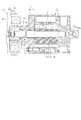
- FIG. 1 is a view showing a vane type compressor according to the present invention
- (a) is a side sectional view of the compressor.
- (b) is a cross-sectional view taken along the line AA in (a), and shows the rotor and vanes in phantom lines.
- FIG. 2A is a side sectional view showing a state in which a rotor is fixed to a drive shaft
- FIG. 2A is a diagram showing the entire configuration
- FIG. 2B is a view showing a movement restricting member (link-like member). It is an expanded sectional view showing the neighborhood.
- 3A and 3B are diagrams showing another example of the movement restricting member (link-like member), where FIG.
- FIG. 3A is a sectional view showing the vicinity of the movement restricting member (link-like member), and FIG. It is an expanded sectional view showing a member (link-like member).
- FIG. 4 is a side sectional view showing a conventional vane type compressor.
- FIG. 5 is a diagram for explaining a conventional configuration that regulates axial movement of the drive shaft and the rotor.
- FIG. 1 shows a vane compressor 1 suitable for a refrigeration cycle using a refrigerant as a working fluid.
- the vane compressor 1 includes a drive shaft 2, a rotor 3 that is fixed to the drive shaft 2 and rotates as the drive shaft 2 rotates, a vane 4 attached to the rotor 3, and the drive shaft 2.
- a housing 5 that supports the rotor 3 and the vanes 4 while supporting the rotor 3 and the vanes 4 is provided.
- the left side is the front side and the right side is the rear side.
- the housing 5 is configured by combining two members of a first housing member 10 and a second housing member 20.
- the first housing member 10 houses the rotor 3 and has a cam surface 11.
- the cylinder forming portion 12 is formed on the inner peripheral surface, and the first side block forming portion 13 is integrally formed so as to close one end side (rear side) of the cylinder forming portion 12 in the axial direction. ing.
- the inner peripheral surface (cam surface 11) of the cylinder forming portion 12 is formed in a perfect circle in cross section, and the axial length is substantially equal to the axial length of the rotor 3 described later.
- the second housing member 20 includes a second side block forming portion 21 that is in contact with an end face on the other end side (front side) in the axial direction of the cylinder forming portion 12 and closes the other end side.
- a shell forming portion formed integrally with the side block forming portion 21 and extending in the axial direction of the drive shaft 2 so as to surround the outer peripheral surfaces of the cylinder forming portion 12 and the first side block forming portion 13. 22.
- the first housing member 10 and the second housing member 20 are fastened in the axial direction via fastening bolts 9, and the first side block forming portion 13 of the first housing member 10 and the second housing member 10 are fastened.
- a seal member 7 such as an O-ring is interposed between the shell forming portion 22 of the housing member 20 and the housing member 20 is hermetically sealed.
- the second housing member 20 is integrally formed with a boss portion 23 extending from the second side block forming portion 21 to the front side.
- a pulley 31 (shown by an alternate long and short dash line) that transmits rotational power to the drive shaft 2 is rotatably mounted on the boss portion 23, and rotational power is transmitted from the pulley to the drive shaft 2 via an electromagnetic clutch 32. It has become.
- the drive shaft 2 is rotatably supported by the first side block forming portion 13 and the second side block forming portion 21 via bearings 14 and 24 (for example, plain bearings), and the front end portion is
- the second housing member 20 protrudes into the boss portion 23 and is hermetically sealed with the boss portion 23 by a seal member 25 provided between the boss portion 23 and the second boss portion 23. Therefore, the atmospheric pressure acts on the front end portion of the drive shaft 2 in a state of protruding to the outside of the housing 5.
- the drive shaft 2 has at least one portion having an outer diameter larger than the outer diameter of the portion where the rotor 3 is fixed, on the front side of the portion where the rotor 3 is fixed. In this example, the outer diameter of the portion where the rotor 3 is fixed is smaller than the outer diameter of the portion supported by the front bearing 24 where strength is required.
- the electromagnetic clutch 32 is connected to a front end protruding from the second housing member 20 (second side block forming portion 21) of the drive shaft 2 via a leaf spring 34 attached in the axial direction with a bolt 33.
- the clutch plate 35 is fixed so as to oppose the friction surface 31 a of the pulley 31, and the clutch plate 35 is attracted to the pulley 31 by energization of the excitation coil 36 included in the pulley 31. Is transmitted to the drive shaft 2 via the clutch plate 35 and the plate spring 34.
- the rear end portion of the drive shaft 2 is inserted into the bottomed support concave portion 15 formed in the first side block forming portion 13 while leaving a space 15a between the bottom portion and the drive shaft 2 after being inserted.
- the bearing 14 is provided around the end.
- the rotor 3 has a perfect circular cross section, and the drive shaft 2 is inserted through an insertion hole 3a provided at the center of the rotor 3 so that the shaft centers coincide with each other, and the rotor 3 is shrink-fitted or the like. It is fixed by. Further, the axial center O ′ of the inner peripheral surface (cam surface 11) of the cylinder forming portion 12 and the axial center O of the rotor 3 (drive shaft 2) are the outer peripheral surface of the rotor 3 and the inner peripheral surface of the cylinder forming portion 12 ( The cam surface 11) is shifted so as to come into contact with one place in the circumferential direction (offset by a half of the difference between the inner diameter of the cylinder forming portion 12 and the outer diameter of the rotor 3).
- a compression space 40 is defined between the outer peripheral surface and the outer peripheral surface.
- the second housing member 20 is formed with a suction port for sucking working fluid (refrigerant gas) from the outside and a discharge port for discharging the working fluid (refrigerant gas) to the outside (not shown), and a cylinder forming portion of the first housing member 10 12, a suction port is provided near the front side in the rotational direction of the rotor 3 with respect to a portion (radial seal portion 45) in which the outer peripheral surface of the rotor 3 is in sliding contact with the inner peripheral surface (cam surface 11) of the cylinder forming portion 12.
- a suction port 16 that communicates is formed, and a discharge port 17 that communicates with the discharge port is formed in the vicinity of the rear side in the rotational direction of the rotor 3.
- reference numeral 18 denotes a screw hole for screwing the connector.
- the discharge port 17 has a counterbore 17a that is recessed in a curved shape along the circumferential direction at the opening end with the inner peripheral surface (cam surface 11) of the cylinder forming portion 12, and the compressed gas is stored in this seat. It is discharged through the bore 17a.
- a discharge chamber 37 is formed over a predetermined range in the circumferential direction between the cylinder forming portion 12 of the first housing member 10 and the shell forming portion 22 of the second housing member 20.
- the discharge chamber 37 is opened and closed by a discharge valve 38 provided in the discharge chamber 37 so as to be opened and closed.
- a discharge space 39 to which a discharge port is connected is formed between the first side block forming portion 13 of the first housing member 10 and the shell forming portion 22 of the second housing member 20, and the discharge chamber 37. Communicates with the discharge space 39 via an oil separator 28.
- the discharge chamber 37 and the discharge space 39 constitute a high-pressure space that accommodates the fluid discharged from the discharge port 17.
- the oil separated from the working fluid by the oil separator is provided between the lower portion of the first side block forming portion 13 of the first housing member 10 and the lower portion of the shell forming portion 22 of the second housing member 20.
- An oil reservoir chamber 18 for storing (having a pressure corresponding to the pressure of the discharge gas) is provided.
- a plurality of vane grooves 6 are formed on the outer peripheral surface of the rotor 3, and the vanes 4 are slidably inserted into the respective vane grooves 6.
- the vane groove 6 is opened not only on the outer peripheral surface of the rotor 3 but also on the end surface facing the first side block forming portion 13 and the second side block forming portion 21, and a back pressure chamber 6 a is formed at the bottom portion. Has been.
- a plurality of the vane grooves 6 are formed at equal intervals in the circumferential direction, and in this example, the vane grooves 6 are formed so as to be parallel to each other at two positions different in phase by 180 degrees, and a plane including the vane 4; A plane parallel to the vane 4 and including the axis O of the drive shaft 2 is formed (offset) by a predetermined distance.
- the vane 4 is formed such that the width along the axial direction of the drive shaft 2 is equal to the axial length of the rotor 3, and the length in the insertion direction (sliding direction) into the vane groove 6 is the length of the vane groove 6. It is formed approximately equal to the length in the same direction.
- the vane 4 protrudes from the vane groove 6 due to the back pressure supplied to the back pressure chamber 6 a of the vane groove 6, and the tip part can come into contact with the inner peripheral surface (cam surface 11) of the cylinder forming part 12. ing.
- the compression space 40 is partitioned into a plurality of compression chambers 41 by the vanes 4 slidably inserted into the vane grooves 6, and the volume of each compression chamber 41 changes as the rotor 3 rotates. ing.
- the first side block forming portion 13 has an end surface facing the end surface in the axial direction of the rotor 3, and a first recess 42 and a second recess that can communicate with the back pressure chamber 6 a provided at the bottom of the vane groove 6.
- a recess 43 is formed.
- the first recess 42 communicates with the oil reservoir chamber 18, and extends from the position of the radial seal portion 40 to a position just before the discharge port 17 (before the counterbore 17 a).
- the tip of the vane 4 is communicated with the bottom of the vane groove 6 (the back pressure chamber 6a) in a stroke in front of the discharge port 17 from the radial seal portion 40.
- the second recess 43 communicates with the discharge space 39, and the position where the tip end portion of the vane 4 is located at the discharge port 17, in this example, the position approaching the discharge port 17 (the counterbore 17a). From the start end of the vane 4 to the radial seal portion 40, and communicates with the bottom portion of the vane groove 6 (back pressure chamber 6a) in a stroke in which the tip end portion of the vane 4 is in the range from the discharge port 17 to the radial seal portion 40. It is supposed to be.
- a movement restricting member for restricting the movement of the drive shaft 2 relative to the rotor 3 in the axial direction is provided on the outer peripheral surface that does not interfere with the bearing 14 on the rear end side of the drive shaft 2.
- the movement restricting member is constituted by a ring-shaped member 50 fixed to the outer peripheral surface of the drive shaft 2 by press-fitting.
- the outer diameter of the drive shaft where the ring-shaped member 50 is press-fitted may be formed to be the same as or slightly smaller than the outer diameter of the part where the rotor is press-fitted.
- the outer diameter of the drive shaft on the insertion start end side where the ring-shaped member 50 is press-fitted is slightly reduced, so that the ring-shaped member 50 You may make it function as a guide at the time of press fit.
- the ring-shaped member 50 is disposed inside the rotor. Specifically, as shown in FIG. 2, among the inner peripheral wall of the insertion hole 3 a through which the drive shaft 2 of the rotor 3 is inserted, there is a gap between the opening peripheral edge on the rear end side and the outer peripheral surface of the drive shaft 2. An annular recess 3b is formed, and the ring-shaped member 50 is accommodated in the annular recess 3b so that the insertion end thereof faces the rotor.
- the outer diameter of the ring-shaped member 50 is larger than the inner diameter of the rotor 3, so that the ring-shaped member 50 can come into contact with the rotor when the drive shaft to which the ring-shaped member 50 is press-fitted and moved moves in the axial direction.
- the axial length of the ring-shaped member 50 is set to be shorter than the axial length of the annular recess 3b, and is fixed so as not to contact the first side block forming portion 13.
- the ring-shaped member 50 may be fixed in a state of being in contact with the rotor 3 in the axial direction, but the drive shaft 2 is displaced in the axial direction with respect to the rotor 3 and is in contact with the end surface of the rotor 3.
- the outer peripheral surface of the ring-shaped member 50 is set so that a predetermined clearance is formed with respect to the inner peripheral surface of the annular recess 3b of the rotor 3 (so as not to contact the rotor in the radial direction). It is fixed to the outer peripheral surface of the drive shaft 2).
- the ring-shaped member 50 is tapered at both ends in the axial direction of the inner peripheral surface so that it can be smoothly pressed into the outer peripheral surface of the drive shaft.
- the friction force between the drive shaft 2 and the rotor 3 becomes a dynamic friction force smaller than the maximum static friction force. That is, when the rotor 3 and the drive shaft 2 slip relative to each other in the circumferential direction, the frictional force between the rotor 3 and the drive shaft 2 is reduced.
- the outer diameter of the portion of the drive shaft 2 where the rotor 3 is fixed is formed smaller than the outer diameter of the portion supported by the front bearing 24.
- the outer diameter can be reduced, and the axial slip of the drive shaft can be suppressed while meeting the demand for a smaller diameter compressor.
- the ring-shaped member 50 is accommodated in the annular recess 3b formed on the inner peripheral wall of the rotor 3, the position of the bearing 14 is reduced by providing the ring-shaped member 50 without interfering with the bearing 14. The inconvenience of having to change the diameter of the bearing 14 is also eliminated.
- the example in which the annular recess 3b is provided in the inner peripheral wall of the rotor 3 and the ring-shaped member 50 is accommodated therein is shown.
- the rotor The ring-shaped member 50 may be press-fitted and fixed to the outer peripheral surface between the rotor 3 and the bearing 14 without providing the annular recess 3b in FIG.
- FIG. 3 shows another configuration example of the ring-shaped member 50.
- the ring-shaped member 50 shown here is provided with a taper 50 a for smoothly press-fitting the ring-shaped member 50 into the outer peripheral surface of the drive shaft 2 at both axial ends of the inner peripheral surface of the ring-shaped member 50. This is the same as the above configuration example.
- retreat portions 50b are further formed at both ends in the axial direction.
- the retracting portion 50b may be formed in any way as long as the outer peripheral side of the ring-shaped member 50 is not in contact with the rotor 3, but in this example is formed in a tapered shape.
- Tapered retracting portions 50b formed at both axial end portions of the outer peripheral surface of the ring-shaped member 50 are formed larger than the taper 50a at both axial end portions of the inner peripheral surface, and the rotor 3 and the ring-shaped member 50 are formed.
- the position in the radial direction of the abutting portion is brought closer to the inside (the abutting against the rotor 3 at a portion closer to the drive shaft 2 than the center (center line ⁇ ) of the radial thickness of the ring-shaped member 50) Possible).
- a retracting portion 50 b that avoids contact with the rotor 3 is provided at the axial end of the outer peripheral surface of the ring-shaped member 50 without reducing the thickness of the ring-shaped member 50. Therefore, while maintaining the rigidity of the ring-shaped member 50 and securing the strong binding force between the ring-shaped member 50 and the drive shaft 2, the radial position of the contact portion between the ring-shaped member 50 and the rotor 3 is set to the inner side. Can be sent to. For this reason, even when the ring-shaped member 50 comes into contact with the rotor 3 slipping in the circumferential direction, the torque received by the ring-shaped member 50 from the rotor 3 can be reduced, and the ring-shaped member 50 can rotate together. It becomes possible to prevent.
- the compressor having two vanes 4 has been described.
- the same configuration can be adopted in three or more vane-type compressors. Shows an example in which the housing 5 is configured by combining the first housing member 10 and the second housing member 20, but the side block forming portion (the first side block forming portion 13, the second side block forming) is shown.
- a similar configuration may also be adopted in a compressor in which the part 21) is formed as a separate member and assembled.
- a key is press-fitted into another structure provided on the outer peripheral surface of the drive shaft 2, for example, a key groove formed on the outer peripheral surface of the drive shaft. You may make it comprise.
Landscapes
- Engineering & Computer Science (AREA)
- Mechanical Engineering (AREA)
- General Engineering & Computer Science (AREA)
- Applications Or Details Of Rotary Compressors (AREA)
- Rotary Pumps (AREA)
Abstract
【課題】液圧縮により、駆動軸とこれに装着されたロータとが相対的に周方向にスリップした場合でも、簡易な構成で駆動軸のロータに対する軸方向の移動を規制する。 【解決手段】駆動軸2のハウジング外に突出する側とは反対側の外周面に、駆動軸2のロータ3に対する軸方向の移動を規制する移動規制部材が設けられる。この移動規制部材は、リング状部材50で構成され、駆動軸2の外周面に圧入により固定されるとともに、ロータ3の駆動軸2を挿通させる挿通孔3aの開口端周縁に設けられた環状凹部3bに収容するとよい。
Description
本発明は、ベーン型圧縮機に関し、特に起動時の液圧縮により駆動軸がロータに対して軸方向にずれることを防止する機構を備えたベーン型圧縮機に関する。
一般的に、ベーン型圧縮機は、図4に示されるように、低圧空間及び高圧空間を形成するハウジング5と、カム面11が形成され、ハウジング5の一部を構成するシリンダ形成部12と、シリンダ形成部12の軸方向の両端を閉塞し、ハウジング5の一部を構成する一対のサイドブロック形成部13,21と、一対のサイドブロック形成部13,21に軸受14,24を介して回転自在に支持された駆動軸2と、駆動軸2に固装されてシリンダ形成部12内に回転可能に収容されたロータ3と、ロータ3に形成された複数のベーン溝6と、ベーン溝6に摺動自在に挿入され、先端がベーン溝6から出没してカム面11を摺動する複数のベーン4とを備え、シリンダ形成部12と一対のサイドブロック形成部13,21とにより閉塞された空間に、ロータ3及びベーン4によって圧縮室41が画成され、低圧空間から圧縮室41に作動流体を吸入し、圧縮した後に高圧空間へ吐出するようにしている。
駆動軸2は、回転動力を外部から伝達するために前端部がハウジング5(第2のサイドブロック形成部21)から外部に突出し、クラッチ式の圧縮機においては、駆動軸2のハウジング5から突出したフロント側の端部に、ハウジング5のボス部23に回転可能に設けられたプーリ31と所定の間隔を開けて対峙する電磁クラッチ32のクラッチ板35が固定されている。また、ロータ3は、駆動軸2の外周面に焼き嵌め等により強固に固定されている。
このようなベーン型圧縮機においては、シリンダ形成部12内に液冷媒やオイルが存在している状態で起動すると、液体を圧縮することになり、圧縮室41の圧力が著しく高圧となって、ベーン4やこれを支持するロータ3に過剰な力が作用する。
ロータ3と駆動軸2とは、上述したように焼嵌め等により強固に固定されているが、ロータ3やベーン4に液圧縮による過剰な圧力が作用すると、ロータ3と駆動軸2との間の最大静止摩擦力を超えてしまい、ロータ3と駆動軸2とが相対的に周方向にスリップする現象が生じる。このようなスリップが一旦生じると、ロータ3と駆動軸2との間の摩擦力は、最大静止摩擦力よりも小さい動摩擦力となる。即ち、ロータ3と駆動軸2とが相対的に周方向にスリップしているときは、ロータ3と駆動軸2との間の摩擦力が低下することとなる。
ロータ3と駆動軸2とは、上述したように焼嵌め等により強固に固定されているが、ロータ3やベーン4に液圧縮による過剰な圧力が作用すると、ロータ3と駆動軸2との間の最大静止摩擦力を超えてしまい、ロータ3と駆動軸2とが相対的に周方向にスリップする現象が生じる。このようなスリップが一旦生じると、ロータ3と駆動軸2との間の摩擦力は、最大静止摩擦力よりも小さい動摩擦力となる。即ち、ロータ3と駆動軸2とが相対的に周方向にスリップしているときは、ロータ3と駆動軸2との間の摩擦力が低下することとなる。
一方、液圧縮時の圧縮室41内の高圧圧力は、ロータ3とサイドブロック形成部13との間のクリアランスや軸受14と駆動軸2又はサイドブロック形成部13との間のクリアランスを介して駆動軸2の背後に回り込み、この回り込んだ圧力が駆動軸2の後端に作用する。前述の通り、ロータ3と駆動軸2とが相対的に周方向にスリップしているときは、ロータ3と駆動軸2との間の摩擦力が低下しているため、液圧縮時には、ロータ3と駆動軸2とが周方向にスリップするだけでなく、駆動軸2の後端に作用する高圧圧力により、駆動軸2が前端側に向かって付勢され、ロータ3に対して軸方向に移動する現象が生じる。
このような駆動軸2の軸方向に対する移動が生じると、駆動軸2の前端部に設けられた電磁クラッチ32のクラッチ板35とプーリ31との間隔(クラッチギャップα)が拡大し、クラッチ作動時において、クラッチ板35の確実な吸着が困難となり、回転動力を確実に伝達できなくなる不都合が生じる。
そこで、このような不都合に対処するために、例えば、図5に示されるように、ロータ3の挿通孔3aに駆動軸2を挿入した上でロータ3の端面をダイス100で加圧し、これによりロータ3の一部を駆動軸2の外周溝部101に塑性流動させて、ロータ3と駆動軸2とを一体化する構成も有用である(特許文献1参照)。
このような構成によれば、液圧縮により、駆動軸2とロータ3とが相対的に周方向にスリップした場合でも、駆動軸2のロータ3に対する軸方向の移動が規制されているので、プーリ31とこれに対峙する電磁クラッチ32のクラッチ板35との間隔(クラッチギャップα)が増大することはなくなり、クラッチ作動時において、クラッチ板35の確実な吸着が可能となる。
しかしながら、特許文献1で示される構成においては、駆動軸のロータに対する軸方向の移動を規制するために、ロータの端面をダイスで加圧してロータの一部を駆動軸に形成された外周溝部に塑性流動させて駆動軸とロータとを一体化させているので、駆動軸のロータに対する軸方向の移動を規制する構造の形成が大掛かりとなり、また、ロータの一部を塑性流動させるので、ロータの寸法精度に少なからず影響が出てくることになり、厳格な寸法管理が必要となるものであった。
本発明は、係る事情に鑑みてなされたものであり、液圧縮により、万が一、ロータと駆動軸とが相対的に周方向にスリップした場合でも、簡易な構成で駆動軸のロータに対する軸方向の移動を規制することが可能なベーン型圧縮機を提供することを主たる課題としている。
上記課題を達成するために、本発明に係るベーン型圧縮機は、ハウジングと、カム面が形成され、前記ハウジングの一部を構成するシリンダ形成部と、前記シリンダ形成部の軸方向の両端を閉塞し、前記ハウジングの一部を構成する一対のサイドブロック形成部と、前記一対のサイドブロック形成部に軸受を介して回転自在に支持され、一端が一方のサイドブロック形成部から前記ハウジング外へ突出する駆動軸と、前記駆動軸に固装されて前記シリンダ形成部内に回転可能に収容されるロータと、前記ロータに形成された複数のベーン溝と、前記ベーン溝に摺動自在に挿入され、先端部が前記ベーン溝から出没して前記カム面を摺動する複数のベーンと、前記シリンダ形成部と前記一対のサイドブロック形成部とにより閉塞された空間に、前記ロータと前記ベーンとによって画成される圧縮室と、を備えたベーン型圧縮機において、前記駆動軸の他端側の外周面に、該駆動軸の前記ロータに対する軸方向の移動を規制する移動規制部材が設けられていることを特徴としている。
したがって、駆動軸のハウジング外に突出する側とは反対側の外周面に駆動軸のロータに対する軸方向の移動を規制する移動規制部材が設けられているので、仮にロータと駆動軸とが相対的に周方向にスリップして、ロータと駆動軸との間の摩擦力が低下しても、駆動軸の両端の圧力差に起因する駆動軸のロータに対する軸方向の移動をこの移動規制部材によって規制することが可能となる。
このため、電磁クラッチを備えた圧縮機においては、プーリとこれに対峙するクラッチ板との間隔が広がる不都合はなくなり、安定した吸着力を維持することが可能となる。
このため、電磁クラッチを備えた圧縮機においては、プーリとこれに対峙するクラッチ板との間隔が広がる不都合はなくなり、安定した吸着力を維持することが可能となる。
ここで、前記駆動軸は、前記ロータが固装されている部位の外径が、前記一端側において、前記軸受によって支持される部位の外径よりも小さくすることが好ましい。
このような構成によれば、ロータの外径を小さくすることができるので、圧縮機の小型化の要請に応えつつ、駆動軸の軸方向の移動を抑えることが可能となる。
このような構成によれば、ロータの外径を小さくすることができるので、圧縮機の小型化の要請に応えつつ、駆動軸の軸方向の移動を抑えることが可能となる。
また、前記移動規制部材は、リング状部材で構成され、前記駆動軸の外周面に圧入により固定されるとともに、前記ロータの前記駆動軸を挿通させる挿通孔の内周壁に設けられた環状凹部に収容されることが好ましい。
移動規制部材をリング状部材とすることで、圧入代の管理が容易となり、また、移動規制部材を、ロータの駆動軸を挿通させる挿通孔の内周壁に設けられた環状凹部に収容する構成とすることで、駆動軸の外周面に固定する移動規制部材と駆動軸を支持する軸受とが干渉する不都合がなくなり、また、干渉を避けるために軸受の位置をロータから大きく離して設けたり、軸受の径を大きくして移動規制部材の外側に設けたりする不都合がなくなる。
また、リング状部材は、駆動軸への圧入のし易さを考慮して、その内周面の少なくとも前記ロータと対峙する側の軸方向端部にテーパを施すようにするとよい。
さらに、好ましくは、リング状部材の外周面の少なくとも前記ロータと対峙する側の軸方向端部にロータとの接触を回避する退避部を形成し、これにより、リング状部材の径方向の厚みの中央よりも前記駆動軸に寄った部位が前記ロータと当接するようにするとよい。
リング状部材とロータとの接触部位が、径方向の厚みの中央よりも外側(駆動軸から遠ざかった部位)の部位である場合には、ロータの軸方向端面とリング状部材とが当接する部位も駆動軸から遠ざかるので、ロータとリング状部材とが当接した際にロータの周方向のスリップによって生じるトルクが大きくなり、リング状部材がロータと共回りする可能性が大きくなるが、上述のような構成とすれば、ロータとリング状部材との当接箇所の径方向の位置を内側に寄せることが可能となるので、周方向にスリップするロータにリング状部材が当接した場合でもリング状部材が受けるトルクを小さくすることが可能となり、リング状部材の共回りの恐れを抑えることが可能となる。
リング状部材とロータとの接触部位が、径方向の厚みの中央よりも外側(駆動軸から遠ざかった部位)の部位である場合には、ロータの軸方向端面とリング状部材とが当接する部位も駆動軸から遠ざかるので、ロータとリング状部材とが当接した際にロータの周方向のスリップによって生じるトルクが大きくなり、リング状部材がロータと共回りする可能性が大きくなるが、上述のような構成とすれば、ロータとリング状部材との当接箇所の径方向の位置を内側に寄せることが可能となるので、周方向にスリップするロータにリング状部材が当接した場合でもリング状部材が受けるトルクを小さくすることが可能となり、リング状部材の共回りの恐れを抑えることが可能となる。
なお、ベーン型圧縮機のハウジングは特に限定されるものではないが、ハウジングは、内周面にカム面が形成されたシリンダ形成部と、前記シリンダ形成部の軸方向の一端側を閉塞する第1のサイドブロック形成部とが一体に形成された第1のハウジング部材と、前記シリンダ形成部の軸方向の他端側を閉塞する第2のサイドブロック形成部と、前記第1のハウジング部材の外周面を覆うシェル形成部とが一体に形成された第2のハウジング部材とを組み合わせて構成されるようにしてもよい。
以上述べたように、本発明によれば、駆動軸のハウジング外に突出する側とは反対側の外周面に、該駆動軸のロータに対する軸方向の移動を規制する移動規制部材が設けられているので、ロータと駆動軸との間の摩擦力が動摩擦力となっても、駆動軸のロータに対する軸方向の移動は、駆動軸に圧入された移動規制部材によって規制することが可能となる。
したがって、電磁クラッチを備えた圧縮機においては、プーリとこれに対峙するクラッチ板との間隔が広がる不都合がなくなり、安定した吸着力を維持することが可能となる。
したがって、電磁クラッチを備えた圧縮機においては、プーリとこれに対峙するクラッチ板との間隔が広がる不都合がなくなり、安定した吸着力を維持することが可能となる。
特に、移動規制部材を、リング状部材で構成し、駆動軸の外周面に圧入により固定すると共に、ロータの駆動軸を挿通させる挿通孔の内周壁に設けられた環状凹部に収容することで、移動規制部材の圧入代の管理が容易となり、また、移動規制部材が軸受と干渉する不都合がなくなる。このため、移動規制部材と軸受との干渉を避けるために、軸受の位置をロータから大きく離して設けたり、軸受の径を大きくして移動規制部材の外側に設けたりする不都合がなくなり、圧縮機の小型化を図ることが可能となる。
以下、本発明に係るベーン型圧縮機について図面を参照しながら説明する。
図1において、冷媒を作動流体とする冷凍サイクルに適したベーン型圧縮機1が示されている。このベーン型圧縮機1は、駆動軸2と、駆動軸2に固定されて当該駆動軸2の回動に伴い回転するロータ3と、このロータ3に取り付けられるベーン4と、駆動軸2を回転自在に支持すると共にロータ3及びベーン4を収容するハウジング5とを有して構成されている。なお、図1において、左側をフロント側、右側をリア側とする。
ハウジング5は、第1のハウジング部材10と第2のハウジング部材20との2つの部材を組み合わせて構成されているもので、第1のハウジング部材10は、ロータ3を収納すると共にカム面11が内周面に形成されたシリンダ形成部12と、このシリンダ形成部12の軸方向の一端側(リア側)を閉塞するように一体に形成された第1のサイドブロック形成部13とから構成されている。シリンダ形成部12の内周面(カム面11)は、断面が真円に形成され、軸方向の長さが後述するロータ3の軸方向の長さにほぼ等しく形成されている。
第2のハウジング部材20は、シリンダ形成部12の軸方向の他端側(フロント側)の端面に当接してこの他端側を閉塞する第2のサイドブロック形成部21と、この第2のサイドブロック形成部21に一体に形成されて駆動軸2の軸方向に延設され、前記シリンダ形成部12及び第1のサイドブロック形成部13の外周面を包囲するように形成されたシェル形成部22とを有して構成されている。
そして、これら第1のハウジング部材10と第2のハウジング部材20とは、締結ボルト9を介して軸方向に締結され、第1のハウジング部材10の第1のサイドブロック形成部13と第2のハウジング部材20のシェル形成部22との間は、Oリング等のシール部材7が介在されて気密よくシールされている。
また、第2のハウジング部材20には、第2のサイドブロック形成部21からフロント側に延設されたボス部23が一体に形成されている。このボス部23には、駆動軸2に回転動力を伝えるプーリ31(一点鎖線で示す)が回転自在に外装され、このプーリから電磁クラッチ32を介して回転動力が駆動軸2に伝達されるようになっている。
駆動軸2は、第1のサイドブロック形成部13と第2のサイドブロック形成部21とに軸受14,24(例えば、プレーンベアリング)を介して回転自在に支持されているもので、前端部は第2のハウジング部材20のボス部23内に突出し、ボス部23との間に設けられたシール部材25によって該ボス部23との間が気密よくシールされている。したがって、駆動軸2の前端部は、ハウジング5の外部に突出した状態で大気圧が作用するようになっている。
また、駆動軸2は、ロータ3が固装されている部位よりもフロント側において、ロータ3が固装されている部位の外径よりも大きい外径の部位を少なくとも1箇所有している。この例では、ロータ3が固装されている部位の外径が、強度が要請されるフロント側の軸受24によって支持される部位の外径よりも小さくなっている。
また、駆動軸2は、ロータ3が固装されている部位よりもフロント側において、ロータ3が固装されている部位の外径よりも大きい外径の部位を少なくとも1箇所有している。この例では、ロータ3が固装されている部位の外径が、強度が要請されるフロント側の軸受24によって支持される部位の外径よりも小さくなっている。
なお、前記電磁クラッチ32は、駆動軸2の第2のハウジング部材20(第2のサイドブロック形成部21)から突出した前端部に、軸方向にボルト33にて取り付けられた板バネ34を介してクラッチ板35をプーリ31の摩擦面31aと対峙して固定し、プーリ31に内包された励磁コイル36への通電によりクラッチ板35をプーリ31に吸着させ、このプーリ31に与えられる走行用エンジンからの回転動力をクラッチ板35及び板バネ34を介して駆動軸2に伝達するようになっている。
これに対して、駆動軸2の後端部は、第1のサイドブロック形成部13に形成された有底の支持凹部15に底部との間に空間15aを残しつつ挿入され、挿入された後端部の周囲に前記軸受14が設けられている。
前記ロータ3は、断面が真円状に形成され、その軸中心に設けられた挿通孔3aに前記駆動軸2が挿通され、互いの軸中心を一致させた状態で駆動軸2に焼嵌め等により固定されている。また、シリンダ形成部12の内周面(カム面11)の軸中心O’とロータ3(駆動軸2)の軸中心Oとは、ロータ3の外周面とシリンダ形成部12の内周面(カム面11)とが周方向の一箇所で当接するようにずらして設けられている(シリンダ形成部12の内径とロータ3の外径との差の1/2だけずらして設けられている)。そして、シリンダ形成部12と第1のサイドブロック形成部13及び第2のサイドブロック形成部21とにより閉塞された空間には、シリンダ形成部12の内周面(カム面11)とロータ3の外周面との間に圧縮空間40が画成されている。
また、第2のハウジング部材20には、作動流体(冷媒ガス)を外部から吸入する吸入口および外部へ吐出する吐出口が形成され(図示せず)、第1のハウジング部材10のシリンダ形成部12には、ロータ3の外周面がシリンダ形成部12の内周面(カム面11)と摺接する部位(ラジアルシール部45)に対して、ロータ3の回転方向の前方側近傍に吸入口と連通する吸入ポート16が形成され、また、ロータ3の回転方向の後方側直近に吐出口と連通する吐出ポート17が形成されている。なお、図1(b)において、18は、連結具を螺合するねじ穴である。
吐出ポート17は、シリンダ形成部12の内周面(カム面11)との開口端に周方向に沿って湾曲状に凹ませた座ぐり(カウンターボア)17aを有し、圧縮ガスはこの座ぐり17aを介して吐出される。第1のハウジング部材10のシリンダ形成部12と第2のハウジング部材20のシェル形成部22との間には、周方向の所定範囲に亘って吐出室37が形成され、前記吐出ポート17はこの吐出室37に開口し、吐出室37に設けられた吐出弁38により開閉可能に閉塞されている。
また、第1のハウジング部材10の第1のサイドブロック形成部13と第2のハウジング部材20のシェル形成部22との間は、吐出口が接続する吐出空間39が形成され、前記吐出室37は、オイル分離器28を介してこの吐出空間39に連通している。
これら吐出室37および吐出空間39により、吐出ポート17から吐出した流体を収容する高圧空間が構成されている。さらに、第1のハウジング部材10の第1のサイドブロック形成部13の下部と第2のハウジング部材20のシェル形成部22の下部との間には、オイル分離器によって作動流体から分離されたオイル(吐出ガスの圧力に相当する圧力を有する)を溜めるオイル溜まり室18が設けられている。
これら吐出室37および吐出空間39により、吐出ポート17から吐出した流体を収容する高圧空間が構成されている。さらに、第1のハウジング部材10の第1のサイドブロック形成部13の下部と第2のハウジング部材20のシェル形成部22の下部との間には、オイル分離器によって作動流体から分離されたオイル(吐出ガスの圧力に相当する圧力を有する)を溜めるオイル溜まり室18が設けられている。
前記ロータ3の外周面には、複数のベーン溝6が形成され、それぞれのベーン溝6には、ベーン4が摺動自在に挿入されている。ベーン溝6は、ロータ3の外周面のみならず第1のサイドブロック形成部13及び第2のサイドブロック形成部21と対峙する端面にも開口されており、底部には背圧室6aが形成されている。このベーン溝6は、周方向に等間隔に複数形成されているもので、この例では、180度位相が異なる2箇所に互いに平行となるように形成されており、ベーン4を含む平面と、ベーン4と平行をなし駆動軸2の軸心Oを含む平面とが所定の距離だけ離れた状態(オフセットした状態)で形成されている。
ベーン4は、駆動軸2の軸方向に沿った幅が前記ロータ3の軸方向の長さに等しく形成され、ベーン溝6への挿入方向(摺動方向)の長さは、ベーン溝6の同方向の長さに略等しく形成されている。このベーン4は、ベーン溝6の背圧室6aに供給される背圧により、ベーン溝6から突出されて先端部がシリンダ形成部12の内周面(カム面11)に当接可能となっている。
したがって、前記圧縮空間40は、ベーン溝6に摺動自在に挿入されたベーン4によって複数の圧縮室41に仕切られ、それぞれの圧縮室41の容積は、ロータ3の回転によって変化するようになっている。
なお、第1のサイドブロック形成部13のロータ3の軸方向端面と対峙する端面には、ベーン溝6の底部に設けられた背圧室6aと連通可能な第1の凹部42と第2の凹部43が形成されている。
第1の凹部42は、前記オイル溜まり室18と連通しているもので、ベーン4の先端部がラジアルシール部40の位置から吐出ポート17に差し掛かる手前(座ぐり17aより手前)の範囲にかけて形成され、ベーン4の先端部がラジアルシール部40から吐出ポート17の手前にある行程においてベーン溝6の底部(背圧室6a)と連通するようになっている。
これに対して、第2の凹部43は、前記吐出空間39と連通するもので、ベーン4の先端部が吐出ポート17にある位置、この例では、吐出ポート17に差し掛かる位置(座ぐり17aの始端に差し掛かる位置)からラジアルシール部40にかけて形成され、ベーン4の先端部が吐出ポート17からラジアルシール部40までの範囲にある行程においてベーン溝6の底部(背圧室6a)と連通するようになっている。
したがって、ベーン溝6の底部(背圧室6a)が第1の凹部42に連通すると、オイル溜まり室18から供給された吐出圧力に相当する圧力を有するオイルが背圧室6aに送り込まれ、ベーン溝6の底部(背圧室6a)が第2の凹部42に連通すると、吐出空間39から供給された吐出ガスが背圧室6aに直接送り込まれる。
そして、この例では、駆動軸2の後端側の軸受14と干渉しない外周面に、該駆動軸2のロータ3に対する軸方向の移動を規制する移動規制部材が設けられている。この移動規制部材は、この例では、駆動軸2の外周面に圧入により固定されたリング状部材50によって構成されている。
このリング状部材50が圧入されている部位の駆動軸の外径は、ロータが圧入されている部位の外径と同じか、僅かに小さくなるように形成するとよい。また、リング状部材50の駆動軸への取り付けを容易にするために、リング状部材50が圧入される箇所の挿入始端側の駆動軸の外径を僅かに小さくして、リング状部材50の圧入時のガイドとして機能させるようにしてもよい。
このリング状部材50が圧入されている部位の駆動軸の外径は、ロータが圧入されている部位の外径と同じか、僅かに小さくなるように形成するとよい。また、リング状部材50の駆動軸への取り付けを容易にするために、リング状部材50が圧入される箇所の挿入始端側の駆動軸の外径を僅かに小さくして、リング状部材50の圧入時のガイドとして機能させるようにしてもよい。
また、リング状部材50は、ロータの内側に配置されている。具体的には、図2にも示されるように、ロータ3の駆動軸2を挿通させる挿通孔3aの内周壁のうち、後端側の開口周縁に駆動軸2の外周面との間に間隙を形成する環状凹部3bを形成し、この環状凹部3bにリング状部材50をその挿入端がロータに近接して対峙するように収容している。
ここで、リング状部材50の外径は、ロータ3の内径よりも大きくなっており、リング状部材50が圧入固定された駆動軸が軸方向に動いたときにロータに当接出来るようになっている。
また、リング状部材50の軸方向の長さは、環状凹部3bの軸方向の長さよりも短く設定され、第1のサイドブロック形成部13と当接しないように固定されている。このリング状部材50は、ロータ3に対して軸方向で当接させた状態で固定してもいいが、駆動軸2がロータ3に対して軸方向にずれてロータ3の端面に当接した場合でもプーリ31と電磁クラッチ32のクラッチ板35との間隔(クラッチギャップα)が許容範囲を超えることがない程度に僅かなクリアランスを開けておくことが好ましい。
さらに、リング状部材50の外周面は、ロータ3の環状凹部3bの内周面に対して所定のクリアランスが形成されるように設定されている(ロータに対して径方向で当接しないように駆動軸2の外周面に固定されている)。
また、リング状部材50の軸方向の長さは、環状凹部3bの軸方向の長さよりも短く設定され、第1のサイドブロック形成部13と当接しないように固定されている。このリング状部材50は、ロータ3に対して軸方向で当接させた状態で固定してもいいが、駆動軸2がロータ3に対して軸方向にずれてロータ3の端面に当接した場合でもプーリ31と電磁クラッチ32のクラッチ板35との間隔(クラッチギャップα)が許容範囲を超えることがない程度に僅かなクリアランスを開けておくことが好ましい。
さらに、リング状部材50の外周面は、ロータ3の環状凹部3bの内周面に対して所定のクリアランスが形成されるように設定されている(ロータに対して径方向で当接しないように駆動軸2の外周面に固定されている)。
また、この例では、リング状部材50は、駆動軸の外周面に対してスムーズに圧入することができるように、内周面の軸方向の両端部にテーパ50aが施されている。
以上の構成において、シリンダ形成部12内に液冷媒やオイルが存在している状態で圧縮機が起動すると、液体を圧縮することになる。すると、圧縮室41の圧力が著しく高圧となり、ベーン4やこれを支持するロータ3に過剰な力が作用し、この力がロータ3と駆動軸2との間の最大静止摩擦力を超えると、ロータ3が駆動軸2の周方向にスリップし始める。
また、圧縮室41の圧力が著しく高圧になると、ロータ3と第1のサイドブロック形成部13との間のクリアランスや軸受14と駆動軸2又は第1のサイドブロック形成部13との間のクリアランスを介して駆動軸2の背後の空間15aの圧力が高められ、駆動軸2の両端に作用する圧力に大きな差が生じる。
駆動軸2とロータ3との周方向のスリップが一旦生じると、駆動軸2とロータ3との間の摩擦力は、最大静止摩擦力よりも小さい動摩擦力となる。即ち、ロータ3と駆動軸2とが相対的に周方向にスリップしているときは、ロータ3と駆動軸2との間の摩擦力が低下している。このため、駆動軸2の両端に作用する圧力の差により、駆動軸2がロータ3に対して相対的に軸方向(先端方向)に移動したとしても、駆動軸2の外周面には、ロータ3の内径より大きい外径を有するリング状部材50が圧入されて固定されているので、リング状部材50がロータ3に対して軸方向で当接した時点で駆動軸2のロータ3に対する軸方向の移動は阻止されることになる。
よって、プーリ31と対峙する電磁クラッチ32のクラッチ板35とプーリ31との間隔(クラッチギャップα)が拡大する不都合がなくなり、クラッチ作動時において、クラッチ板35の確実な吸着が確保され、クラッチ板35がプーリ31に対してスリップして回転動力を伝達できなくなる不都合がなくなる。
また、上述の構成においては、駆動軸2のロータ3が固装されている部位の外径が、フロント側の軸受24によって支持される部位の外径よりも小さく形成されているので、ロータの外径を小さくすることができ、圧縮機の小径化の要請に応えながら駆動軸の軸方向スリップを抑えることが可能となる。
さらに、リング状部材50は、ロータ3の内周壁に形成された環状凹部3bに収容されているので、軸受14と干渉することもなく、リング状部材50を設けたことで軸受14の位置や軸受14の径を変更しなければならない不都合もなくなる。
尚、上述の構成においては、ロータ3の内周壁に環状凹部3bを設けてそこにリング状部材50を収容する例を示したが、軸受14との干渉を避けることができるのであれば、ロータ3に環状凹部3bを設けずに、ロータ3と軸受14との間の外周面にリング状部材50を圧入して固定するようにしてもよい。
尚、上述の構成においては、ロータ3の内周壁に環状凹部3bを設けてそこにリング状部材50を収容する例を示したが、軸受14との干渉を避けることができるのであれば、ロータ3に環状凹部3bを設けずに、ロータ3と軸受14との間の外周面にリング状部材50を圧入して固定するようにしてもよい。
図3において、リング状部材50の他の構成例が示されている。
ここで示すリング状部材50は、リング状部材50の内周面の軸方向の両端部に、駆動軸2の外周面に対してリング状部材50をスムーズに圧入するためのテーパ50aが施されている点で前記構成例と同様である。
ここで示すリング状部材50は、リング状部材50の内周面の軸方向の両端部に、駆動軸2の外周面に対してリング状部材50をスムーズに圧入するためのテーパ50aが施されている点で前記構成例と同様である。
また、このリング状部材50の外周面には、ロータ3との接触を避けるために、軸方向の両端部に退避部50bがさらに形成されている。この退避部50bは、リング状部材50の外周側がロータ3と接触しない形状であれば、どのように形成されてもよいが、この例ではテーパ状に形成されている。
リング状部材50の外周面の軸方向の両端部に形成されるテーパ状の退避部50bは、内周面の軸方向の両端部にテーパ50aよりも大きく形成され、ロータ3とリング状部材50との当接箇所の径方向の位置を内側に寄せるようにしている(リング状部材50の径方向の厚みの中央(中心線β)よりも駆動軸2に寄った部位でロータ3に当接可能としている)。
ロータ3とリング状部材50との当接箇所の径方向の位置を内側に寄せるためであれば、リング状部材50の厚みを薄くすることも考えられるが、リング状部材50の厚みを薄くしたのでは、リング状部材50の剛性が低くなり、リング状部材50を駆動軸2に圧入したときの緊縛力が弱くなる。その結果、リング状部材50と駆動軸2との間の最大静摩擦力が低くなり、駆動軸2に対するリング状部材50の軸方向のスリップを招く恐れがある。これに対して、図3に示すように、リング状部材50の厚みを薄くすることなく、リング状部材50の外周面の軸方向端部にロータ3との接触を回避する退避部50bが設けられているので、リング状部材50の剛性を維持してリング状部材50と駆動軸2の強い緊縛力を確保したまま、リング状部材50とロータ3との当接箇所の径方向位置を内側に寄せることが可能となる。このため、周方向にスリップしているロータ3にリング状部材50が当接した場合でも、リング状部材50がロータ3から受けるトルクを小さくすることが可能となり、リング状部材50の共回りを防ぐことが可能となる。
なお、上述した構成においては、ベーン4が2枚の圧縮機について説明したが、3枚以上のベーン型圧縮機においても、同様の構成を採用することは可能であり、また、上述の構成においては、第1のハウジング部材10と第2のハウジング部材20とを組み合わせてハウジング5を構成した例を示したが、サイドブロック形成部(第1のサイドブロック形成部13、第2のサイドブロック形成部21)が別部材として形成されて組み付けられる圧縮機においても、同様の構成を採用してもよい。
さらに、移動規制部材として、リング状部材50を用いた例を示したが、駆動軸2の外周面に設ける他の構成、例えば、駆動軸の外周面に形成されたキー溝にキーを圧入して構成するようにしてもよい。
さらに、移動規制部材として、リング状部材50を用いた例を示したが、駆動軸2の外周面に設ける他の構成、例えば、駆動軸の外周面に形成されたキー溝にキーを圧入して構成するようにしてもよい。
1 ベーン型圧縮機
2 駆動軸
3 ロータ
3a 挿通孔
3b 環状凹部
4 ベーン
5 ハウジング
6 ベーン溝
10 第1のハウジング部材
11 カム面
12 シリンダ形成部
13 第1のサイドブロック形成部
14,24 軸受
20 第2のハウジング部材
21 第2のサイドブロック形成部
41 圧縮室
50 リング状部材(移動規制部材)
50a テーパ
50b 退避部
2 駆動軸
3 ロータ
3a 挿通孔
3b 環状凹部
4 ベーン
5 ハウジング
6 ベーン溝
10 第1のハウジング部材
11 カム面
12 シリンダ形成部
13 第1のサイドブロック形成部
14,24 軸受
20 第2のハウジング部材
21 第2のサイドブロック形成部
41 圧縮室
50 リング状部材(移動規制部材)
50a テーパ
50b 退避部
Claims (6)
- ハウジングと、
カム面が形成され、前記ハウジングの一部を構成するシリンダ形成部と、
前記シリンダ形成部の軸方向の両端を閉塞し、前記ハウジングの一部を構成する一対のサイドブロック形成部と、
前記一対のサイドブロック形成部に軸受を介して回転自在に支持され、一端が一方のサイドブロック形成部から前記ハウジング外へ突出する駆動軸と、
前記駆動軸に固装されて前記シリンダ形成部内に回転可能に収容されるロータと、
前記ロータに形成された複数のベーン溝と、
前記ベーン溝に摺動自在に挿入され、先端部が前記ベーン溝から出没して前記カム面を摺動する複数のベーンと、
前記シリンダ形成部と前記一対のサイドブロック形成部とにより閉塞された空間に、前記ロータと前記ベーンとによって画成される圧縮室と、
を備えたベーン型圧縮機において、
前記駆動軸の他端側の外周面に、該駆動軸の前記ロータに対する軸方向の移動を規制する移動規制部材が設けられていることを特徴とするベーン型圧縮機。 - 前記駆動軸は、前記ロータが固装されている部位の外径が、前記一端側において前記軸受によって支持される部位の外径よりも小さいことを特徴とする請求項1記載のベーン型圧縮機。
- 前記移動規制部材は、リング状部材であり、前記駆動軸の外周面に圧入により固定されるとともに、前記ロータの前記駆動軸を挿通させる挿通孔の内周壁に設けられた環状凹部に収容されることを特徴とする請求項1記載のベーン型圧縮機。
- 前記リング状部材は、その内周面の少なくとも前記ロータと対峙する側の軸方向端部にテーパが形成されていることを特徴とする請求項3に記載のベーン型圧縮機。
- 前記リング状部材は、その外周面の少なくとも前記ロータと対峙する側の軸方向端部に退避部が形成され、径方向の厚みの中央よりも前記駆動軸に寄った部位で前記ロータと当接可能であることを特徴とする請求項3又は4に記載のベーン型圧縮機。
- 前記ハウジングは、内周面にカム面が形成されたシリンダ形成部と、前記シリンダ形成部の軸方向の一端側を閉塞する第1のサイドブロック形成部とが一体に形成された第1のハウジング部材と、前記シリンダ形成部の軸方向の他端側を閉塞する第2のサイドブロック形成部と、前記第1のハウジング部材の外周面を覆うシェル形成部とが一体に形成された第2のハウジング部材とを組み合わせて構成されることを特徴とする請求項1乃至5のいずれかに記載のベーン型圧縮機。
Priority Applications (1)
| Application Number | Priority Date | Filing Date | Title |
|---|---|---|---|
| JP2017553829A JPWO2017094639A1 (ja) | 2015-11-30 | 2016-11-28 | ベーン型圧縮機 |
Applications Claiming Priority (2)
| Application Number | Priority Date | Filing Date | Title |
|---|---|---|---|
| JP2015-233877 | 2015-11-30 | ||
| JP2015233877 | 2015-11-30 |
Publications (1)
| Publication Number | Publication Date |
|---|---|
| WO2017094639A1 true WO2017094639A1 (ja) | 2017-06-08 |
Family
ID=58796743
Family Applications (1)
| Application Number | Title | Priority Date | Filing Date |
|---|---|---|---|
| PCT/JP2016/085105 Ceased WO2017094639A1 (ja) | 2015-11-30 | 2016-11-28 | ベーン型圧縮機 |
Country Status (2)
| Country | Link |
|---|---|
| JP (1) | JPWO2017094639A1 (ja) |
| WO (1) | WO2017094639A1 (ja) |
Citations (3)
| Publication number | Priority date | Publication date | Assignee | Title |
|---|---|---|---|---|
| JPH03118294U (ja) * | 1990-03-20 | 1991-12-06 | ||
| JP2002106486A (ja) * | 2000-10-02 | 2002-04-10 | Mitsubishi Electric Corp | 自動車用ベーン式真空ポンプ |
| JP2013189912A (ja) * | 2012-03-13 | 2013-09-26 | Nabtesco Automotive Corp | 真空ポンプ |
-
2016
- 2016-11-28 JP JP2017553829A patent/JPWO2017094639A1/ja active Pending
- 2016-11-28 WO PCT/JP2016/085105 patent/WO2017094639A1/ja not_active Ceased
Patent Citations (3)
| Publication number | Priority date | Publication date | Assignee | Title |
|---|---|---|---|---|
| JPH03118294U (ja) * | 1990-03-20 | 1991-12-06 | ||
| JP2002106486A (ja) * | 2000-10-02 | 2002-04-10 | Mitsubishi Electric Corp | 自動車用ベーン式真空ポンプ |
| JP2013189912A (ja) * | 2012-03-13 | 2013-09-26 | Nabtesco Automotive Corp | 真空ポンプ |
Also Published As
| Publication number | Publication date |
|---|---|
| JPWO2017094639A1 (ja) | 2018-09-13 |
Similar Documents
| Publication | Publication Date | Title |
|---|---|---|
| JP5364606B2 (ja) | ベーンポンプ | |
| US8684702B2 (en) | Variable displacement pump | |
| JP3874300B2 (ja) | ベーンポンプ | |
| KR101716538B1 (ko) | 유체장치용 평형판 조립체 | |
| JP2000205159A (ja) | ベ―ン式真空ポンプ | |
| JP2009156088A (ja) | ベーン形圧縮機 | |
| JP6174879B2 (ja) | ベーン型圧縮機 | |
| JP5707337B2 (ja) | ベーン型圧縮機の潤滑オイル供給構造 | |
| JP6852636B2 (ja) | ベーン型圧縮機 | |
| JP4953974B2 (ja) | ロータリ圧縮機 | |
| JP6444166B2 (ja) | 可変容量ポンプ | |
| WO2017094639A1 (ja) | ベーン型圧縮機 | |
| US10941774B2 (en) | Variable-capacity mechanism of scroll compressor and scroll compressor | |
| CN105308324B (zh) | 滑片式压缩机 | |
| JPWO2013108544A1 (ja) | 弁開閉時期制御装置 | |
| WO2018083965A1 (ja) | スクロール型流体機械 | |
| JP6794745B2 (ja) | 流体圧ポンプ | |
| WO2018083964A1 (ja) | スクロール型流体機械 | |
| JPH0528396Y2 (ja) | ||
| JP2020002886A (ja) | 駆動軸・ロータ組立体、及びその製造方法、並びに、駆動軸・ロータ組立体を備えたベーン型圧縮機 | |
| JP2006249944A (ja) | ベーンポンプ | |
| EP3015711A1 (en) | Vane compressor | |
| JP2014185545A (ja) | ベーン型圧縮機 | |
| JP2009138685A (ja) | バルブタイミング調整装置 | |
| JP2014218961A (ja) | ベーン型圧縮機 |
Legal Events
| Date | Code | Title | Description |
|---|---|---|---|
| 121 | Ep: the epo has been informed by wipo that ep was designated in this application |
Ref document number: 16870576 Country of ref document: EP Kind code of ref document: A1 |
|
| ENP | Entry into the national phase |
Ref document number: 2017553829 Country of ref document: JP Kind code of ref document: A |
|
| NENP | Non-entry into the national phase |
Ref country code: DE |
|
| 122 | Ep: pct application non-entry in european phase |
Ref document number: 16870576 Country of ref document: EP Kind code of ref document: A1 |