WO2017094404A1 - 変速機構 - Google Patents
変速機構 Download PDFInfo
- Publication number
- WO2017094404A1 WO2017094404A1 PCT/JP2016/081667 JP2016081667W WO2017094404A1 WO 2017094404 A1 WO2017094404 A1 WO 2017094404A1 JP 2016081667 W JP2016081667 W JP 2016081667W WO 2017094404 A1 WO2017094404 A1 WO 2017094404A1
- Authority
- WO
- WIPO (PCT)
- Prior art keywords
- gear
- sprocket
- movable
- axial direction
- speed change
- Prior art date
- Legal status (The legal status is an assumption and is not a legal conclusion. Google has not performed a legal analysis and makes no representation as to the accuracy of the status listed.)
- Ceased
Links
Images







Classifications
-
- F—MECHANICAL ENGINEERING; LIGHTING; HEATING; WEAPONS; BLASTING
- F16—ENGINEERING ELEMENTS AND UNITS; GENERAL MEASURES FOR PRODUCING AND MAINTAINING EFFECTIVE FUNCTIONING OF MACHINES OR INSTALLATIONS; THERMAL INSULATION IN GENERAL
- F16H—GEARING
- F16H9/00—Gearings for conveying rotary motion with variable gear ratio, or for reversing rotary motion, by endless flexible members
- F16H9/02—Gearings for conveying rotary motion with variable gear ratio, or for reversing rotary motion, by endless flexible members without members having orbital motion
- F16H9/04—Gearings for conveying rotary motion with variable gear ratio, or for reversing rotary motion, by endless flexible members without members having orbital motion using belts, V-belts, or ropes
- F16H9/10—Gearings for conveying rotary motion with variable gear ratio, or for reversing rotary motion, by endless flexible members without members having orbital motion using belts, V-belts, or ropes engaging a pulley provided with radially-actuatable elements carrying the belt
-
- F—MECHANICAL ENGINEERING; LIGHTING; HEATING; WEAPONS; BLASTING
- F16—ENGINEERING ELEMENTS AND UNITS; GENERAL MEASURES FOR PRODUCING AND MAINTAINING EFFECTIVE FUNCTIONING OF MACHINES OR INSTALLATIONS; THERMAL INSULATION IN GENERAL
- F16H—GEARING
- F16H9/00—Gearings for conveying rotary motion with variable gear ratio, or for reversing rotary motion, by endless flexible members
- F16H9/02—Gearings for conveying rotary motion with variable gear ratio, or for reversing rotary motion, by endless flexible members without members having orbital motion
- F16H9/24—Gearings for conveying rotary motion with variable gear ratio, or for reversing rotary motion, by endless flexible members without members having orbital motion using chains or toothed belts, belts in the form of links; Chains or belts specially adapted to such gearing
Definitions
- the present invention is formed by a plurality of sprockets that are revolved (rotated integrally with the rotating shaft) and supported so as to be movable in the radial direction while maintaining an equal distance from the axis of the rotating shaft on each of the input side and the output side.
- the present invention relates to a transmission mechanism that transmits power by a composite sprocket forming an apparent large sprocket and a chain wound around the composite sprocket.
- a transmission mechanism that transmits power by meshing the sprocket and the chain without using the above thrust and frictional force.
- a plurality of small sprockets (hereinafter referred to as “pinion sprockets”) that are movable in the radial direction while maintaining the same radial position are disposed on each of the input side and the output side.
- a plurality of pinion sprockets form an apparently large sprocket (hereinafter referred to as a “composite sprocket”). Power is transmitted by a chain wound around these composite sprockets, and a speed ratio between input and output (speed change) A mechanism for changing the ratio) has been proposed.
- the plurality of pinion sprockets forming each composite sprocket are movable in the radial direction while maintaining an equal distance from the axis of the rotating shaft to which power is input or the rotating shaft to which power is output.
- it is supported so as to rotate integrally with the rotating shaft, and rotates (revolves) around the axis of the rotating shaft.
- Patent Document 1 discloses a mechanism for improving the meshing property between the pinion sprocket and the chain.
- a rotation permission mechanism that allows rotation (rotation) of gear teeth provided on the outer periphery within a predetermined range with respect to a support shaft provided on the inner periphery.
- the rotation permission mechanism includes a key member that rotates integrally with the inner peripheral wall of the gear tooth (or the outer peripheral wall of the support shaft), and a key member that is formed on the outer peripheral wall of the support shaft (or the inner peripheral wall of the gear tooth).
- a keyway that engages with play in the rotational direction is provided.
- gear biasing mechanism that biases gear teeth toward a predetermined reference phase with respect to the support shaft.
- the gear biasing mechanism is provided with a C-shaped ring that biases the key member toward the neutral position in the rotation direction of the keyway. Therefore, when the gear teeth of the pinion sprocket are not meshed with the chain, the rotation allowance of the gear teeth is ensured in both the advance angle direction and the retard angle direction, and the meshability of the pinion sprocket with respect to the chain can be improved.
- the present invention has been developed in view of the above-described problems, and an object of the transmission mechanism is to improve the meshing property of the pinion sprocket with respect to the chain while ensuring the ratio coverage.
- the speed change mechanism of the present invention maintains an equidistant distance from a rotating shaft to which power is input or output, a plurality of pinion sprockets that are movably supported in a radial direction of the rotating shaft, and an axis of the rotating shaft.
- a plurality of pinion sprockets that move synchronously in the radial direction, and two sets of composite sprockets, and a chain wound around the two sets of composite sprockets.
- the gear ratio is changed by changing the radius of a circle that surrounds any of the pinion sprockets and contacts any of the plurality of pinion sprockets.
- the pinion sprocket has a sector gear-shaped gear portion having gear teeth that mesh with the chain, a support portion that supports the gear portion, and a predetermined range along a circumferential direction of the composite sprocket with respect to the support portion.
- a movement allowing mechanism that allows the gear portion to move freely; and a gear biasing mechanism that includes a gear biasing member that biases the gear portion toward a predetermined reference phase with respect to the support portion.
- the gear urging member includes a first gear urging member that urges the gear portion in one of the circumferential directions, and a second gear that urges the gear portion in the other of the circumferential directions. It is preferable to have a biasing member.
- the floating allowance mechanism is provided with a slot portion having a pair of inner surfaces along the circumferential direction in any one of the gear portion and the support portion, and the gear portion and the support portion. In either one of the portions, a sliding contact is formed in a shape corresponding to the groove portion and is slidably contacted with the inner surface with a space in each of the one and the other in the circumferential direction. It is preferable that a part is provided.
- the gear biasing member is disposed in the space and biases the sliding contact portion.
- a plurality of fixed radial grooves extending in the radial direction are formed while the support portion is inserted, a fixed disk that rotates integrally with the rotary shaft, and an axial direction of the rotary shaft
- the support portion is inserted at intersections intersecting with each of the fixed radial grooves as viewed, and a plurality of movable radial grooves extending in the radial direction are formed, are arranged concentrically with the fixed disk and are relatively rotatable. It is preferable to provide a movable disk.
- the slot portion and the sliding contact portion are disposed inside the fixed radial groove or the movable radial groove in a disc closer to the chain among the fixed disc and the movable disc, and the slot portion is It is preferable that the support portion is provided, and the sliding contact portion is provided on the gear portion.
- a fixed disk in which the support portion is inserted and a plurality of fixed radial grooves extending in the radial direction is formed, and rotates integrally with the rotation shaft, and the shaft of the rotation shaft
- a plurality of movable radial grooves extending in the radial direction are formed at the intersections intersecting with each of the fixed radial grooves when viewed from the direction, and are arranged concentrically with respect to the fixed disk.
- a rotatable movable disk is juxtaposed with at least one of the axial direction and the other side with respect to the gear teeth, and the slot portion and the sliding contact portion are in contact with the gear teeth.
- the composite sprocket is provided on the inner peripheral side
- the slot portion is provided in the gear portion
- the sliding contact portion is provided in the support portion.
- the gear portion has a protrusion protruding toward the inner peripheral side of the composite sprocket, and the gear urging member urges the protrusion.
- the gear urging mechanism is provided in any one of the gear part and the support part, and is formed as a concave part that becomes shallower as the distance from the predetermined reference phase toward the advance side or the retard side. It is preferable to have a locking portion that is provided on the other of the gear portion and the support portion and biases and locks the protrusion in the recess.
- the predetermined range is a range corresponding to the half teeth of the gear teeth in one and the other in the circumferential direction.
- the ratio coverage is ensured by the gear portion formed in the sector gear shape, and further, the meshing property can be improved by the idle allowing mechanism and the gear biasing mechanism.
- FIG. 1 is a radial sectional view showing a speed change mechanism according to a first embodiment of the present invention.
- the revolution direction is indicated by a white arrow.
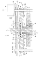
- FIG. 2 is an axial sectional view schematically showing the speed change mechanism according to the first embodiment of the present invention.
- FIG. 3 is an enlarged cross-sectional view showing a part (region D) of FIG.
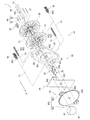
- FIG. 4 is an exploded perspective view showing one of the pinion sprockets of the speed change mechanism according to the first embodiment of the present invention.
- FIG. 5 is an exploded perspective view showing a main part of the speed change mechanism according to the first embodiment of the present invention.
- FIG. 5 is an exploded view of the main part corresponding to FIG. FIG.
- FIG. 6 is a side view of the main part showing one of the pinion sprockets of the speed change mechanism according to the first embodiment of the present invention, focusing on the gear teeth and the support part.
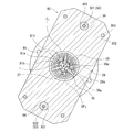
- FIG. 7 is a side view focusing on the movable disk of the speed change mechanism according to the first embodiment of the present invention.
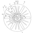
- FIG. 8 is a side view focusing on the fixed disk of the speed change mechanism according to the first embodiment of the present invention.
- FIG. 9 is a view for explaining the pinion sprocket and the guide rod that are moved in the radial direction by the fixed disk and the movable disk in the speed change mechanism according to the first embodiment of the present invention. In FIG. 9, the tangent circles become larger in the order of (a), (b), and (c). In FIG.
- FIG. 11 is an enlarged view of a main part showing a rotating part and a cam groove of the speed change mechanism according to the first embodiment of the present invention.
- FIG. 11 is an enlarged view of a main part showing an enlarged view CC of FIG.
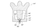
- FIG. 12 is an axial sectional view showing a modification of the speed change mechanism according to the first embodiment of the present invention.
- FIG. 13 is an axial cross-sectional view schematically showing the speed change mechanism according to the second embodiment of the present invention.
- FIG. 14 is an exploded perspective view showing one of the pinion sprockets of the speed change mechanism according to the second embodiment of the present invention.
- FIG. 15 is a radial cross-sectional view showing a modification of the speed change mechanism according to the second embodiment of the present invention.
- the transmission mechanism is applied to a vehicle transmission.
- This speed change mechanism is wound around one composite sprocket having a rotating shaft (input shaft) to which power is input, the other composite sprocket having a rotating shaft (output shaft) to which power is output, and these composite sprockets.
- Each composite sprocket has a plurality of pinion sprockets that mesh with the chain. These pinion sprockets move synchronously in the radial direction while maintaining an equal distance from the axis of the rotating shaft, and revolve around the axis of the rotating shaft.
- the power transmission is performed as a virtual line extending in the power transmission direction through the center in the width direction of the chain while being orthogonal to the axial direction and having the axial direction as the axis of the rotating shaft or a direction parallel to the axis.
- a line is defined, and each of the radial direction and the circumferential direction is determined with reference to the axis of the rotating shaft.
- the side close to the chain is referred to as the axially inner side
- the side separated from the chain is referred to as the axially outer side.
- one axial direction (hereinafter referred to as “one axial direction”) and the other (hereinafter referred to as “the other axial direction”) are determined based on the power transmission line. That is, one axial direction and the other axial direction are on opposite sides of the chain.
- the side close to the axis of the rotating shaft is called the radially inner side (or “inner side”), and the side separated from the axis of the rotating shaft is the outer side (or “outer side”). Side)).
- one of the radial directions hereinafter referred to as “one radial direction” and the other (hereinafter referred to as “the other radial direction”) are defined with reference to the axis of the rotation shaft. In other words, one radial direction and the other radial direction are on opposite sides of the axis of the rotation shaft.
- the advance side and the retard side are determined based on the direction in which the rotating shaft rotates in the speed change mechanism or the direction in which the pinion sprocket revolves around the axis of the rotating shaft.
- the advance side here refers to the side opposite to the revolving direction because it comes from the side where the rotational phase of the rotational drive source is fast (for example, the ignition timing in the internal combustion engine).
- the retard side means the side opposite to the advance side (revolution direction).
- one axial direction is indicated as “X1”
- the other axial direction is indicated as “X2”
- the radially inner side is indicated as “Y1”
- the radially outer side is indicated as “Y2”
- the retarded side is indicated as “Z1”.
- the advance side is indicated as “Z2”.
- a chain 4 is wound around two sets of composite sprockets 3 and 3.
- the chain 4 is not limited to the silent chain illustrated in FIG. 1, and a known chain such as a roller chain or a leaf chain can be used.
- the composite sprocket 3 is provided with a plurality of pinion sprockets 30 that mesh with the chain 4 and transmit power, and a plurality of guide rods 40 that guide (guide) the chain 4.
- the pinion sprocket 30 and the guide rod 40 are supported so as to rotate integrally with the rotary shaft 1, and revolve around the axis C 1 of the rotary shaft 1. Further, the pinion sprocket 30 and the guide rod 40 form an apparently large sprocket so as to form a vertex of a polygon when viewed from the axial direction.
- pinion sprockets 30 are arranged at equal intervals along the circumferential direction, and two guide rods 40 are arranged between the pinion sprockets 30 adjacent to each other in the circumferential direction. Sprockets are formed.
- the composite sprocket 3 is provided with a synchronous movement mechanism 50 (see FIG. 2) that moves the pinion sprocket 30 and the guide rod 40 in a radial direction while maintaining an equal distance from the axis C 1 of the rotating shaft 1. It has been.
- the synchronous movement mechanism 50 causes the pinion sprocket 30 and the guide rod 40 to move synchronously in the radial direction, thereby changing the outer diameter of the composite sprocket 3 and changing the gear ratio of the transmission mechanism.
- the outer diameter of the composite sprocket 3 means the diameter of a circle (hereinafter referred to as “contact circle”) A that contacts any of the pinion sprockets 30 from the outer periphery. Therefore, the outer diameter of the composite sprocket 3 not only corresponds to the radius of the tangent circle A, but also corresponds to the distance of the vertex of the polygon with respect to the axis C 1 of the rotating shaft 1, and the chain 4 is wound around. It corresponds to the radius.
- the pinion sprocket 30, the guide rod 40 and the chain 4 in FIG. 1 are shown by solid lines in which the input side contact circle A is the minimum and the output side contact circle A is the maximum, that is, the gear ratio is the lowest. On the other hand, a case where the input side contact circle A is the maximum and the output side contact circle A is the minimum, that is, the gear ratio is the highest, is indicated by a two-dot chain line.
- the synchronous movement mechanism 50 includes a fixed disk 10 that rotates integrally with the rotating shaft 1, a movable disk 20 that can rotate relative to the rotating shaft 1, and a fixed disk 10. And a relative rotation drive mechanism 60 for relatively rotating the movable disk 20.
- the relative rotation drive mechanism 60 is provided with two types of rotating portions 19 and 29 as a configuration of a rotating system that rotates around the axis C 1 .
- One of the rotating parts 19 and 29 is a fixed rotating part 19 that rotates integrally with the fixed disk 10, and the other is a movable rotating part 29 that rotates together with the movable disk 20.
- the relative rotation drive mechanism 60 is provided with an axial force transmission / reception system that transmits and receives force in the axial direction.
- the structure of the rotating system in the speed change mechanism includes a fixed system structure that is fixed so as to rotate integrally with the rotating shaft 1, a movable system structure that can rotate relative to the rotating shaft 1, and the axis of the rotating shaft 1. It is divided into revolving system configuration and revolves around C 1.
- a fixed disk 10 and a fixed rotating part 19 are provided as a fixed system structure
- a movable disk 20 and a movable rotating part 29 are provided as a movable system structure
- a pinion sprocket 30 and a guide rod 40 are provided as a revolving system structure.
- the fixed disk 10 and the fixed rotating part 19 which are each component of the fixed system and the movable disk 20 and the movable rotating part 29 which are each component of the movable system are concentric with the axis C 1 of the rotating shaft 1 and are power transmission lines. Symmetrically with respect to C 2 (see FIG. 2), they are arranged to face each other in one axial direction and the other axial direction. Further, the movable disk 20 and the fixed disk 10 are arranged in parallel from the inner side in the axial direction. That is, one of the axial disks and the other axially movable disk 20 are provided facing each other. On the inner side in the axial direction of the movable disk 20, the chain 4 is wound around the pinion sprocket 30 and the guide rod 40.
- rotating parts 19 and 29 are provided on the outer sides in the axial direction of the disks 10 and 20. These rotating portions 19 and 29 are provided concentrically with the axis C 1 of the rotating shaft 1, and the movable rotating portion 29 is disposed on the outer periphery of the fixed rotating portion 19.
- the configuration of the axial force transmission / reception system will be described.
- the pinion sprocket 30 is spaced in the order of the first pinion sprocket 301, the second pinion sprocket 302, the third pinion sprocket 303, the fourth pinion sprocket 304, the fifth pinion sprocket 305, and the sixth pinion sprocket 306. Arranged.
- the first pinion sprocket 301 is shown on the most retarded side of the pinion sprocket 30 that meshes with the chain 4.
- the first pinion sprocket 301 is roughly divided into a gear part 310 having gear teeth 311 that mesh with the chain 4 and a sprocket support part 330 that supports the gear part 310.
- These gear part 310 and sprocket support part 330 are provided separately.
- reference numerals are given to one member or part in the axial direction, and reference numerals of the other member or part in the axial direction are omitted.
- the gear part 310 is formed in a sector gear (fan gear) shape.
- the gear portion 310 is provided with a plurality of gear teeth 311 necessary for meshing with the chain 4 and a base portion 312 thereof. Further, the gear portion 310 has a sliding contact portion 320 slidably contacting the sprocket support portion 330 in the circumferential direction on the outer side in the axial direction (one axial direction and the other axial direction) with respect to the gear teeth 311 and the base portion 312. Provided.
- the gear teeth 311 and the base portion 312 are arranged on the inner side in the axial direction than the movable disk 20, and the sliding contact portion 320 is arranged on the inner side in the axial direction in the axial region where the movable disk 20 (see FIG. 2) is located.
- the gear teeth 311, the base 312, and the sliding contact portion 320 are integrally provided.
- the gear teeth 311 are provided so as to protrude outward in the radial direction.
- three gear teeth 311 are provided. These gear teeth 311 are arranged side by side along the circumferential direction.
- the base 312 is provided on the radially inner side with respect to the gear teeth 311.
- the base portion 312 is formed to have a longer axial dimension than the gear teeth 311, and each axial end portion protrudes from the gear teeth 311.
- a sliding contact portion 320 is coupled to each of the axial end portions of the base portion 312.
- the sliding contact portion 320 has a fan shape when viewed from the axial direction.
- the fan shape here means a shape surrounded by two radial lines and two arcs between them. One arc is arranged radially inside, and the other arc is arranged radially outside. These arcs are set along the circumferential direction. Therefore, the sliding contact portion 320 is formed with a pair of sliding contact surfaces (outer surfaces) 321 extending in the circumferential direction. Specifically, in the sliding contact portion 320, an outer sliding contact surface 322 is formed on the radially outer side, and an inner sliding contact surface 323 is formed on the radially inner side.
- the sliding contact portion 320 is provided with a housing portion 324 that houses a part of a return spring (gear urging member) 390 along the circumferential direction.
- a compression spring is used as the return spring 390.
- two types of accommodating portions 324 are provided: a retarded angle side accommodating portion 325 provided on the retarded angle side and an advanced angle side accommodating portion 326 provided on the advanced angle side.
- FIG. 4 illustrates an example in which one retard side accommodation portion 325 and two advance side accommodation portions 326 are provided in one axial direction. However, as shown on the other side in the axial direction, two retarded angle side accommodating portions and one advanced angle side accommodating portion may be provided.
- the retard angle accommodating portion 325 accommodates an advance bias spring (first spring) 391 that biases the gear portion 310 toward the advance angle side. Further, the advance angle side accommodating portion 326 accommodates a retard angle biasing spring (second spring) 392 that biases the gear portion 310 toward the retard angle side.
- the biasing force of the advance bias spring 391 and the bias force of the retard bias spring 392 are equal in a state where the sliding contact portion 320 is located at the center in the circumferential direction of a slot 352 described later.
- the sprocket support 330 is roughly divided into three in order from the outside in the axial direction: a fixed sprocket support 340, a movable sprocket support 350, and a connecting member 360.
- the fixed sprocket support portion 340 is disposed so as to overlap with the fixed disk 10 in the axial direction
- the movable sprocket support portion 350 is disposed so as to overlap with the movable disk 20 in the axial direction
- the connecting member 360 is connected to the movable disk 20. It is arrange
- the fixed sprocket support portion 340 and the movable sprocket support portion 350 are provided in one axial direction and the other axial direction, respectively, and one connecting member 360 is provided across the one axial direction and the other axial direction.
- the fixed sprocket support 340 and the movable sprocket support 350 are integrally coupled by a connecting member 360.
- Fixed sprocket support 340 is composed of a shaft portion 341 and the bearing 342, and both are disposed concentrically with the shaft center C 3.
- the shaft portion 341 protrudes outward in the axial direction from the movable sprocket support portion 350 and is provided in a cylindrical shape, and the bearing 342 is provided in a cylindrical shape on the outer periphery of the shaft portion 341.
- FIG. 4 illustrates a bearing 342 in which a large number of needle bearings are arranged on the inner periphery.
- the fixed sprocket support 340 is provided so that the radial position of the shaft portion 341 overlaps the radial position of the gear teeth 311. Furthermore, as illustrated in FIG. 6, the radial position where the gear teeth 311 mesh with the chain 4 and the radial position of the axial center C 3 of the shaft portion 341 and the bearing 342 coincide with each other. preferable.
- the movable sprocket support portion 350 is provided with a protruding portion 356 from the radially inner end of the main body 351 toward the radially inner side.
- the width (circumferential dimension) W 2 of the protrusion 356 is narrower than the width (circumferential dimension) W 1 of the main body 351.
- the protrusion 356 extends in the radial direction over a predetermined length (dimension in the radial direction) L with the width W 2 being constant.
- the main body 351 also extends in the radial direction with a constant width W 1 .
- a slot 352 for receiving the sliding contact portion 320 of the sprocket support 330 is recessed in the main body 351 on the inner side in the axial direction.
- the slot 352 has a sector shape when viewed from the axial direction.
- the fan shape formed by the slot 352 is formed in a shape corresponding to the fan shape formed by the sliding contact portion 320, and one arc is disposed on the radially inner side and the other arc is disposed on the radially outer side. Therefore, a pair of sliding contact surfaces (inner surface) 353 extending in the circumferential direction of the contact circle A is formed in the slot 352.
- an outer sliding contact surface 354 is formed on the radially outer side, and an inner sliding contact surface 355 is formed on the radially inner side. More specifically, the outer sliding contact surface 322 of the sliding contact portion 320 is in sliding contact with the radially inner side of the outer sliding contact surface 354, and the inner sliding contact surface 323 of the sliding contact portion 320 is slidable radially outward of the inner sliding contact surface 355. By making contact, the sliding contact portion 320 can slide in the slot 352.
- the sector shape formed by the slot portion 352 has a longer circumferential dimension (arc length) than the sector shape formed by the sliding contact portion 320. That is, since the central angle of the sector is larger in the slot portion 352 than in the slide contact portion 320, the advance side and the retard side (one and the other in the circumferential direction) of the slide contact portion 320 accommodated in the slot portion 352 Each has a space. In other words, the sliding contact portion 320 can slide only by the circumferential dimension of the space formed on the advance side and the retard side, and further sliding is limited.
- the protrusion 356 is provided with a fitting hole 357 into which the axial end of the connecting member 360 is fitted. Therefore, the projecting portions 356 of the movable sprocket support portion 350 in the one axial direction and the other in the axial direction are coupled by the coupling member 360.
- the first pinion sprocket 301 is provided with an allowance mechanism 370 that allows the gear portion 310 to move freely with respect to the sprocket support portion 330 and a gear portion 310 toward a predetermined reference phase with respect to the sprocket support portion 330.
- a gear biasing mechanism 380 for biasing is provided.
- the floating allowance mechanism 370 includes a slot portion 352 of the movable sprocket support portion 350 and a sliding contact portion 320 of the gear portion 310. This free movement allowance mechanism 370 allows free movement of the gear section 310 within a predetermined range with respect to a predetermined reference phase.
- the predetermined reference phase is a phase of the gear portion 310 in a state where the sliding contact portion 320 is disposed at the circumferential center of the slot portion 352. That is, a predetermined reference phase is set as a phase at which the gear unit 310 can move equally toward the advance side and the retard side. Further, the predetermined range is a range corresponding to the half teeth of the gear teeth 311 on each of the advance side and the retard side with respect to the predetermined reference phase. Therefore, if the gear unit 310 is positioned on the most retarded side or the most advanced side, the free movement of the gear unit 310 toward the advanced side or the retarded side is allowed up to one gear tooth 311.
- This predetermined range allows the circumferential dimension of the space formed on the advance side and the retard side with respect to the sliding contact portion 320 arranged in the slot 352, that is, sliding contact of the sliding contact portion 320 is allowed. It corresponds to the size. Therefore, if the sliding contact portion 320 arranged at the center in the circumferential direction of the slot portion 352 is used as a reference, the space on the advance side and the space on the retard side with respect to the sliding contact portion 320 are the gear teeth 311. Is set to a circumferential dimension corresponding to the half-tooth portion.
- the gear biasing mechanism 380 is provided with a return spring 390 in addition to the slot portion 352 of the movable sprocket support portion 350 and the sliding contact portion 320 of the gear portion 310.
- the gear urging mechanism 380 urges the gear unit 310 with the urging force of the return spring 390 toward the predetermined reference phase described above.
- the return spring 390 biases the sliding contact portion 320 toward the advance side by the advance bias spring 391 and biases the slide contact portion 320 toward the retard side by the retard bias spring 392.
- the gear portion 310 is urged from both the advance side and the retard side toward the predetermined reference phase.
- each of the guide rods 40 guide the chain 4 by bringing the track of the chain 4 to be wound closer to a circular track.
- the guide rod 40 does not mesh with the chain 4 and does not transmit power.
- each of the guide rods 40 is provided with a cylindrical guide member 42 on the outer periphery of the rod support portion 41.
- a rod support portion 41 protrudes from the guide member 42 at the axial end portion 40 a of the guide rod 40.
- the protruding rod support portion 41 is supported by the disks 10 and 20.
- the chain 4 contacts the axially outer side of the guide member 42.
- the guide rod 40 is roughly divided into a first guide rod 401 and a second guide rod 402.
- the first guide rod 401 always guides the chain 4 regardless of the radial position.
- the second guide rod 402 guides the chain 4 when the contact circle A is the largest, but does not guide the chain 4 when the contact circle A is the smallest.
- the second guide rod 402 is positioned on the radially inner side than the guide rod 401.
- the track of the chain 4 becomes closer to a perfect circle and the wrapping radius can be suppressed, but there is a risk of increasing manufacturing costs and weight. It is preferable to set in consideration of the above.
- the movable disk 20 is provided with two types of radial grooves 21 and 22 extending in the radial direction and two types of holes 25 and 26 radially inward of these radial grooves. These radial grooves 21 and 22 and holes 25 and 26 are formed through the movable disk 20 in the axial direction.
- One of the radial grooves 21, 22 is a movable radial groove 21 for a sprocket provided corresponding to each of the pinion sprockets 30 (the reference numeral is given only at one place), and the other corresponds to each of the guide rods 40.
- These movable radial grooves 21 and 22 are grooves for guiding the corresponding pinion sprocket 30 and guide rod 40. Therefore, the movable radial grooves 21 and 22 are provided along the radial movement path of the pinion sprocket 30 and the guide rod 40, respectively.
- one of the holes 25 and 26 is a through hole 25 (only one place is given a symbol) through which the connecting shaft 27 is inserted, and the other is a shaft hole 26 through which the rotary shaft 1 is inserted.
- Shaft hole 26 is provided on the axis C 1 and concentric rotary shaft 1, the through hole 25 is provided radially outward of the shaft hole 26.
- movable radial grooves 21 and 22 First, the movable radial grooves 21 and 22 will be described.
- the movable sprocket support 350 of the pinion sprocket 30 is inserted into the movable radial groove 21 for the sprocket.
- the rod support portion 41 of the guide rod 40 is inserted into the fixed radial groove 12 for the rod.
- the groove widths of the movable radial grooves 21 and 22 are set according to the width W 1 of the movable sprocket support 350 and the diameter of the rod support 41. Specifically, the groove width of the movable radial grooves 21 and 22 is slightly larger than the outer diameter of the corresponding support portions 350 and 41. Therefore, the support portions 350 and 41 can smoothly move along the movable radial grooves 21 and 22. These movable radial grooves 21 and 22 are linearly viewed from the axial direction. In particular, the rotation of the pinion sprocket 30 is prevented by inserting a movable sprocket support portion 350 (see FIG. 4) extending in the radial direction while keeping the widths W 1 and W 2 constant into the linear movable radial groove 21 for the sprocket. Prevention of rotation).
- the sprocket movable radial groove 21 is provided along the radial direction.
- a protruding groove 212 is provided so as to protrude from the radially inner end of the main body groove 211 toward the axial center C 1 and radially inward. That is, the protruding groove 212 is provided at the inner peripheral end 21 a of the sprocket movable radial groove 21.
- the groove width W 2 ′ of the protruding groove 212 is set to be narrower than the groove width W 1 ′ of the main body groove 211.
- the groove width W 1 of the main body groove 211 ' is substantially identical to the width W 1 of the main body portion 351, the groove width W 2 of the projecting groove 212' is substantially the same as the width W 2 of the projecting portion.
- the main body groove 211 groove width W 1 ' is slightly smaller towards the width W 1 of the main body portion 351 than similarly, the groove width W 2 of the projecting groove 212' of width W 2 of the projecting portion than Is slightly narrower. Therefore, the main body portion 351 can smoothly move (slide) in the main body groove 211, and the protruding portion 356 can enter and exit in the radial direction with respect to the protruding groove 212.
- the protruding groove 212 extends in the radial direction over a predetermined length (radial dimension) L while keeping the groove width W 2 ′ constant.
- the predetermined length L is set to be approximately the same as the predetermined length L (see FIG. 4) of the protrusion 356 in the movable sprocket support 350.
- the shape of the protruding groove 212 is formed in a shape corresponding to the protruding portion 356 of the movable sprocket support portion 350.
- the contact circle A is the smallest in the composite sprocket 3 on the input side, so that the movable pinion sprocket support 350 is positioned at the inner peripheral end 21a of the movable radial groove 21 for the sprocket.
- the protruding portion 356 of the movable pinion sprocket support portion 350 is located inside the protruding groove 212. Therefore, the protruding groove 212 and the protruding portion 356 are in contact with each other in a planar shape (a linear shape when viewed from the axial direction) over a predetermined length L along the radial direction.
- a circumferential force is transferred between the protruding groove 212 and the protruding portion 356.
- the main body groove 211 and the main body portion 351 come into contact with each other in a planar shape to transfer a circumferential force.
- the movable radial groove 22 for the rod is composed of a movable radial groove 23 for the first rod that supports the first guide rod 401 and a movable radial groove 24 for the second rod that supports the second guide rod 402. It is roughly divided into two.
- the connecting shaft 27 is inserted into the through hole 25. Therefore, the number (here, three) of through holes 25 (symbols are attached to only one place) corresponding to the number of the connecting shafts 27 are provided. These through holes 25 are arranged at equal intervals along the circumferential direction. The inner diameter of the through hole 25 is set to a size commensurate with the outer diameter of the connecting shaft 27.
- the shaft hole 26 is a shaft hole through which the rotary shaft 1 is inserted.
- the inner diameter of the shaft hole 26 is set to be slightly larger than the outer diameter of the rotating shaft 1.
- the rotary shaft 1 inserted through the shaft hole 26 is not coupled to the movable disk 20 and can rotate independently. In other words, the movable disk 20 can rotate relative to the rotating shaft 1.
- the movable rotating portion 29 is a cylindrical member disposed on the outer periphery of the fixed rotating portion 19.
- the movable rotating portion 29 is provided with a movable cam groove 29a extending in the axial direction.
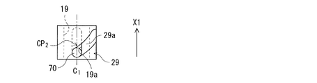
- the movable cam groove 29a as shown in FIG. 11, are bored so as to communicate the inside and outside of the cylindrical wall while being formed so as to intersect with the axis C 1 of the rotary shaft 1 when viewed from the radial direction .
- a plurality of movable cam grooves 29a are preferably arranged at equal intervals along the circumferential direction. For example, it may be provided in three positions as illustrated in FIG. 10, may be provided in two locations or four locations facing each other across the axis C 1 of the rotary shaft 1 as illustrated in FIG. 3 .
- the connecting shaft 27 extends in the axial direction. As shown in FIG. 3, the connecting shaft 27 is roughly divided into an axially outer first connecting portion 27a and an axially inner second connecting portion 27b.
- the first connecting portion 27 a is located in an axial region connecting the movable disk 20 and the movable rotating portion 29 in each of one axial direction and the other axial direction. Therefore, the movable disk 20 and the movable rotating part 29 are connected by the first connecting part 27a so as to rotate integrally.
- the second connecting portion 27b is located in an axial direction region that connects the one movable disk 20 in the axial direction and the other in the axial direction. Therefore, the pair of movable disks 20 are connected by the second connecting portion 27b so as to rotate integrally.
- the connecting shaft 27 has the first connecting portion 27a disposed in a region where the second connecting portion 27b extends in one axial direction and the other in the axial direction. It can be said that the connecting portion 27a and the second connecting portion 27b are integrally coupled.
- each of the axial ends of the connecting shaft 27 is fixed to the movable rotating portion 29 by bolts 28.
- a plurality of connecting shafts 27 are preferably arranged at equal intervals along the circumferential direction. For example, it may be provided at three places as illustrated in FIG. 1, FIG. 5, and FIG. 10, or two places facing each other across the axis C 1 of the rotating shaft 1 as illustrated in FIG. 2 and FIG. Or you may provide in four places.
- the connecting shaft 27 is arranged in a phase that does not interfere with the movable cam groove 29a (see FIGS. 5 and 10). However, for convenience of explanation, the movable cam groove 29a and the connecting shaft 27 are shown in FIGS. And the bolt 28 are shown in the same cross section.
- the fixed disk 10 As a configuration of the fixed system, a fixed disk 10 and a fixed rotating unit 19 are provided. [1-3-1. (Fixed disk) As shown in FIG. 8, the fixed disk 10 is provided with two types of radial grooves 11 and 12 extending in the radial direction, and two types of holes 15 and 16 radially inward of the radial grooves 11 and 12. It is done. These radial grooves 11 and 12 and holes 15 and 16 are formed so as to penetrate the fixed disk 10 in the axial direction.
- One of the radial grooves 11 and 12 is a fixed radial groove 11 for a sprocket provided corresponding to each of the pinion sprockets 30 (the reference numeral is given only at one place), and the other corresponds to each of the guide rods 40.
- This is a fixed radial groove 12 for a rod provided with a reference numeral only at one place.
- These fixed radial grooves 11 and 12 are grooves for guiding the corresponding pinion sprocket 30 and guide rod 40 in the same manner as the movable radial grooves 21 and 22. Accordingly, the fixed radial grooves 11 and 12 are provided along the radial movement paths of the pinion sprocket 30 and the guide rod 40, respectively.
- one of the holes 15 and 16 is a through hole 15 (only one part is given a symbol) through which the connecting shaft 27 is inserted, and the other is a shaft hole 16 into which the rotary shaft 1 is inserted.
- Shaft hole 16 is provided on the axis C 1 and concentric rotary shaft 1, the through hole 15 is provided radially outward of the shaft hole 16.
- each of the fixed radial grooves 11 and 12 is formed so as to intersect with each of the movable radial grooves 21 and 22 when viewed from the axial direction.
- the intersection hereinafter referred to as “disk intersection”
- CP 1 between the fixed radial grooves 11 and 12 and the movable radial grooves 21 and 22 is the most.
- disk intersection Located radially inward.
- the outer diameter of the fixed disk 10 and the outer diameter of the movable disk 20 overlap as viewed from the axial direction.
- FIG. 9 shows the outer diameter of the movable disk 20 rather than the outer diameter of the fixed disk 10. The diameter is shown slightly smaller.
- the fixed sprocket support 340 of the pinion sprocket 30 is inserted into the fixed radial groove 11 for the sprocket.
- the rod support portion 41 of the guide rod 40 is inserted into the fixed radial groove 12 for the rod.
- the groove widths of the fixed radial grooves 11 and 12 are set according to the diameters of the support portions 340 and 41. Specifically, the groove width of the fixed radial grooves 11 and 12 is slightly larger than the outer diameter of the corresponding support portions 340 and 41. Therefore, the support portions 340 and 41 can smoothly move (slide) along the fixed radial grooves 11 and 12.
- These fixed radial grooves 11 and 12 are inclined with respect to the radial direction so that the intersecting point CP 1 moves in the radial direction in accordance with the relative rotation of the fixed disk 10 and the movable disk 20, and viewed from the axial direction. It is formed in a curved shape.
- the fixed radial groove 12 for rods like the movable radial grooves 23 and 24 for rods, supports the first fixed rod radial grooves 13 on which the first guide rod 401 is supported and the second guide rod 402.
- the second rod is roughly divided into a fixed radial groove 14 for the second rod.
- the distance to the axis C 1 of the rotary shaft 1 from an outer peripheral end portion 13b of the first rod fixed radial grooves 13, the rotary shaft 1 from the inner peripheral end portion 14b of the second rod fixed radial grooves 14 The distance to the axis C 1 is equal.
- the fixed radial groove 14 for the second rod is inclined relative to the radial direction rather than the fixed radial groove 13 for the first rod. Is provided.
- the contact circle A is the maximum (the gear ratio is the highest)
- the chain 4 is By ensuring the number of guide rods 40 to be guided, fluctuations in the winding radius of the chain 4 can be suppressed. Therefore, power can be stably transmitted and generation of noise can be suppressed.
- the contact circle A is the minimum (the gear ratio is the lowest)
- the interference between the guide rods 40 is reliably avoided. As a result, the gear ratio can be increased especially toward the low side, and the ratio coverage can be ensured.
- the connecting shaft 27 is inserted into the through hole 15. Specifically, the first connecting portion 27 a of the connecting shaft 27 is inserted through the through hole 15. Therefore, the number of through holes 15 (three here) corresponding to the number of the connecting shafts 27 is provided. These through holes 15 are arranged at equal intervals along the circumferential direction.
- the through hole 15 is provided to extend in the circumferential direction by a phase that allows the movable disk 20 to rotate relative to the fixed disk 10. That is, the through hole 15 is a long hole along the circumferential direction.
- the connecting shaft 27 when the tangent circle A is the minimum (the transmission ratio is the lowest), the connecting shaft 27 is positioned at the circumferential end 1a in the through hole 15, and conversely, as shown in FIG. As shown in (c), when the contact circle A is the maximum (the transmission ratio is the highest), the connecting shaft 27 is positioned at the other end 15b in the circumferential direction in the through hole 15.
- the groove width (diameter direction dimension) of the through hole 15 is set larger than the outer diameter of the first connecting portion 27 a of the connecting shaft 27.
- the shaft hole 16 is a shaft hole into which the rotating shaft 1 is inserted.
- the inner diameter of the shaft hole 16 is set to a size commensurate with the outer diameter of the rotating shaft 1.
- the rotary shaft 1 inserted into the shaft hole 16 is integrally fixed to the fixed disk 10.
- the shaft hole 16 that is a perfect circle as viewed from the axial direction is illustrated.
- the concave and convex shapes corresponding to the shaft fixing hole and the rotating shaft are provided in the circumferential direction, so that the fixed disk 10 and the rotating shaft 1 are provided. You may comprise so that it may rotate integrally.
- the fixed rotating portion 19 is provided on a part of the rotating shaft 1.
- a portion of the rotating shaft 1 that is outside of the disks 10 and 20 in the axial direction functions as the fixed rotating portion 19.
- the fixed rotating portion 19 is provided with a fixed cam groove 19a extending in the axial direction.
- the fixed cam groove 19 a is recessed in parallel with the axis C 1 of the rotary shaft 1.
- the fixed cam groove 19a is formed so as to intersect with each of the movable cam grooves 29a when viewed from the radial direction.
- cam intersection portion The specific shape of the cam grooves 19a and 29a is such that, in the composite sprocket 3 on the input side, the intersection portion CP 2 between the fixed cam groove 19a and the movable cam groove 29a (hereinafter referred to as “cam intersection portion”) is axially inward. next (High side gear ratio him to toward the axially outer side) speed ratio Low side toward Similarly, the composite sprocket 3 on the output side, the gear ratio as the cam intersection CP 2 is directed axially inwardly It is set to be on the Low side.
- the location and number of the fixed cam groove 29a may be set according to the surrounding configuration and required specifications, and various shapes and numbers can be employed. .
- each of the two sets of composite sprockets 3 and 3 is independently provided with an axial force transmission / reception system.
- the configuration of the axial force transmission / reception system includes a cam roller 70 (see FIG. 2) inserted into the cam intersection CP 2 , and a transmission that transmits axial force to the cam roller 70.
- the axial movement mechanism 90 can be said to be a cam roller movement mechanism that moves the cam roller 70 in the axial direction by moving the shift fork 80 in the axial direction.
- the axial direction moving mechanism 90 is provided with a feed screw mechanism 91, an interlocking gear mechanism 95 that is linked to the feed screw mechanism 91, and a support 98 that supports the interlocking gear mechanism 95.
- the feed screw mechanism 91 is provided with a nut 94 that is screwed onto a screw shaft 93 that is rotated by an electric motor 92.
- a cam roller 70, a shift fork 80, and a nut 94 are provided so as to overlap with the rotary portions 19 and 29 in the axial direction.
- the support 98, the interlocking gear mechanism 95, and the electric motor 92 are provided in this order from the cam roller 70, the speed change fork 80, and the nut 94 outward in the axial direction.
- the cam roller 70, the speed change fork 80, the support 98, and the interlocking gear mechanism 95 are arranged symmetrically with respect to the power transmission line C 2 (see FIG. 2) as opposed to one of the axial direction and the other axial direction.
- the electric motor 92 is disposed only in one axial direction.
- the screw shaft 93 is provided through the interlocking gear mechanism 95, the support 98, and the speed change fork 80. Further, a guide shaft 993 (see FIG. 5) concentric with the axis C 4 of the counter spring 99 is attached.
- the counter springs 99 are arranged in one of the radial direction and the other in the radial direction. Specifically, a counter spring 99 and a guide shaft 993 are disposed at each of the four corners of the speed change fork 80 as viewed from the axial direction. As shown in FIGS. 2 and 3, the screw shaft 93 may be used (shared) as a guide shaft of the counter spring 99.
- the “movable disk 20”, “ “Fixed disk 10”, “rotating portions 19 and 29, cam roller 70, speed change fork 80 and nut 94”, “support 98”, and “interlocking gear mechanism 95” are provided in each of one axial direction and the other axial direction.
- An “electric motor 92” is provided on the outer side in the axial direction of the interlocking gear mechanism 95 in one axial direction.
- the configuration straddling one axial direction and the other axial direction is listed in the order of short axial dimension, “pinion sprocket 30 and guide rod 40”, “connection shaft 27”, “counter spring 99”, “guide shaft 993”, “screw” Axis 93 ".
- the pinion sprocket 30 and the guide rod 40 are disposed in an axial region that includes the one fixed disk 10 in the axial direction and the other fixed disk 10 in the axial direction and connects them.
- the connecting shaft 27 is disposed in an axial region connecting the axially one and the other axially movable movable unit 29.
- a counter spring 99 is disposed on the inner side in the axial direction between the first and second axial shifting forks 80, and the guide shaft 993 includes the axial one and the other axial shifting fork 80. Are arranged in an axial region connecting the two. Then, the screw shaft 93 is disposed in an axial region that includes the one interlocking gear mechanism 95 in the axial direction and the other interlocking gear mechanism 95 in the axial direction.
- the cam roller 70 and the shift fork 80 will be described first, followed by the axial movement mechanism 90 and the counter spring 99 in this order.
- cam roller 70 and the speed change fork 80 are displaced in the axial direction in order to rotate the movable system configuration relative to the fixed system configuration. Specifically, the cam roller 70 is pressed by the shift fork 80 moved in the axial direction, and the pressed cam roller 70 is displaced in the axial direction.
- the cam roller 70 (a reference numeral is attached to only one place) is configured by a shaft-like member extending in the radial direction.
- the cam roller 70 is inserted into each of the fixed cam groove 19a and the movable cam groove 29a in cam intersections CP 2. Further, the one end portion 70 a of the cam roller 70 is disposed so as to protrude radially outward from the movable rotating portion 29.
- the cam roller 70 inserted into the cam grooves 19 a and 29 a also rotates (revolves) around the axis C 1 .
- bearings are provided at locations where the radial regions overlap with the cam grooves 19a and 29a.
- the speed change fork 80 is a plate-like member parallel to the disks 10 and 20. 5 and 10 illustrate a speed change fork 80 having four corners as viewed from the axial direction.
- the speed change fork 80 is provided with a cam roller support portion 81 that supports a radially outer portion of the cam roller 70.
- the cam roller support portion 81 includes a rotation portion accommodation hole 811 for accommodating the rotation portions 19 and 29 on the radially inner side, and a groove portion 81 a that is recessed on the entire outer periphery in the radial direction with respect to the rotation portion accommodation hole 811.
- the inner diameter of the rotating part receiving hole 811 is set to be slightly larger than the outer diameter of the movable rotating part 29. Therefore, the rotating portions 19 and 29 can rotate on the radially inner side of the rotating portion receiving hole 811.
- the depth (diameter dimension) of the groove 81 a is set according to the protruding dimension (diameter dimension) of the one end 70 a of the cam roller 70. That is, an annular space having a slightly longer radial dimension than the projecting dimension of the cam roller 70 is formed as the groove 81a.
- the groove 81 a is provided with a rolling element 81 b that is in rolling contact with the cam roller 70.
- the some rolling element 81b is arrange
- ball bearings can be used in addition to the needle bearings illustrated in FIGS.
- the transmission fork 80 has a screw mechanism hole 801 through which the screw shaft 93 and the nut 94 of the feed screw mechanism 91 are disposed, and a shaft hole 802 into which the axial end of the guide shaft 993 is inserted. (See FIG. 10) are provided penetrating in the axial direction.
- the screw mechanism holes 801 are provided in one of the radial direction (upper right in FIGS. 5 and 10) and the other radial direction (lower left in FIGS. 5 and 10).
- the shaft holes 802 correspond to the arrangement of the counter springs 99, and are provided at the four corners of the speed change fork 80 here.
- the axial movement mechanism 90 is provided with a feed screw mechanism 91 that operates an interlocking gear mechanism 95 supported by a support 98.
- the feed screw mechanism 91 rotationally drives the screw shaft 93 by the electric motor 92, thereby moving the nut 94 screwed to the screw shaft 93 in the axial direction.
- the direction of the male screw is set to be opposite to each other at one site in the axial direction and the other site in the axial direction.
- the direction of the female screw is set to be opposite between the nut 94 on the one axial side and the nut 94 on the other side in the axial direction.
- a right-hand thread is formed in each of one axial portion of the screw shaft 93 and one axial nut 94, and conversely, the other axial portion of the screw shaft 93 and the other nut 94 axially.
- Each is formed with a left-hand thread.
- both the axial one nut and the other axial nut 94 move axially inward or axially outward.
- These nuts 94 are disposed in the screw mechanism hole 801 and are coupled (fixed) to the speed change fork 80.
- the speed change fork 80 disposed so as to face the one axial direction and the other axial direction is connected by the screw shaft 93 and the nut 84 of the axial movement mechanism 90.
- the screw shaft 93 is provided on each of one side in the radial direction and the other side in the radial direction. Specifically, one first screw shaft 931 in the radial direction and the second screw shaft 932 in the other radial direction are provided. The rotations of these screw shafts 931 and 932 are interlocked by an interlocking gear mechanism 95. Similarly, the nut 94 is also provided in each of one radial direction and the other radial direction.
- the interlocking gear mechanism 95 is provided with two types of gears 950 and 959.
- One of the two types of gears 950 and 959 is a pinion gear 950 that is provided concentrically with the axis C 5 of the screw shaft 93 and is coupled to rotate integrally with the screw shaft 93.
- the first pinion gear 951 is coupled to the axial end portion of the first screw shaft 931 and disposed on one radial side.
- the second pinion gear 952 is coupled to the axial end of the second screw shaft 932 and disposed on the other radial direction.
- the other of the two types of gears 950 and 959 is an idler gear 959 that is provided concentrically with the axis C 1 of the rotary shaft 1 and meshes with each of the pinion gears 951 and 952.
- the idler gear 959 has a bearing interposed between the rotary shaft 1 and rotates independently of the rotary shaft 1.
- the support 98 is a plate-like support member fixed to a transmission case (not shown).
- the support 98 is provided with two screw shaft holes 980 for supporting each of the screw shafts 93 to be inserted, and a rotation shaft hole 989 for supporting the rotary shaft 1 to be inserted.
- the screw shaft 93 is rotatably supported with respect to the screw shaft hole 980.
- the rotary shaft 1 is rotatably supported with respect to the rotary shaft hole 989.
- the support 98 is formed in a Z shape when viewed in the axial direction.
- the elements in one radial direction and the other radial direction such as two screw shaft holes 980, screw shafts 931, 932, and pinion gears 951, 952 are shown in the same cross section. .
- the counter spring 99 is an urging member that applies an initial urging force to the speed change fork 80 in a direction opposite to the expansion / contraction bias direction.
- the expansion / contraction bias direction means a direction in which the contact circle A naturally expands / contracts when power is transmitted.
- This expansion / contraction bias direction is a direction in which the contact circle A is reduced in diameter on the input-side composite sprocket 3, and conversely, in the output-side composite sprocket 3, the contact circle A is expanded in diameter. The reason is as follows.
- the pinion sprocket 30 that meshes with the chain 4 on the most retarded side mainly bears power transmission. Therefore, during power transmission, tension is applied to the chain 4 wound around the input-side composite sprocket 3 in a wider range (winding region) than the chain 4 wound around the output-side composite sprocket 3.
- a force for reducing the diameter of the composite sprocket 3 on the input side hereinafter referred to as “diameter reduction force” works, and conversely, a force for expanding the diameter of the composite sprocket 3 on the output side ( Hereinafter, this is referred to as “diameter expansion force”.
- the tension acts only on the retarded side, that is, just before the pinion sprocket 3 is detached from the chain 4, so that the diameter reducing force due to the tension is very small, but the diameter expanding due to the centrifugal force. Power works strongly. Since the centrifugal force is proportional to the square of the number of rotations, a large diameter expansion force works particularly when the output side rotates at a high speed. However, the diameter expansion force due to the centrifugal force is smaller than the diameter reduction force generated in the composite sprocket on the input side.
- the contact circle A tends to reduce the diameter by the diameter reducing force, and conversely, in the composite sprocket 3 on the output side, the contact circle A tries to expand the diameter by itself.
- the cam intersection CP 2 is set as the speed ratio toward the axially inner side becomes the Low side, the cam roller 70 and the shift provided cam intersections CP 2 A diameter reducing force acts as a force for moving the fork 80 inward in the axial direction.
- the cam intersection CP 2 is set as the speed ratio toward the axially inner side becomes the Low side, the cam roller 70 and the shift provided cam intersections CP 2 A diameter expansion force acts as a force for moving the fork 80 inward in the axial direction.
- the expansion / contraction bias direction is a direction toward the inner side in the axial direction in the composite sprocket 3 on the input side, and similarly, a direction toward the inner side in the axial direction in the composite sprocket 3 on the output side. Therefore, a compression spring that urges outward in the axial direction is used as the counter spring 99 in the composite sprocket 3 on the input side. Similarly, the counter spring 99 in the composite sprocket 3 on the output side faces outward in the axial direction. A biasing compression spring is used.
- a guide shaft 993 is attached to the counter spring 99.
- a shift fork 80 is provided on the guide shaft 993 so as to be movable in the axial direction.
- the axial dimension of the guide shaft 993 is set to be longer than the axial dimension of the shifting forks 80 positioned on the outermost side in the axial direction and shorter than the dimension of interference (contact) with each of the supports 98.
- the speed change fork 80 coupled to each of the nuts 94 moves inward or outward in the axial direction. That is, the shifting fork 80 in the one axial direction and the other in the axial direction are displaced so as to be close to or separated from each other while being held by the nuts 94 provided in each of the one radial direction and the other radial direction.
- the driving reaction force that moves the shifting fork 80 in the axial direction and the driving reaction force that moves the shifting fork 80 in the other axial direction act in opposite directions via the screw shafts 931 and 932. Is offset by
- an initial urging force is applied to the shift fork 80 by the counter spring 99 in the direction opposite to the expansion / contraction bias direction.
- the shifting fork 80 in the composite sprocket 3 on the input side has a diameter reducing force in the direction in which the expansion / contraction biasing direction is inward in the axial direction
- the counter spring 99 has an initial urging force in the axially outward direction. Is granted.
- the shifting fork 80 in the composite sprocket 3 on the output side is subjected to an expanding force in a direction in which the expansion / contraction bias direction is directed inward in the axial direction, whereas an initial urging force that is directed outward in the axial direction by the counter spring 99. Is granted. Therefore, at least a part of the diameter reducing force and the diameter expanding force in the expansion / contraction bias direction are offset by the counter spring 99.
- the gear allowance mechanism 370 is allowed to idle in the circumferential direction by the amount of phase deviation. Specifically, the gear teeth 311 are pressed toward the advance side or the retard side by the chain 4 that is out of phase. Therefore, the sliding contact part 320 provided integrally with the gear tooth 311 to be pressed is also pressed to the advance side or the retard side. The slidable contact portion 320 thus pressed slides inside the slot portion 352 while expanding and contracting the return spring 390. For example, when the gear teeth 311 are pressed toward the advance side, the sliding contact portion 320 slides inside the slot 352 toward the advance side.
- the retarding biasing spring 392 contracts to increase the biasing force toward the retarding side with respect to the sliding contact portion 320, and the advancement biasing spring 391 extends to move toward the advancement side with respect to the sliding contact portion.
- the urging power of is weakened. That is, the biasing force to the predetermined reference phase with respect to the sliding contact portion 320 is increased.
- a rotational moment that rotates the pinion sprocket 30 around the axis C 3 of the fixed sprocket support 340 is generated by power transmission between the pinion sprocket 30 and the gear teeth 311.
- a first input which is a circumferential component of this rotational moment, works from the meshing position of the gear teeth 311 to the chain 4 toward the advance side.
- This first input is transmitted to the fixed sprocket support 340 via the base 312, the sliding contact portion 320 and the movable sprocket support 330. That is, the first input is transmitted radially outward from the meshing position of the chain 4 and the gear teeth 311 and then radially outward.
- a drag force acting from the wall surface of the sprocket fixed radial groove 11 supporting the fixed sprocket support 340 toward the retard side acts.
- the composite sprocket 3 on the input side consists of the transmission torque of the pinion sprocket 30 is particularly large, the rotation moment about the axis C 3 of the fixed sprocket support 340 is large possibility There is.
- This rotational moment works to rotate the pinion sprocket 30.
- the main body part 351 and the protrusion part 356 of the movable pinion sprocket support part 350 act so as to be inclined with respect to the radial direction.
- the protrusion portion 356 and the protrusion groove 212 are in a surface shape to contact with each other in the circumferential direction.
- the resistance against the rotational moment from the wall surface of the main body groove 211 acting on the main body portion 351 acts on the protruding portion 356.
- the movable pinion sprocket support 350 is firmly received by the wall surface of the movable radial groove 21 for the sprocket, and the rotation of the pinion sprocket 30 is reliably suppressed.
- the gear teeth 311 are disengaged from the chain 4 and the meshing is released.
- the gear teeth 311 urged by the gear urging mechanism 380 form a predetermined reference phase.
- the first pinion sprocket 301 is provided with a gear portion 310 having gear teeth 311 that mesh with the chain 4 on the radially inner side in a sector gear shape. Therefore, the radial dimension of the first pinion sprocket 301 can be made smaller on the inner side in the radial direction of the chain 4 than a structure in which gear teeth are provided on the entire outer periphery as in Patent Document 1. Therefore, it is possible to sufficiently secure a movable region inward of the first pinion sprocket 301 in the radial direction. Therefore, sufficient ratio coverage can be ensured.
- the gear allowance mechanism 370 is allowed to idle in the circumferential direction by the amount of phase deviation.
- the gear teeth 311 are disengaged from the chain 4 and disengaged, they are urged by the gear urging mechanism 380 to form a predetermined reference phase.
- the gear teeth 311 can move freely both on the advance side and on the retard side. Therefore, the gear teeth 311 that mesh with the chain 4 after that can surely move according to the phase shift. Therefore, the running of the chain 4 and the tooth skipping with respect to the gear teeth 311 can be suppressed, and the meshing property of the first pinion sprocket 301 with respect to the chain 4 can be improved.
- the gear urging mechanism 380 includes, as the return spring 390, an advance angle urging spring 391 that urges the gear part 310 toward the advance side, and a lag angle that urges the gear part 310 toward the retard side. Since the biasing spring 392 is provided, the gear unit 310 is reliably biased toward a predetermined reference phase. Therefore, the gear part 310 in which the meshing of the gear teeth 311 with the chain 4 is released can be reliably positioned at a predetermined reference phase. Therefore, it is possible to reliably secure the allowance for the gear portion 311 of the gear portion 310 when the gear teeth 311 mesh with the chain 4.
- the floating allowance mechanism 370 has a structure in which main parts such as the sliding contact part 320 and the return spring 390 are accommodated in the movable sprocket support part 350, and these main parts are shafts with respect to the gear teeth 311. It is arranged outside in the direction. Therefore, the structure on the radially inner side of the gear part 310 is simplified, the movable range to the radially inner side of the first pinion sprocket 301 is secured, and the ratio coverage can be reliably secured.
- the return spring 390 is disposed in the space provided on each of the advance side and the retard side of the sliding contact portion 320 in the slot portion 352 of the floating allowance mechanism 370, the sliding contact portion 320.
- the return spring 390 can be arranged by utilizing the space in which the slidably move. In other words, the return spring 390 can be accommodated in a space provided as an allowance for the sliding contact portion 320.
- the sliding contact portion 320 and the slot portion 352 of the free movement allowance mechanism 370 are provided in the main body portion 351 wider than the protruding portion 356 in the movable sprocket support portion 350, the advance side and the retard angle in the slot portion 352 are provided. Side space can be secured.
- the size of the return spring 390 arranged in these spaces and the degree of freedom for setting the urging force can be improved. If the return spring 390 having a large urging force is used, the gear unit 310 can be urged more reliably to a predetermined reference phase.
- the predetermined range in which the free movement of the gear unit 310 is allowed by the free movement allowance mechanism 370 is a half tooth of the gear teeth 311 from the predetermined reference phase, the range in which the phase between the gear teeth 311 and the chain 4 can be shifted. (All range of phase shift) can be handled. Therefore, the meshing property of the first pinion sprocket 301 with respect to the chain 4 can be further improved.
- the axial force transmission / reception system including the transmission fork 80 and the axial movement mechanism 90 is provided independently for each of the two sets of composite sprockets 3 and 3. Therefore, in each of the composite sprockets 3 and 3, an axial movement force can be applied independently, and the above-described effects of reducing the burden on each component of the axial force transfer system and improving the durability can be obtained. it can.
- the shifting fork 800 includes an input-side rotating portion receiving hole 812 for storing the rotating portions 19 and 29 of the input-side composite sprocket 300 and an output-side rotating portion for storing the rotating portions 19 and 29 of the output-side composite sprocket 300.
- a receiving hole 813 is provided.
- Input rotary portion receiving holes 812 is provided on the axis C 10 concentric with the rotation shaft 100 to which power is inputted, likewise, the output-side rotation unit housing hole 813, the axis of the rotary shaft 100 to which power is input It provided mind C 10 concentrically.
- the speed change fork 800 is provided with a screw mechanism hole 820 through which the screw shaft 930 and the nut 940 of the feed screw mechanism 910 are disposed.
- FIG. 12 illustrates an example in which three screw mechanism holes 820 are provided at intervals along the power transmission line C 20 .
- the first screw mechanism hole 821 on the side separated from the composite sprocket 300 on the output side and between the composite sprocket 300 on the input side and the composite sprocket 300 on the output side.
- Three screw mechanism holes 820 are formed, that is, a two-screw mechanism hole 822 and a third screw mechanism hole 823 on the output-side composite sprocket 300 that is separated from the input-side composite sprocket 300.
- a feed screw mechanism 910 In the axial movement mechanism 900, a feed screw mechanism 910, an interlocking gear mechanism 96, and a support 97 are provided across the input side and output side composite sprockets 300, 300, and a counter spring (counter biasing member) 990 is provided on the input side and It is provided on both the composite sprockets 300 and 300 on the output side.
- each of the screw shafts 930 In the feed screw mechanism 910, each of the screw shafts 930 is arranged concentrically with the corresponding screw mechanism hole 820, and similarly, each of the nuts 940 is arranged concentrically with the corresponding screw mechanism hole 820.
- an electric motor 920 is provided at one end of a screw shaft 930 provided in the second screw mechanism hole 822.
- the interlocking gear mechanism 96 is provided with a pinion gear (first gear) 960 coupled to rotate integrally with each of the screw shafts 930 and an idler gear (second gear) 965 that meshes with each of the pinion gears 960. .
- the pinion gear 960 is coupled to the first pinion gear 961 coupled to the screw shaft 930 inserted through the first screw mechanism hole 821 and the screw shaft 930 inserted through the second screw mechanism hole 822.
- a second pinion gear 962 and a third pinion gear 963 coupled to a screw shaft 930 inserted through the third screw mechanism hole 823 are provided.
- a first idler gear 966 that meshes with each of the first pinion gear 961 and the second pinion gear 962 and a second idler gear 967 that meshes with each of the second pinion gear 962 and the third pinion gear 963 are provided.
- a first idler gear 966 is arranged concentrically with the axis C 10 of the rotating shaft 100 to which power is input
- a second idler gear 967 is arranged concentrically with the axis C 10 of the rotating shaft 100 to which power is output. ing.
- the support 97 is provided with a screw shaft hole 970 for supporting each of the screw shafts 930 via a bearing (not shown) and the like, and a rotation shaft hole 979 through which each of the rotation shafts 100 is inserted.
- the counter spring 990 is disposed between the speed change fork 800.
- the input-side composite sprocket 300 is separated from the output-side composite sprocket 300, and between the input-side composite sprocket 300 and the output-side composite sprocket 300.
- An example is shown in which counter springs 990 are arranged at three locations on the output-side composite sprocket 300 and the side separated from the input-side composite sprocket 300.
- both the combined sprockets 300, 300 on the input side and the output side can be mechanically interlocked by the interlocking gear mechanism 96 to expand and contract each circle A. . Therefore, there is no need to individually control the input-side and output-side electric motors 92, and the shift controllability can be improved.
- a diameter reducing force in this case, an axial movement force toward the inside in the axial direction
- a diameter expansion force here, an axial movement force toward the inside in the axial direction
- These diameter-reducing force and diameter-enlarging force are forces that move one axially and the other axially-shifting fork 800 in the axial direction, and the reaction force of these forces is transmitted via the screw shaft 930 of the axially moving mechanism 900. Offset. For example, when the magnitude of the diameter reducing force is different from the magnitude of the diameter expanding force, a load that twists between the input side portion and the output side portion acts on the speed change fork 800, but it is counteracted as described above. The torsional load is reduced by canceling the force.
- the diameter reducing force and the diameter expanding force are shared by the respective components of the axial force transmission / reception system provided in one of the axial direction and the other of the axial direction. Therefore, the durability of the transmission mechanism can be reliably improved.
- the speed change mechanism of the second embodiment differs from the speed change mechanism of the first embodiment described above in the arrangement of the counter spring and the structure of the pinion sprocket. Except for the points described here, the configuration is the same as that of the first embodiment described above. About these structures, the same code
- the counter spring 99 ′ is arranged on the outer side in the axial direction (side away from the chain 4) with respect to the speed change fork 80.
- the counter spring 99 is disposed so as to straddle one axial direction and the other axial direction, whereas in the second embodiment, the counter spring is disposed on the axially outer side with respect to the shifting fork 80.
- 99 ' is arrange
- a counter spring 99 ′ is provided between the speed change fork 80 and the support 98 along the axial direction.
- the gear ratio is set to become the low side as the cam intersection point CP 2 ′ moves outward in the axial direction. Therefore, a diameter reducing force acts as a force for moving the cam roller 70 and the shift fork 80 provided at the cam crossing point CP 2 ′ outward in the axial direction.
- the gear ratio is set to become the lower side as the cam intersection point CP 2 ′ moves outward in the axial direction. Therefore, a diameter expansion force acts as a force for moving the cam roller 70 and the shift fork 80 provided at the cam crossing point CP 2 ′ outward in the axial direction.
- the expansion / contraction bias direction is a direction toward the outside in the axial direction in the composite sprocket 3 ′ on the input side, and similarly, a direction toward the outside in the axial direction in the composite sprocket 3 on the output side.
- a compression spring that urges inward in the axial direction is used as the counter spring 99 'in the composite sprocket 3' on the input side.
- the counter spring 99 'in the composite sprocket 3' on the output side is used in the axial direction.
- a compression spring that urges inward is used.
- the sliding contact portion 320 is provided in the gear portion 310 and the slot portion 352 is provided in the sprocket support portion 330, whereas as shown in FIG.
- a slot 313 ′ is provided in the gear part 310 ′, and a sliding contact part 360 ′ inserted into the slot 313 ′ is connected to the sprocket support part 330 ′.
- the pinion sprocket 30 ' will be described in detail.
- the pinion sprocket 30 ' is roughly divided into a gear part 310' having gear teeth 311 'meshing with the chain 4 (see Fig. 13) and a sprocket support part 330' for supporting the gear part 310 '.
- These gear portion 310 ′ and sprocket support portion 330 ′ are provided separately.
- reference numerals are given to one member or part in the axial direction, and reference numerals of the other member or part in the axial direction are omitted. Subsequently, the pinion sprocket support portion 330 ′ and the gear portion 310 ′ will be described in this order.
- FIG. 14 illustrates a movable sprocket support portion 350 ′ in the form of a key member that extends in the radial direction with a constant width (circumferential dimension).
- Two holes 351 'and 352' arranged in the radial direction on the inner side in the axial direction are recessed in the movable sprocket support portion 350 '.
- the radially outer side is a fitting hole 351 ′ into which the axial end of the sliding contact portion 360 ′ is fitted.
- the sliding contact portion 360 ′ has a fan shape when viewed from the axial direction.
- the sector formed by the sliding contact portion 360 ′ has the same shape as the sector formed by the sliding contact portion 320 of the first embodiment.
- the sliding contact portion 360 ′ has a pair of sliding contact surfaces (outer surfaces) 361 ′ extending in the circumferential direction including an outer sliding contact surface 362 ′ on the radially outer side and an inner sliding contact surface 363 ′ on the radially inner side.
- the sliding contact portion 360 ′ is provided with an accommodating portion 365 ′ that accommodates a return spring (gear urging member) 390 ′ along the circumferential direction.
- a compression spring is used as the return spring 390 '.
- two types of accommodating portions 365 ′ which are a retarded angle accommodating portion 366 ′ provided on the retarded angle side and an advanced angle side accommodating portion 367 ′ provided on the advanced angle side, are recessed.
- the retard angle side accommodating portion 366 ′ accommodates an advance angle biasing spring (first spring) 391 ′ that biases the gear portion 310 ′ toward the advance angle side.
- the advanced angle side accommodating portion 367 ′ accommodates a retarded angle biasing spring (second spring) 392 ′ that biases the gear portion 310 ′ toward the retarded angle side.
- the retard side accommodation portion 366 ′ and the advance side accommodation portion 367 ′ are arranged in this order from the power transmission line C 2 ′ (see FIG.
- the accommodation portion is based on the power transmission line C 2 ′.
- 365 ' is arranged symmetrically.
- the sliding contact portion 360 ′ is fitted into the fitting hole 351 ′ of the movable sprocket support portion 350 ′ at one end in the axial direction and at the other end in the axial direction. That is, the slidable contact portion 360 ′ connects the movable sprocket support portion 350 ′ on one axial direction and the other axial direction.
- the gear portion 310 ′ is disposed on the inner side in the axial direction than the movable disk 20 (see FIG. 13).
- the gear portion 310 ′ is provided with a base portion 312 ′ on the radially inner side of the gear teeth 311 ′. These gear teeth 311 ′ and the base 312 ′ are provided integrally.
- the base 312 ' is provided with a slot 313' penetrating in the axial direction.
- the sliding contact portion 360 ′ is inserted into the slot portion 313 ′.
- the slot 313 ' has a sector shape when viewed from the axial direction.
- the sector formed by the slot 313 ′ has the same shape as the sector of the slot 352 of the first embodiment.
- a pair of slidable contact surfaces (inner surface) 314 ′ including a radially outer slidable contact surface 315 ′ and a radially inner slidable contact surface 316 ′ extend in the circumferential direction in the slot 313 ′. .
- the outer slidable contact surface 362 ′ of the slidable contact portion 360 ′ is in slidable contact with the radially inner side of the outer slidable contact surface 315 ′, and the inner side of the slidable contact portion 360 ′ is radially outward of the inner slidable contact surface 316 ′.
- the sliding contact surface 363 ' is in sliding contact so that the sliding contact portion 360' can slide in the slot 313 '.
- the sector shape formed by the slot 313 ′ has a longer circumferential dimension (arc length) than the sector shape formed by the sliding contact portion 360 ′, and the advance side of the sliding contact portion 360 ′ and A space is formed on the retard side.
- the pinion sprocket 30 ′ includes a movement allowance mechanism 370 ′ that allows the gear portion 310 ′ to freely move with respect to the sprocket support portion 330 ′, and a gear portion toward a predetermined reference phase with respect to the sprocket support portion 330 ′.
- the floating allowance mechanism 370 ′ is constituted by a slot 313 ′ of the gear portion 310 ′ and a sliding contact portion 360 ′ of the sprocket support portion 330 ′.
- the gear urging mechanism 380 ′ includes a gear portion via a protrusion 399 ′ in addition to the slot 313 ′ of the gear portion 310 ′, the sliding contact portion 360 ′ of the sprocket support portion 330 ′, and the return spring 390 ′.
- a leaf spring 395 ' is provided to bias 310' to a predetermined reference phase.
- the protrusion 399 ′ is provided to protrude radially inward from the gear portion 310 ′.
- a pin-like protrusion 399 ' is mounted in a radially inner recess in the base 312' of the gear part 310 'with the radially inner end projecting therefrom.
- the protrusion 399 ' is urged toward a predetermined reference phase by a pair of leaf springs 395' arranged side by side in the circumferential direction.
- the leaf spring 395 ′ arranged on the advance side urges the projection 399 ′ toward the retard side
- the leaf spring 395 ′ arranged on the retard side moves the projection 399 ′ on the advance side.
- the groove portion 313 ′ is provided with a pair of sliding contact surfaces 314 ′ along the circumferential direction, and the sliding contact portion 360 ′ is in sliding contact with the sliding contact surface 314 ′ of the groove portion 313 ′.
- a surface 361 ' is provided. That is, the slot 313 ′ into which the sliding contact portion 360 ′ is inserted is disposed on the inner side in the axial direction than the movable disk 20. Therefore, the structure of the sprocket support 330 'can be simplified.
- the width of the sprocket movable radial groove into which the movable sprocket support 350 ′ having a simple structure is inserted is increased. Can be suppressed. Therefore, the interval between the grooves in the movable disk 20 can be reliably ensured.
- the gear urging mechanism 380' is provided with a leaf spring 395 'that urges the gear 310', so that the gear 310 'is urged toward a predetermined reference phase with certainty. can do.
- the meshing property between the gear portion 310 ′ and the chain 4 can be further improved.
- the plunger 368 ′′ is attached to the slot 313 ′′ so that the ball 369 ′′ protrudes and retracts from the inner sliding contact surface 316 ′′.
- This ball 369 ′′ is biased radially outward by the plunger 368 ′′.
- the plunger 368 ′′ has a position where the ball 369 ′′ is engaged with the most recessed portion (the radially outermost portion) of the recess 364 ′′ with the gear portion 310 ′′ in a predetermined reference phase. Arranged.
- the radially inner side of the plunger 368 ′′ projects from the base 312 ′′ of the gear portion 310 ′′.
- the concave portion 364 ′′ is formed so as to be shallower as it is separated from the predetermined reference phase toward the advance side or the retard side.
- the “shallowness of the concave portion 364 ′′” herein refers to the inner side described above in the second embodiment. It means the distance at which the concave portion 364 ′′ is spaced radially outward with respect to the sliding contact surface 363 ′.
- the fixed disk and the movable disk may be arranged side by side in the axial direction.
- the slot portion and the gear portion are arranged inside the radial groove in the fixed disk.
- the transmission mechanism may be configured as a continuously variable transmission mechanism in which the gear ratio is changed continuously (steplessly), or by displacing the radial positions of the pinion sprockets 30 and 30 ′ stepwise. You may comprise as a stepped transmission with which a gear ratio changes in steps.
Landscapes
- Engineering & Computer Science (AREA)
- General Engineering & Computer Science (AREA)
- Mechanical Engineering (AREA)
- Transmissions By Endless Flexible Members (AREA)
- Transmission Devices (AREA)
Abstract
変速機構のピニオンスプロケット(30)には、チェーン(4)と噛み合うギヤ歯(311)を有するセクターギヤ形状のギヤ部(310)と、ギヤ部(310)を支持する支持部(350)と、複合スプロケット(3)の周方向に沿う所定の範囲内で支持部(350)に対してギヤ部(310)が遊動することを許容する遊動許容機構(370)と、支持部(350)に対する所定の基準位相に向けてギヤ部(310)を付勢するギヤ付勢部材(390)を有するギヤ付勢機構(380)と、が設けられる。
Description
本発明は、入力側および出力側のそれぞれで回転軸の軸心に対して等距離を維持しながら径方向に可動に支持されて公転(回転軸と一体に回転)する複数のスプロケットによって形成される見かけ上の大きなスプロケットをなす複合スプロケットと、これらの複合スプロケットに巻き掛けられたチェーンとによって動力を伝達する変速機構に関する。
従来、プライマリプーリとセカンダリプーリとに駆動ベルトが巻き掛けられた変速機が開発されている。この変速機では、動力の入力される回転軸と動力の出力される回転軸とのそれぞれに設けられたプーリにおいて可動シーブに推力が付与されることで、各プーリと駆動ベルトとの間に摩擦力が発生する。この摩擦力によって、プーリと駆動ベルトとの間で動力が伝達される。
そのため、変速機において大きな動力が伝達される際には、推力を増大させて摩擦力を確保することが必要となる。その際、推力を発生させるポンプやモータといった動力源の負荷が上昇することでエネルギー消費の増加を招くおそれがあり、また、構造的に滑りが発生する箇所では摩擦損失が増大するおそれがある。
そのため、変速機において大きな動力が伝達される際には、推力を増大させて摩擦力を確保することが必要となる。その際、推力を発生させるポンプやモータといった動力源の負荷が上昇することでエネルギー消費の増加を招くおそれがあり、また、構造的に滑りが発生する箇所では摩擦損失が増大するおそれがある。
そこで、上記の推力や摩擦力を用いずに、スプロケットとチェーンとの噛み合いによって動力を伝達する変速機構が開発されている。
このような変速機構の一つとして、入力側および出力側のそれぞれに、同一半径位置を保ちながら径方向へ移動可能な複数の小さなスプロケット(以下、「ピニオンスプロケット」という)を配設し、これらの複数のピニオンスプロケットで見かけ上の大きなスプロケット(以下、「複合スプロケット」という)を形成し、これらの複合スプロケットに跨って巻き掛けられたチェーンによって動力を伝達するとともに入出力間の速度比(変速比)を変更する機構が提案されている。この変速機構では、それぞれの複合スプロケットを形成する複数のピニオンスプロケットが、動力の入力される回転軸または動力の出力される回転軸の軸心に対して等距離を維持しながら径方向に可動であって、回転軸と一体に回転するように支持され、回転軸の軸心を中心に回転(公転)する。
このような変速機構の一つとして、入力側および出力側のそれぞれに、同一半径位置を保ちながら径方向へ移動可能な複数の小さなスプロケット(以下、「ピニオンスプロケット」という)を配設し、これらの複数のピニオンスプロケットで見かけ上の大きなスプロケット(以下、「複合スプロケット」という)を形成し、これらの複合スプロケットに跨って巻き掛けられたチェーンによって動力を伝達するとともに入出力間の速度比(変速比)を変更する機構が提案されている。この変速機構では、それぞれの複合スプロケットを形成する複数のピニオンスプロケットが、動力の入力される回転軸または動力の出力される回転軸の軸心に対して等距離を維持しながら径方向に可動であって、回転軸と一体に回転するように支持され、回転軸の軸心を中心に回転(公転)する。
変速時には、ピニオンスプロケットが径方向に沿って変位することで、複合スプロケットが拡縮径して、変速比が変更される。そのため、周方向に隣接するピニオンスプロケット間におけるチェーンの巻掛長が連続的に変動し、複合スプロケットがなす見かけ上の歯数も連続的に変動する。この場合、チェーンの巻掛長や複合スプロケットがなす見かけ上の歯数の変動分は、ピニオンスプロケットとチェーンとのバックラッシュやガタの分だけしか吸収されず、ピニオンスプロケットに対するチェーンの乗り上げや歯飛びといった噛合性の低下を招くおそれがある。
かかる不具合に関し、たとえば特許文献1には、ピニオンスプロケットとチェーンとの噛合性を向上させる機構が開示されている。
具体的には、ピニオンスプロケットにおいて、内周に設けられた支持軸に対して外周に設けられたギヤ歯の回転(自転)を所定の範囲内で許容する回転許容機構が提案されている。この回転許容機構には、ギヤ歯の内周壁(あるいは支持軸の外周壁)と一体に回転するキー部材と、支持軸の外周壁(あるいはギヤ歯の内周壁)に形成されるとともにキー部材が回転方向に遊びをもって係合するキー溝とが設けられる。したがって、キー溝に対するキー部材の遊びの範囲内で支持軸に対するギヤ歯の回転が許容され、チェーンの位相に対してピニオンスプロケットのギヤ歯の位相を合わせることができる。
さらに、支持軸に対する所定の基準位相に向けてギヤ歯を付勢するギヤ付勢機構も提案されている。このギヤ付勢機構には、キー溝の回転方向中立位置に向けてキー部材を付勢するC型リングが設けられる。したがって、ピニオンスプロケットのギヤ歯がチェーンに噛み合っていないときには、進角方向および遅角方向の何れにもギヤ歯の回転代が確保され、チェーンに対するピニオンスプロケットの噛合性を向上させることができる。
具体的には、ピニオンスプロケットにおいて、内周に設けられた支持軸に対して外周に設けられたギヤ歯の回転(自転)を所定の範囲内で許容する回転許容機構が提案されている。この回転許容機構には、ギヤ歯の内周壁(あるいは支持軸の外周壁)と一体に回転するキー部材と、支持軸の外周壁(あるいはギヤ歯の内周壁)に形成されるとともにキー部材が回転方向に遊びをもって係合するキー溝とが設けられる。したがって、キー溝に対するキー部材の遊びの範囲内で支持軸に対するギヤ歯の回転が許容され、チェーンの位相に対してピニオンスプロケットのギヤ歯の位相を合わせることができる。
さらに、支持軸に対する所定の基準位相に向けてギヤ歯を付勢するギヤ付勢機構も提案されている。このギヤ付勢機構には、キー溝の回転方向中立位置に向けてキー部材を付勢するC型リングが設けられる。したがって、ピニオンスプロケットのギヤ歯がチェーンに噛み合っていないときには、進角方向および遅角方向の何れにもギヤ歯の回転代が確保され、チェーンに対するピニオンスプロケットの噛合性を向上させることができる。
ところで、上述した変速機構のように、ピニオンスプロケットの全外周にギヤ歯が設けられる構造では、ギヤ歯のうちチェーンと噛み合う箇所は一部であるにもかかわらず噛み合いに貢献しない多数のギヤ歯がチェーンに対して径方向内側に存在する。そのため、ピニオンスプロケットの径方向内側への可動範囲が抑えられ、ピニオンスプロケットが最も径方向内側に位置するときの複合スプロケットの外径が大きくなるおそれがある。よって、レシオカバレッジが制限される。このことから、チェーンと噛み合わない部分を取り除いて、ピニオンスプロケットをセクターギヤ形状に形成することが考えられる。
しかしながら、セクターギヤ形状のピニオンスプロケットには、上述した回転許容機構やギヤ付勢機構をそのまま適用することができず、チェーンに対する噛合性を向上させるうえで改善の余地がある。
しかしながら、セクターギヤ形状のピニオンスプロケットには、上述した回転許容機構やギヤ付勢機構をそのまま適用することができず、チェーンに対する噛合性を向上させるうえで改善の余地がある。
本発明は、上記のような課題に鑑み創案されたものであり、変速機構に関し、レシオカバレッジを確保したうえでチェーンに対するピニオンスプロケットの噛合性を向上させることを目的の一つとする。
(1)本発明の変速機構は、動力が入力または出力される回転軸と、前記回転軸の径方向に可動に支持される複数のピニオンスプロケットと、前記回転軸の軸心から等距離を維持させながら前記複数のピニオンスプロケットを前記径方向に同期させて移動させる同期移動機構と、を有する複合スプロケットを二組と、前記二組の複合スプロケットに巻き掛けられたチェーンとを備え、前記複数のピニオンスプロケットの何れもを囲み且つ前記複数のピニオンスプロケットの何れにも接する接円の半径を変更することによって変速比を変更する。
前記ピニオンスプロケットは、前記チェーンと噛み合うギヤ歯を有するセクターギヤ形状のギヤ部と、前記ギヤ部を支持する支持部と、前記複合スプロケットの周方向に沿う所定の範囲内で前記支持部に対して前記ギヤ部が遊動することを許容する遊動許容機構と、前記支持部に対する所定の基準位相に向けて前記ギヤ部を付勢するギヤ付勢部材を有するギヤ付勢機構と、を備える。
前記ピニオンスプロケットは、前記チェーンと噛み合うギヤ歯を有するセクターギヤ形状のギヤ部と、前記ギヤ部を支持する支持部と、前記複合スプロケットの周方向に沿う所定の範囲内で前記支持部に対して前記ギヤ部が遊動することを許容する遊動許容機構と、前記支持部に対する所定の基準位相に向けて前記ギヤ部を付勢するギヤ付勢部材を有するギヤ付勢機構と、を備える。
(2)前記ギヤ付勢部材は、前記周方向のうち一方に前記ギヤ部を付勢する第一ギヤ付勢部材と、前記周方向のうち他方に前記ギヤ部を付勢する第二ギヤ付勢部材とを有することが好ましい。
(3)前記遊動許容機構には、前記ギヤ部および前記支持部の何れか一方において、前記周方向に沿った一対の内表面を有する溝穴部が設けられ、また、前記ギヤ部および前記支持部の何れか他方において、前記周方向の一方および他方のそれぞれに空間をおいて前記溝穴部の内部に収容され、前記溝穴部に対応する形状に形成され前記内表面と摺接する摺接部が設けられることが好ましい。
(4)さらに、前記ギヤ付勢部材は、前記空間に配置され、前記摺接部を付勢することが好ましい。
(3)前記遊動許容機構には、前記ギヤ部および前記支持部の何れか一方において、前記周方向に沿った一対の内表面を有する溝穴部が設けられ、また、前記ギヤ部および前記支持部の何れか他方において、前記周方向の一方および他方のそれぞれに空間をおいて前記溝穴部の内部に収容され、前記溝穴部に対応する形状に形成され前記内表面と摺接する摺接部が設けられることが好ましい。
(4)さらに、前記ギヤ付勢部材は、前記空間に配置され、前記摺接部を付勢することが好ましい。
(5)前記同期移動機構は、前記支持部が挿入されるとともに前記径方向に延びる複数の固定放射状溝が形成され、前記回転軸と一体に回転する固定ディスクと、前記回転軸の軸方向から視て前記固定放射状溝のそれぞれと交差する交差箇所に前記支持部が挿入されるとともに前記径方向に延びる複数の可動放射状溝が形成され、前記固定ディスクに対して同心に配置され且つ相対回転可能な可動ディスクと、を備えることが好ましい。さらに、前記溝穴部および前記摺接部は、前記固定ディスクおよび前記可動ディスクのうち前記チェーンに近い側のディスクにおける前記固定放射状溝または前記可動放射状溝の内部に配置され、前記溝穴部は、前記支持部に設けられ、前記摺接部は、前記ギヤ部に設けられることが好ましい。
(6)または、前記同期移動機構は、前記支持部が挿入されるとともに前記径方向に延びる複数の固定放射状溝が形成され、前記回転軸と一体に回転する固定ディスクと、前記回転軸の軸方向から視て前記固定放射状溝のそれぞれと交差する交差箇所に前記支持部が挿入されるとともに前記径方向に延びる複数の可動放射状溝が形成され、前記固定ディスクに対して同心に配置され且つ相対回転可能な可動ディスクと、を備えることが好ましい。さらに、前記固定ディスクおよび前記可動ディスクそれぞれは、前記ギヤ歯に対して前記軸方向の一方および他方の少なくとも何れかに並設され、前記溝穴部および前記摺接部は、前記ギヤ歯に対して前記複合スプロケットの内周側に設けられ、前記溝穴部は、前記ギヤ部に設けられ、前記摺接部は、前記支持部に設けられることが好ましい。
(6)または、前記同期移動機構は、前記支持部が挿入されるとともに前記径方向に延びる複数の固定放射状溝が形成され、前記回転軸と一体に回転する固定ディスクと、前記回転軸の軸方向から視て前記固定放射状溝のそれぞれと交差する交差箇所に前記支持部が挿入されるとともに前記径方向に延びる複数の可動放射状溝が形成され、前記固定ディスクに対して同心に配置され且つ相対回転可能な可動ディスクと、を備えることが好ましい。さらに、前記固定ディスクおよび前記可動ディスクそれぞれは、前記ギヤ歯に対して前記軸方向の一方および他方の少なくとも何れかに並設され、前記溝穴部および前記摺接部は、前記ギヤ歯に対して前記複合スプロケットの内周側に設けられ、前記溝穴部は、前記ギヤ部に設けられ、前記摺接部は、前記支持部に設けられることが好ましい。
(7)前記ギヤ部は、前記複合スプロケットの内周側に向けて突出した突部を有し、前記ギヤ付勢部材は、前記突部を付勢することが好ましい。
(8)前記ギヤ付勢機構は、前記ギヤ部および前記支持部の何れか一方に設けられて前記所定の基準位相から進角側または遅角側に離隔するにつれて浅く凹設された凹部と、前記ギヤ部および前記支持部の何れか他方に設けられて前記凹部に突起部を付勢して係止する係止部と、を有することが好ましい。
(9)前記所定の範囲は、前記周方向の一方および他方それぞれに前記ギヤ歯の半歯分の範囲であることが好ましい。
(8)前記ギヤ付勢機構は、前記ギヤ部および前記支持部の何れか一方に設けられて前記所定の基準位相から進角側または遅角側に離隔するにつれて浅く凹設された凹部と、前記ギヤ部および前記支持部の何れか他方に設けられて前記凹部に突起部を付勢して係止する係止部と、を有することが好ましい。
(9)前記所定の範囲は、前記周方向の一方および他方それぞれに前記ギヤ歯の半歯分の範囲であることが好ましい。
本発明の変速機構によれば、セクターギヤ形状に形成されたギヤ部によってレシオカバレッジが確保され、そのうえで、遊動許容機構およびギヤ付勢機構によって噛合性を向上させることができる。
図面を参照して、本発明の変速機構に関する実施の形態を説明する。たとえば、本変速機構は車両用変速機に適用される。
この変速機構は、動力の入力される回転軸(入力軸)を有する一方の複合スプロケットと、動力の出力される回転軸(出力軸)を有する他方の複合スプロケットと、これらの複合スプロケットに巻き掛けられて一方から他方の複合スプロケットに動力を伝達するチェーンと、を備えている。各複合スプロケットは、チェーンと噛み合う複数のピニオンスプロケットを有する。これらのピニオンスプロケットは、回転軸の軸心から等距離を維持しながら径方向に同期して移動し、また、回転軸の軸心まわりに公転する。
この変速機構は、動力の入力される回転軸(入力軸)を有する一方の複合スプロケットと、動力の出力される回転軸(出力軸)を有する他方の複合スプロケットと、これらの複合スプロケットに巻き掛けられて一方から他方の複合スプロケットに動力を伝達するチェーンと、を備えている。各複合スプロケットは、チェーンと噛み合う複数のピニオンスプロケットを有する。これらのピニオンスプロケットは、回転軸の軸心から等距離を維持しながら径方向に同期して移動し、また、回転軸の軸心まわりに公転する。
以下の実施形態では、回転軸の軸心あるいはこの軸心に平行な方向を軸方向とし、軸方向に直交するとともにチェーンの幅方向中心を通って動力伝達方向に延びる仮想的な線として動力伝達線を定め、回転軸の軸心を基準に径方向および周方向のそれぞれを定める。
軸方向については、チェーンに対して近接する側を軸方向内側と呼び、チェーンに対して離隔する側を軸方向外側と呼ぶ。さらに、動力伝達線を基準として、軸方向の一方(以下、「軸方向一方」という)および他方(以下、「軸方向他方」という)を定める。すなわち、軸方向一方と軸方向他方とがチェーンを挟んで互いに反対側にある。
軸方向については、チェーンに対して近接する側を軸方向内側と呼び、チェーンに対して離隔する側を軸方向外側と呼ぶ。さらに、動力伝達線を基準として、軸方向の一方(以下、「軸方向一方」という)および他方(以下、「軸方向他方」という)を定める。すなわち、軸方向一方と軸方向他方とがチェーンを挟んで互いに反対側にある。
径方向については、回転軸の軸心に対して近接する側を径方向内側(あるいは「内周側」)と呼び、回転軸の軸心に対して離隔する側を径方向外側(あるいは「外周側」)と呼ぶ。さらに、回転軸の軸心を基準として、径方向の一方(以下、「径方向一方」という)および他方(以下、「径方向他方」という)を定める。すなわち、径方向一方と径方向他方とが回転軸の軸心を挟んで互いに反対側にある。
周方向については、変速機構において回転軸が回転する方向あるいはピニオンスプロケットが回転軸の軸心まわりに公転する方向を基準に進角側および遅角側を定める。ここでいう進角側とは、回転駆動源の回転位相が早い側であること(たとえば内燃機関における点火時期)に由来することから、公転する方向とは逆側を意味する。なお、遅角側は、進角側とは反対側(公転する方向)を意味する。
図面では、軸方向一方を「X1」と示し、軸方向他方を「X2」と示し、径方向内側を「Y1」と示し、径方向外側を「Y2」と示し、遅角側を「Z1」と示し、進角側を「Z2」と示す。
図面では、軸方向一方を「X1」と示し、軸方向他方を「X2」と示し、径方向内側を「Y1」と示し、径方向外側を「Y2」と示し、遅角側を「Z1」と示し、進角側を「Z2」と示す。
〔I.第一実施形態〕
以下、第一実施形態にかかる変速機構について説明する。
[1.構成]
まず、変速機構の構成を説明する。
図1に示すように、変速機構では、二組の複合スプロケット3,3にチェーン4が巻き掛けられている。このチェーン4としては、図1に例示するサイレントチェーンに限らず、ローラチェーンやリーフチェーンといった公知のものを用いることができる。
以下、第一実施形態にかかる変速機構について説明する。
[1.構成]
まず、変速機構の構成を説明する。
図1に示すように、変速機構では、二組の複合スプロケット3,3にチェーン4が巻き掛けられている。このチェーン4としては、図1に例示するサイレントチェーンに限らず、ローラチェーンやリーフチェーンといった公知のものを用いることができる。
この変速機構では、入力側の複合スプロケット3(図1では右方に示す)から出力側の複合スプロケット3(図1では左方に示す)にチェーン4を介して回転動力が伝達される。
入力側の複合スプロケット3には、動力の入力される回転軸1が設けられている。また、出力側の複合スプロケット3には、動力の出力される回転軸1が設けられている。これらの複合スプロケット3,3は、動力の伝達方向の違い(即ち、動力の伝達方向が入力側か出力側かの違い)を除いてそれぞれ同様に構成されている。そこで、主に入力側の複合スプロケット3の構成を説明する。
入力側の複合スプロケット3には、動力の入力される回転軸1が設けられている。また、出力側の複合スプロケット3には、動力の出力される回転軸1が設けられている。これらの複合スプロケット3,3は、動力の伝達方向の違い(即ち、動力の伝達方向が入力側か出力側かの違い)を除いてそれぞれ同様に構成されている。そこで、主に入力側の複合スプロケット3の構成を説明する。
複合スプロケット3には、回転軸1のほか、チェーン4と噛み合って動力を伝達する複数のピニオンスプロケット30と、チェーン4を案内(ガイド)する複数のガイドロッド40とが設けられる。ピニオンスプロケット30およびガイドロッド40は、回転軸1と一体に回転するように支持され、回転軸1の軸心C1を中心に公転する。また、ピニオンスプロケット30およびガイドロッド40は、軸方向から視て多角形の頂点をなすようにして、見かけ上の大きなスプロケットを形成する。ここでは、周方向に沿って等間隔に六つのピニオンスプロケット30が配置され、周方向に隣接するピニオンスプロケット30の間のそれぞれに二本のガイドロッド40が配置されて、十八角形の仮想的なスプロケットが形成される。
さらに、複合スプロケット3には、回転軸1の軸心C1から等距離を維持させながらピニオンスプロケット30およびガイドロッド40を径方向に同期させて移動させる同期移動機構50(図2参照)が設けられている。この同期移動機構50によって、ピニオンスプロケット30およびガイドロッド40が径方向に同期して移動することで、複合スプロケット3の外径が変動し、変速機構の変速比が変更される。
複合スプロケット3の外径とは、ピニオンスプロケット30の何れにも外周から接する円(以下、「接円」という)Aの直径を意味する。そのため、複合スプロケット3の外径は、接円Aの半径に対応するのはもちろん、回転軸1の軸心C1に対する多角形の頂点の距離に対応しており、また、チェーン4の巻き掛け半径に対応している。
図1のピニオンスプロケット30およびガイドロッド40ならびにチェーン4は、入力側の接円Aが最小であって出力側の接円Aが最大、即ち、変速比が最Lowの状態のものを実線で示し、反対に、入力側の接円Aが最大であって出力側の接円Aが最小、即ち、変速比が最Highの状態のものを二点鎖線で示す。
図1のピニオンスプロケット30およびガイドロッド40ならびにチェーン4は、入力側の接円Aが最小であって出力側の接円Aが最大、即ち、変速比が最Lowの状態のものを実線で示し、反対に、入力側の接円Aが最大であって出力側の接円Aが最小、即ち、変速比が最Highの状態のものを二点鎖線で示す。
図2および図5に示すように、同期移動機構50には、回転軸1と一体に回転する固定ディスク10と、回転軸1に対して相対回転可能な可動ディスク20と、固定ディスク10に対して可動ディスク20を相対回転駆動する相対回転駆動機構60と、が設けられる。
相対回転駆動機構60には、軸心C1まわりに回転する回転系の構成として二種の回転部19,29が設けられている。回転部19,29のうち一方は、固定ディスク10と一体に回転する固定回転部19であり、他方は、可動ディスク20と一体に回転する可動回転部29である。そのほか、相対回転駆動機構60には、軸方向に力を授受する軸方向力授受系の構成が設けられている。
相対回転駆動機構60には、軸心C1まわりに回転する回転系の構成として二種の回転部19,29が設けられている。回転部19,29のうち一方は、固定ディスク10と一体に回転する固定回転部19であり、他方は、可動ディスク20と一体に回転する可動回転部29である。そのほか、相対回転駆動機構60には、軸方向に力を授受する軸方向力授受系の構成が設けられている。
変速機構における回転系の構成は、回転軸1と一体に回転するように固定される固定系の構成と、回転軸1に対して相対回転可能な可動系の構成と、回転軸1の軸心C1まわりに公転する公転系の構成とに大別される。固定系の構成として、固定ディスク10および固定回転部19が設けられ、可動系の構成として、可動ディスク20および可動回転部29が設けられ、公転系の構成として、ピニオンスプロケット30およびガイドロッド40が設けられる。
固定系の各構成である固定ディスク10および固定回転部19ならびに可動系の各構成である可動ディスク20および可動回転部29は、回転軸1の軸心C1と同心であって、動力伝達線C2(図2参照)を基準として対称に軸方向一方および軸方向他方のそれぞれに対向して配置される。
また、軸方向内側から可動ディスク20,固定ディスク10の順に並設されている。すなわち、軸方向一方および軸方向他方の可動ディスク20が向かい合って設けられている。可動ディスク20の軸方向内側では、チェーン4がピニオンスプロケット30およびガイドロッド40に巻き掛けられている。
また、軸方向内側から可動ディスク20,固定ディスク10の順に並設されている。すなわち、軸方向一方および軸方向他方の可動ディスク20が向かい合って設けられている。可動ディスク20の軸方向内側では、チェーン4がピニオンスプロケット30およびガイドロッド40に巻き掛けられている。
さらに、ディスク10,20の軸方向外側に二種の回転部19,29が設けられる。これらの回転部19,29は、回転軸1の軸心C1と同心に設けられ、固定回転部19の外周に可動回転部29が配置される。
以下の説明では、回転系の構成を公転系の構成,可動系の構成,固定系の構成の順に説明した後に、軸方向力授受系の構成を述べる。
以下の説明では、回転系の構成を公転系の構成,可動系の構成,固定系の構成の順に説明した後に、軸方向力授受系の構成を述べる。
〔1-1.公転系の構成〕
上述したように、回転軸1の軸心C1まわりに公転する公転系の構成として、ピニオンスプロケット30およびガイドロッド40が設けられる。なお、説明の便宜のために図2および図3では、ピニオンスプロケット30やガイドロッド40を同断面に示している。
〔1-1-1.ピニオンスプロケット〕
図1に示すように、ここでは六つのピニオンスプロケット30が設けられている。具体的には、第一ピニオンスプロケット301,第二ピニオンスプロケット302,第三ピニオンスプロケット303,第四ピニオンスプロケット304,第五ピニオンスプロケット305,第六ピニオンスプロケット306の順に、ピニオンスプロケット30が間隔をおいて配置される。なお、図1では、チェーン4と噛み合うピニオンスプロケット30のうち最も遅角側に第1ピニオンスプロケット301を示している。
上述したように、回転軸1の軸心C1まわりに公転する公転系の構成として、ピニオンスプロケット30およびガイドロッド40が設けられる。なお、説明の便宜のために図2および図3では、ピニオンスプロケット30やガイドロッド40を同断面に示している。
〔1-1-1.ピニオンスプロケット〕
図1に示すように、ここでは六つのピニオンスプロケット30が設けられている。具体的には、第一ピニオンスプロケット301,第二ピニオンスプロケット302,第三ピニオンスプロケット303,第四ピニオンスプロケット304,第五ピニオンスプロケット305,第六ピニオンスプロケット306の順に、ピニオンスプロケット30が間隔をおいて配置される。なお、図1では、チェーン4と噛み合うピニオンスプロケット30のうち最も遅角側に第1ピニオンスプロケット301を示している。
これらのピニオンスプロケット301,302,303,304,305,306は、配置箇所が異なる点を除いて、同様に構成されている。そこで、第一ピニオンスプロケット301に着目して説明する。
図4に示すように第一ピニオンスプロケット301は、チェーン4と噛み合うギヤ歯311を有するギヤ部310と、ギヤ部310を支持するスプロケット支持部330と、の二つに大別される。これらのギヤ部310とスプロケット支持部330とは別体に設けられている。なお、図4では、軸方向一方の部材や部位に符号を付し、軸方向他方の部材や部位の符号は省略する。
図4に示すように第一ピニオンスプロケット301は、チェーン4と噛み合うギヤ歯311を有するギヤ部310と、ギヤ部310を支持するスプロケット支持部330と、の二つに大別される。これらのギヤ部310とスプロケット支持部330とは別体に設けられている。なお、図4では、軸方向一方の部材や部位に符号を付し、軸方向他方の部材や部位の符号は省略する。
〈ギヤ部〉
ギヤ部310は、セクターギヤ(扇形歯車)形状に形成されている。このギヤ部310には、チェーン4との噛み合いに必要な複数のギヤ歯311とその基部312とが設けられている。また、ギヤ部310には、これらのギヤ歯311および基部312に対して軸方向外側のそれぞれ(軸方向一方および軸方向他方)に、スプロケット支持部330と周方向に摺接する摺接部320が設けられる。ギヤ歯311および基部312は、可動ディスク20よりも軸方向内側に配置され、摺接部320は、可動ディスク20(図2参照)の位置する軸方向領域のうち軸方向内側に配置される。これらのギヤ歯311,基部312,摺接部320は一体に設けられる。
ギヤ部310は、セクターギヤ(扇形歯車)形状に形成されている。このギヤ部310には、チェーン4との噛み合いに必要な複数のギヤ歯311とその基部312とが設けられている。また、ギヤ部310には、これらのギヤ歯311および基部312に対して軸方向外側のそれぞれ(軸方向一方および軸方向他方)に、スプロケット支持部330と周方向に摺接する摺接部320が設けられる。ギヤ歯311および基部312は、可動ディスク20よりも軸方向内側に配置され、摺接部320は、可動ディスク20(図2参照)の位置する軸方向領域のうち軸方向内側に配置される。これらのギヤ歯311,基部312,摺接部320は一体に設けられる。
ギヤ歯311は、径方向外側に突出して設けられる。ここでは、3個のギヤ歯311が設けられる。これらのギヤ歯311は、周方向に沿って並んで配置される。
基部312は、ギヤ歯311に対して径方向内側に設けられる。この基部312は、ギヤ歯311よりも軸方向寸法が長く形成され、軸方向端部のそれぞれがギヤ歯311から突出する。基部312の軸方向端部のそれぞれには、摺接部320が結合されている。
基部312は、ギヤ歯311に対して径方向内側に設けられる。この基部312は、ギヤ歯311よりも軸方向寸法が長く形成され、軸方向端部のそれぞれがギヤ歯311から突出する。基部312の軸方向端部のそれぞれには、摺接部320が結合されている。
摺接部320は、軸方向から視て扇形をなす。ここでいう扇形とは、二本の半径線とこれらの間の二つの円弧とで囲まれる形状を意味する。一方の円弧は径方向内側に配置され、他方の円弧は径方向外側に配置される。これらの円弧は、周方向に沿って設定されている。そのため、摺接部320には、周方向に延びる一対の摺接面(外表面)321が形成される。具体的には、摺接部320において、径方向外側に外側摺接面322が形成され、径方向内側に内側摺接面323が形成される。
さらに、摺接部320には、リターンスプリング(ギヤ付勢部材)390の一部を収容する収容部324が周方向に沿って設けられている。ここでは、リターンスプリング390として圧縮スプリングが用いられている。
具体的には、遅角側に設けられた遅角側収容部325と進角側に設けられた進角側収容部326との二種の収容部324が凹設されている。図4では、一つの遅角側収容部325と二つの進角側収容部326とが軸方向一方に設けられるものを例示する。ただし、軸方向他方に示すように、二つの遅角側収容部と一つの進角側収容部とが設けられてもよい。
具体的には、遅角側に設けられた遅角側収容部325と進角側に設けられた進角側収容部326との二種の収容部324が凹設されている。図4では、一つの遅角側収容部325と二つの進角側収容部326とが軸方向一方に設けられるものを例示する。ただし、軸方向他方に示すように、二つの遅角側収容部と一つの進角側収容部とが設けられてもよい。
遅角側収容部325には、ギヤ部310を進角側に付勢する進角付勢用スプリング(第一スプリング)391が収容される。また、進角側収容部326には、ギヤ部310を遅角側に付勢する遅角付勢用スプリング(第二スプリング)392が収容される。
ここでは、後述する溝穴部352の周方向中央に摺接部320が位置した状態において、進角付勢用スプリング391の付勢力と遅角付勢用スプリング392の付勢力とが等しくなるように設定される。そのため、周方向の力(外力)がギヤ部310に働いていなければ、スプリング391,392の付勢力(内力)が打ち消しあって、溝穴部352の周方向中央に摺接部320が位置する。あるいは、ギヤ部310が進角側または遅角側に変位するほど、溝穴部352の周方向中央へ向けて摺接部320を付勢する力が大きくなる。つまり、外力の解放時に、溝穴部352の周方向中央に摺接部320の位置が収束するように、リターンスプリング390が摺接部320を付勢する。
ここでは、後述する溝穴部352の周方向中央に摺接部320が位置した状態において、進角付勢用スプリング391の付勢力と遅角付勢用スプリング392の付勢力とが等しくなるように設定される。そのため、周方向の力(外力)がギヤ部310に働いていなければ、スプリング391,392の付勢力(内力)が打ち消しあって、溝穴部352の周方向中央に摺接部320が位置する。あるいは、ギヤ部310が進角側または遅角側に変位するほど、溝穴部352の周方向中央へ向けて摺接部320を付勢する力が大きくなる。つまり、外力の解放時に、溝穴部352の周方向中央に摺接部320の位置が収束するように、リターンスプリング390が摺接部320を付勢する。
〈スプロケット支持部〉
スプロケット支持部330は、軸方向外側から順に、固定スプロケット支持部340,可動スプロケット支持部350,連結部材360の三つに大別される。固定スプロケット支持部340は、固定ディスク10と軸方向位置が重複して配置され、可動スプロケット支持部350は、可動ディスク20と軸方向位置が重複して配置され、連結部材360は、可動ディスク20よりも軸方向内側に配置される。すなわち、固定スプロケット支持部340および可動スプロケット支持部350が軸方向一方および軸方向他方のそれぞれに設けられ、一つの連結部材360が軸方向一方および軸方向他方に跨って設けられる。これらの固定スプロケット支持部340,可動スプロケット支持部350は、連結部材360によって一体に結合される。
スプロケット支持部330は、軸方向外側から順に、固定スプロケット支持部340,可動スプロケット支持部350,連結部材360の三つに大別される。固定スプロケット支持部340は、固定ディスク10と軸方向位置が重複して配置され、可動スプロケット支持部350は、可動ディスク20と軸方向位置が重複して配置され、連結部材360は、可動ディスク20よりも軸方向内側に配置される。すなわち、固定スプロケット支持部340および可動スプロケット支持部350が軸方向一方および軸方向他方のそれぞれに設けられ、一つの連結部材360が軸方向一方および軸方向他方に跨って設けられる。これらの固定スプロケット支持部340,可動スプロケット支持部350は、連結部材360によって一体に結合される。
固定スプロケット支持部340は、軸部341および軸受け342で構成され、両者が軸心C3と同心に設けられている。軸部341は、可動スプロケット支持部350から軸方向外側に突出して円柱状に設けられ、軸受け342は、軸部341の外周で円筒状に設けられる。図4では、多数のニードルベアリングが内周に配置された軸受け342を例示している。
この固定スプロケット支持部340では、ギヤ歯311の径方向位置に対して軸部341の径方向位置が重複するように設けられる。更に言えば、図6に例示するように、チェーン4に対してギヤ歯311が噛合する径方向位置と軸部341および軸受け342の軸心C3の径方向位置とが一致していることが好ましい。
この固定スプロケット支持部340では、ギヤ歯311の径方向位置に対して軸部341の径方向位置が重複するように設けられる。更に言えば、図6に例示するように、チェーン4に対してギヤ歯311が噛合する径方向位置と軸部341および軸受け342の軸心C3の径方向位置とが一致していることが好ましい。
図4に示すように、可動スプロケット支持部350では、本体部351の径方向内側端部から径方向内側へ向けて突出部356が設けられている。また、本体部351の幅(周方向寸法)W1よりも突出部356の幅(周方向寸法)W2のほうが狭い。この突出部356は、所定の長さ(径方向の寸法)Lに亘って幅W2が一定のまま径方向に延びている。同様に、本体部351も幅W1が一定のまま径方向に延びている。なお、突出部356における径方向外側の部位が、径方向内側に向かうにつれて幅を連続的に狭める形状としてもよい。
本体部351には、スプロケット支持部330の摺接部320を収容する溝穴部352が軸方向内側に凹設されている。
この溝穴部352は、軸方向から視て扇形をなす。溝穴部352がなす扇形は、摺接部320がなす扇形に対応する形状に形成され、一方の円弧は径方向内側に配置され、他方の円弧は径方向外側に配置されている。そのため、溝穴部352には、接円Aの周方向に延びる一対の摺接面(内表面)353が形成される。具体的には、溝穴部352において、径方向外側に外側摺接面354が形成され、径方向内側に内側摺接面355が形成される。更に言えば、外側摺接面354の径方向内側に摺接部320の外側摺接面322が摺接し、内側摺接面355の径方向外側に摺接部320の内側摺接面323が摺接することで、溝穴部352において摺接部320が摺動することができるようになっている。
この溝穴部352は、軸方向から視て扇形をなす。溝穴部352がなす扇形は、摺接部320がなす扇形に対応する形状に形成され、一方の円弧は径方向内側に配置され、他方の円弧は径方向外側に配置されている。そのため、溝穴部352には、接円Aの周方向に延びる一対の摺接面(内表面)353が形成される。具体的には、溝穴部352において、径方向外側に外側摺接面354が形成され、径方向内側に内側摺接面355が形成される。更に言えば、外側摺接面354の径方向内側に摺接部320の外側摺接面322が摺接し、内側摺接面355の径方向外側に摺接部320の内側摺接面323が摺接することで、溝穴部352において摺接部320が摺動することができるようになっている。
このように摺接部320の摺接面322,323が摺動することから、溝穴部352がなす扇形は、摺接部320がなす扇形よりも周方向寸法(円弧長)が長い。すなわち、扇形の中心角が摺接部320よりも溝穴部352のほうが大きいので、溝穴部352に収容された摺接部320の進角側および遅角側(周方向の一方および他方)のそれぞれには空間が形成される。換言すれば、摺接部320は、進角側および遅角側に形成される空間の周方向寸法分だけしか摺動することができず、それ以上の摺動は制限される。
突出部356には、連結部材360の軸方向端部が嵌め込まれる嵌装穴357が設けられている。そのため、軸方向一方および軸方向他方の可動スプロケット支持部350の突出部356同士が、連結部材360によって連結される。
〈各種機構〉
さらに、第一ピニオンスプロケット301には、スプロケット支持部330に対してギヤ部310が遊動することを許容する遊動許容機構370と、スプロケット支持部330に対する所定の基準位相に向けてギヤ部310を付勢するギヤ付勢機構380と、が設けられる。
遊動許容機構370は、可動スプロケット支持部350の溝穴部352と、ギヤ部310の摺接部320と、から構成される。この遊動許容機構370は、所定の基準位相に対してギヤ部310の遊動を所定の範囲内で許容する。
さらに、第一ピニオンスプロケット301には、スプロケット支持部330に対してギヤ部310が遊動することを許容する遊動許容機構370と、スプロケット支持部330に対する所定の基準位相に向けてギヤ部310を付勢するギヤ付勢機構380と、が設けられる。
遊動許容機構370は、可動スプロケット支持部350の溝穴部352と、ギヤ部310の摺接部320と、から構成される。この遊動許容機構370は、所定の基準位相に対してギヤ部310の遊動を所定の範囲内で許容する。
ここでいう所定の基準位相とは、溝穴部352の周方向中央に摺接部320が配置された状態におけるギヤ部310の位相である。すなわち、ギヤ部310が進角側へも遅角側へも等しく遊動することのできる位相として、所定の基準位相が設定される。
また、所定の範囲とは、所定の基準位相に対して、進角側および遅角側のそれぞれにギヤ歯311の半歯分の範囲である。そのため、最も遅角側または最も進角側にギヤ部310が位置していれば、進角側または遅角側へのギヤ部310の遊動がギヤ歯311の一歯分まで許容される。この所定の範囲は、溝穴部352に配置された摺接部320に対して進角側および遅角側に形成される空間の周方向寸法、即ち、摺接部320の摺接が許容される寸法に対応している。そのため、溝穴部352の周方向中央に配置された摺接部320を基準とすれば、この摺接部320に対して進角側の空間および遅角側の空間のそれぞれが、ギヤ歯311の半歯分に対応する周方向寸法に設定される。
また、所定の範囲とは、所定の基準位相に対して、進角側および遅角側のそれぞれにギヤ歯311の半歯分の範囲である。そのため、最も遅角側または最も進角側にギヤ部310が位置していれば、進角側または遅角側へのギヤ部310の遊動がギヤ歯311の一歯分まで許容される。この所定の範囲は、溝穴部352に配置された摺接部320に対して進角側および遅角側に形成される空間の周方向寸法、即ち、摺接部320の摺接が許容される寸法に対応している。そのため、溝穴部352の周方向中央に配置された摺接部320を基準とすれば、この摺接部320に対して進角側の空間および遅角側の空間のそれぞれが、ギヤ歯311の半歯分に対応する周方向寸法に設定される。
ギヤ付勢機構380には、可動スプロケット支持部350の溝穴部352とギヤ部310の摺接部320とに加えて、リターンスプリング390が設けられる。このギヤ付勢機構380は、上述した所定の基準位相に向けて、リターンスプリング390の付勢力でギヤ部310を付勢する。
上述したように、リターンスプリング390は、進角付勢用スプリング391で摺接部320を進角側に付勢するとともに遅角付勢用スプリング392で摺接部320を遅角側に付勢することで、所定の基準位相に向けて進角側および遅角側の双方からギヤ部310を付勢する。
上述したように、リターンスプリング390は、進角付勢用スプリング391で摺接部320を進角側に付勢するとともに遅角付勢用スプリング392で摺接部320を遅角側に付勢することで、所定の基準位相に向けて進角側および遅角側の双方からギヤ部310を付勢する。
〔1-1-2.ガイドロッド〕
図1に示すように、複数のガイドロッド40は、巻き掛けられるチェーン4の軌道を円軌道に近づけて、チェーン4を案内するものである。なお、ガイドロッド40は、チェーン4と噛み合わず、動力を伝達しない。
図3および図5に示すように、ガイドロッド40のそれぞれには、ロッド支持部41の外周に円筒状のガイド部材42が設けられている。このガイドロッド40の軸方向端部40aには、ガイド部材42からロッド支持部41が突出している。この突出したロッド支持部41がディスク10,20に支持される。一方、ガイド部材42の軸方向外側にチェーン4が接触する。
図1に示すように、複数のガイドロッド40は、巻き掛けられるチェーン4の軌道を円軌道に近づけて、チェーン4を案内するものである。なお、ガイドロッド40は、チェーン4と噛み合わず、動力を伝達しない。
図3および図5に示すように、ガイドロッド40のそれぞれには、ロッド支持部41の外周に円筒状のガイド部材42が設けられている。このガイドロッド40の軸方向端部40aには、ガイド部材42からロッド支持部41が突出している。この突出したロッド支持部41がディスク10,20に支持される。一方、ガイド部材42の軸方向外側にチェーン4が接触する。
図1に示すように、ガイドロッド40は、第一ガイドロッド401および第二ガイドロッド402の二つに大別される。
第一ガイドロッド401は、径方向位置によらずチェーン4を常に案内する。第二ガイドロッド402は、接円Aが最も大きいときにチェーン4を案内するものの、接円Aが最も小さいときにチェーン4を案内しない。
第一ガイドロッド401は、径方向位置によらずチェーン4を常に案内する。第二ガイドロッド402は、接円Aが最も大きいときにチェーン4を案内するものの、接円Aが最も小さいときにチェーン4を案内しない。
ガイドロッド401,402の相対的な径方向位置に着目して言えば、接円Aが最も大きいときには、回転軸1の軸心C1に対する距離が等しく、接円Aが最も小さいときには、第一ガイドロッド401よりも第二ガイドロッド402のほうが径方向内側に位置する。
なお、ガイドロッド40やピニオンスプロケット30の数は、多くするほどチェーン4の軌道を真円に近づけて巻き掛け半径の変動が抑えられるものの、製造コストや重量の増加を招くおそれがあるため、これらを考慮して設定することが好ましい。
なお、ガイドロッド40やピニオンスプロケット30の数は、多くするほどチェーン4の軌道を真円に近づけて巻き掛け半径の変動が抑えられるものの、製造コストや重量の増加を招くおそれがあるため、これらを考慮して設定することが好ましい。
〔1-2.可動系の構成〕
次に、回転軸1に対して相対回転可能な可動系の構成を説明する。この可動系の構成として、可動ディスク20および可動回転部29が設けられる。さらに、軸方向一方および軸方向他方の可動ディスク20および可動回転部29同士を連結する軸状の連結シャフト27が可動系の構成として設けられる。
次に、回転軸1に対して相対回転可能な可動系の構成を説明する。この可動系の構成として、可動ディスク20および可動回転部29が設けられる。さらに、軸方向一方および軸方向他方の可動ディスク20および可動回転部29同士を連結する軸状の連結シャフト27が可動系の構成として設けられる。
〔1-2-1.可動ディスク〕
図7に示すように、可動ディスク20には、径方向に延びる二種の放射状溝21,22と、これらの放射状溝よりも径方向内側の二種の穴25,26とが設けられる。これらの放射状溝21,22および穴25,26は、可動ディスク20を軸方向に貫通して形成されている。
放射状溝21,22のうち一方は、ピニオンスプロケット30のそれぞれに対応して設けられたスプロケット用可動放射状溝21(一箇所のみに符号を付す)であり、他方は、ガイドロッド40のそれぞれに対応して設けられたロッド用可動放射状溝22(一箇所のみに符号を付す)である。
図7に示すように、可動ディスク20には、径方向に延びる二種の放射状溝21,22と、これらの放射状溝よりも径方向内側の二種の穴25,26とが設けられる。これらの放射状溝21,22および穴25,26は、可動ディスク20を軸方向に貫通して形成されている。
放射状溝21,22のうち一方は、ピニオンスプロケット30のそれぞれに対応して設けられたスプロケット用可動放射状溝21(一箇所のみに符号を付す)であり、他方は、ガイドロッド40のそれぞれに対応して設けられたロッド用可動放射状溝22(一箇所のみに符号を付す)である。
これらの可動放射状溝21,22は、対応するピニオンスプロケット30,ガイドロッド40を案内するための溝である。したがって、ピニオンスプロケット30,ガイドロッド40の径方向移動経路に沿って可動放射状溝21,22のそれぞれが設けられる。
また、穴25,26のうち一方は、連結シャフト27が挿通される貫通穴25(一箇所のみに符号を付す)であり、他方は、回転軸1の挿通される軸穴26である。回転軸1の軸心C1と同心に軸穴26が設けられ、この軸穴26の径方向外側に貫通穴25が設けられる。
また、穴25,26のうち一方は、連結シャフト27が挿通される貫通穴25(一箇所のみに符号を付す)であり、他方は、回転軸1の挿通される軸穴26である。回転軸1の軸心C1と同心に軸穴26が設けられ、この軸穴26の径方向外側に貫通穴25が設けられる。
〈可動放射状溝〉
まず、可動放射状溝21,22について説明する。
スプロケット用可動放射状溝21には、ピニオンスプロケット30の可動スプロケット支持部350が挿入される。同様に、ロッド用固定放射状溝12には、ガイドロッド40のロッド支持部41が挿入される。
まず、可動放射状溝21,22について説明する。
スプロケット用可動放射状溝21には、ピニオンスプロケット30の可動スプロケット支持部350が挿入される。同様に、ロッド用固定放射状溝12には、ガイドロッド40のロッド支持部41が挿入される。
可動スプロケット支持部350の幅W1およびロッド支持部41の直径に応じて、可動放射状溝21,22の各溝幅が設定されている。詳細には、可動放射状溝21,22の溝幅は、対応する支持部350,41の外径よりもやや大きい。そのため、支持部350,41が可動放射状溝21,22に沿って円滑に移動することができる。
これらの可動放射状溝21,22は、軸方向から視て直線状に設けられている。とりわけ、直線状のスプロケット用可動放射状溝21に幅W1,W2が一定のまま径方向に延びる可動スプロケット支持部350(図4参照)が挿入されることで、ピニオンスプロケット30の回り止め(自転防止)が図られる。
これらの可動放射状溝21,22は、軸方向から視て直線状に設けられている。とりわけ、直線状のスプロケット用可動放射状溝21に幅W1,W2が一定のまま径方向に延びる可動スプロケット支持部350(図4参照)が挿入されることで、ピニオンスプロケット30の回り止め(自転防止)が図られる。
スプロケット用可動放射状溝21は、径方向に沿って設けられている。このスプロケット用可動放射状溝21では、本体溝211の径方向内側端部から軸心C1へ向けてから径方向内側へ向けて突出溝212が突出して設けられている。すなわち、スプロケット用可動放射状溝21の内周端部21aに突出溝212が設けられている。突出溝212の溝幅W2′は、本体溝211の溝幅W1′よりも狭く設定されている。
本体溝211の溝幅W1′は、本体部351の幅W1とほぼ同一であり、突出溝212の溝幅W2′は、突出部の幅W2とほぼ同一である。厳密に言えば、本体溝211の溝幅W1′よりも本体部351の幅W1のほうが僅かに狭く、同様に、突出溝212の溝幅W2′よりも突出部の幅W2のほうが僅かに狭い。そのため、本体溝211の内部を本体部351が円滑に移動(摺動)することができ、突出溝212に対して突出部356が径方向に出入りすることができる。
また、突出溝212は、所定の長さ(径方向の寸法)Lに亘って溝幅W2′が一定のまま径方向に延びている。この所定の長さLは、可動スプロケット支持部350における突出部356の所定の長さL(図4参照)とほぼ同一に設定される。突出溝212の形状は、可動スプロケット支持部350の突出部356に対応した形状に形成される。
また、突出溝212は、所定の長さ(径方向の寸法)Lに亘って溝幅W2′が一定のまま径方向に延びている。この所定の長さLは、可動スプロケット支持部350における突出部356の所定の長さL(図4参照)とほぼ同一に設定される。突出溝212の形状は、可動スプロケット支持部350の突出部356に対応した形状に形成される。
変速比が最Lowのときには、入力側の複合スプロケット3において接円Aが最も小さくなることから、そのスプロケット用可動放射状溝21の内周端部21aに可動ピニオンスプロケット支持部350が位置する。このとき、可動ピニオンスプロケット支持部350の突出部356は、突出溝212の内部に位置する。そのため、突出溝212および突出部356同士は、径方向に沿う所定の長さLに亘って面状(軸方向から視れば線状)に接触する。したがって、突出溝212と突出部356との間で周方向の力を授受する。同様に、本体溝211と本体部351とが面状に接触して周方向の力を授受する。
さらに、ロッド用可動放射状溝22は、第一ガイドロッド401が支持される第一ロッド用可動放射状溝23と、第二ガイドロッド402が支持される第二ロッド用可動放射状溝24と、の二つに大別される。
第一ロッド用可動放射状溝23の内周端部23aは、第二ロッド用可動放射状溝24の内周端部24aよりも、回転軸1の軸心C1に対する距離が遠く、径方向外側に位置する。これに対して、第一ロッド用可動放射状溝23の外周端部23bから回転軸1の軸心C1に対する距離と、第二ロッド用可動放射状溝24の外周端部24bから回転軸1の軸心C1に対する距離と、は等しい。
第一ロッド用可動放射状溝23の内周端部23aは、第二ロッド用可動放射状溝24の内周端部24aよりも、回転軸1の軸心C1に対する距離が遠く、径方向外側に位置する。これに対して、第一ロッド用可動放射状溝23の外周端部23bから回転軸1の軸心C1に対する距離と、第二ロッド用可動放射状溝24の外周端部24bから回転軸1の軸心C1に対する距離と、は等しい。
〈可動ディスクの穴〉
次に、可動ディスク20の穴25,26について説明する。
貫通穴25には、連結シャフト27が挿通される。そのため、連結シャフト27の本数に合わせた数(ここでは三つ)の貫通穴25(一箇所のみに符号を付す)が設けられる。これらの貫通穴25は、周方向に沿って等間隔に配置されている。
貫通穴25の内径は、連結シャフト27の外径に見合った大きさに設定される。
次に、可動ディスク20の穴25,26について説明する。
貫通穴25には、連結シャフト27が挿通される。そのため、連結シャフト27の本数に合わせた数(ここでは三つ)の貫通穴25(一箇所のみに符号を付す)が設けられる。これらの貫通穴25は、周方向に沿って等間隔に配置されている。
貫通穴25の内径は、連結シャフト27の外径に見合った大きさに設定される。
軸穴26は、回転軸1が挿通される軸穴である。この軸穴26の内径は、回転軸1の外径よりもやや大きく設定される。軸穴26に挿通された状態の回転軸1は、可動ディスク20に対して結合されておらず、独立して回転することができる。逆に言えば、可動ディスク20は、回転軸1に対して相対回転可能である。
〔1-2-2.可動回転部〕
図3,図5および図10に示すように、可動回転部29は、固定回転部19の外周に配置される円筒状の部材である。この可動回転部29には、軸方向に延びる可動カム溝29aが設けられている。この可動カム溝29aは、図11に示すように、径方向から視て回転軸1の軸心C1と交差するように形成されるとともに円筒壁の内外を連通するように穿設されている。
可動カム溝29aは、周方向に沿って等間隔に複数配置されることが好ましい。たとえば、図10に例示するように三箇所に設けられてもよいし、図3に例示するように回転軸1の軸心C1を挟んで向かい合って二箇所あるいは四箇所に設けられてもよい。
図3,図5および図10に示すように、可動回転部29は、固定回転部19の外周に配置される円筒状の部材である。この可動回転部29には、軸方向に延びる可動カム溝29aが設けられている。この可動カム溝29aは、図11に示すように、径方向から視て回転軸1の軸心C1と交差するように形成されるとともに円筒壁の内外を連通するように穿設されている。
可動カム溝29aは、周方向に沿って等間隔に複数配置されることが好ましい。たとえば、図10に例示するように三箇所に設けられてもよいし、図3に例示するように回転軸1の軸心C1を挟んで向かい合って二箇所あるいは四箇所に設けられてもよい。
〔1-2-3.連結シャフト〕
連結シャフト27は、軸方向に延びて設けられる。この連結シャフト27は、図3に示すように、軸方向外側の第一連結部27aと軸方向内側の第二連結部27bとに大別される。
第一連結部27aは、軸方向一方および軸方向他方のそれぞれにおいて、可動ディスク20と可動回転部29とを結ぶ軸方向領域に位置する。そのため、第一連結部27aによって可動ディスク20と可動回転部29とが一体に回転するように連結される。また、第二連結部27bは、軸方向一方および軸方向他方の可動ディスク20を結ぶ軸方向領域に位置する。そのため、第二連結部27bによって一対の可動ディスク20が一体に回転するように連結される。
連結シャフト27は、軸方向に延びて設けられる。この連結シャフト27は、図3に示すように、軸方向外側の第一連結部27aと軸方向内側の第二連結部27bとに大別される。
第一連結部27aは、軸方向一方および軸方向他方のそれぞれにおいて、可動ディスク20と可動回転部29とを結ぶ軸方向領域に位置する。そのため、第一連結部27aによって可動ディスク20と可動回転部29とが一体に回転するように連結される。また、第二連結部27bは、軸方向一方および軸方向他方の可動ディスク20を結ぶ軸方向領域に位置する。そのため、第二連結部27bによって一対の可動ディスク20が一体に回転するように連結される。
このように連結部27a,27bが設けられることから、連結シャフト27は、第二連結部27bを軸方向一方および軸方向他方のそれぞれに延長した領域に第一連結部27aが配置され、第一連結部27aと第二連結部27bとが一体に結合されたものといえる。
ここでは、連結シャフト27の軸方向端部のそれぞれがボルト28によって可動回転部29に固定されている。
ここでは、連結シャフト27の軸方向端部のそれぞれがボルト28によって可動回転部29に固定されている。
連結シャフト27は、周方向に沿って等間隔に複数配置されることが好ましい。たとえば、図1や図5,図10に例示するように三箇所に設けられてもよいし、図2や図3に例示するように回転軸1の軸心C1を挟んで向かい合って二箇所あるいは四箇所に設けられてもよい。
なお、連結シャフト27は、可動カム溝29aと干渉しない位相に配置されるが(図5および図10参照)、説明の便宜のために図2および図3では、可動カム溝29aならびに連結シャフト27およびボルト28を同断面に示す。
なお、連結シャフト27は、可動カム溝29aと干渉しない位相に配置されるが(図5および図10参照)、説明の便宜のために図2および図3では、可動カム溝29aならびに連結シャフト27およびボルト28を同断面に示す。
〔1-3.固定系の構成〕
続いて、回転軸1と一体に回転する固定系の構成を説明する。この固定系の構成として、固定ディスク10および固定回転部19が設けられる。
〔1-3-1.固定ディスク〕
図8に示すように、固定ディスク10には、径方向に延びる二種の放射状溝11,12と、これらの放射状溝11,12よりも径方向内側の二種の穴15,16とが設けられる。これらの放射状溝11,12および穴15,16は、固定ディスク10を軸方向に貫通して形成されている。
続いて、回転軸1と一体に回転する固定系の構成を説明する。この固定系の構成として、固定ディスク10および固定回転部19が設けられる。
〔1-3-1.固定ディスク〕
図8に示すように、固定ディスク10には、径方向に延びる二種の放射状溝11,12と、これらの放射状溝11,12よりも径方向内側の二種の穴15,16とが設けられる。これらの放射状溝11,12および穴15,16は、固定ディスク10を軸方向に貫通して形成されている。
放射状溝11,12のうち一方は、ピニオンスプロケット30のそれぞれに対応して設けられたスプロケット用固定放射状溝11(一箇所のみに符号を付す)であり、他方は、ガイドロッド40のそれぞれに対応して設けられたロッド用固定放射状溝12(一箇所のみに符号を付す)である。
これらの固定放射状溝11,12は、可動放射状溝21,22と同様に、対応するピニオンスプロケット30,ガイドロッド40を案内するための溝である。したがって、ピニオンスプロケット30,ガイドロッド40の径方向移動経路に沿って固定放射状溝11,12のそれぞれが設けられる。
これらの固定放射状溝11,12は、可動放射状溝21,22と同様に、対応するピニオンスプロケット30,ガイドロッド40を案内するための溝である。したがって、ピニオンスプロケット30,ガイドロッド40の径方向移動経路に沿って固定放射状溝11,12のそれぞれが設けられる。
また、穴15,16のうち一方は、連結シャフト27が挿通される貫通穴15(一箇所のみに符号を付す)であり、他方は、回転軸1が挿入される軸穴16である。回転軸1の軸心C1と同心に軸穴16が設けられ、この軸穴16の径方向外側に貫通穴15が設けられる。
〈固定放射状溝〉
まず、固定放射状溝11,12について説明する。
図9に示すように、固定放射状溝11,12のそれぞれは、軸方向から視て可動放射状溝21,22のそれぞれと交差するように形成される。たとえば、入力側の複合スプロケット3では、変速比が最Lowのときに、固定放射状溝11,12と可動放射状溝21,22との交差箇所(以下、「ディスク交差箇所」という)CP1が最も径方向内側に位置する。なお、固定ディスク10の外径と可動ディスク20の外径とは軸方向から視て重複するが、説明の便宜のために図9には、固定ディスク10の外径よりも可動ディスク20の外径をやや小さく示す。
まず、固定放射状溝11,12について説明する。
図9に示すように、固定放射状溝11,12のそれぞれは、軸方向から視て可動放射状溝21,22のそれぞれと交差するように形成される。たとえば、入力側の複合スプロケット3では、変速比が最Lowのときに、固定放射状溝11,12と可動放射状溝21,22との交差箇所(以下、「ディスク交差箇所」という)CP1が最も径方向内側に位置する。なお、固定ディスク10の外径と可動ディスク20の外径とは軸方向から視て重複するが、説明の便宜のために図9には、固定ディスク10の外径よりも可動ディスク20の外径をやや小さく示す。
図8に示すように、スプロケット用固定放射状溝11には、ピニオンスプロケット30の固定スプロケット支持部340が挿入される。同様に、ロッド用固定放射状溝12には、ガイドロッド40のロッド支持部41が挿入される。
支持部340,41の直径に応じて、固定放射状溝11,12の各溝幅が設定されている。詳細には、固定放射状溝11,12の溝幅は、対応する支持部340,41の外径よりもやや大きい。そのため、支持部340,41が固定放射状溝11,12に沿って円滑に移動(摺動)することができる。
これらの固定放射状溝11,12は、固定ディスク10と可動ディスク20の相対回転に応じて交差箇所CP1が径方向へ移動するように、径方向に対して傾斜しており、軸方向から視て曲線状に形成されている。
支持部340,41の直径に応じて、固定放射状溝11,12の各溝幅が設定されている。詳細には、固定放射状溝11,12の溝幅は、対応する支持部340,41の外径よりもやや大きい。そのため、支持部340,41が固定放射状溝11,12に沿って円滑に移動(摺動)することができる。
これらの固定放射状溝11,12は、固定ディスク10と可動ディスク20の相対回転に応じて交差箇所CP1が径方向へ移動するように、径方向に対して傾斜しており、軸方向から視て曲線状に形成されている。
さらに、ロッド用固定放射状溝12は、ロッド用可動放射状溝23,24と同様に、第一ガイドロッド401が支持される第一ロッド用固定放射状溝13と、第二ガイドロッド402が支持される第二ロッド用固定放射状溝14との二つに大別される。
第一ロッド用固定放射状溝13の内周端部13aは、第二ロッド用固定放射状溝14の内周端部14aよりも、回転軸1の軸心C1に対する距離が遠く、径方向外側に位置する。これに対して、第一ロッド用固定放射状溝13の外周端部13bから回転軸1の軸心C1に対する距離と、第二ロッド用固定放射状溝14の内周端部14bから回転軸1の軸心C1に対する距離と、は等しい。ここでは、回転軸1の軸心C1に対する距離が等しい箇所で比較したときに、第一ロッド用固定放射状溝13よりも第二ロッド用固定放射状溝14のほうが径方向に対して傾斜して設けられている。
第一ロッド用固定放射状溝13の内周端部13aは、第二ロッド用固定放射状溝14の内周端部14aよりも、回転軸1の軸心C1に対する距離が遠く、径方向外側に位置する。これに対して、第一ロッド用固定放射状溝13の外周端部13bから回転軸1の軸心C1に対する距離と、第二ロッド用固定放射状溝14の内周端部14bから回転軸1の軸心C1に対する距離と、は等しい。ここでは、回転軸1の軸心C1に対する距離が等しい箇所で比較したときに、第一ロッド用固定放射状溝13よりも第二ロッド用固定放射状溝14のほうが径方向に対して傾斜して設けられている。
このようにロッド用固定放射状溝13,14およびロッド用可動放射状溝23,24ならびにガイドロッド401,402が設けられるため、接円Aが最大(変速比が最High)のときに、チェーン4を案内するガイドロッド40の本数が確保されることで、チェーン4の巻き掛け半径の変動が抑えられる。よって、安定して動力を伝達することができ、また、騒音の発生を抑制することができる。反対に、接円Aが最小(変速比が最Low)のときに、ガイドロッド40同士の干渉が確実に回避される。延いては、特にLow側へ変速比を拡げることができ、レシオカバレッジを確保することができる。
〈固定ディスクの穴〉
次に、固定ディスク10の穴15,16について説明する。
貫通穴15には、連結シャフト27が挿通される。具体的には、連結シャフト27の第一連結部27aが貫通穴15に挿通される。そのため、連結シャフト27の本数に合わせた数の貫通穴15(ここでは三つ)が設けられる。これらの貫通穴15は、周方向に沿って等間隔に配置されている。
次に、固定ディスク10の穴15,16について説明する。
貫通穴15には、連結シャフト27が挿通される。具体的には、連結シャフト27の第一連結部27aが貫通穴15に挿通される。そのため、連結シャフト27の本数に合わせた数の貫通穴15(ここでは三つ)が設けられる。これらの貫通穴15は、周方向に沿って等間隔に配置されている。
貫通穴15は、固定ディスク10に対して可動ディスク20が相対回転しうる位相分だけ周方向に延びて設けられている。すなわち、貫通穴15は、周方向に沿う長穴である。
図9の(a)に示すように、接円Aが最小(変速比が最Low)のときには、貫通穴15において周方向の一端部15aに連結シャフト27が位置し、反対に、図9の(c)に示すように、接円Aが最大(変速比が最High)のときには、貫通穴15において周方向の他端部15bに連結シャフト27が位置する。このように貫通穴15の内部で連結シャフト27が移動するために、貫通穴15の溝幅(径方向寸法)は、連結シャフト27の第一連結部27aの外径よりも大きく設定される。
図9の(a)に示すように、接円Aが最小(変速比が最Low)のときには、貫通穴15において周方向の一端部15aに連結シャフト27が位置し、反対に、図9の(c)に示すように、接円Aが最大(変速比が最High)のときには、貫通穴15において周方向の他端部15bに連結シャフト27が位置する。このように貫通穴15の内部で連結シャフト27が移動するために、貫通穴15の溝幅(径方向寸法)は、連結シャフト27の第一連結部27aの外径よりも大きく設定される。
図8に示すように、軸穴16は、回転軸1が挿入される軸穴である。この軸穴16の内径は、回転軸1の外径に見合った大きさに設定される。軸穴16に挿入された状態の回転軸1は、固定ディスク10に対して一体に固定される。ここでは、軸方向から視て真円形の軸穴16を例示するが、軸固定穴および回転軸のそれぞれに対応する凹凸形状が周方向に設けられることで、固定ディスク10と回転軸1とが一体に回転されるように構成してもよい。
〔1-3-2.固定回転部〕
図3,図5および図10に示すように、固定回転部19は、回転軸1の一部に設けられている。言い換えれば、回転軸1のうちディスク10,20よりも軸方向外側の一部位が、固定回転部19として機能する。この固定回転部19には、軸方向に延びる固定カム溝19aが設けられている。この固定カム溝19aは、回転軸1の軸心C1と平行に凹設されている。
また、固定カム溝19aは、図11に示すように、径方向から視て可動カム溝29aのそれぞれと交差するように形成される。
図3,図5および図10に示すように、固定回転部19は、回転軸1の一部に設けられている。言い換えれば、回転軸1のうちディスク10,20よりも軸方向外側の一部位が、固定回転部19として機能する。この固定回転部19には、軸方向に延びる固定カム溝19aが設けられている。この固定カム溝19aは、回転軸1の軸心C1と平行に凹設されている。
また、固定カム溝19aは、図11に示すように、径方向から視て可動カム溝29aのそれぞれと交差するように形成される。
具体的なカム溝19a,29aの形状は、入力側の複合スプロケット3では、固定カム溝19aと可動カム溝29aとの交差箇所(以下、「カム交差箇所」という)CP2が軸方向内側へ向かうにつれて変速比がLow側(軸方向外側へ向かうに連れて変速比がHigh側)となり、同様に、出力側の複合スプロケット3では、カム交差箇所CP2が軸方向内側へ向かうにつれて変速比がLow側となるように設定されている。
なお、固定カム溝29aの形成箇所や形成個数は、可動カム溝29aと同様に、周囲の構成や要求仕様などに応じて設定すればよく、種々の形状や個数のものを採用することができる。
なお、固定カム溝29aの形成箇所や形成個数は、可動カム溝29aと同様に、周囲の構成や要求仕様などに応じて設定すればよく、種々の形状や個数のものを採用することができる。
〔1-4.軸方向力授受系の構成〕
最後に、軸方向に力を授受する軸方向力授受系の構成を説明する。ここでは、二組の複合スプロケット3,3のそれぞれに、軸方向力授受系の構成が独立して設けられる。
図2および図5に示すように、軸方向力授受系の構成として、カム交差箇所CP2に挿入されるカムローラ70(図2参照)と、カムローラ70に対して軸方向の力を伝達する変速用フォーク(軸方向力伝達部材)80と、変速用フォーク80に対して拡縮バイアス方向(後段にて詳述)とは反対方向に初期付勢力を付与するカウンタスプリング(カウンタ付勢部材)99と、変速用フォーク80を軸方向に移動させる軸方向移動機構90と、が設けられる。この軸方向移動機構90は、変速用フォーク80を軸方向に移動させることでカムローラ70を軸方向に移動させるカムローラ移動機構ともいえる。
最後に、軸方向に力を授受する軸方向力授受系の構成を説明する。ここでは、二組の複合スプロケット3,3のそれぞれに、軸方向力授受系の構成が独立して設けられる。
図2および図5に示すように、軸方向力授受系の構成として、カム交差箇所CP2に挿入されるカムローラ70(図2参照)と、カムローラ70に対して軸方向の力を伝達する変速用フォーク(軸方向力伝達部材)80と、変速用フォーク80に対して拡縮バイアス方向(後段にて詳述)とは反対方向に初期付勢力を付与するカウンタスプリング(カウンタ付勢部材)99と、変速用フォーク80を軸方向に移動させる軸方向移動機構90と、が設けられる。この軸方向移動機構90は、変速用フォーク80を軸方向に移動させることでカムローラ70を軸方向に移動させるカムローラ移動機構ともいえる。
さらに、軸方向移動機構90には、送りネジ機構91と、この送りネジ機構91に連動する連動ギヤ機構95と、連動ギヤ機構95を支持するサポート98と、が設けられる。そのうえ、送りネジ機構91には、電動モータ92によって回転するネジ軸93に螺合するナット94が設けられる。
回転部19,29と軸方向位置が重複してカムローラ70,変速用フォーク80およびナット94が設けられる。これらのカムローラ70,変速用フォーク80およびナット94から軸方向外側に向けて、サポート98,連動ギヤ機構95、電動モータ92の順に設けられる。カムローラ70,変速用フォーク80,サポート98,連動ギヤ機構95は、動力伝達線C2(図2参照)を基準として対称に軸方向一方および軸方向他方のそれぞれに対向して配置される。ただし、電動モータ92は軸方向一方にだけ配置される。
回転部19,29と軸方向位置が重複してカムローラ70,変速用フォーク80およびナット94が設けられる。これらのカムローラ70,変速用フォーク80およびナット94から軸方向外側に向けて、サポート98,連動ギヤ機構95、電動モータ92の順に設けられる。カムローラ70,変速用フォーク80,サポート98,連動ギヤ機構95は、動力伝達線C2(図2参照)を基準として対称に軸方向一方および軸方向他方のそれぞれに対向して配置される。ただし、電動モータ92は軸方向一方にだけ配置される。
ネジ軸93は、連動ギヤ機構95,サポート98および変速用フォーク80を貫通して設けられている。
また、カウンタスプリング99の軸心C4と同心のガイドシャフト993(図5参照)が付設されている。ここでは、カウンタスプリング99が径方向一方および径方向他方のそれぞれに配置される。具体的には、軸方向から視て変速用フォーク80の四隅それぞれにカウンタスプリング99およびガイドシャフト993が配置される。なお、図2および図3に示すように、ネジ軸93がカウンタスプリング99のガイドシャフトとして利用(兼用)されてもよい。
また、カウンタスプリング99の軸心C4と同心のガイドシャフト993(図5参照)が付設されている。ここでは、カウンタスプリング99が径方向一方および径方向他方のそれぞれに配置される。具体的には、軸方向から視て変速用フォーク80の四隅それぞれにカウンタスプリング99およびガイドシャフト993が配置される。なお、図2および図3に示すように、ネジ軸93がカウンタスプリング99のガイドシャフトとして利用(兼用)されてもよい。
上記の軸方向力授受系の各構成に加えて回転系の各構成の配置を列挙すれば、最も軸方向内側に配置されたチェーン4から軸方向外側に向けて、「可動ディスク20」,「固定ディスク10」,「回転部19,29ならびにカムローラ70,変速用フォーク80およびナット94」,「サポート98」,「連動ギヤ機構95」が軸方向一方および軸方向他方のそれぞれに設けられ、さらに軸方向一方において連動ギヤ機構95の軸方向外側に「電動モータ92」が設けられる。
軸方向一方および軸方向他方に跨る構成を軸方向寸法の短い順に挙げれば、「ピニオンスプロケット30およびガイドロッド40」,「連結シャフト27」,「カウンタスプリング99」,「ガイドシャフト993」,「ネジ軸93」である。
具体的には、ピニオンスプロケット30およびガイドロッド40が、軸方向一方および軸方向他方の固定ディスク10を含んでこれらを結ぶ軸方向領域に配置される。また、連結シャフト27が、軸方向一方および軸方向他方の可動回転部29を含んでこれらを結ぶ軸方向領域に配置される。さらに、カウンタスプリング99が、軸方向一方および軸方向他方の変速用フォーク80同士の軸方向内側に配置され、そのガイドシャフト993が、軸方向一方および軸方向他方の変速用フォーク80を含んでこれらを結ぶ軸方向領域に配置される。そして、ネジ軸93が、軸方向一方および軸方向他方の連動ギヤ機構95を含んでこれらを結ぶ軸方向領域に配置される。
以下の説明では、まずカムローラ70および変速用フォーク80について述べ、続いて軸方向移動機構90,カウンタスプリング99の順に述べる。
具体的には、ピニオンスプロケット30およびガイドロッド40が、軸方向一方および軸方向他方の固定ディスク10を含んでこれらを結ぶ軸方向領域に配置される。また、連結シャフト27が、軸方向一方および軸方向他方の可動回転部29を含んでこれらを結ぶ軸方向領域に配置される。さらに、カウンタスプリング99が、軸方向一方および軸方向他方の変速用フォーク80同士の軸方向内側に配置され、そのガイドシャフト993が、軸方向一方および軸方向他方の変速用フォーク80を含んでこれらを結ぶ軸方向領域に配置される。そして、ネジ軸93が、軸方向一方および軸方向他方の連動ギヤ機構95を含んでこれらを結ぶ軸方向領域に配置される。
以下の説明では、まずカムローラ70および変速用フォーク80について述べ、続いて軸方向移動機構90,カウンタスプリング99の順に述べる。
〔1-4-1.カムローラおよび変速用フォーク〕
カムローラ70および変速用フォーク80は、固定系の構成に対して可動系の構成を相対回転させるために、軸方向に変位する。具体的には、軸方向に移動させられる変速用フォーク80によってカムローラ70が押圧され、押圧されたカムローラ70が軸方向に変位する。
カムローラ70および変速用フォーク80は、固定系の構成に対して可動系の構成を相対回転させるために、軸方向に変位する。具体的には、軸方向に移動させられる変速用フォーク80によってカムローラ70が押圧され、押圧されたカムローラ70が軸方向に変位する。
〈カムローラ〉
図3,図10,図11に示すように、カムローラ70(一箇所のみに符号を付す)は、径方向に延びる軸状部材で構成されている。このカムローラ70は、カム交差箇所CP2において固定カム溝19aおよび可動カム溝29aのそれぞれに挿入される。さらに、カムローラ70の一端部70aは、可動回転部29から径方向外側に突出して配置される。
図3,図10,図11に示すように、カムローラ70(一箇所のみに符号を付す)は、径方向に延びる軸状部材で構成されている。このカムローラ70は、カム交差箇所CP2において固定カム溝19aおよび可動カム溝29aのそれぞれに挿入される。さらに、カムローラ70の一端部70aは、可動回転部29から径方向外側に突出して配置される。
回転部19,29は軸心C1まわりに回転するため、カム溝19a,29aに挿入されるカムローラ70も軸心C1まわりに回転(公転)する。ここでは、カムローラ70においてカム溝19a,29aのそれぞれと径方向領域が重複する箇所に、ベアリングが外装されている。
〈変速用フォーク〉
図3,図5,図10に示すように、変速用フォーク80は、ディスク10,20に対して平行なプレート状の部材である。図5および図10では、軸方向から視て四隅の角が落とされた形状の変速用フォーク80を例示する。
図3,図5,図10に示すように、変速用フォーク80は、ディスク10,20に対して平行なプレート状の部材である。図5および図10では、軸方向から視て四隅の角が落とされた形状の変速用フォーク80を例示する。
この変速用フォーク80には、カムローラ70の径方向外側部を支持するカムローラ支持部81が設けられている。このカムローラ支持部81には、径方向内側に回転部19,29を収容する回転部収容穴811と、この回転部収容穴811に対して径方向外側の全周に凹設された溝部81aと、が設けられる。
回転部収容穴811の内径は、可動回転部29の外径よりもやや大きく設定されている。そのため、回転部収容穴811の径方向内側で回転部19,29が回転可能である。
回転部収容穴811の内径は、可動回転部29の外径よりもやや大きく設定されている。そのため、回転部収容穴811の径方向内側で回転部19,29が回転可能である。
溝部81aの深さ(径方向寸法)は、カムローラ70の一端部70aの突出寸法(径方向寸法)に応じて設定されている。すなわち、カムローラ70の突出寸法よりも径方向寸法がやや長い円環状の空間が溝部81aとして形成される。
この溝部81aには、図3,図10に示すように、カムローラ70と転がり接触する転動体81b(一箇所のみに符号を付す)が設けられている。ここでは、複数の転動体81bが溝部81aの全周に並んで配置されている。これらの転動体81bとしては、図3,図10に例示するニードルベアリングのほか、ボールベアリングを用いることができる。
この溝部81aには、図3,図10に示すように、カムローラ70と転がり接触する転動体81b(一箇所のみに符号を付す)が設けられている。ここでは、複数の転動体81bが溝部81aの全周に並んで配置されている。これらの転動体81bとしては、図3,図10に例示するニードルベアリングのほか、ボールベアリングを用いることができる。
さらに、変速用フォーク80には、送りネジ機構91のネジ軸93およびナット94が貫通して配置されるネジ機構用穴801と、ガイドシャフト993の軸方向端部が挿入されるシャフト用穴802(図10参照)と、が軸方向に貫通して設けられている。
ネジ機構用穴801は、径方向一方(図5および図10では右上)および径方向他方(図5および図10では左下)のそれぞれに設けられている。また、シャフト用穴802は、カウンタスプリング99の配置に対応しており、ここでは変速用フォーク80の四隅に設けられている。
ネジ機構用穴801は、径方向一方(図5および図10では右上)および径方向他方(図5および図10では左下)のそれぞれに設けられている。また、シャフト用穴802は、カウンタスプリング99の配置に対応しており、ここでは変速用フォーク80の四隅に設けられている。
〔1-4-2.軸方向移動機構〕
図3,図5に示すように、軸方向移動機構90には、サポート98によって支持される連動ギヤ機構95を作動させる送りネジ機構91が設けられる。
図3,図5に示すように、軸方向移動機構90には、サポート98によって支持される連動ギヤ機構95を作動させる送りネジ機構91が設けられる。
〈送りネジ機構〉
送りネジ機構91は、電動モータ92によってネジ軸93を回転駆動することで、このネジ軸93に螺合するナット94を軸方向に移動させる。
ネジ軸93は、軸方向一方の部位と軸方向他方の部位とで雄ネジの向きが互いに反対向きに設定されている。このように雄ネジの向きが設定されるのに合わせて、軸方向一方のナット94と軸方向他方のナット94とで雌ネジの向きが反対向きに設定される。たとえば、ネジ軸93における軸方向一方の部位と軸方向一方のナット94とのそれぞれには右ネジが形成され、逆に、ネジ軸93における軸方向他方の部位と軸方向他方のナット94とのそれぞれには左ネジが形成される。
送りネジ機構91は、電動モータ92によってネジ軸93を回転駆動することで、このネジ軸93に螺合するナット94を軸方向に移動させる。
ネジ軸93は、軸方向一方の部位と軸方向他方の部位とで雄ネジの向きが互いに反対向きに設定されている。このように雄ネジの向きが設定されるのに合わせて、軸方向一方のナット94と軸方向他方のナット94とで雌ネジの向きが反対向きに設定される。たとえば、ネジ軸93における軸方向一方の部位と軸方向一方のナット94とのそれぞれには右ネジが形成され、逆に、ネジ軸93における軸方向他方の部位と軸方向他方のナット94とのそれぞれには左ネジが形成される。
このように雄ネジおよび雌ネジの向きが設定されることで、ネジ軸93を回転駆動させると、軸方向一方および軸方向他方のナット94の何れもが軸方向内側または軸方向外側に移動する。
これらのナット94は、上記のネジ機構用穴801内に配置され、変速用フォーク80に結合(固定)される。すなわち、軸方向一方および軸方向他方のそれぞれに対向して配置された変速用フォーク80は、軸方向移動機構90のネジ軸93およびナット84によって連結されている。
これらのナット94は、上記のネジ機構用穴801内に配置され、変速用フォーク80に結合(固定)される。すなわち、軸方向一方および軸方向他方のそれぞれに対向して配置された変速用フォーク80は、軸方向移動機構90のネジ軸93およびナット84によって連結されている。
また、ネジ軸93は、径方向一方および径方向他方のそれぞれに設けられる。具体的には、径方向一方の第一ネジ軸931と径方向他方の第二ネジ軸932とが設けられる。これらのネジ軸931,932の回転は、連動ギヤ機構95によって連動する。同様に、ナット94も径方向一方および径方向他方のそれぞれに設けられる。
〈連動ギヤ機構〉
連動ギヤ機構95には、二種のギヤ950,959が設けられている。
二種のギヤ950,959の一方は、ネジ軸93の軸心C5と同心に設けられ、ネジ軸93と一体に回転するように結合されたピニオンギヤ950である。具体的には、第一ピニオンギヤ951が、第一ネジ軸931の軸方向端部に結合され、径方向一方に配置される。また、第二ピニオンギヤ952が、第二ネジ軸932の軸方向端部に結合され、径方向他方に配置される。
連動ギヤ機構95には、二種のギヤ950,959が設けられている。
二種のギヤ950,959の一方は、ネジ軸93の軸心C5と同心に設けられ、ネジ軸93と一体に回転するように結合されたピニオンギヤ950である。具体的には、第一ピニオンギヤ951が、第一ネジ軸931の軸方向端部に結合され、径方向一方に配置される。また、第二ピニオンギヤ952が、第二ネジ軸932の軸方向端部に結合され、径方向他方に配置される。
二種のギヤ950,959の他方は、回転軸1の軸心C1と同心に設けられ、ピニオンギヤ951,952のそれぞれと噛み合うアイドラギヤ959である。このアイドラギヤ959は、回転軸1との間に軸受けが介装され、回転軸1とは独立して回転する。
〈サポート〉
サポート98は、図示省略する変速機ケースに固定されたプレート状の支持部材である。
このサポート98には、挿通されるネジ軸93のそれぞれを支持する二つのネジ軸用穴980と、挿通される回転軸1を支持する回転軸用穴989とが設けられる。ネジ軸用穴980に対してネジ軸93が回転可能に支持され、同様に、回転軸用穴989に対して回転軸1が回転可能に支持される。
サポート98は、図示省略する変速機ケースに固定されたプレート状の支持部材である。
このサポート98には、挿通されるネジ軸93のそれぞれを支持する二つのネジ軸用穴980と、挿通される回転軸1を支持する回転軸用穴989とが設けられる。ネジ軸用穴980に対してネジ軸93が回転可能に支持され、同様に、回転軸用穴989に対して回転軸1が回転可能に支持される。
ここでは、図5に例示するように、サポート98は、軸方向から視てZ字状に形成されている。なお、説明の便宜ために図2および図3では、二つのネジ軸用穴980,ネジ軸931,932,ピニオンギヤ951,952といった径方向一方および径方向他方の各要素を同断面に示している。
〔1-4-3.カウンタスプリング〕
カウンタスプリング99は、上述したように、変速用フォーク80に対して拡縮バイアス方向とは反対方向に初期付勢力を付与する付勢部材である。拡縮バイアス方向とは、動力伝達時に接円Aが自ずから拡縮径する方向を意味する。この拡縮バイアス方向は、入力側の複合スプロケット3では接円Aが縮径する方向であり、反対に、出力側の複合スプロケット3では接円Aが拡径する方向である。その理由は、次の通りである。
カウンタスプリング99は、上述したように、変速用フォーク80に対して拡縮バイアス方向とは反対方向に初期付勢力を付与する付勢部材である。拡縮バイアス方向とは、動力伝達時に接円Aが自ずから拡縮径する方向を意味する。この拡縮バイアス方向は、入力側の複合スプロケット3では接円Aが縮径する方向であり、反対に、出力側の複合スプロケット3では接円Aが拡径する方向である。その理由は、次の通りである。
本変速機構では、最も遅角側でチェーン4に噛み合うピニオンスプロケット30が動力伝達をおもに担う。よって、動力伝達時に、入力側の複合スプロケット3に巻き掛けられたチェーン4には出力側の複合スプロケット3に巻き掛けられたチェーン4よりも広い範囲(巻き掛け領域)に張力が働く。このように張力の働く範囲が異なるため、入力側の複合スプロケット3を縮径させる力(以下、「縮径力」という)が働き、反対に、出力側の複合スプロケット3を拡径させる力(以下、「拡径力」という)が発生する。更に言えば、出力側の複合スプロケット3では、遅角側、即ちチェーン4から外れる直前のピニオンスプロケット3に張力が作用するのみなので、張力による縮径力は微小であるが、遠心力による拡径力が強く働く。遠心力は回転数の二乗に比例するので、特に出力側が高速回転するときに大きな拡径力が働くことになる。ただし、遠心力による拡径力は、入力側の複合スプロケットに生じる縮径力よりは小さい。
したがって、入力側の複合スプロケット3では、縮径力によって接円Aが自ずから縮径しようとし、反対に、出力側の複合スプロケット3では、拡径力によって接円Aが自ずから拡径しようとする。
したがって、入力側の複合スプロケット3では、縮径力によって接円Aが自ずから縮径しようとし、反対に、出力側の複合スプロケット3では、拡径力によって接円Aが自ずから拡径しようとする。
ここでは、入力側の複合スプロケット3において、カム交差箇所CP2が軸方向内側へ向かうにつれて変速比がLow側となるように設定されているため、カム交差箇所CP2に設けられるカムローラ70および変速用フォーク80を軸方向内側へ移動させる力として縮径力が働く。同様に、出力側の複合スプロケット3において、カム交差箇所CP2が軸方向内側へ向かうにつれて変速比がLow側となるように設定されているため、カム交差箇所CP2に設けられるカムローラ70および変速用フォーク80を軸方向内側へ移動させる力として拡径力が働く。したがって、拡縮バイアス方向は、入力側の複合スプロケット3では軸方向内側へ向かう方向であり、同様に、出力側の複合スプロケット3では軸方向内側へ向かう方向である。そのため、入力側の複合スプロケット3におけるカウンタスプリング99として、軸方向外側へ向けて付勢する圧縮スプリングが用いられ、同様に、出力側の複合スプロケット3におけるカウンタスプリング99として、軸方向外側へ向けて付勢する圧縮スプリングが用いられる。
さらに、カウンタスプリング99には、ガイドシャフト993が付設されている。このガイドシャフト993に対して、変速用フォーク80が軸方向に移動可能に設けられる。なお、ガイドシャフト993の軸方向寸法は、最も軸方向外側に位置する変速用フォーク80同士の軸方向寸法よりも長く、サポート98のそれぞれに干渉(接触)する寸法よりも短く設定される。
[2.作用および効果]
本実施形態の変速機構は、上述のように構成されるため、以下のような作用および効果を得ることができる。
〔2-1.基本的な作用および効果〕
まず、変速機構における基本的な作用および効果について、変速比を変更する場合,ピニオンスプロケット30およびチェーン4が噛み合って動力伝達する場合,の順に説明する。
本実施形態の変速機構は、上述のように構成されるため、以下のような作用および効果を得ることができる。
〔2-1.基本的な作用および効果〕
まず、変速機構における基本的な作用および効果について、変速比を変更する場合,ピニオンスプロケット30およびチェーン4が噛み合って動力伝達する場合,の順に説明する。
〈変速比を変更する場合〉
変速機構において変速比を変更する場合には、はじめに、電動モータ92を回転駆動することで、第一ネジ軸931を回転させる。このとき、第一ネジ軸931の回転に連動して第一ピニオンギヤ951が回転し、アイドラギヤ959を介して、第二ピニオンギヤ952も回転する。この第二ピニオンギヤ952の回転に連動する第二ネジ軸932も回転する。そして、ネジ軸931,932のそれぞれに螺合する径方向一方および径方向他方のそれぞれに設けられた一対のナット94が軸方向に移動する。具体的には、軸方向一方ならびに軸方向他方のそれぞれにおいて、径方向一方および径方向他方における一対のナット94が軸方向内側または軸方向外側に移動する。
変速機構において変速比を変更する場合には、はじめに、電動モータ92を回転駆動することで、第一ネジ軸931を回転させる。このとき、第一ネジ軸931の回転に連動して第一ピニオンギヤ951が回転し、アイドラギヤ959を介して、第二ピニオンギヤ952も回転する。この第二ピニオンギヤ952の回転に連動する第二ネジ軸932も回転する。そして、ネジ軸931,932のそれぞれに螺合する径方向一方および径方向他方のそれぞれに設けられた一対のナット94が軸方向に移動する。具体的には、軸方向一方ならびに軸方向他方のそれぞれにおいて、径方向一方および径方向他方における一対のナット94が軸方向内側または軸方向外側に移動する。
ナット94の移動に伴って、ナット94のそれぞれに結合された変速用フォーク80が、軸方向内側または軸方向外側に移動する。すなわち、軸方向一方および軸方向他方の変速用フォーク80は、径方向一方および径方向他方のそれぞれに設けられたナット94に両持ちされながら、互いに近接または離隔するように変位する。
このとき、軸方向一方で変速用フォーク80を移動させる駆動反力と軸方向他方で変速用フォーク80を移動させる駆動反力とは、ネジ軸931,932を介して互いに反対向きに作用することで相殺される。
このとき、軸方向一方で変速用フォーク80を移動させる駆動反力と軸方向他方で変速用フォーク80を移動させる駆動反力とは、ネジ軸931,932を介して互いに反対向きに作用することで相殺される。
さらに、変速用フォーク80には、カウンタスプリング99によって、拡縮バイアス方向とは反対方向に初期付勢力が付与される。たとえば、入力側の複合スプロケット3における変速用フォーク80には、拡縮バイアス方向が軸方向内側に向かう方向の縮径力が働くのに対して、カウンタスプリング99によって軸方向外側へ向かう初期付勢力が付与される。また、出力側の複合スプロケット3における変速用フォーク80には、拡縮バイアス方向が軸方向内側に向かう方向の拡径力が働くのに対して、カウンタスプリング99によって軸方向外側へ向かう初期付勢力が付与される。よって、拡縮バイアス方向の縮径力および拡径力それぞれの少なくとも一部は、カウンタスプリング99によって相殺される。
続いて、軸方向に移動する変速用フォーク80によって押圧されるカムローラ70が軸方向内側または軸方向外側に移動する。このカムローラ70の軸方向移動に伴って、カム交差箇所CP2が軸方向内側または軸方向外側に移動する。よって、可動回転部29が固定回転部19に対して相対的に回転させられる。
可動回転部29の回転は、連結シャフト27を介して可動ディスク20に伝達され、固定回転部19の回転は、回転軸1を介して固定ディスク10に伝達される。したがって、回転部19,29が相対回転することで、固定ディスク10に対して可動ディスク20が相対的に回転する。これらのディスク10,20の相対回転により、ディスク交差箇所CP1が径方向に移動する。そして、ディスク交差箇所CP1に支持されるピニオンスプロケット30およびガイドロッド40も径方向に移動する。
可動回転部29の回転は、連結シャフト27を介して可動ディスク20に伝達され、固定回転部19の回転は、回転軸1を介して固定ディスク10に伝達される。したがって、回転部19,29が相対回転することで、固定ディスク10に対して可動ディスク20が相対的に回転する。これらのディスク10,20の相対回転により、ディスク交差箇所CP1が径方向に移動する。そして、ディスク交差箇所CP1に支持されるピニオンスプロケット30およびガイドロッド40も径方向に移動する。
たとえば、変速比を最Lowの状態から最Highの状態に移行させるときには、入力側の複合スプロケット3において、図9の(a),(b),(c)の順に示すように、ディスク交差箇所CP1に支持されるピニオンスプロケット30およびガイドロッド40が拡径方向に移動する。
このようにピニオンスプロケット30およびガイドロッド40を径方向に移動させることで、複合スプロケット3の外径、即ち、接円Aが拡縮され、変速比が変更される。
このようにピニオンスプロケット30およびガイドロッド40を径方向に移動させることで、複合スプロケット3の外径、即ち、接円Aが拡縮され、変速比が変更される。
〈ピニオンスプロケットおよびチェーンが噛み合って動力伝達する場合〉
つぎに、変速機構において、ピニオンスプロケット30およびチェーン4が噛み合って動力伝達する場合に着目して作用を説明する。
上述のように変速する場合には、周方向に隣接するピニオンスプロケット30間におけるチェーン4の巻掛長が連続的に変動し、複合スプロケット3がなす見かけ上の歯数も連続的に変動する。そのため、ギヤ部310におけるギヤ歯311の位相とチェーン4の位相とが合わないおそれがある。
つぎに、変速機構において、ピニオンスプロケット30およびチェーン4が噛み合って動力伝達する場合に着目して作用を説明する。
上述のように変速する場合には、周方向に隣接するピニオンスプロケット30間におけるチェーン4の巻掛長が連続的に変動し、複合スプロケット3がなす見かけ上の歯数も連続的に変動する。そのため、ギヤ部310におけるギヤ歯311の位相とチェーン4の位相とが合わないおそれがある。
ここでは、上記のように、互いに位相がズレているギヤ歯311およびチェーン4が噛み合うときの作用を説明する。
チェーン4に噛み合う前のギヤ歯311は、ギヤ付勢機構380のリターンスプリング390に付勢されることで、スプロケット支持部330に対して所定の基準位相をなしている。
チェーン4に噛み合う前のギヤ歯311は、ギヤ付勢機構380のリターンスプリング390に付勢されることで、スプロケット支持部330に対して所定の基準位相をなしている。
続いて、ギヤ歯311は、位相のズレているチェーン4に噛み合うときに、遊動許容機構370によって位相ズレの分だけ周方向に遊動することが許容される。
具体的には、位相のズレているチェーン4によって、進角側または遅角側にギヤ歯311が押圧される。そのため、押圧されるギヤ歯311と一体に設けられる摺接部320も進角側または遅角側に押圧される。押圧された摺接部320は、リターンスプリング390を伸縮させつつ溝穴部352の内部を摺動する。たとえば、ギヤ歯311が進角側に押圧されれば、溝穴部352の内部を摺接部320が進角側に摺動する。このとき、遅角付勢用スプリング392が縮むことで、摺接部320に対する遅角側への付勢力が強まり、進角付勢用スプリング391が伸びることで、摺接部に対する進角側への付勢力が弱まる。つまり、摺接部320に対する所定の基準位相への付勢力が強まる。
具体的には、位相のズレているチェーン4によって、進角側または遅角側にギヤ歯311が押圧される。そのため、押圧されるギヤ歯311と一体に設けられる摺接部320も進角側または遅角側に押圧される。押圧された摺接部320は、リターンスプリング390を伸縮させつつ溝穴部352の内部を摺動する。たとえば、ギヤ歯311が進角側に押圧されれば、溝穴部352の内部を摺接部320が進角側に摺動する。このとき、遅角付勢用スプリング392が縮むことで、摺接部320に対する遅角側への付勢力が強まり、進角付勢用スプリング391が伸びることで、摺接部に対する進角側への付勢力が弱まる。つまり、摺接部320に対する所定の基準位相への付勢力が強まる。
このようにギヤ歯311の遊動が許容されることで、チェーン4とギヤ歯311間の位相ズレが吸収され、両者がスムーズに噛み合う。
このギヤ歯311を有するピニオンスプロケット30が公転して、チェーン4に噛み合うピニオンスプロケット30のうち最も遅角側の公転位相となると、動力伝達をおもに担う。
このギヤ歯311を有するピニオンスプロケット30が公転して、チェーン4に噛み合うピニオンスプロケット30のうち最も遅角側の公転位相となると、動力伝達をおもに担う。
このように動力伝達するときのピニオンスプロケット30では、ピニオンスプロケット30とギヤ歯311間の動力伝達によって、固定スプロケット支持部340の軸心C3まわりにピニオンスプロケット30を自転させる回転モーメントが発生する。この回転モーメントの周方向成分である第一の入力が、チェーン4に対するギヤ歯311の噛合箇所から進角側へ向けて働く。
この第一の入力は、基部312および摺接部320ならびに可動スプロケット支持部330を介して、固定スプロケット支持部340に伝達される。すなわち、第一の入力は、チェーン4およびギヤ歯311の噛合箇所から径方向内側を経たのちに径方向外側に伝達される。このように伝達された第一の入力に対しては、固定スプロケット支持部340を支持するスプロケット用固定放射状溝11の壁面から遅角側へ向かう抗力が働く。
この第一の入力は、基部312および摺接部320ならびに可動スプロケット支持部330を介して、固定スプロケット支持部340に伝達される。すなわち、第一の入力は、チェーン4およびギヤ歯311の噛合箇所から径方向内側を経たのちに径方向外側に伝達される。このように伝達された第一の入力に対しては、固定スプロケット支持部340を支持するスプロケット用固定放射状溝11の壁面から遅角側へ向かう抗力が働く。
これに対して、固定スプロケット支持部340における軸部341の径方向位置がギヤ歯311の径方向位置に対して重複するように設けられるため、第一の入力の少なくとも一部が抗力によって相殺される。
ただし、変速比が最Lowのときに、入力側の複合スプロケット3では、ピニオンスプロケット30の伝達トルクがとりわけ大きくなることから、固定スプロケット支持部340の軸心C3まわりの回転モーメントも大きくなるおそれがある。
ただし、変速比が最Lowのときに、入力側の複合スプロケット3では、ピニオンスプロケット30の伝達トルクがとりわけ大きくなることから、固定スプロケット支持部340の軸心C3まわりの回転モーメントも大きくなるおそれがある。
この回転モーメントは、ピニオンスプロケット30を自転させるように働く。具体的には、可動ピニオンスプロケット支持部350の本体部351および突出部356を、径方向に対して傾斜させるように作用する。このとき、本体部351と可動ディスク20の本体溝211とが面状に接触して周方向の力を授受するだけでなく、突出部356と突出溝212とが面状に接触して周方向の力を授受することで、本体溝211の壁面からの回転モーメントに対する抗力が本体部351に作用するのに加えて、突出溝212の壁面からの回転モーメントに対する抗力が突出部356に作用する。
よって、可動ピニオンスプロケット支持部350がスプロケット用可動放射状溝21の壁面にしっかりと受け止められ、ピニオンスプロケット30の自転が確実に抑えられる。
このピニオンスプロケット30が更に公転すると、チェーン4からギヤ歯311が外れて噛み合いが解かれる。そして、ギヤ付勢機構380によって付勢されるギヤ歯311は、所定の基準位相をなす。
このピニオンスプロケット30が更に公転すると、チェーン4からギヤ歯311が外れて噛み合いが解かれる。そして、ギヤ付勢機構380によって付勢されるギヤ歯311は、所定の基準位相をなす。
〔2-2.詳細な作用および効果〕
続いて、第一ピニオンスプロケット301に着目して、本実施形態にかかる変速機構の作用および効果を詳細に説明する。
(1)本実施形態の変速機構によれば、第一ピニオンスプロケット301には、チェーン4に対して径方向内側で噛み合うギヤ歯311を有するギヤ部310がセクターギヤ形状に設けられている。そのため、チェーン4の径方向内側において、第一ピニオンスプロケット301の径方向寸法を、特許文献1のような全外周にギヤ歯が設けられる構造に比べて小さくすることができる。したがって、第一ピニオンスプロケット301の径方向内側への可動領域を充分に確保することができる。よって、充分なレシオカバレッジを確保することができる。
続いて、第一ピニオンスプロケット301に着目して、本実施形態にかかる変速機構の作用および効果を詳細に説明する。
(1)本実施形態の変速機構によれば、第一ピニオンスプロケット301には、チェーン4に対して径方向内側で噛み合うギヤ歯311を有するギヤ部310がセクターギヤ形状に設けられている。そのため、チェーン4の径方向内側において、第一ピニオンスプロケット301の径方向寸法を、特許文献1のような全外周にギヤ歯が設けられる構造に比べて小さくすることができる。したがって、第一ピニオンスプロケット301の径方向内側への可動領域を充分に確保することができる。よって、充分なレシオカバレッジを確保することができる。
また、ギヤ歯311は、位相のズレているチェーン4に対して噛み合うときに、遊動許容機構370によって位相ズレの分だけ周方向に遊動することが許容される。さらに、ギヤ歯311は、チェーン4から外れて噛み合いが解かれると、ギヤ付勢機構380によって付勢されて所定の基準位相をなす。すなわち、ギヤ歯311は進角側へも遅角側へも等しく遊動することができる状態となる。したがって、その後にチェーン4に対して噛み合うギヤ歯311は、位相のズレに応じて確実に遊動することができる。
よって、ギヤ歯311に対するチェーン4の乗り上げや歯飛びが抑えられ、チェーン4に対する第一ピニオンスプロケット301の噛合性を向上させることができる。
よって、ギヤ歯311に対するチェーン4の乗り上げや歯飛びが抑えられ、チェーン4に対する第一ピニオンスプロケット301の噛合性を向上させることができる。
(2)ギヤ付勢機構380には、リターンスプリング390として、ギヤ部310を進角側に付勢する進角付勢用スプリング391と、ギヤ部310を遅角側に付勢する遅角付勢用スプリング392と、が設けられるため、所定の基準位相に向けてギヤ部310が確実に付勢される。そのため、チェーン4に対するギヤ歯311の噛み合いが解放されたギヤ部310を所定の基準位相に確実に位置させることができる。よって、ギヤ部310のギヤ歯311がチェーン4に対して噛み合うときの遊動代(遊動可能な余裕分)を確実に確保することができる。
(3)遊動許容機構370は、摺接部320やリターンスプリング390といった主要部が可動スプロケット支持部350の内部に収容された構造となっており、これらの主要部がギヤ歯311に対して軸方向外側に配置される。よって、ギヤ部310の径方向内側の構造が簡素化され、第一ピニオンスプロケット301の径方向内側への可動範囲が確保され、レシオカバレッジを確実に確保することができる。
(4)さらに、遊動許容機構370の溝穴部352では、摺接部320の進角側および遅角側のそれぞれに設けられた空間にリターンスプリング390が配置されることから、摺接部320が遊動する空間を利用してリターンスプリング390を配置することができる。言い換えれば、摺接部320の遊動代として設けられる空間にリターンスプリング390を収容することができる。
また、遊動許容機構370の摺接部320および溝穴部352は、可動スプロケット支持部350において突出部356よりも幅広の本体部351に設けられるため、溝穴部352における進角側および遅角側の空間を確保することができる。よって、これらの空間に配置されるリターンスプリング390の大きさや付勢力の設定自由度を向上させることができる。付勢力の大きいリターンスプリング390を用いれば、ギヤ部310を所定の基準位相に更に確実に付勢することができる。
また、遊動許容機構370の摺接部320および溝穴部352は、可動スプロケット支持部350において突出部356よりも幅広の本体部351に設けられるため、溝穴部352における進角側および遅角側の空間を確保することができる。よって、これらの空間に配置されるリターンスプリング390の大きさや付勢力の設定自由度を向上させることができる。付勢力の大きいリターンスプリング390を用いれば、ギヤ部310を所定の基準位相に更に確実に付勢することができる。
(5)遊動許容機構370によってギヤ部310の遊動が許容される所定の範囲が所定の基準位相からギヤ歯311の半歯分であるため、ギヤ歯311とチェーン4とで位相がズレうる範囲の全て(位相ズレの全範囲)に対応することができる。よって、チェーン4に対する第一ピニオンスプロケット301の噛合性をより向上させることができる。
(6)変速用フォーク80および軸方向移動機構90をはじめとした軸方向力授受系の構成が二組の複合スプロケット3,3のそれぞれに独立して設けられている。そのため、複合スプロケット3,3のそれぞれにおいて、独立して軸方向移動力を作用させることができ、軸方向力授受系の各構成に対する負担の軽減,耐久性の向上といった上記の効果を得ることができる。
(6)変速用フォーク80および軸方向移動機構90をはじめとした軸方向力授受系の構成が二組の複合スプロケット3,3のそれぞれに独立して設けられている。そのため、複合スプロケット3,3のそれぞれにおいて、独立して軸方向移動力を作用させることができ、軸方向力授受系の各構成に対する負担の軽減,耐久性の向上といった上記の効果を得ることができる。
〔I′.第一実施形態の変形例〕
続いて、図12を参照して、第一実施形態の変形例にかかる変速機構について説明する。
上述した第一実施形態では、変速用フォーク80および軸方向移動機構90が二組の複合スプロケット3,3のそれぞれに対して独立して設けられるが、本変形例では、変速用フォーク800および軸方向移動機構(カムローラ移動機構)900が二組の複合スプロケット300,300のそれぞれに対して共通に設けられる。
なお、ここで説明する点を除いては、上述した第一実施形態と同様の構成となっている。これらの構成については、同様の符号を付し、各部の説明を省略する。
続いて、図12を参照して、第一実施形態の変形例にかかる変速機構について説明する。
上述した第一実施形態では、変速用フォーク80および軸方向移動機構90が二組の複合スプロケット3,3のそれぞれに対して独立して設けられるが、本変形例では、変速用フォーク800および軸方向移動機構(カムローラ移動機構)900が二組の複合スプロケット300,300のそれぞれに対して共通に設けられる。
なお、ここで説明する点を除いては、上述した第一実施形態と同様の構成となっている。これらの構成については、同様の符号を付し、各部の説明を省略する。
[1.構成]
まず、第一実施形態の変形例にかかる変速機構の構成を説明する。
本変形例の変速機構では、変速用フォーク800および軸方向移動機構900が、入力側および出力側の複合スプロケット300,300に跨って設けられている。
変速用フォーク800には、入力側の複合スプロケット300の回転部19,29を収容する入力側回転部収容穴812と、出力側の複合スプロケット300の回転部19,29を収容する出力側回転部収容穴813と、が設けられる。入力側回転部収容穴812は、動力が入力される回転軸100の軸心C10と同心に設けられ、同様に、出力側回転部収容穴813は、動力が入力される回転軸100の軸心C10と同心に設けられる。
まず、第一実施形態の変形例にかかる変速機構の構成を説明する。
本変形例の変速機構では、変速用フォーク800および軸方向移動機構900が、入力側および出力側の複合スプロケット300,300に跨って設けられている。
変速用フォーク800には、入力側の複合スプロケット300の回転部19,29を収容する入力側回転部収容穴812と、出力側の複合スプロケット300の回転部19,29を収容する出力側回転部収容穴813と、が設けられる。入力側回転部収容穴812は、動力が入力される回転軸100の軸心C10と同心に設けられ、同様に、出力側回転部収容穴813は、動力が入力される回転軸100の軸心C10と同心に設けられる。
また、変速用フォーク800には、送りネジ機構910のネジ軸930およびナット940が貫通して配置されるネジ機構用穴820が設けられている。
図12では、三つのネジ機構用穴820が動力伝達線C20に沿って間隔をおいて設けられるものを例示する。具体的には、入力側の複合スプロケット300において出力側の複合スプロケット300から離隔する側の第一ネジ機構用穴821と、入力側の複合スプロケット300と出力側の複合スプロケット300との間の第二ネジ機構用穴822と、出力側の複合スプロケット300において入力側の複合スプロケット300から離隔する側の第三ネジ機構用穴823と、の三つのネジ機構用穴820が穿設される。
図12では、三つのネジ機構用穴820が動力伝達線C20に沿って間隔をおいて設けられるものを例示する。具体的には、入力側の複合スプロケット300において出力側の複合スプロケット300から離隔する側の第一ネジ機構用穴821と、入力側の複合スプロケット300と出力側の複合スプロケット300との間の第二ネジ機構用穴822と、出力側の複合スプロケット300において入力側の複合スプロケット300から離隔する側の第三ネジ機構用穴823と、の三つのネジ機構用穴820が穿設される。
軸方向移動機構900では、送りネジ機構910,連動ギヤ機構96およびサポート97が入力側および出力側の複合スプロケット300,300に跨って設けられ、カウンタスプリング(カウンタ付勢部材)990が入力側および出力側の複合スプロケット300,300の双方に設けられる。
送りネジ機構910では、ネジ軸930のそれぞれが対応するネジ機構用穴820と同心に配置され、同様に、ナット940のそれぞれが対応するネジ機構用穴820と同心に配置される。ここでは、第二ネジ機構用穴822に設けられるネジ軸930の一端部に電動モータ920が設けられる。
送りネジ機構910では、ネジ軸930のそれぞれが対応するネジ機構用穴820と同心に配置され、同様に、ナット940のそれぞれが対応するネジ機構用穴820と同心に配置される。ここでは、第二ネジ機構用穴822に設けられるネジ軸930の一端部に電動モータ920が設けられる。
連動ギヤ機構96には、ネジ軸930のそれぞれと一体に回転するように結合されたピニオンギヤ(第一のギヤ)960と、ピニオンギヤ960のそれぞれと噛み合うアイドラギヤ(第二のギヤ)965とが設けられる。
具体的には、ピニオンギヤ960として、第一ネジ機構用穴821に挿通されるネジ軸930に結合された第一ピニオンギヤ961と、第二ネジ機構用穴822に挿通されるネジ軸930に結合された第二ピニオンギヤ962と、第三ネジ機構用穴823に挿通されるネジ軸930に結合された第三ピニオンギヤ963と、が設けられる。また、アイドラギヤ965として、第一ピニオンギヤ961および第二ピニオンギヤ962のそれぞれと噛み合う第一アイドラギヤ966と、第二ピニオンギヤ962および第三ピニオンギヤ963のそれぞれと噛み合う第二アイドラギヤ967と、が設けられる。ここでは、動力が入力される回転軸100の軸心C10と同心に第一アイドラギヤ966が配置され、動力が出力される回転軸100の軸心C10と同心に第二アイドラギヤ967が配置されている。
具体的には、ピニオンギヤ960として、第一ネジ機構用穴821に挿通されるネジ軸930に結合された第一ピニオンギヤ961と、第二ネジ機構用穴822に挿通されるネジ軸930に結合された第二ピニオンギヤ962と、第三ネジ機構用穴823に挿通されるネジ軸930に結合された第三ピニオンギヤ963と、が設けられる。また、アイドラギヤ965として、第一ピニオンギヤ961および第二ピニオンギヤ962のそれぞれと噛み合う第一アイドラギヤ966と、第二ピニオンギヤ962および第三ピニオンギヤ963のそれぞれと噛み合う第二アイドラギヤ967と、が設けられる。ここでは、動力が入力される回転軸100の軸心C10と同心に第一アイドラギヤ966が配置され、動力が出力される回転軸100の軸心C10と同心に第二アイドラギヤ967が配置されている。
サポート97には、ネジ軸930のそれぞれを図示しない軸受などを介して軸支するネジ軸用穴970と、回転軸100のそれぞれが挿通される回転軸用穴979と、が設けられる。
カウンタスプリング990は、変速用フォーク800の間に配置されている。図12では、ネジ機構用穴820と同様に、入力側の複合スプロケット300において出力側の複合スプロケット300から離隔する側と、入力側の複合スプロケット300と出力側の複合スプロケット300との間と、出力側の複合スプロケット300において入力側の複合スプロケット300から離隔する側と、の三箇所にカウンタスプリング990が配置されるものを例示する。
カウンタスプリング990は、変速用フォーク800の間に配置されている。図12では、ネジ機構用穴820と同様に、入力側の複合スプロケット300において出力側の複合スプロケット300から離隔する側と、入力側の複合スプロケット300と出力側の複合スプロケット300との間と、出力側の複合スプロケット300において入力側の複合スプロケット300から離隔する側と、の三箇所にカウンタスプリング990が配置されるものを例示する。
[2.作用および効果]
本変形例の変速機構は、上述のように構成されるため、変速用フォーク80および軸方向移動機構90が二組の複合スプロケット3,3のそれぞれに独立して設けられることによる作用および効果を除いて、第一実施形態と同様の作用および効果を得ることができる。
さらに、変速用フォーク800および軸方向移動機構900が二組の複合スプロケット300,300のそれぞれに対して共通に設けられるため、部品点数が抑えられ、構造の複雑化を抑えることができる。
本変形例の変速機構は、上述のように構成されるため、変速用フォーク80および軸方向移動機構90が二組の複合スプロケット3,3のそれぞれに独立して設けられることによる作用および効果を除いて、第一実施形態と同様の作用および効果を得ることができる。
さらに、変速用フォーク800および軸方向移動機構900が二組の複合スプロケット300,300のそれぞれに対して共通に設けられるため、部品点数が抑えられ、構造の複雑化を抑えることができる。
また、一つの電動モータ920を制御するだけで、連動ギヤ機構96によって入力側および出力側の両複合スプロケット300,300を機械的(メカニカル)に連動させて各接円Aを拡縮させることができる。そのため、入力側および出力側の電動モータ92を個別に制御する必要がなく、変速制御性を向上させることができる。
一方で、動力伝達時には、変速用フォーク800の入力側(図12では右側)に縮径力(ここでは軸方向内側に向かう軸方向移動力)が働き、また、変速用フォーク800の出力側(図12では左側)に拡径力(ここでは軸方向内側に向かう軸方向移動力)が働く。
一方で、動力伝達時には、変速用フォーク800の入力側(図12では右側)に縮径力(ここでは軸方向内側に向かう軸方向移動力)が働き、また、変速用フォーク800の出力側(図12では左側)に拡径力(ここでは軸方向内側に向かう軸方向移動力)が働く。
これらの縮径力および拡径力は、軸方向一方および軸方向他方の変速用フォーク800を軸方向に移動させる力となり、その力の反力が軸方向移動機構900のネジ軸930を介して相殺される。たとえば、縮径力の大きさと拡径力の大きさとが相違するときには、変速用フォーク800に対して入力側の部位と出力側の部位とでねじれるような負荷が働くものの、上記のように反力を相殺することでねじれ負荷が軽減される。そのうえ、縮径力および拡径力は、軸方向一方および軸方向他方のそれぞれに設けられた軸方向力授受系の各構成に分担される。よって、変速機構の耐久性を確実に向上させることができる。
〔II.第二実施形態〕
次に、本発明の第二実施形態にかかる変速機構について説明する。
第二実施形態の変速機構は、上述した第一実施形態の変速機構に対して、カウンタスプリングの配置とピニオンスプロケットの構造とが異なる。
なお、ここで説明する点を除いては、上述した第一実施形態と同様の構成となっている。これらの構成については、同様の符号を付し、各部の説明を省略する。
次に、本発明の第二実施形態にかかる変速機構について説明する。
第二実施形態の変速機構は、上述した第一実施形態の変速機構に対して、カウンタスプリングの配置とピニオンスプロケットの構造とが異なる。
なお、ここで説明する点を除いては、上述した第一実施形態と同様の構成となっている。これらの構成については、同様の符号を付し、各部の説明を省略する。
[1.構成]
まず、第二実施形態にかかる変速機構について、カウンタスプリング,ピニオンスプロケットの順に各構成を説明する。
〔1-1.カウンタスプリング〕
図13に示すように、カウンタスプリング99′は、変速用フォーク80に対して軸方向外側(チェーン4から離隔する側)に配置されている。また、第一実施形態では、カウンタスプリング99が軸方向一方および軸方向他方に跨って配置されているのに対して、第二実施形態では、変速用フォーク80に対して軸方向外側のカウンタスプリング99′が軸方向一方および軸方向他方のそれぞれに配置されている。具体的には、変速用フォーク80とサポート98との間で軸方向に沿ってカウンタスプリング99′が設けられる。
まず、第二実施形態にかかる変速機構について、カウンタスプリング,ピニオンスプロケットの順に各構成を説明する。
〔1-1.カウンタスプリング〕
図13に示すように、カウンタスプリング99′は、変速用フォーク80に対して軸方向外側(チェーン4から離隔する側)に配置されている。また、第一実施形態では、カウンタスプリング99が軸方向一方および軸方向他方に跨って配置されているのに対して、第二実施形態では、変速用フォーク80に対して軸方向外側のカウンタスプリング99′が軸方向一方および軸方向他方のそれぞれに配置されている。具体的には、変速用フォーク80とサポート98との間で軸方向に沿ってカウンタスプリング99′が設けられる。
ここでは、入力側の複合スプロケット3′において、カム交差箇所CP2′が軸方向外側へ向かうにつれて変速比がLow側となるように設定されている。そのため、カム交差箇所CP2′に設けられるカムローラ70および変速用フォーク80を軸方向外側へ移動させる力として縮径力が働く。同様に、出力側の複合スプロケット3′において、カム交差箇所CP2′が軸方向外側へ向かうにつれて変速比がLow側となるように設定されている。そのため、カム交差箇所CP2′に設けられるカムローラ70および変速用フォーク80を軸方向外側へ移動させる力として拡径力が働く。
したがって、拡縮バイアス方向は、入力側の複合スプロケット3′では軸方向外側へ向かう方向であり、同様に、出力側の複合スプロケット3では軸方向外側へ向かう方向である。そのため、入力側の複合スプロケット3′におけるカウンタスプリング99′として、軸方向内側へ向けて付勢する圧縮スプリングが用いられ、同様に、出力側の複合スプロケット3′におけるカウンタスプリング99′として、軸方向内側へ向けて付勢する圧縮スプリングが用いられる。
〔1-2.ピニオンスプロケット〕
第一実施形態のピニオンスプロケット30では、ギヤ部310に摺接部320が設けられ、スプロケット支持部330に溝穴部352が設けられるのに対して、図14に示すように、本実施形態のピニオンスプロケット30′では、ギヤ部310′に溝穴部313′が設けられ、この溝穴部313′に挿入される摺接部360′がスプロケット支持部330′に連結されて設けられる。
以下、ピニオンスプロケット30′を詳細に説明する。
第一実施形態のピニオンスプロケット30では、ギヤ部310に摺接部320が設けられ、スプロケット支持部330に溝穴部352が設けられるのに対して、図14に示すように、本実施形態のピニオンスプロケット30′では、ギヤ部310′に溝穴部313′が設けられ、この溝穴部313′に挿入される摺接部360′がスプロケット支持部330′に連結されて設けられる。
以下、ピニオンスプロケット30′を詳細に説明する。
ピニオンスプロケット30′は、チェーン4(図13参照)と噛み合うギヤ歯311′を有するギヤ部310′と、ギヤ部310′を支持するスプロケット支持部330′と、の二つに大別される。これらのギヤ部310′とスプロケット支持部330′とは別体に設けられている。なお、図14では、軸方向一方の部材や部位に符号を付し、軸方向他方の部材や部位の符号は省略する。
続いて、ピニオンスプロケット支持部330′,ギヤ部310′の順に説明する。
続いて、ピニオンスプロケット支持部330′,ギヤ部310′の順に説明する。
〈ピニオンスプロケット支持部〉
ピニオンスプロケット支持部330′は、軸方向外側から順に、固定スプロケット支持部340′,可動スプロケット支持部350′,摺接部360′の三つに大別される。
図14では、幅(周方向寸法)が一定のまま径方向に延びるキー部材状の可動スプロケット支持部350′を例示する。この可動スプロケット支持部350′には、軸方向内側において径方向に並ぶ二つの穴351′,352′が凹設されている。穴351′,352′のうち径方向外側は、摺接部360′の軸方向端部が嵌め込まれる嵌装穴351′であり、径方向内側は、後述するリーフスプリング395′(ギヤ付勢部材)を取り付けるための取付穴352′である。
ピニオンスプロケット支持部330′は、軸方向外側から順に、固定スプロケット支持部340′,可動スプロケット支持部350′,摺接部360′の三つに大別される。
図14では、幅(周方向寸法)が一定のまま径方向に延びるキー部材状の可動スプロケット支持部350′を例示する。この可動スプロケット支持部350′には、軸方向内側において径方向に並ぶ二つの穴351′,352′が凹設されている。穴351′,352′のうち径方向外側は、摺接部360′の軸方向端部が嵌め込まれる嵌装穴351′であり、径方向内側は、後述するリーフスプリング395′(ギヤ付勢部材)を取り付けるための取付穴352′である。
摺接部360′は、軸方向から視て扇形をなす。摺接部360′のなす扇形は、第一実施形態の摺接部320がなす扇形と同様の形状をなす。この摺接部360′には、径方向外側の外側摺接面362′および径方向内側の内側摺接面363′からなる一対の摺接面(外表面)361′が周方向に延びている。
さらに、摺接部360′には、リターンスプリング(ギヤ付勢部材)390′を収容する収容部365′が周方向に沿って設けられている。ここでは、リターンスプリング390′として圧縮スプリングが用いられている。
さらに、摺接部360′には、リターンスプリング(ギヤ付勢部材)390′を収容する収容部365′が周方向に沿って設けられている。ここでは、リターンスプリング390′として圧縮スプリングが用いられている。
具体的には、遅角側に設けられた遅角側収容部366′と進角側に設けられた進角側収容部367′との二種の収容部365′が凹設されている。遅角側収容部366′には、ギヤ部310′を進角側に付勢する進角付勢用スプリング(第一スプリング)391′が収容される。また、進角側収容部367′には、ギヤ部310′を遅角側に付勢する遅角付勢用スプリング(第二スプリング)392′が収容される。たとえば、動力伝達線C2′(図13参照)から軸方向外側へ向けて遅角側収容部366′,進角側収容部367′の順に並び、動力伝達線C2′を基準に収容部365′が対称に配置される。
なお、摺接部360′は、軸方向端部のそれぞれが軸方向一方および軸方向他方の可動スプロケット支持部350′の嵌装穴351′に嵌め込まれる。すなわち、摺接部360′は、軸方向一方および軸方向他方の可動スプロケット支持部350′を連結している。
なお、摺接部360′は、軸方向端部のそれぞれが軸方向一方および軸方向他方の可動スプロケット支持部350′の嵌装穴351′に嵌め込まれる。すなわち、摺接部360′は、軸方向一方および軸方向他方の可動スプロケット支持部350′を連結している。
〈ギヤ部〉
ギヤ部310′は、可動ディスク20(図13参照)よりも軸方向内側に配置される。このギヤ部310′には、ギヤ歯311′の径方向内側に基部312′が設けられている。これらのギヤ歯311′と基部312′とは一体に設けられる。
基部312′には、軸方向に貫通する溝穴部313′が設けられる。
ギヤ部310′は、可動ディスク20(図13参照)よりも軸方向内側に配置される。このギヤ部310′には、ギヤ歯311′の径方向内側に基部312′が設けられている。これらのギヤ歯311′と基部312′とは一体に設けられる。
基部312′には、軸方向に貫通する溝穴部313′が設けられる。
溝穴部313′には、上記の摺接部360′が挿入される。この溝穴部313′は、軸方向から視て扇形をなす。溝穴部313′のなす扇形は、第一実施形態の溝穴部352の扇形と同様の形状をなす。この溝穴部313′には、径方向外側の外側摺接面315′および径方向内側の内側摺接面316′からなる一対の摺接面(内表面)314′が周方向に延びている。具体的には、外側摺接面315′の径方向内側に摺接部360′の外側摺接面362′が摺接し、内側摺接面316′の径方向外側に摺接部360′の内側摺接面363′が摺接することで、溝穴部313′において摺接部360′が摺動することができるようになっている。
なお、第一実施形態と同様に、溝穴部313′がなす扇形のほうが摺接部360′がなす扇形よりも周方向寸法(円弧長)が長く、摺接部360′の進角側および遅角側には空間が形成される。
なお、第一実施形態と同様に、溝穴部313′がなす扇形のほうが摺接部360′がなす扇形よりも周方向寸法(円弧長)が長く、摺接部360′の進角側および遅角側には空間が形成される。
〈各種機構〉
さらに、ピニオンスプロケット30′には、スプロケット支持部330′に対してギヤ部310′が遊動することを許容する遊動許容機構370′と、スプロケット支持部330′に対する所定の基準位相に向けてギヤ部310′を付勢するギヤ付勢機構380′と、が設けられている。
遊動許容機構370′は、ギヤ部310′の溝穴部313′とスプロケット支持部330′の摺接部360′とから構成される。
さらに、ピニオンスプロケット30′には、スプロケット支持部330′に対してギヤ部310′が遊動することを許容する遊動許容機構370′と、スプロケット支持部330′に対する所定の基準位相に向けてギヤ部310′を付勢するギヤ付勢機構380′と、が設けられている。
遊動許容機構370′は、ギヤ部310′の溝穴部313′とスプロケット支持部330′の摺接部360′とから構成される。
ギヤ付勢機構380′には、ギヤ部310′の溝穴部313′とスプロケット支持部330′の摺接部360′とリターンスプリング390′とに加えて、突部399′を介してギヤ部310′を所定の基準位相に付勢するリーフスプリング395′が設けられる。
突部399′は、ギヤ部310′から径方向内側に向けて突出して設けられる。ここでは、ギヤ部310′の基部312′における径方向内側の凹部にピン状の突部399′が径方向内側端部を突出した状態で装着されている。
この突部399′は、周方向に並んで配置される一対のリーフスプリング395′によって所定の基準位相へ向けて付勢される。具体的には、進角側に配置されたリーフスプリング395′が突部399′を遅角側へ付勢し、遅角側に配置されたリーフスプリング395′が突部399′を進角側へ付勢する。
突部399′は、ギヤ部310′から径方向内側に向けて突出して設けられる。ここでは、ギヤ部310′の基部312′における径方向内側の凹部にピン状の突部399′が径方向内側端部を突出した状態で装着されている。
この突部399′は、周方向に並んで配置される一対のリーフスプリング395′によって所定の基準位相へ向けて付勢される。具体的には、進角側に配置されたリーフスプリング395′が突部399′を遅角側へ付勢し、遅角側に配置されたリーフスプリング395′が突部399′を進角側へ付勢する。
[2.作用および効果]
本実施形態の変速機構は、上述のように構成されるため、カウンタスプリング99′の配置とピニオンスプロケット30′の構造による作用および効果を除いて、第一実施形態と同様の作用および効果を得ることができる。
さらに、遊動許容機構370′には、スプロケット支持部330′およびギヤ部310′のうち、ギヤ部310′に溝穴部313′が設けられ、スプロケット支持部330′に摺接部360′が設けられる。溝穴部313′には、周方向に沿った一対の摺接面314′が設けられ、また、摺接部360′には、溝穴部313′の摺接面314′と摺接する摺接面361′が設けられる。すなわち、摺接部360′が挿入される溝穴部313′は、可動ディスク20よりも軸方向内側に配置される。そのため、スプロケット支持部330′の構造を簡素にすることができる。
とりわけ、第一実施形態のように溝穴部352が可動スプロケット支持部350に設けられる構造に比較して、簡素な構造の可動スプロケット支持部350′が挿入されるスプロケット可動放射状溝の溝幅を抑えることができる。よって、可動ディスク20における溝同士の間隔を確実に確保することができる。
本実施形態の変速機構は、上述のように構成されるため、カウンタスプリング99′の配置とピニオンスプロケット30′の構造による作用および効果を除いて、第一実施形態と同様の作用および効果を得ることができる。
さらに、遊動許容機構370′には、スプロケット支持部330′およびギヤ部310′のうち、ギヤ部310′に溝穴部313′が設けられ、スプロケット支持部330′に摺接部360′が設けられる。溝穴部313′には、周方向に沿った一対の摺接面314′が設けられ、また、摺接部360′には、溝穴部313′の摺接面314′と摺接する摺接面361′が設けられる。すなわち、摺接部360′が挿入される溝穴部313′は、可動ディスク20よりも軸方向内側に配置される。そのため、スプロケット支持部330′の構造を簡素にすることができる。
とりわけ、第一実施形態のように溝穴部352が可動スプロケット支持部350に設けられる構造に比較して、簡素な構造の可動スプロケット支持部350′が挿入されるスプロケット可動放射状溝の溝幅を抑えることができる。よって、可動ディスク20における溝同士の間隔を確実に確保することができる。
ギヤ付勢機構380′には、リターンスプリング390′に加えて、ギヤ部310′を付勢するリーフスプリング395′が設けられるため、所定の基準位相へ向けてギヤ部310′を確実に付勢することができる。延いては、ギヤ部310′とチェーン4との噛合性をより向上させることができる。
ところで、本実施形態における変速機構では、変速用フォーク80に対して軸方向内側のほうが軸方向外側よりも構造が複雑となる。そのため、比較的構造が簡素な変速用フォーク80の軸方向外側にカウンタスプリング99′を配置することによって、製造過程における組み立て工程が煩雑化せず、製造コスト低減の一助となる。
ところで、本実施形態における変速機構では、変速用フォーク80に対して軸方向内側のほうが軸方向外側よりも構造が複雑となる。そのため、比較的構造が簡素な変速用フォーク80の軸方向外側にカウンタスプリング99′を配置することによって、製造過程における組み立て工程が煩雑化せず、製造コスト低減の一助となる。
〔II′.第二実施形態の変形例〕
続いて、図15を参照して、第二実施形態の変形例にかかる変速機構について説明する。
本変形例では、第二実施形態における突部399′とリーフスプリング395′に代えて、摺接部360″の内側摺接面363″に凹部364″が形成され、この凹部364″に係脱するボール(突起部)369″を有するプランジャ(係止部)368″がギヤ部310″に設けられる点が上述した第二実施形態の構成と異なる。
なお、ここで説明する点を除いては、上述した第二実施形態と同様の構成となっている。これらの構成については、同様の符号を付し、各部の説明を省略する。
続いて、図15を参照して、第二実施形態の変形例にかかる変速機構について説明する。
本変形例では、第二実施形態における突部399′とリーフスプリング395′に代えて、摺接部360″の内側摺接面363″に凹部364″が形成され、この凹部364″に係脱するボール(突起部)369″を有するプランジャ(係止部)368″がギヤ部310″に設けられる点が上述した第二実施形態の構成と異なる。
なお、ここで説明する点を除いては、上述した第二実施形態と同様の構成となっている。これらの構成については、同様の符号を付し、各部の説明を省略する。
[1.構成]
まず、第二実施形態の変形例にかかる変速機構の構成を説明する。
プランジャ368″は、内側摺接面316″からボール369″が出没するように、溝穴部313″に取り付けられている。このボール369″は、プランジャ368″において径方向外側へ向けて付勢される。詳細に言えば、プランジャ368″は、ギヤ部310″が所定の基準位相をなす状態で、凹部364″において最も凹んだ箇所(最も径方向外側の箇所)にボール369″が係合する箇所に配設される。
まず、第二実施形態の変形例にかかる変速機構の構成を説明する。
プランジャ368″は、内側摺接面316″からボール369″が出没するように、溝穴部313″に取り付けられている。このボール369″は、プランジャ368″において径方向外側へ向けて付勢される。詳細に言えば、プランジャ368″は、ギヤ部310″が所定の基準位相をなす状態で、凹部364″において最も凹んだ箇所(最も径方向外側の箇所)にボール369″が係合する箇所に配設される。
なお、ギヤ部310″の基部312″からプランジャ368″の径方向内側が突出して設けられている。
凹部364″は、所定の基準位相から進角側または遅角側に離隔するにつれて浅く凹設されている。ここでいう「凹部364″の浅さ」とは、第二実施形態で上述した内側摺接面363′に対して凹部364″が径方向外側に離隔する距離を意味する。
凹部364″は、所定の基準位相から進角側または遅角側に離隔するにつれて浅く凹設されている。ここでいう「凹部364″の浅さ」とは、第二実施形態で上述した内側摺接面363′に対して凹部364″が径方向外側に離隔する距離を意味する。
[2.作用および効果]
本変形例の変速機構は、上述のように構成されるため、第二実施形態と同様の作用および効果を得ることができる。
また、第二実施形態で上述したリーフスプリング395′が省略されるので、ギヤ部310″の径方向内側における構造を簡素化でき、レシオカバレッジを確保することができる。
さらに、摺接部360″の内側摺接面363″に形成された凹部364″と、この凹部364″にボール(突起部)369″が係脱するプランジャ368″がギヤ部310″に設けられるため、チェーン4に対して噛み合っていないときのギヤ部310″を確実に所定の基準位相に位置させることができる。よって、ギヤ部310″とチェーン4との噛合性を確実に向上させることができる。
本変形例の変速機構は、上述のように構成されるため、第二実施形態と同様の作用および効果を得ることができる。
また、第二実施形態で上述したリーフスプリング395′が省略されるので、ギヤ部310″の径方向内側における構造を簡素化でき、レシオカバレッジを確保することができる。
さらに、摺接部360″の内側摺接面363″に形成された凹部364″と、この凹部364″にボール(突起部)369″が係脱するプランジャ368″がギヤ部310″に設けられるため、チェーン4に対して噛み合っていないときのギヤ部310″を確実に所定の基準位相に位置させることができる。よって、ギヤ部310″とチェーン4との噛合性を確実に向上させることができる。
〔III.その他〕
以上、実施形態について説明したが、本発明は上述の実施形態に限定されるものではなく、本発明の趣旨を逸脱しない範囲で種々変形して実施することができる。上述した実施形態の各構成は、必要に応じて取捨選択することができ、適宜組み合わせてもよい。
たとえば、リターンスプリング390に加えてまたは替えて、たとえばゴムや樹脂を用いた他の弾性体(ギヤ付勢部材)を用いてもよい。
以上、実施形態について説明したが、本発明は上述の実施形態に限定されるものではなく、本発明の趣旨を逸脱しない範囲で種々変形して実施することができる。上述した実施形態の各構成は、必要に応じて取捨選択することができ、適宜組み合わせてもよい。
たとえば、リターンスプリング390に加えてまたは替えて、たとえばゴムや樹脂を用いた他の弾性体(ギヤ付勢部材)を用いてもよい。
そのほか、軸方向内側から固定ディスク,可動ディスクの順に並設されていてもよい。この場合には、固定ディスクにおける放射状溝の内部に溝穴部およびギヤ部が配置される。
なお、本変速機構は、変速比が連続的(無段階)に変更される無段変速機構として構成されてもよいし、ピニオンスプロケット30,30′の径方向位置を段階的に変位させることにより変速比が段階的に変速される有段変速機として構成されてもよい。
なお、本変速機構は、変速比が連続的(無段階)に変更される無段変速機構として構成されてもよいし、ピニオンスプロケット30,30′の径方向位置を段階的に変位させることにより変速比が段階的に変速される有段変速機として構成されてもよい。
Claims (9)
- 動力が入力または出力される回転軸と、前記回転軸の径方向に可動に支持される複数のピニオンスプロケットと、前記回転軸の軸心から等距離を維持させながら前記複数のピニオンスプロケットを前記径方向に同期させて移動させる同期移動機構と、を有する複合スプロケットを二組と、
前記二組の複合スプロケットに巻き掛けられたチェーンと、
を備え、
前記複数のピニオンスプロケットの何れもを囲み且つ前記複数のピニオンスプロケットの何れにも接する接円の半径を変更することによって変速比を変更する変速機構であって、
前記ピニオンスプロケットは、
前記チェーンと噛み合うギヤ歯を有するセクターギヤ形状のギヤ部と、
前記ギヤ部を支持する支持部と、
前記複合スプロケットの周方向に沿う所定の範囲内で前記支持部に対して前記ギヤ部が遊動することを許容する遊動許容機構と、
前記支持部に対する所定の基準位相に向けて前記ギヤ部を付勢するギヤ付勢部材を有するギヤ付勢機構と、
を備えた、変速機構。 - 前記ギヤ付勢部材は、
前記周方向のうち一方に前記ギヤ部を付勢する第一ギヤ付勢部材と、
前記周方向のうち他方に前記ギヤ部を付勢する第二ギヤ付勢部材と、
を有する、請求項1に記載の変速機構。 - 前記遊動許容機構には、
前記ギヤ部および前記支持部の何れか一方において、前記周方向に沿った一対の内表面を有する溝穴部が設けられ、
前記ギヤ部および前記支持部の何れか他方において、前記周方向の一方および他方のそれぞれに空間をおいて前記溝穴部の内部に収容され、前記溝穴部に対応する形状に形成され前記内表面と摺接する摺接部が設けられた、
請求項1または2に記載の変速機構。 - 前記ギヤ付勢部材は、前記空間に配置され、前記摺接部を付勢する、
請求項3に記載の変速機構。 - 前記同期移動機構は、
前記支持部が挿入されるとともに前記径方向に延びる複数の固定放射状溝が形成され、前記回転軸と一体に回転する固定ディスクと、
前記回転軸の軸方向から視て前記固定放射状溝のそれぞれと交差する交差箇所に前記支持部が挿入されるとともに前記径方向に延びる複数の可動放射状溝が形成され、前記固定ディスクに対して同心に配置され且つ相対回転可能な可動ディスクと、
を備え、
前記溝穴部および前記摺接部は、前記固定ディスクおよび前記可動ディスクのうち前記チェーンに近い側のディスクにおける前記固定放射状溝または前記可動放射状溝の内部に配置され、
前記溝穴部は、前記支持部に設けられ、
前記摺接部は、前記ギヤ部に設けられた、
請求項3または4に記載の変速機構。 - 前記同期移動機構は、
前記支持部が挿入されるとともに前記径方向に延びる複数の固定放射状溝が形成され、前記回転軸と一体に回転する固定ディスクと、
前記回転軸の軸方向から視て前記固定放射状溝のそれぞれと交差する交差箇所に前記支持部が挿入されるとともに前記径方向に延びる複数の可動放射状溝が形成され、前記固定ディスクに対して同心に配置され且つ相対回転可能な可動ディスクと、
を備え、
前記固定ディスクおよび前記可動ディスクそれぞれは、前記ギヤ歯に対して前記軸方向の一方および他方の少なくとも何れかに並設され、
前記溝穴部および前記摺接部は、前記ギヤ歯に対して前記複合スプロケットの内周側に設けられ、
前記溝穴部は、前記ギヤ部に設けられ、
前記摺接部は、前記支持部に設けられた、
請求項3または4に記載の変速機構。 - 前記ギヤ部は、前記複合スプロケットの内周側に向けて突出した突部を有し、
前記ギヤ付勢部材は、前記突部を付勢する、
請求項1~6の何れか1項に記載の変速機構。 - 前記ギヤ付勢機構は、
前記ギヤ部および前記支持部の何れか一方に設けられ、前記所定の基準位相から進角側または遅角側に離隔するにつれて浅く凹設された凹部と、
前記ギヤ部および前記支持部の何れか他方に設けられ、前記凹部に突起部を付勢して係止する係止部と、
を有する、請求項1~7の何れか1項に記載の変速機構。 - 前記所定の範囲は、前記周方向の一方および他方それぞれに前記ギヤ歯の半歯分の範囲である、
請求項1~8の何れか1項に記載の変速機構。
Priority Applications (1)
| Application Number | Priority Date | Filing Date | Title |
|---|---|---|---|
| JP2017553711A JP6517947B2 (ja) | 2015-12-04 | 2016-10-26 | 変速機構 |
Applications Claiming Priority (2)
| Application Number | Priority Date | Filing Date | Title |
|---|---|---|---|
| JP2015-237775 | 2015-12-04 | ||
| JP2015237775 | 2015-12-04 |
Publications (1)
| Publication Number | Publication Date |
|---|---|
| WO2017094404A1 true WO2017094404A1 (ja) | 2017-06-08 |
Family
ID=58797005
Family Applications (1)
| Application Number | Title | Priority Date | Filing Date |
|---|---|---|---|
| PCT/JP2016/081667 Ceased WO2017094404A1 (ja) | 2015-12-04 | 2016-10-26 | 変速機構 |
Country Status (2)
| Country | Link |
|---|---|
| JP (1) | JP6517947B2 (ja) |
| WO (1) | WO2017094404A1 (ja) |
Citations (4)
| Publication number | Priority date | Publication date | Assignee | Title |
|---|---|---|---|---|
| JPS5954850A (ja) * | 1982-09-22 | 1984-03-29 | Ryoji Kageyama | 機械式無段変速機 |
| JPS6196252A (ja) * | 1984-10-17 | 1986-05-14 | Akito Sakasegawa | 可変ピツチ径チエ−ン歯車 |
| DE3932342A1 (de) * | 1989-09-28 | 1991-04-11 | Otto Lingner | Stufenlos regelbares kettenrad |
| WO2016093064A1 (ja) * | 2014-12-09 | 2016-06-16 | ジヤトコ株式会社 | 変速機構 |
-
2016
- 2016-10-26 WO PCT/JP2016/081667 patent/WO2017094404A1/ja not_active Ceased
- 2016-10-26 JP JP2017553711A patent/JP6517947B2/ja not_active Expired - Fee Related
Patent Citations (4)
| Publication number | Priority date | Publication date | Assignee | Title |
|---|---|---|---|---|
| JPS5954850A (ja) * | 1982-09-22 | 1984-03-29 | Ryoji Kageyama | 機械式無段変速機 |
| JPS6196252A (ja) * | 1984-10-17 | 1986-05-14 | Akito Sakasegawa | 可変ピツチ径チエ−ン歯車 |
| DE3932342A1 (de) * | 1989-09-28 | 1991-04-11 | Otto Lingner | Stufenlos regelbares kettenrad |
| WO2016093064A1 (ja) * | 2014-12-09 | 2016-06-16 | ジヤトコ株式会社 | 変速機構 |
Also Published As
| Publication number | Publication date |
|---|---|
| JPWO2017094404A1 (ja) | 2018-09-06 |
| JP6517947B2 (ja) | 2019-05-22 |
Similar Documents
| Publication | Publication Date | Title |
|---|---|---|
| JP7435028B2 (ja) | クラッチ装置 | |
| CN105283692B (zh) | 无级变速机构 | |
| WO2021020315A1 (ja) | クラッチ装置 | |
| WO2021020316A1 (ja) | クラッチ装置 | |
| US20170328448A1 (en) | Transmission mechanism | |
| KR101724659B1 (ko) | 역 사이클로이드 감속기 | |
| JP6262375B2 (ja) | 変速機構 | |
| JP6592348B2 (ja) | 変速機構 | |
| JP2017101801A (ja) | 変速機構 | |
| JP6766010B2 (ja) | 変速機構および変速機構の組立方法 | |
| JP6592347B2 (ja) | 変速機構 | |
| JP6517947B2 (ja) | 変速機構 | |
| JP2017101802A (ja) | 変速機構 | |
| JP2017101798A (ja) | チェーン及びピニオンスプロケット、並びに変速機構 | |
| JP6585488B2 (ja) | 変速機構 | |
| JP6182094B2 (ja) | 無段変速機構 | |
| JP6145063B2 (ja) | 位相ずれ許容動力伝達機構及びこれを備えた無段変速機構 | |
| JP2017101799A (ja) | 変速機構 | |
| JP6175026B2 (ja) | 変速機構 | |
| JP6190800B2 (ja) | 変速機構 | |
| WO2015182194A1 (ja) | 変速機構 | |
| JP2017180740A (ja) | プーリアクチュエータ |
Legal Events
| Date | Code | Title | Description |
|---|---|---|---|
| 121 | Ep: the epo has been informed by wipo that ep was designated in this application |
Ref document number: 16870344 Country of ref document: EP Kind code of ref document: A1 |
|
| ENP | Entry into the national phase |
Ref document number: 2017553711 Country of ref document: JP Kind code of ref document: A |
|
| NENP | Non-entry into the national phase |
Ref country code: DE |
|
| 122 | Ep: pct application non-entry in european phase |
Ref document number: 16870344 Country of ref document: EP Kind code of ref document: A1 |