WO2017094333A1 - ヘッドアップディスプレイ装置 - Google Patents
ヘッドアップディスプレイ装置 Download PDFInfo
- Publication number
- WO2017094333A1 WO2017094333A1 PCT/JP2016/078140 JP2016078140W WO2017094333A1 WO 2017094333 A1 WO2017094333 A1 WO 2017094333A1 JP 2016078140 W JP2016078140 W JP 2016078140W WO 2017094333 A1 WO2017094333 A1 WO 2017094333A1
- Authority
- WO
- WIPO (PCT)
- Prior art keywords
- image
- light
- azimuth angle
- polarizing plate
- transmission axis
- Prior art date
Links
- 230000005540 biological transmission Effects 0.000 claims abstract description 64
- 230000010287 polarization Effects 0.000 claims abstract description 55
- 230000003287 optical effect Effects 0.000 claims abstract description 12
- 238000002834 transmittance Methods 0.000 claims abstract description 11
- 230000001105 regulatory effect Effects 0.000 claims description 8
- 239000004973 liquid crystal related substance Substances 0.000 description 24
- 238000004088 simulation Methods 0.000 description 13
- 238000010521 absorption reaction Methods 0.000 description 9
- 230000004308 accommodation Effects 0.000 description 8
- 230000004048 modification Effects 0.000 description 7
- 238000012986 modification Methods 0.000 description 7
- 229920003002 synthetic resin Polymers 0.000 description 7
- 239000000057 synthetic resin Substances 0.000 description 7
- 238000009792 diffusion process Methods 0.000 description 6
- 239000011521 glass Substances 0.000 description 6
- 238000010586 diagram Methods 0.000 description 4
- 230000005684 electric field Effects 0.000 description 4
- 239000010408 film Substances 0.000 description 4
- 239000000463 material Substances 0.000 description 3
- ZCYVEMRRCGMTRW-UHFFFAOYSA-N 7553-56-2 Chemical compound [I] ZCYVEMRRCGMTRW-UHFFFAOYSA-N 0.000 description 2
- XAGFODPZIPBFFR-UHFFFAOYSA-N aluminium Chemical compound [Al] XAGFODPZIPBFFR-UHFFFAOYSA-N 0.000 description 2
- 229910052782 aluminium Inorganic materials 0.000 description 2
- 230000000052 comparative effect Effects 0.000 description 2
- 230000007423 decrease Effects 0.000 description 2
- 230000000694 effects Effects 0.000 description 2
- 238000001704 evaporation Methods 0.000 description 2
- 230000014509 gene expression Effects 0.000 description 2
- 229910052740 iodine Inorganic materials 0.000 description 2
- 239000011630 iodine Substances 0.000 description 2
- 238000000034 method Methods 0.000 description 2
- 238000001579 optical reflectometry Methods 0.000 description 2
- OAICVXFJPJFONN-UHFFFAOYSA-N Phosphorus Chemical compound [P] OAICVXFJPJFONN-UHFFFAOYSA-N 0.000 description 1
- 239000004372 Polyvinyl alcohol Substances 0.000 description 1
- 206010037660 Pyrexia Diseases 0.000 description 1
- 230000001276 controlling effect Effects 0.000 description 1
- 239000000446 fuel Substances 0.000 description 1
- 230000005484 gravity Effects 0.000 description 1
- 238000010030 laminating Methods 0.000 description 1
- 239000011159 matrix material Substances 0.000 description 1
- 239000012466 permeate Substances 0.000 description 1
- 229920003217 poly(methylsilsesquioxane) Polymers 0.000 description 1
- 229920002451 polyvinyl alcohol Polymers 0.000 description 1
- 230000001902 propagating effect Effects 0.000 description 1
- 230000003595 spectral effect Effects 0.000 description 1
- 239000010409 thin film Substances 0.000 description 1
Images

Classifications
-
- G—PHYSICS
- G02—OPTICS
- G02B—OPTICAL ELEMENTS, SYSTEMS OR APPARATUS
- G02B27/00—Optical systems or apparatus not provided for by any of the groups G02B1/00 - G02B26/00, G02B30/00
- G02B27/01—Head-up displays
- G02B27/0101—Head-up displays characterised by optical features
-
- B—PERFORMING OPERATIONS; TRANSPORTING
- B60—VEHICLES IN GENERAL
- B60K—ARRANGEMENT OR MOUNTING OF PROPULSION UNITS OR OF TRANSMISSIONS IN VEHICLES; ARRANGEMENT OR MOUNTING OF PLURAL DIVERSE PRIME-MOVERS IN VEHICLES; AUXILIARY DRIVES FOR VEHICLES; INSTRUMENTATION OR DASHBOARDS FOR VEHICLES; ARRANGEMENTS IN CONNECTION WITH COOLING, AIR INTAKE, GAS EXHAUST OR FUEL SUPPLY OF PROPULSION UNITS IN VEHICLES
- B60K35/00—Arrangement of adaptations of instruments
-
- B60K35/23—
-
- B60K35/29—
-
- G—PHYSICS
- G02—OPTICS
- G02B—OPTICAL ELEMENTS, SYSTEMS OR APPARATUS
- G02B27/00—Optical systems or apparatus not provided for by any of the groups G02B1/00 - G02B26/00, G02B30/00
- G02B27/28—Optical systems or apparatus not provided for by any of the groups G02B1/00 - G02B26/00, G02B30/00 for polarising
- G02B27/288—Filters employing polarising elements, e.g. Lyot or Solc filters
-
- G—PHYSICS
- G02—OPTICS
- G02B—OPTICAL ELEMENTS, SYSTEMS OR APPARATUS
- G02B5/00—Optical elements other than lenses
- G02B5/20—Filters
- G02B5/208—Filters for use with infrared or ultraviolet radiation, e.g. for separating visible light from infrared and/or ultraviolet radiation
-
- B60K2360/18—
-
- B60K2360/23—
-
- B60K2360/25—
-
- B60K2360/27—
-
- B60K2360/31—
-
- B60K2360/334—
-
- G—PHYSICS
- G02—OPTICS
- G02B—OPTICAL ELEMENTS, SYSTEMS OR APPARATUS
- G02B27/00—Optical systems or apparatus not provided for by any of the groups G02B1/00 - G02B26/00, G02B30/00
- G02B27/01—Head-up displays
- G02B27/0101—Head-up displays characterised by optical features
- G02B2027/0118—Head-up displays characterised by optical features comprising devices for improving the contrast of the display / brillance control visibility
Definitions
- the present disclosure relates to a head-up display device (hereinafter, abbreviated as a HUD device) that is mounted on a vehicle and displays a virtual image so that the image can be viewed by an occupant.
- a head-up display device hereinafter, abbreviated as a HUD device
- a HUD device that is mounted on a vehicle and displays a virtual image so that an image can be viewed by a passenger.
- the HUD device disclosed in Patent Document 1 includes a projector that projects polarized image light, a light guide unit that guides image light from the projector toward a projection member, a light guide unit, and a projection member. And a polarizing plate disposed on the optical path between the two.
- the polarizing plate is arranged so as to block stray light from the projector.
- an occupant who visually recognizes a virtual image may visually recognize the virtual image with the naked eye, or may visually recognize the virtual image while wearing polarized sunglasses.
- the polarized sunglasses are generally set to have a maximum transmittance with respect to light polarized in the vertical direction of the vehicle.
- the present disclosure aims to provide a HUD device that achieves both visibility in the naked eye state and visibility in the state of wearing polarized sunglasses.
- the head-up display device is mounted on a vehicle, projects an image on a projection member, and the image light is reflected by the projection member so that the image can be visually recognized by an occupant.
- the head-up display device includes a projector that projects the polarized light of the image.
- the head-up display device further includes a light guide unit that guides light of the image from the projector toward the projection member.
- the head-up display device further includes a polarizing plate that is disposed on the optical path between the light guide unit and the projection member and has a transmission axis that maximizes the transmittance of the corresponding polarized light.
- a direction along the vertical direction of the vehicle is defined as an image vertical direction
- a direction perpendicular to the image vertical direction in the image is defined as an image horizontal direction.
- An azimuth angle with the horizontal direction of the image as a reference azimuth, a projection polarization azimuth angle that is an azimuth angle of the polarization direction of light of the image projected from the projector, and an azimuth angle of the transmission axis of the polarizing plate A certain transmission axis azimuth is further defined.
- the polarizing plate makes the projection polarization azimuth angle different from the transmission axis azimuth angle so that the polarization direction of the light of the image reflected by the projection member is in both the image vertical direction and the image horizontal direction. Adjust so that it tilts.
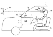
- FIG. 2 is a schematic diagram illustrating a mounting state of a HUD device in a vehicle according to an embodiment as viewed from the left of the vehicle to the right of the vehicle;
- FIG. 2 is a schematic diagram illustrating a mounting state of a HUD device in a vehicle according to an embodiment as viewed from the left of the vehicle to the right of the vehicle;
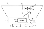
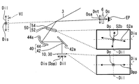
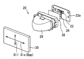
- FIG. 2 is a schematic diagram showing a mounting state of the HUD device in a vehicle according to an embodiment as viewed from the rear of the vehicle to the front of the vehicle; It is a block diagram which shows schematic structure of the HUD apparatus in one Embodiment, It is a perspective view showing a configuration of a projector in an embodiment,
- the HUD device in one embodiment it is a schematic diagram for explaining a relation such as an azimuth angle, It is a graph showing a simulation result of the naked eye brightness when the incident angle to the windshield is 65 degrees, It is a graph showing a simulation result of sunglasses luminance when the incident angle to the windshield is 65 degrees, It is a graph which shows the simulation result of the naked eye brightness
- the HUD device 100 As shown in FIGS. 1 and 2, the HUD device 100 according to an embodiment of the present disclosure is mounted on a vehicle 1 and is accommodated in an accommodation space 1 a in the instrument panel.
- the HUD device 100 projects an image on a windshield 3 as a projection member of the vehicle 1.
- the HUD device 100 displays a virtual image so that the image can be visually recognized by the passenger of the vehicle 1. That is, the light of the image reflected by the windshield 3 reaches the eye point EP of the occupant in the vehicle 1 and the occupant perceives the light of the image as a virtual image VI.
- a crew member can recognize various information by virtual image VI. Examples of various types of information displayed as virtual images include vehicle state values such as vehicle speed and fuel remaining amount, or navigation information such as road information and visibility assistance information.
- the windshield 3 of the vehicle 1 is located above the instrument panel 2 and is formed in a translucent plate shape with glass or synthetic resin. Further, the windshield 3 is disposed so as to be inclined toward the rear of the vehicle toward the upper side of the vehicle. In the windshield 3, a room-side surface forms a smooth projection surface 3 a on which an image is projected in a concave or flat plane shape.
- an occupant sitting on the driver's seat 4a and facing the front of the vehicle 4a and 4b of the vehicle 1 visually recognizes the foreground including the road and the road sign through the windshield 3 and visually displays the virtual image display. be able to.
- the accommodation space 1a in the instrument panel 2 is shifted from the seat of the vehicle 1 in the left-right direction of the vehicle.
- an accommodation space 1 a is provided at the center of the instrument panel 2.
- the virtual image VI is formed at a position shifted in the vehicle left-right direction with respect to the accommodation space 1a.
- the downward direction of the vehicle indicates a direction in which gravity is generated when the vehicle 1 travels on a flat ground or stops on a flat ground.
- the upper side of the vehicle indicates the opposite direction of the lower side of the vehicle.
- the front of the vehicle indicates a direction in which an occupant seated on the seat 4a faces the front.
- the vehicle rear indicates the opposite direction of the vehicle front.
- the left side of the vehicle indicates a left direction as viewed from a passenger facing the front of the vehicle.
- the right side of the vehicle indicates a right direction as viewed from a passenger facing the front of the vehicle.
- the vehicle vertical direction indicates the vehicle upper side and the vehicle lower side.
- the left-right direction of the vehicle indicates the left side of the vehicle and the right side of the vehicle.
- a direction along the vehicle vertical direction is defined as an image vertical direction Dil
- a direction perpendicular to the image vertical direction Dil in the image is defined as an image horizontal direction Dis.
- the direction recognized by the occupant seated on the seat 4a as the vertical direction is the image vertical direction Dil
- the direction recognized as the horizontal direction is the image horizontal direction Dis.
- the HUD device 100 includes a housing 10, a projector 20, a light guide unit 40, and a polarizing plate 50.
- the housing 10 is formed in a dark hollow shape with synthetic resin, for example, corresponding to the accommodation space 1a of the vehicle 1.
- the housing 10 accommodates and fixes the projector 20 and the light guide unit 40.
- the housing 10 has an opening 12.
- the opening 12 is opened at a location facing the windshield 3 in the housing 10, but is eventually blocked by the polarizing plate 50 as will be described later.
- the projector 20 includes a light source 22, a condenser lens 24, a diffuser plate 26, a projection lens 28, and a liquid crystal panel 30, for example, in a box-shaped hollow projector case. Is formed.
- the light source 22 is, for example, a plurality of light emitting diode elements, and is disposed on the light source circuit board 22a.
- the light source 22 is electrically connected to a power source through a wiring pattern on the light source circuit board 22a.
- the light source 22 emits light toward the condenser lens 24 with a light emission amount corresponding to the amount of current when energized. More specifically, the light source 22 emits pseudo white light, for example, by covering a blue light emitting diode with a phosphor.
- the condenser lens 24 is a translucent convex lens made of synthetic resin or glass, and is disposed between the light source 22 and the diffusion plate 26.
- the condenser lens 24 condenses the light source light from the light source 22 and emits it toward the diffusion plate 26.
- the diffusion plate 26 is a plate made of synthetic resin or glass, and is disposed between the condenser lens 24 and the projection lens 28.
- the diffusion plate 26 adjusts the luminance uniformity by diffusing the light from the condenser lens 24 toward the projection lens 28.
- the projection lens 28 is a translucent convex lens made of synthetic resin or glass, and is disposed between the diffusion plate 26 and the liquid crystal panel 30.
- the projection lens 28 condenses the light from the diffusion plate 26 and projects it toward the liquid crystal panel 30.
- the liquid crystal panel 30 is a liquid crystal panel 30 using, for example, a thin film transistor (TFT), and is formed of a plurality of liquid crystal pixels arranged in a two-dimensional direction of an image vertical direction Dil and an image horizontal direction Dis. It is a matrix type liquid crystal panel.
- TFT thin film transistor
- a pair of polarizing plates for liquid crystal and a liquid crystal layer sandwiched between the pair of polarizing plates for liquid crystal are stacked.
- the polarizing plate for liquid crystal has a property that an electric field vector transmits polarized light in a predetermined direction and an electric field vector shields polarized light in a direction substantially perpendicular to the predetermined direction.
- the pair of liquid crystal polarizing plates are arranged so that the predetermined directions are substantially orthogonal to each other.
- the liquid crystal layer can rotate the polarization direction of light incident on the liquid crystal layer in accordance with the applied voltage by applying a voltage for each liquid crystal pixel.
- the projector 20 can project image light.
- the light of the image projected from the projector 20 is polarized according to the arrangement of the polarizing plate for liquid crystal on the exit side.
- the polarization direction Dpp of the light of the image projected from the projector 20 is along the image horizontal direction Dis.
- the screen of the liquid crystal panel 30 has the image horizontal direction Dis having a longer dimension than the image vertical direction Dil, and therefore the image horizontal direction Dis corresponds to the longitudinal direction in the image.
- the vertical direction Dil corresponds to the short direction.
- the light guide 40 is an optical system that guides the image light from the projector 20 toward the windshield 3.
- the light guide unit 40 includes a plane mirror 42 and a concave mirror 44.
- the flat mirror 42 is formed by evaporating aluminum as a reflective surface 42a on the surface of a base material made of synthetic resin or glass.
- the reflection surface 42a is provided on the side of the projector 20 facing the liquid crystal panel 30 and the concave mirror 44, and is formed in a flat planar shape.
- the plane mirror 42 reflects the image light from the liquid crystal panel 30 toward the concave mirror 44.
- the concave mirror 44 is formed by evaporating aluminum as the reflecting surface 44a on the surface of a base material made of synthetic resin or glass.
- the reflecting surface 44a is provided on the side facing the flat mirror 42 and the windshield 3, and is formed in a smooth curved surface as a concave surface in which the center of the concave mirror 44 is recessed.
- the concave mirror 44 reflects the image light from the plane mirror 42 toward the windshield 3.
- the light of the image from the projector 20 forms an optical path through the light guide 40 and the windshield 3 as shown in FIG.
- the polarizing plate 50 is disposed on the optical path between the light guide 40 and the windshield 3.
- the polarizing plate 50 is provided by covering the entire surface of the opening 12 of the housing 10.
- the polarizing plate 50 includes a polarizing element layer 52 and an infrared light regulating layer 54, which are stacked on each other.
- the polarizing element layer 52 is formed by adding iodine to polyvinyl alcohol, for example, and has a transmission axis 52a and a light shielding axis 52b substantially orthogonal to each other depending on the orientation direction of iodine molecules.
- the transmission axis 52a is an axis that maximizes the transmittance of the corresponding polarized light.
- the polarized light corresponding to the transmission axis 52a is polarized light having an electric field vector along the transmission axis 52a.
- the light shielding axis 52b is an axis that minimizes the transmittance of the corresponding polarized light.
- the polarized light corresponding to the light shielding axis 52b is polarized light having an electric field vector along the light shielding axis 52b.
- the light shielding axis 52b of the polarizing element layer 52 having such a configuration is an absorption axis for absorbing light. That is, when the polarized light corresponding to the light shielding axis 52b as the absorption axis is incident on the polarizing element layer 52, the absorption rate is maximized.
- the infrared light regulating layer 54 is disposed, for example, closer to the windshield 3 than the polarizing element layer 52.
- the infrared light regulating layer 54 is formed by laminating two or more kinds of dielectric films having different refractive indexes. Each film thickness in each dielectric film is set as appropriate by, for example, calculating the interference of light with a computer in order to obtain spectral characteristics such that at least some of infrared light has higher reflectance than visible light. Is done.
- part of infrared light incident on the infrared light regulating layer 54 is absorbed.
- the infrared light regulating layer 54 regulates the transmission of infrared light out of the external light that enters the device 100 from the outside of the device 100 while transmitting the image light that is visible light.
- the external light for example, sunlight that passes through the windshield 3 and enters the apparatus 100 can be cited.
- the polarizing plate 50 that transmits part of the image light from the light guide 40 through the opening 12 toward the windshield 3 outside the housing 10 will be described in detail below.
- the directions of the transmission axis 52a and the light shielding axis 52b are set as follows.
- the general polarized sunglasses 6 has a transmission axis Dst (hereinafter referred to as sunglasses transmission axis) set in the vertical direction and an absorption axis Dsa (hereinafter referred to as sunglasses absorption axis) set in the horizontal direction.
- sunglasses transmission axis a transmission axis set in the vertical direction
- sunglasses absorption axis an absorption axis set in the horizontal direction.
- the polarized sunglasses 6 has a maximum transmittance for light polarized in the vertical direction of the vehicle 1. Is the minimum transmittance for light polarized in the vertical direction. Due to the transmission characteristics of the polarized sunglasses 6, the luminance of the visible virtual image VI (hereinafter, sunglasses luminance I p ) changes according to the setting of the direction of the transmission axis 52 a and the light shielding axis 52 b.
- the transmission axis 52a and the light shielding axis 52b of the polarizing plate 50 are used. It seems that a certain luminance can be obtained without depending on the arrangement of the.
- the reflectance of the image light at the windshield 3 depends on the polarization direction of the image light incident on the windshield 3.
- the luminance of the visually recognized virtual image VI (hereinafter referred to as naked eye luminance I) changes in accordance with the setting of the direction of the transmission axis 52a and the light shielding axis 52b.
- the naked eye luminance I is represented by the number 1
- sunglasses luminance I p is represented by the number 2.
- I 0 is the brightness of the image light when the windshield 3 is incident.
- ⁇ is an angle formed by the sunglasses absorption axis Dsa and the polarization direction of the light of the image after being reflected by the windshield 3.
- ⁇ is an angle formed by the sunglasses transmission axis Dst and the tangential direction Drt of the reflection cross section of the image light reflected by the windshield 3.
- the reflection cross section is a plane including a light ray incident on and reflected by the windshield 3 and a normal line of the windshield 3 at the incident and reflection positions, and is generally called an incident surface.
- R s is the s-polarized reflectance of the windshield 3.
- R p is the p-polarized reflectance of the windshield 3.
- T is a transmittance for polarized light along the sunglasses transmission axis Dst of the polarized sunglasses 6.
- the ratio I p / I between the naked eye luminance I and the sunglasses luminance I p is expressed by the following expression 3.
- the variables for controlling the naked eye luminance I, the sunglasses luminance I p , and the ratio I p / I are ⁇ and ⁇ .
- the positional relationship between the accommodation space 1a, the windshield 3 and the driver's seat 4a must be changed, and the functionality and design of the vehicle 1 and the arrangement of other devices in the vehicle 1 Therefore, it is extremely difficult to change the positional relationship.
- the naked eye luminance I is expressed by the formula 4
- the sunglasses luminance I p is expressed by the formula 5.
- ⁇ 0 is an angle formed by the sunglasses absorption axis Dsa and the polarization direction of the light of the image incident on the polarizing plate 50.
- ⁇ is an angle formed by the sunglasses absorption axis Dsa and the transmission axis 52 a of the polarizing plate 50.
- Equations 4 to 6 it is understood that the naked eye luminance I, the sunglasses luminance I p , and the ratio I p / I can be controlled by appropriately setting ⁇ .
- the sunglasses transmission axis Dst coincides with the image vertical direction Dil
- the sunglasses absorption axis Dsa coincides with the image horizontal direction Dis, so that these can be replaced.
- the s-polarized reflectance R s is larger than the p-polarized reflectance R p .
- each azimuth angle is defined with the image horizontal direction Dis as a reference azimuth.
- the azimuth angle of the polarization direction Dpp light image projected from the projector 20 is defined as a projection polarization azimuth angle alpha 0.
- the azimuth angle of the transmission axis 52a of the polarizing plate 50 is defined as the transmission axis azimuth angle ⁇ .
- the azimuth angle with the image vertical direction Dil as the reference azimuth and the azimuth angle in the tangential direction Drt of the reflection cross section is defined as the reflection cross section azimuth angle ⁇ .
- the polarization direction of the light of the image incident on the polarizing plate 50 is, for example, about ⁇ 3 degrees with respect to the polarization direction Dpp of the projector 20 (light guide Depending on the configuration of 40, there may be a deviation of about ⁇ 10 degrees).
- the polarization direction Dpp and the polarization direction of the light of the image incident on the polarizing plate 50 Can be considered the same.
- a projection polarization azimuth angle alpha 0 is 0 alpha in Equation 4-5
- the reflection section azimuth ⁇ is C 4-6 ⁇ can be regarded as a corresponding physical quantity.
- ⁇ 0 is the projection polarization azimuth
- ⁇ is the transmission axis azimuth
- ⁇ is the reflection cross-section azimuth.
- the projection polarization azimuth angle ⁇ 0 is 0 degree.
- Simulation A shows the naked eye luminance I and the sunglasses luminance Ip when the incident angle of the light of the image incident on the windshield 3 is 65 degrees.
- Simulation B shows the naked eye luminance I and the sunglasses luminance Ip when the incident angle of the light of the image incident on the windshield 3 is 60 degrees.
- the angle of incidence of the simulation B since it is characterized in that the Brewster angle near, p-polarized light reflectivity R p for the s-polarized light reflectivity R s is in the smaller condition.
- RHD means a right-hand drive vehicle
- LHD means a left-hand drive vehicle. That is, in one right-hand drive vehicle, the HUD device 100 housed in the housing space 1a at the center of the instrument panel 2 is passed through the windshield 3 to passengers seated in the driver's seat 4a that is the seat on the right side of the vehicle.
- the virtual image VI is visually recognized. That is, the virtual image VI is formed at a position shifted to the right of the vehicle from the accommodation space 1a.
- the HUD device 100 housed in the housing space 1a at the center of the instrument panel 2 is passed through the windshield 3 to the occupant seated in the driver's seat 4a, which is a seat on the left side of the vehicle.
- Make VI visible That is, the virtual image VI is formed at a position shifted to the left of the vehicle from the accommodation space 1a.
- the reflection section azimuth angle ⁇ is set to be positive in the case of a right-hand drive vehicle, in other words, when the reflection section tilts to the right of the vehicle as it goes upward. That is, in the case of a left-hand drive vehicle, in other words, the reflection cross-section azimuth angle ⁇ is set to be negative when the reflection cross-section tilts to the left of the vehicle as it goes upward.
- the transmission axis azimuth angle ⁇ is set so that the clockwise direction from the reference azimuth is positive and the counterclockwise direction from the reference azimuth is negative in the viewpoint of FIG.
- the sunglasses luminance Ip shown in FIG. 7 includes a right-hand drive vehicle and a region where the transmission axis azimuth ⁇ is negative (that is, a region on the upper right in FIG. 7), and a left-hand drive vehicle and a region where the transmission axis azimuth ⁇ is positive. (That is, the lower left area in FIG. 7) tends to increase.
- the transmission axis azimuth ⁇ is set to be negative in the case of a right-hand drive vehicle, and in the case of a left-hand drive vehicle.
- the transmission axis azimuth ⁇ is preferably set to be positive.
- the sunglasses luminance Ip shown in FIG. 9 includes a right-hand drive vehicle and a region where the transmission axis azimuth ⁇ is negative (that is, a region on the upper right in FIG. 9), and a left-hand drive vehicle and a region where the transmission axis azimuth ⁇ is positive. (That is, the lower left area in FIG. 9) tends to increase.
- the transmission axis azimuth ⁇ is set to be negative
- the transmission axis azimuth ⁇ is set to be positive.
- the polarizing plate 50 has the following arrangement. As shown in FIGS. 3 and 5, the polarizing plate 50 is arranged with the projection polarization azimuth angle ⁇ 0 and the transmission axis azimuth angle ⁇ being different. Thereby, the polarization direction of the light of the image reflected by the windshield 3 is adjusted so as to be inclined with respect to both the image vertical direction Dil and the image horizontal direction Dis. Note that the polarization direction includes the major axis direction of elliptically polarized light.
- the first direction D1 and second direction D2 are compared with the traveling direction Dc of the image light as the rotation axis.
- the first direction D1 is a direction in which the tangential direction Drt of the reflection cross section of the image light reflected by the windshield 3 is turned to less than 90 degrees with respect to the image vertical direction Dil.
- the second direction D2, to the direction indicated by the projected polarization azimuth angle alpha 0, the direction indicated by the transmission axis azimuth ⁇ is orientation are turning to less than 90 degrees.
- the polarizing plate 50 is disposed so that the first direction D1 and the second direction D2 are opposite to each other. For example, in the case of the right-hand drive vehicle shown in FIGS. 2 and 5, the first direction D1 is counterclockwise and the second direction D2 is clockwise. In the case of a left-hand drive vehicle, the first direction D1 is clockwise and the second direction D2 is counterclockwise.
- a polarizing plate 50 are arranged.
- the polarizing plate 50 is disposed on the optical path between the light guide 40 and the windshield 3 as the projection member. Then, arranging the transmission axis azimuth beta, and a projection polarization azimuth angle alpha 0, the transmission axis 52a of the polarizer 50 so as to vary. By doing so, the polarization state of the image light that is projected from the projector 20 and then guided to the light guide 40 and heads toward the windshield 3 due to, for example, mounting space is an ideal state. Even if not, adjustment can be performed by the polarizing plate 50. Here, the adjustment is performed so that the polarization direction of the light of the image reflected by the windshield 3 is inclined with respect to both the image vertical direction Dil and the image horizontal direction Dis.
- the first direction D1 in which the tangential direction Drt of the light reflection cross section of the image reflected by the windshield 3 is less than 90 degrees with respect to the image vertical direction Dil, and the projection polarization direction to the direction indicated by the angle alpha 0, the direction indicated by the transmission axis azimuth ⁇ is the second direction D2 that are turning to less than 90 degrees, are opposite rotation directions from one another.
- the polarization direction Dpp of the light of the image projected from the projector 20 is along the image horizontal direction Dis. While ensuring the amount of s-polarized light in the reflection cross section of the windshield 3 by the polarization direction Dpp of the projector 20 as described above, while keeping the arrangement of the transmission axis 52a of the polarizing plate 50 finely adjusted with respect to the polarization direction Dpp, The brightness can be balanced between the case where the occupant visually recognizes the virtual image VI with the naked eye and the case where the occupant visually recognizes the virtual image VI while wearing the polarized sunglasses.
- a projection polarization azimuth angle alpha the absolute value of the difference between the transmission axis azimuth beta, is less than 45 degrees.
- the polarizing plate 50 covers the entire surface of the opening 12.
- the polarizing plate 50 allows the image light to pass from the light guide 40 to the windshield 3 while preventing the internal structure of the HUD device 100 from being seen from the outside, so that the visibility in the naked eye state can be achieved. And the visibility in a state where the polarized sunglasses 6 are worn can be made compatible.
- the polarizing plate 50 has the infrared light regulating layer 54 that absorbs infrared light. If it does in this way, it can suppress that the infrared light from the apparatus 100 exterior reaches
- the incident angle of the light of the image incident on the windshield 3 may be set to other than 60 degrees and 65 degrees.
- the incident angle may be set in the range of 20 to 80 degrees.
- the polarization direction Dpp of the light of the image projected from the projector 20 may not be along the image horizontal direction Dis.
- the projection polarization azimuth angle ⁇ 0 may be set in a range of ⁇ 45 to +45 degrees, and a projector 45 of +45 degrees or ⁇ 45 degrees using a general liquid crystal panel may be employed.
- the polarizing plate 50 may not cover the entire surface of the opening 12.
- the polarizing plate 50 may not have the infrared light regulating layer 54.
- a method of projecting image light using, for example, a linearly polarized laser is adopted in addition to the method using the liquid crystal panel 30. May be.
- the light guide unit 40 may be configured only by the concave mirror 44, or may be configured by adding other optical elements.
- the present disclosure can be applied to a part of an image.
- the head-up display device is mounted on the vehicle 1, projects an image on the projection member 3, and the image light is reflected by the projection member, thereby displaying the image in a virtual image so that the occupant can visually recognize the image.
- the head-up display device includes a projector 20, a light guide unit 40, and a polarizing plate 50.
- the projector 20 projects polarized image light.
- the light guide 40 guides the image light from the projector toward the projection member.
- the polarizing plate 50 is disposed on the optical path between the light guide unit and the projection member, and has a transmission axis 52a that maximizes the transmittance of the corresponding polarized light.
- a direction along the vertical direction of the vehicle is defined as an image vertical direction Dil
- a direction perpendicular to the image vertical direction in the image is defined as an image horizontal direction Dis.
- the azimuth angle with the horizontal direction of the image as the reference azimuth, the projected polarization azimuth angle ⁇ 0 that is the azimuth angle of the polarization direction Dpp of the image light projected from the projector 20, and the azimuth angle of the transmission axis of the polarizing plate A certain transmission axis azimuth ⁇ is further defined.
- the polarizing plate 50 makes the polarization direction of the image light reflected by the projection member different from both the image vertical direction Dil and the image horizontal direction Dis by making the projection polarization azimuth angle ⁇ 0 and the transmission axis azimuth angle ⁇ different. Adjust so that it tilts.
- the polarizing plate is disposed on the optical path between the light guide unit and the projection member. Then, the transmission axis of the polarizing plate is arranged so that the transmission axis azimuth is different from the projection direction azimuth. By doing so, the polarization state of the light of the image directed to the projection member after being projected from the projector due to, for example, the mounting space was not ideal.
- adjustment can be performed by a polarizing plate.
- the adjustment is performed so that the polarization direction of the light of the image reflected by the projection member is inclined with respect to both the image vertical direction and the image horizontal direction.
Landscapes
- Physics & Mathematics (AREA)
- General Physics & Mathematics (AREA)
- Optics & Photonics (AREA)
- Engineering & Computer Science (AREA)
- Transportation (AREA)
- Combustion & Propulsion (AREA)
- Chemical & Material Sciences (AREA)
- Mechanical Engineering (AREA)
- Health & Medical Sciences (AREA)
- Toxicology (AREA)
- Instrument Panels (AREA)
- Liquid Crystal (AREA)
- Fittings On The Vehicle Exterior For Carrying Loads, And Devices For Holding Or Mounting Articles (AREA)
Abstract
投射器(20)は、偏光した画像の光を投射する。導光部(40)は、投射器(20)からの画像の光を投影部材へ向けて導光する。偏光板(50)は、導光部(40)と投影部材との間の光路上に配置され、対応する偏光の透過率が最大となる透過軸(52a)を有する。画像が虚像表示されるときに、車両の上下方向に沿う方向は画像縦方向(Dil)であり、画像において画像縦方向と垂直な方向は画像横方向(Dis)である。画像横方向を基準方位として、投射器から投射される画像の光の偏光方向(Dpp)の方位角は投射偏光方位角(α0)であり、偏光板の透過軸の方位角は透過軸方位角(β)である。偏光板(50)は、投射偏光方位角(α0)と透過軸方位角(β)とを異ならせることにより、投影部材に反射された画像の光の偏光方向が画像縦方向(Dil)及び画像横方向(Dis)の両方に対して傾くように調整する。
Description
本出願は、2015年12月3日に出願された日本出願番号2015-236912号に基づくもので、ここにその記載内容を援用する。
本開示は、車両に搭載され、画像を乗員により視認可能に虚像表示するヘッドアップディスプレイ装置(以下、HUD装置を略称とする)に関する。
従来、車両に搭載され、画像を乗員により視認可能に虚像表示するHUD装置が知られている。特許文献1に開示のHUD装置は、偏光した画像の光を投射する投射器と、投射器からの画像の光を投影部材へ向けて導光する導光部と、導光部と投影部材との間の光路上に配置される偏光板と、を備えている。
ここで、偏光板は、投射器からの迷光を遮光するように、配置されている。
さて、虚像を視認する乗員は、裸眼の状態で虚像を視認する場合もあれば、偏光サングラスを装用した状態で虚像を視認する場合もある。ここで、偏光サングラスは、一般的に、車両の上下方向に偏光する光に対して最大透過率となるように、設定されている。
この点、特許文献1のように迷光の遮光のために、偏光板を配置すると、偏光板を透過して投影部材に反射された画像の光において、車両の上下方向の偏光の成分が十分に得られないことが懸念される。車両の上下方向の偏光の成分が十分に得られないと、偏光サングラスを装用した状態で輝度が足りずに、虚像の視認が困難になってしまう。
本開示は、裸眼状態での視認性と、偏光サングラスを装用した状態での視認性とを両立するHUD装置を提供することを目的とする。
本開示の第一の態様において、ヘッドアップディスプレイ装置は、車両に搭載され、投影部材に画像を投影し、前記画像の光が前記投影部材に反射されることで前記画像を乗員により視認可能に虚像表示する。ヘッドアップディスプレイ装置は、偏光した前記画像の光を投射する投射器を備える。ヘッドアップディスプレイ装置は、前記投射器からの前記画像の光を前記投影部材へ向けて導光する導光部を更に備える。ヘッドアップディスプレイ装置は、前記導光部と前記投影部材との間の光路上に配置され、対応する偏光の透過率が最大となる透過軸を有する偏光板を更に備える。前記画像が虚像表示されるときに、前記車両の上下方向に沿う方向を画像縦方向と、前記画像において前記画像縦方向と垂直な方向を画像横方向と、を定義する。前記画像横方向を基準方位とした方位角であって、前記投射器から投射される前記画像の光の偏光方向の方位角である投射偏光方位角と、前記偏光板の透過軸の方位角である透過軸方位角と、をさらに定義する。前記偏光板は、前記投射偏光方位角と前記透過軸方位角とを異ならせることにより、前記投影部材に反射された前記画像の光の偏光方向が前記画像縦方向及び前記画像横方向の両方に対して傾くように調整する。
本開示についての上記目的およびその他の目的、特徴や利点は、添付の図面を参照しながら下記の詳細な記述により、より明確になる。その図面は、
一実施形態におけるHUD装置の車両への搭載状態を示す模式図であって、車両左方から車両右方に見た図であり、
一実施形態におけるHUD装置の車両への搭載状態を示す模式図であって、車両後方から車両前方に見た図であり、
一実施形態におけるHUD装置の概略的構成を示す構成図であり、
一実施形態における投射器の構成を示す斜視図であり、
一実施形態におけるHUD装置において、方位角等の関係を説明するための模式図であり、
ウインドシールドへの入射角65度の場合の裸眼輝度のシミュレーション結果を示すグラフであり、
ウインドシールドへの入射角65度の場合のサングラス輝度のシミュレーション結果を示すグラフであり、
ウインドシールドへの入射角60度の場合の裸眼輝度のシミュレーション結果を示すグラフであり、また
ウインドシールドへの入射角60度の場合のサングラス輝度のシミュレーション結果を示すグラフである。
以下、本開示の一実施形態を図面に基づいて説明する。
図1,2に示すように、本開示の一実施形態によるHUD装置100は、車両1に搭載され、インストルメントパネル内の収容スペース1aに収容されている。HUD装置100は、車両1の投影部材としてのウインドシールド3に画像を投影する。画像の光がウインドシールド3に反射されることで、HUD装置100は、画像を車両1の乗員により視認可能に虚像表示する。すなわち、ウインドシールド3に反射される画像の光が、車両1の室内において乗員のアイポイントEPに到達し、当該乗員が当該画像の光を虚像VIとして知覚する。そして、乗員は、虚像VIにより各種情報を認識することができる。画像として虚像表示される各種情報としては、例えば、車速、燃料残量等の車両状態値、又は、道路情報、視界補助情報等のナビゲーション情報が挙げられる。
車両1のウインドシールド3は、インストルメントパネル2よりも車両上方に位置し、ガラスないしは合成樹脂等により透光性の板状に形成されている。また、ウインドシールド3は、車両上方に向かう程車両後方に傾斜して配置されている。ウインドシールド3において室内側の面は、画像が投影される滑らかな投影面3aを凹面状又は平坦な平面状に形成している。こうして、車両1の座席4a,4bのうち運転席4aに着座して車両前方を向く乗員は、当該ウインドシールド3を通して道路及び道路標識等を含む前景を視認すると共に、画像の虚像表示を視認することができる。
また、本実施形態において、インストルメントパネル2内の収容スペース1aは、車両1の座席とは車両左右方向にずれた位置となっている。特に本実施形態では、インストルメントパネル2の中央部に、収容スペース1aが設けられている。こうして、収容スペース1aに対して、車両左右方向にずれた位置に虚像VIが結像される。
ここで本実施形態において、車両下方とは、車両1が平地を走行するとき又は平地に停止するときに重力が生ずる方向を示す。車両上方とは、車両下方の反対方向を示す。車両前方とは、座席4aに着座した乗員が正面を向く方向を示す。車両後方とは、車両前方の反対方向を示す。車両左方とは、車両前方を向く乗員からみた左の方向を示す。車両右方とは、車両前方を向く乗員から見た右の方向を示す。さらに、車両上下方向とは、車両上方及び車両下方を示すものとする。車両左右方向とは、車両左方及び車両右方を示すものとする。
また、画像が虚像表示されるときに車両上下方向に沿う方向を、画像縦方向Dilと定義し、当該画像において画像縦方向Dilと垂直な方向を、画像横方向Disと定義する。言い換えると、画像において、座席4aに着座した乗員が縦の方向と認識する方向が画像縦方向Dilであり、横の方向と認識する方向が画像横方向Disである。
このようなHUD装置100の具体的構成を、図1~5に基づいて、以下に説明する。HUD装置100は、図3に示すように、ハウジング10、投射器20、導光部40、及び偏光板50を備えている。
ハウジング10は、車両1の収容スペース1aに対応して、例えば合成樹脂により暗色の中空状に形成されている。ハウジング10は、投射器20及び導光部40を収容及び固定している。また、ハウジング10は、開口部12を有している。開口部12は、ハウジング10のうちウインドシールド3と対向する箇所において開口しているが、後述するように、結局は偏光板50によって塞がれている。
投射器20は、図4にも詳細を示すように、光源22、集光レンズ24、拡散板26、投射レンズ28、及び液晶パネル30を有し、例えば箱型中空状の投射器ケースにこれらを収容して形成されている。
光源22は、例えば複数の発光ダイオード素子であり、光源用回路基板22a上に配置されている。光源22は、光源用回路基板22a上の配線パターンを通じて、電源と電気的に接続されている。光源22は、通電により電流量に応じた発光量にて光を集光レンズ24へ向けて発する。より詳細には、光源22は、例えば青色発光ダイオードを蛍光体で覆うことにより、疑似白色での発光が実現されている。
集光レンズ24は、合成樹脂ないしはガラス等からなる透光性の凸レンズであり、光源22と拡散板26との間に配置されている。集光レンズ24は、光源22からの光源光を集光して拡散板26へ向けて射出する。
拡散板26は、合成樹脂ないしはガラス等により形成された板であり、集光レンズ24と投射レンズ28との間に配置されている。拡散板26は、集光レンズ24からの光を投射レンズ28へ向けて拡散することで、輝度の均一性を調整する。
投射レンズ28は、合成樹脂ないしはガラス等からなる透光性の凸レンズであり、拡散板26と液晶パネル30との間に配置されている。投射レンズ28は、拡散板26からの光を集光して液晶パネル30へ向けて投射する。
液晶パネル30は、例えば薄膜トランジスタ(Thin film Transistor、TFT)を用いた液晶パネル30であって、画像縦方向Dil及び画像横方向Disの2次元方向に配列された複数の液晶画素から形成されるアクティブマトリクス型の液晶パネルである。液晶パネル30では、一対の液晶用偏光板及び当該一対の液晶用偏光板に挟まれた液晶層等が積層されている。液晶用偏光板は、電場ベクトルが所定方向の偏光を透過させ、電場ベクトルが所定方向と実質垂直な方向の偏光を遮光する性質を有している。一対の液晶用偏光板は、当該所定方向を互いに実質直交して配置されている。液晶層は、液晶画素毎の電圧印加により、印加電圧に応じて液晶層に入射する光の偏光方向を回転させることが可能となっている。
したがって、液晶パネル30が液晶画素毎の透過率を制御することで、投射器20は、画像の光を投射することが可能となっている。ここで、投射器20から投射される画像の光は、射出側の液晶用偏光板の配置に応じて、偏光したものとなっている。具体的に本実施形態では、投射器20から投射される画像の光の偏光方向Dppは、画像横方向Disに沿っている。
なお、本実施形態において液晶パネル30の画面は、画像横方向Disの寸法が画像縦方向Dilの寸法よりも長くなっているため、画像において画像横方向Disが長手方向に対応しており、画像縦方向Dilが短手方向に対応している。
導光部40は、投射器20からの画像の光を、ウインドシールド3へ向けて導光する光学系である。導光部40は、平面鏡42及び凹面鏡44を有している。
平面鏡42は、合成樹脂ないしはガラス等からなる基材の表面に、反射面42aとしてアルミニウムを蒸着させること等により形成されている。反射面42aは、投射器20の液晶パネル30及び凹面鏡44と向かい合う側に設けられ、平坦な平面状に形成されている。そして、平面鏡42は、液晶パネル30からの画像の光を、凹面鏡44へ向けて反射する。
凹面鏡44は、合成樹脂ないしはガラス等からなる基材の表面に、反射面44aとしてアルミニウムを蒸着させること等により形成されている。反射面44aは、平面鏡42及びウインドシールド3と向かい合う側に設けられ、凹面鏡44の中心が凹む凹面として、滑らかな曲面状に形成されている。そして、凹面鏡44は、平面鏡42からの画像の光を、ウインドシールド3へ向けて反射する。
こうして、投射器20からの画像の光により、図3に示すように、導光部40及びウインドシールド3を介した光路が構成されている。
偏光板50は、導光部40とウインドシールド3との間の光路上に配置されている。特に本実施形態では、偏光板50は、ハウジング10の開口部12の全面を塞いて設けられている。偏光板50は、偏光素子層52及び赤外光規制層54を有しており、これらは互いに積層されている。
偏光素子層52は、例えばポリビニルアルコールにヨウ素を添加して形成され、ヨウ素分子の配向方向によって透過軸52aと遮光軸52bとを互いに実質直交した状態で有している。透過軸52aは、対応する偏光の透過率が最大となる軸である。ここで透過軸52aに対応する偏光とは、電場ベクトルが当該透過軸52aに沿った偏光である。遮光軸52bは、対応する偏光の透過率が最小となる軸である。ここで遮光軸52bに対応する偏光とは、電場ベクトルが当該遮光軸52bに沿った偏光である。このような構成の偏光素子層52の遮光軸52bは、光を吸収する吸収軸となっている。すなわち、吸収軸としての遮光軸52bに対応する偏光が偏光素子層52に入射した場合、吸収率が最大となる。
赤外光規制層54は、例えば偏光素子層52よりもウインドシールド3側に配置されている。赤外光規制層54は、例えば互いに屈折率が異なる2種類以上の誘電体膜を積層して形成されている。各誘電体膜における各膜厚は、可視光に対して赤外光うち少なくとも一部の反射率が高くなるような分光特性を得るために、例えばコンピュータにより光の干渉を計算することによって適宜設定される。また、誘電体膜に赤外光の一部を吸収する素材を用いることにより、赤外光規制層54に入射する赤外光の一部が吸収されるようになっている。こうして、赤外光規制層54は、可視光である画像の光を透過させつつ、装置100外から装置100内へ入射しようとする外光のうち赤外光の透過を規制するようになっている。外光としては、例えばウインドシールド3を透過して装置100内へ入射しようとする太陽光が挙げられる。
こうした、導光部40から開口部12を通じて画像の光の一部をハウジング10外のウインドシールド3に向けて透過させる偏光板50の配置について、以下に詳細に説明する。具体的には、虚像VIの輝度を考慮して、偏光板50において、透過軸52a及び遮光軸52bの方向が以下のように設定される。
乗員が偏光サングラス6を装用した状態で虚像VIを視認する場合、ウインドシールド3に反射された後の画像の光の偏光方向の影響を受けて、虚像VIの輝度が変化する。具体的に、一般的な偏光サングラス6は、透過軸Dst(以下、サングラス透過軸)が鉛直方向に設定され、吸収軸Dsa(以下、サングラス吸収軸)が水平方向に設定されている。このため、乗員が偏光サングラス6を装用した状態で車両1の座席に着座すると、当該偏光サングラス6は、車両1の上下方向に偏光する光に対して最大透過率となり、車両1の偏光方向とは垂直な方向に偏光する光に対して最小透過率となる。このような偏光サングラス6の透過特性に起因して、視認される虚像VIの輝度(以下、サングラス輝度Ip)は、透過軸52a及び遮光軸52bの方向の設定に応じて変化する。
他方、乗員が裸眼の状態で虚像VIを視認する場合、ウインドシールド3に反射された後の画像の光は偏光方向の影響を受けないため、一見すると偏光板50の透過軸52a及び遮光軸52bの配置に依存せずに一定の輝度が得られると思われる。しかしながら、フレネルの式に示されるように、ウインドシールド3での画像の光の反射率は、当該ウインドシールド3に入射する画像の光の偏光方向に依存する。このため、視認される虚像VIの輝度(以下、裸眼輝度I)は、透過軸52a及び遮光軸52bの方向の設定に応じて変化する。
ここでまず、比較例として、偏光板50を設けなかった場合を考える。この場合に、裸眼輝度Iは数1で表され、サングラス輝度Ipは数2で表される。
数1,2により、裸眼輝度Iとサングラス輝度Ipとの比率Ip/Iは、以下の数3で表される。

上述の数1~3を、偏光板50が設けられた本実施形態に応用すると、裸眼輝度Iは数4で表され、サングラス輝度Ipは数5で表される。
数4,5により、裸眼輝度Iとサングラス輝度Ipとの比率Ip/Iは、以下の数6で表される。

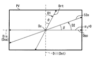
ここで、投射器20から導光部40、偏光板50、及びウインドシールド3を光路に沿って反射又は透過しつつ伝播してゆく画像の光について、その進行方向Dcに垂直な振動面PV上において、画像横方向Disを基準方位として各方位角を定義する。具体的に、投射器20から投射される画像の光の偏光方向Dppの方位角を、投射偏光方位角α0と定義する。偏光板50の透過軸52aの方位角を、透過軸方位角βと定義する。
この他、画像縦方向Dilを基準方位とした方位角であって、反射断面の接線方向Drtの方位角を、反射断面方位角θと定義する。
図5では、本実施形態のHUD装置100において、アイポイントEPからウインドシールド3を視認する乗員の視点で(すなわち、画像の光の進行方向Dcとは逆にウインドシールド3を見た視点で)、これら方位角α0,β,θを重ねあわせて図示がされている。なお、導光部40の反射素子42,44の配置によっては、投射器20の偏光方向Dppに対して、偏光板50に入射する画像の光の偏光方向が例えば±3度程度(導光部40の構成によっては±10度程度)ずれてしまう場合があるが、輝度の比率Ip/I等の傾向を知る上では、偏光方向Dppと偏光板50に入射する画像の光の偏光方向とを同じとみなしても差支えない。また、上述の読替を考慮すると、投射偏光方位角α0は数4~5におけるα0と、透過軸方位角βは数4~6におけるβと、反射断面方位角θは数4~6におけるθと、それぞれ対応する物理量とみなすことができる。
そして以下では、α0を投射偏光方位角として、またβを透過軸方位角として、θを反射断面方位角として、説明を続ける。なお、特に本実施形態では、投射器20から投射される画像の光の偏光方向Dppは、画像横方向Disに沿っているため、投射偏光方位角α0は、0度となっている。
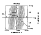
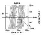
上述の数4~6の知見を得た発明者らのシミュレーションにより、裸眼輝度I及びサングラス輝度Ipと、偏光板50の配置との関係について図6~9のグラフを用いてさらに詳細に説明する。図6~9の各グラフでは、透過軸方位角βを横軸にとり、反射断面方位角θを縦軸にとり、これらパラメータβ,θを変化させた場合において、裸眼輝度I及びサングラス輝度Ipがどのように変化するかが示されている。
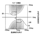
シミュレーションA(図6,7参照)では、ウインドシールド3に入射する画像の光の入射角が65度である場合の裸眼輝度I及びサングラス輝度Ipについて示す。シミュレーションB(図8,9参照)では、ウインドシールド3に入射する画像の光の入射角が60度である場合の裸眼輝度I及びサングラス輝度Ipについて示す。シミュレーションAと比較して、シミュレーションBの入射角は、ブリュースター角近傍という特徴があるため、s偏光反射率Rsに対するp偏光反射率Rpがより小さい条件となっている。
また、図6~9においてRHDとは、右ハンドル車を意味し、LHDとは、左ハンドル車を意味している。すなわち、一方の右ハンドル車では、インストルメントパネル2中央部の収容スペース1aに収容されたHUD装置100は、ウインドシールド3を介して、車両右方の座席である運転席4aに着座する乗員に、虚像VIを視認させる。すなわち、収容スペース1aよりも車両右方にずれた位置に虚像VIが結像される。
他方の左ハンドル車では、インストルメントパネル2中央部の収容スペース1aに収容されたHUD装置100は、ウインドシールド3を介して、車両左方の座席である運転席4aに着座する乗員に、虚像VIを視認させる。すなわち、収容スペース1aよりも車両左方にずれた位置に虚像VIが結像される。
なお、図6~9において反射断面方位角θは、右ハンドル車の場合、換言すると、車両上方に向かうに従って車両右方に反射断面が傾く場合、正となるように設定されている。すなわち反射断面方位角θは、左ハンドル車の場合、換言すると、車両上方に向かうに従って車両左方に反射断面が傾く場合、負となるように設定されている。
また、透過軸方位角βは、図5の視点において基準方位から右回りとなる向きが正となり、基準方位から左回りとなる向きが負となるように設定されている。ここで、図3の偏光板50上の透過軸52aと、図5の視点における透過軸52aとでは、ウインドシールド3における反射により、方向が反転した見え方となるので注意が必要である。
シミュレーションAについて詳細を説明する。図6に示される裸眼輝度Iは、透過軸方位角βが0度近傍である場合に、最も大きくなり、透過軸方位角βが大きくなるに従って、輝度が小さくなっていることがわかる。図7に示されるサングラス輝度Ipは、右ハンドル車かつ透過軸方位角βが負である領域(すなわち図7の右上の領域)、及び左ハンドル車かつ透過軸方位角βが正である領域(すなわち図7の左下の領域)にて、大きくなる傾向がある。
したがって、裸眼輝度I及びサングラス輝度Ipの両方を十分に得るためには、右ハンドル車の場合は、透過軸方位角βが負に設定されることが好適であり、左ハンドル車の場合は、透過軸方位角βが正に設定されることが好適である。特に本実施形態では、右ハンドル車の場合は図6,7の範囲AR、左ハンドル車の場合は図6,7の範囲ALに設定されることが好適である。
シミュレーションBについて詳細を説明する。図8に示される裸眼輝度Iは、透過軸方位角βが0度近傍である場合に、最も大きくなり、透過軸方位角βが大きくなるに従って、輝度が小さくなっていることがわかる。図9に示されるサングラス輝度Ipは、右ハンドル車かつ透過軸方位角βが負である領域(すなわち図9の右上の領域)、及び左ハンドル車かつ透過軸方位角βが正である領域(すなわち図9の左下の領域)にて、大きくなる傾向がある。
したがって、シミュレーションAと同様に、裸眼輝度I及びサングラス輝度Ipの両方を十分に得るためには、右ハンドル車の場合は、透過軸方位角βが負に設定されることが好適であり、左ハンドル車の場合は、透過軸方位角βが正に設定されることが好適である。特に本実施形態では、右ハンドル車の場合は図8,9の範囲BR、左ハンドル車の場合は図8,9の範囲BLに設定されることが好適である。
このようなシミュレーションA,Bにより、入射角がブリュースター角近傍である条件下においても、そうでない条件下においても、裸眼輝度I及びサングラス輝度Ipに同様の傾向があることが示された。
以上に基づいて、本実施形態のHUD装置100において、偏光板50は以下の配置となっている。図3,5に示されるように、偏光板50は、投射偏光方位角α0と透過軸方位角βとを異ならせて配置されている。これにより、ウインドシールド3に反射された画像の光の偏光方向は、画像縦方向Dil及び画像横方向Disの両方に対して傾くように調整されている。なお、当該偏光方向は、楕円偏光の長軸方向を含む意義とする。
また、画像の光の進行方向Dcを回転軸として、以下の第1向きD1と第2向きD2とを比較する。第1向きD1は、画像縦方向Dilに対して、ウインドシールド3に反射される画像の光の反射断面の接線方向Drtが90度未満に回っている向きである。第2向きD2は、投射偏光方位角α0が示す方向に対して、透過軸方位角βが示す方向が90度未満に回っている向きである。この第1向きD1と第2向きD2とが互いに逆回りの向きとなるように、偏光板50は配置されている。例えば図2,5に示す右ハンドル車の場合では、第1向きD1は左回りであり、第2向きD2は右回りとなっている。なお、左ハンドル車の場合では、第1向きD1は右回りとなり、第2向きD2は左回りとなる。
また、投射偏光方位角α0と透過軸方位角βとの差の絶対値が45度未満となるように、偏光板50は配置されている。
(作用効果)
以上説明した本実施形態の作用効果を以下に説明する。
以上説明した本実施形態の作用効果を以下に説明する。
本実施形態によると、偏光板50が導光部40と投影部材としてのウインドシールド3との間の光路上に配置されている。そして、透過軸方位角βと、投射偏光方位角α0とを、異ならせるように偏光板50の透過軸52aを配置する。このようにすることで、例えば搭載スペースの都合等により、投射器20から投射された後、導光部40に導光されてウインドシールド3へと向かう画像の光の偏極状態が理想の状態でなかったとしても、偏光板50により調整が行うことができる。ここで、当該調整は、ウインドシールド3に反射された画像の光の偏光方向が画像縦方向Dil及び画像横方向Disの両方に対して傾くように行われる。こうした傾きにより、画像縦方向Dilに対応する車両1の上下方向の偏光の成分と画像横方向Disに対応する車両1の上下方向とは垂直な方向の偏光の成分の両方を容易に得ることができる。したがって、乗員が裸眼の状態で虚像VIを視認する場合と、偏光サングラス6を装用した状態で虚像VIを視認する場合とで、輝度のバランスを取ることができる。以上により、裸眼状態での視認性と、偏光サングラス6を装用した状態での視認性とを両立するHUD装置100を提供することができる。
また、本実施形態によると、画像縦方向Dilに対して、ウインドシールド3に反射される画像の光の反射断面の接線方向Drtが90度未満に回っている第1向きD1と、投射偏光方位角α0が示す方向に対して、透過軸方位角βが示す方向が90度未満に回っている第2向きD2とは、互いに逆回りの向きとなっている。このように偏光板50の透過軸52aが配置されることで、裸眼輝度及びサングラス輝度を示す数4~6及びシミュレーション結果に示されるように、乗員が裸眼の状態で虚像VIを視認する場合と、偏光サングラス6を装用した状態で虚像VIを視認する場合とで、輝度のバランスを取ることができる。
また、本実施形態によると、投射器20から投射される画像の光の偏光方向Dppは、画像横方向Disに沿っている。このような投射器20の偏光方向Dppにより、ウインドシールド3の反射断面におけるs偏光の光量を確保しつつ、偏光板50の透過軸52aの配置を偏光方向Dppに対して微調整に留めながら、乗員が裸眼の状態で虚像VIを視認する場合と、偏光サングラスを装用した状態で虚像VIを視認する場合とで、輝度のバランスを取ることができる。
また、本実施形態によると、投射偏光方位角α0と、透過軸方位角βとの差の絶対値は、45度未満である。このようにすることで、画像の光が偏光板50を透過する際の損失を、半減未満に抑制することができる。
また、本実施形態によると、偏光板50は、開口部12の全面を塞いでいる。このような偏光板50によって、外側からHUD装置100の内部構造が見えてしまうことを抑制しつつ、導光部40からウインドシールド3へ画像の光を通過させることで、裸眼状態での視認性と、偏光サングラス6を装用した状態での視認性とを両立させることができる。
また、本実施形態によると、偏光板50は、赤外光を吸収する赤外光規制層54を有する。このようにすると、装置100外部からの赤外光が投射器20に到達して、当該投射器20が発熱することを抑制することができる。したがって、投射器20の寿命を高めることで、裸眼状態での視認性と、偏光サングラス6を装用した状態での視認性とを、長きにわたって両立することができる。
(他の実施形態)
以上、本開示の一実施形態について説明したが、本開示は、当該実施形態に限定して解釈されるものではなく、本開示の要旨を逸脱しない範囲内において種々の実施形態に適用することができる。
以上、本開示の一実施形態について説明したが、本開示は、当該実施形態に限定して解釈されるものではなく、本開示の要旨を逸脱しない範囲内において種々の実施形態に適用することができる。
具体的に変形例1としては、ウインドシールド3に入射する画像の光の入射角は、60度及び65度以外に設定されていてもよい。例えば、当該入射角が20~80度の範囲に設定されていてもよい。
変形例2としては、投射器20から投射される画像の光の偏光方向Dppは、画像横方向Disに沿っていなくてもよい。例えば、投射偏光方位角α0が-45~+45度の範囲に設定されていてもよく、一般的な液晶パネルを利用した+45度又は-45度の投射器20が採用されてもよい。
変形例3としては、偏光板50は、開口部12の全面を塞いでいなくてもよい。
変形例4としては、偏光板50は、赤外光規制層54を有していなくてもよい。
変形例5としては、投射器20は、偏光した画像の光を投射するものであれば、液晶パネル30を用いた方式以外に、例えば直線偏光のレーザーにより画像の光を投射する方式が採用されてもよい。
変形例6としては、導光部40は、凹面鏡44のみで構成されていてもよく、他の光学素子が追加された構成としてもよい。
変形例7としては、本開示は、画像のうち一部において適用することができる。
上述したように、ヘッドアップディスプレイ装置は、車両1に搭載され、投影部材3に画像を投影し、画像の光が投影部材に反射されることで画像を乗員により視認可能に虚像表示する。ヘッドアップディスプレイ装置は、投射器20と、導光部40と、偏光板50と、を備える。投射器20は、偏光した画像の光を投射する。導光部40は、投射器からの画像の光を投影部材へ向けて導光する。偏光板50は、導光部と投影部材との間の光路上に配置され、対応する偏光の透過率が最大となる透過軸52aを有する。画像が虚像表示されるときに、車両の上下方向に沿う方向を画像縦方向Dilと、画像において画像縦方向と垂直な方向を画像横方向Disと、を定義する。画像横方向を基準方位とした方位角であって、投射器20から投射される画像の光の偏光方向Dppの方位角である投射偏光方位角α0と、偏光板の透過軸の方位角である透過軸方位角βと、をさらに定義する。偏光板50は、投射偏光方位角α0と透過軸方位角βとを異ならせることにより、投影部材に反射された画像の光の偏光方向が画像縦方向Dil及び画像横方向Disの両方に対して傾くように調整する。
このような構成によると、偏光板が導光部と投影部材との間の光路上に配置されている。そして、透過軸方位角と、投射方向方位角とを、異ならせるように偏光板の透過軸を配置する。このようにすることで、例えば搭載スペースの都合等により、投射器から投射された後、導光部に導光されて投影部材へと向かう画像の光の偏極状態が理想の状態でなかったとしても、偏光板により調整が行うことができる。ここで、当該調整は、投影部材に反射された画像の光の偏光方向が画像縦方向及び画像横方向の両方に対して傾くように行われる。こうした傾きにより、画像縦方向に対応する車両の上下方向の偏光の成分と画像横方向に対応する車両の上下方向とは垂直な方向の偏光の成分の両方を容易に得ることができる。したがって、乗員が裸眼の状態で虚像を視認する場合と、偏光サングラスを装用した状態で虚像を視認する場合とで、輝度のバランスを取ることができる。以上により、裸眼状態での視認性と、偏光サングラスを装用した状態での視認性とを両立するHUD装置を提供することができる。
本開示は、実施例に準拠して記述されたが、本開示は当該実施例や構造に限定されるものではないと理解される。本開示は、様々な変形例や均等範囲内の変形をも包含する。加えて、様々な組み合わせや形態、さらには、それらに一要素のみ、それ以上、あるいはそれ以下、を含む他の組み合わせや形態をも、本開示の範疇や思想範囲に入るものである。
Claims (6)
- 車両(1)に搭載され、投影部材(3)に画像を投影し、前記画像の光が前記投影部材に反射されることで前記画像を乗員により視認可能に虚像表示するヘッドアップディスプレイ装置であって、
偏光した前記画像の光を投射する投射器(20)と、
前記投射器からの前記画像の光を前記投影部材へ向けて導光する導光部(40)と、
前記導光部と前記投影部材との間の光路上に配置され、対応する偏光の透過率が最大となる透過軸(52a)を有する偏光板(50)と、を備え、
前記画像が虚像表示されるときに、前記車両の上下方向に沿う方向を画像縦方向(Dil)と、前記画像において前記画像縦方向と垂直な方向を画像横方向(Dis)と、を定義し、
前記画像横方向を基準方位とした方位角であって、前記投射器から投射される前記画像の光の偏光方向(Dpp)の方位角である投射偏光方位角(α0)と、前記偏光板の透過軸の方位角である透過軸方位角(β)と、をさらに定義すると、
前記偏光板は、前記投射偏光方位角と前記透過軸方位角とを異ならせることにより、前記投影部材に反射された前記画像の光の偏光方向が前記画像縦方向及び前記画像横方向の両方に対して傾くように調整するヘッドアップディスプレイ装置。 - 前記画像の光の進行方向(Dc)を回転軸として比較したとき、
前記画像縦方向に対して、前記投影部材に反射される前記画像の光の反射断面の接線方向が90度未満に回っている第1向き(D1)と、前記投射偏光方位角が示す方向に対して、前記透過軸方位角が示す方向が90度未満に回っている第2向き(D2)とは、互いに逆回りの向きとなっている請求項1に記載のヘッドアップディスプレイ装置。 - 前記投射器から投射される前記画像の光の偏光方向は、前記画像横方向に沿っている請求項1又は2に記載のヘッドアップディスプレイ装置。
- 前記投射偏光方位角と、前記透過軸方位角との差の絶対値は、45度未満である請求項1から3のいずれか1項に記載のヘッドアップディスプレイ装置。
- 前記導光部から前記投影部材へ前記画像の光を通過させる開口部(12)を有するハウジング(10)をさらに備え、
前記偏光板は、前記開口部の全面を塞いでいる請求項1から4のいずれか1項に記載のヘッドアップディスプレイ装置。 - 前記偏光板は、赤外光の透過を規制する赤外光規制層(54)を有する請求項1から5のいずれか1項に記載のヘッドアップディスプレイ装置。
Priority Applications (3)
| Application Number | Priority Date | Filing Date | Title |
|---|---|---|---|
| AU2016364236A AU2016364236B2 (en) | 2015-12-03 | 2016-09-26 | Head-up display apparatus |
| EP16870273.6A EP3385775B1 (en) | 2015-12-03 | 2016-09-26 | Head-up display apparatus |
| US15/780,649 US10739587B2 (en) | 2015-12-03 | 2016-09-26 | Head-up display apparatus |
Applications Claiming Priority (2)
| Application Number | Priority Date | Filing Date | Title |
|---|---|---|---|
| JP2015236912A JP6369451B2 (ja) | 2015-12-03 | 2015-12-03 | ヘッドアップディスプレイ装置 |
| JP2015-236912 | 2015-12-03 |
Publications (1)
| Publication Number | Publication Date |
|---|---|
| WO2017094333A1 true WO2017094333A1 (ja) | 2017-06-08 |
Family
ID=58796899
Family Applications (1)
| Application Number | Title | Priority Date | Filing Date |
|---|---|---|---|
| PCT/JP2016/078140 WO2017094333A1 (ja) | 2015-12-03 | 2016-09-26 | ヘッドアップディスプレイ装置 |
Country Status (5)
| Country | Link |
|---|---|
| US (1) | US10739587B2 (ja) |
| EP (1) | EP3385775B1 (ja) |
| JP (1) | JP6369451B2 (ja) |
| AU (1) | AU2016364236B2 (ja) |
| WO (1) | WO2017094333A1 (ja) |
Cited By (3)
| Publication number | Priority date | Publication date | Assignee | Title |
|---|---|---|---|---|
| EP3543768A1 (en) * | 2018-03-19 | 2019-09-25 | Ricoh Company, Ltd. | Image projection apparatus and movable body |
| FR3079314A1 (fr) * | 2018-03-21 | 2019-09-27 | Valeo Comfort And Driving Assistance | Dispositif d'affichage tete haute |
| WO2021193614A1 (ja) * | 2020-03-27 | 2021-09-30 | 日本化薬株式会社 | ヘッドアップディスプレイ |
Families Citing this family (7)
| Publication number | Priority date | Publication date | Assignee | Title |
|---|---|---|---|---|
| JP6726674B2 (ja) * | 2015-10-15 | 2020-07-22 | マクセル株式会社 | 情報表示装置 |
| JP6600099B2 (ja) * | 2016-08-08 | 2019-10-30 | マクセル株式会社 | ヘッドアップディスプレイ装置 |
| CN110753875B (zh) | 2017-09-04 | 2022-03-01 | 麦克赛尔株式会社 | 信息显示装置 |
| JP6793344B2 (ja) * | 2018-02-28 | 2020-12-02 | パナソニックIpマネジメント株式会社 | 表示システム、移動体 |
| JP7207162B2 (ja) * | 2019-05-23 | 2023-01-18 | 株式会社デンソー | ヘッドアップディスプレイ装置 |
| EP4038440A4 (en) * | 2019-10-02 | 2023-11-01 | 3M Innovative Properties Company | POLARIZATION-OPTIMIZED HEADS-UP DISPLAY |
| US20230013999A1 (en) * | 2020-02-07 | 2023-01-19 | 3M Innovative Properties Company | Optical systems for hud systems |
Citations (5)
| Publication number | Priority date | Publication date | Assignee | Title |
|---|---|---|---|---|
| JP2000131682A (ja) * | 1998-10-29 | 2000-05-12 | Nippon Seiki Co Ltd | 表示装置 |
| JP2002293162A (ja) * | 2001-03-30 | 2002-10-09 | Yazaki Corp | 車両用表示装置 |
| JP2003057587A (ja) * | 2001-08-10 | 2003-02-26 | Yazaki Corp | ヘッドアップディスプレイ |
| JP2014115408A (ja) * | 2012-12-07 | 2014-06-26 | Nippon Seiki Co Ltd | ヘッドアップディスプレイ装置 |
| JP2016007763A (ja) * | 2014-06-24 | 2016-01-18 | セイコーエプソン株式会社 | 記録装置 |
Family Cites Families (12)
| Publication number | Priority date | Publication date | Assignee | Title |
|---|---|---|---|---|
| JP2002211271A (ja) * | 2001-01-19 | 2002-07-31 | Yazaki Corp | 車両用表示装置 |
| JP2004170737A (ja) * | 2002-11-21 | 2004-06-17 | Nippon Seiki Co Ltd | 車両用表示装置 |
| JP2008070504A (ja) | 2006-09-13 | 2008-03-27 | Nippon Seiki Co Ltd | 表示装置 |
| JP2010152025A (ja) | 2008-12-25 | 2010-07-08 | Nippon Seiki Co Ltd | 表示装置 |
| JP5357958B2 (ja) * | 2009-03-04 | 2013-12-04 | 林テレンプ株式会社 | 車載用表示装置 |
| JP2012103331A (ja) * | 2010-11-08 | 2012-05-31 | Denso Corp | 車両用ヘッドアップディスプレイ装置 |
| JP6027727B2 (ja) * | 2011-09-09 | 2016-11-16 | 矢崎総業株式会社 | 車両用表示装置 |
| JP2014191321A (ja) * | 2013-03-28 | 2014-10-06 | Denso Corp | ヘッドアップディスプレイ装置 |
| JP2015007763A (ja) * | 2013-05-27 | 2015-01-15 | 旭化成イーマテリアルズ株式会社 | 映像表示システム及び映像表示装置の設定方法 |
| JP6131766B2 (ja) * | 2013-08-06 | 2017-05-24 | 株式会社デンソー | 車両用ヘッドアップディスプレイ装置 |
| JP2015034918A (ja) * | 2013-08-09 | 2015-02-19 | 旭化成イーマテリアルズ株式会社 | 画像表示方法、画像表示装置、偏光スクリーンならびに偏光板 |
| JP6221941B2 (ja) * | 2014-05-26 | 2017-11-01 | 株式会社デンソー | ヘッドアップディスプレイ装置 |
-
2015
- 2015-12-03 JP JP2015236912A patent/JP6369451B2/ja active Active
-
2016
- 2016-09-26 AU AU2016364236A patent/AU2016364236B2/en not_active Ceased
- 2016-09-26 EP EP16870273.6A patent/EP3385775B1/en active Active
- 2016-09-26 WO PCT/JP2016/078140 patent/WO2017094333A1/ja unknown
- 2016-09-26 US US15/780,649 patent/US10739587B2/en active Active
Patent Citations (5)
| Publication number | Priority date | Publication date | Assignee | Title |
|---|---|---|---|---|
| JP2000131682A (ja) * | 1998-10-29 | 2000-05-12 | Nippon Seiki Co Ltd | 表示装置 |
| JP2002293162A (ja) * | 2001-03-30 | 2002-10-09 | Yazaki Corp | 車両用表示装置 |
| JP2003057587A (ja) * | 2001-08-10 | 2003-02-26 | Yazaki Corp | ヘッドアップディスプレイ |
| JP2014115408A (ja) * | 2012-12-07 | 2014-06-26 | Nippon Seiki Co Ltd | ヘッドアップディスプレイ装置 |
| JP2016007763A (ja) * | 2014-06-24 | 2016-01-18 | セイコーエプソン株式会社 | 記録装置 |
Cited By (4)
| Publication number | Priority date | Publication date | Assignee | Title |
|---|---|---|---|---|
| EP3543768A1 (en) * | 2018-03-19 | 2019-09-25 | Ricoh Company, Ltd. | Image projection apparatus and movable body |
| US10598950B2 (en) | 2018-03-19 | 2020-03-24 | Ricoh Company, Ltd. | Image projection apparatus and movable body |
| FR3079314A1 (fr) * | 2018-03-21 | 2019-09-27 | Valeo Comfort And Driving Assistance | Dispositif d'affichage tete haute |
| WO2021193614A1 (ja) * | 2020-03-27 | 2021-09-30 | 日本化薬株式会社 | ヘッドアップディスプレイ |
Also Published As
| Publication number | Publication date |
|---|---|
| US10739587B2 (en) | 2020-08-11 |
| AU2016364236A1 (en) | 2018-05-24 |
| US20180373028A1 (en) | 2018-12-27 |
| JP6369451B2 (ja) | 2018-08-08 |
| AU2016364236B2 (en) | 2019-01-31 |
| JP2017102347A (ja) | 2017-06-08 |
| EP3385775B1 (en) | 2019-08-07 |
| EP3385775A1 (en) | 2018-10-10 |
| EP3385775A4 (en) | 2018-11-21 |
Similar Documents
| Publication | Publication Date | Title |
|---|---|---|
| JP6369451B2 (ja) | ヘッドアップディスプレイ装置 | |
| JP6455339B2 (ja) | ヘッドアップディスプレイ装置 | |
| JP6451523B2 (ja) | ヘッドアップディスプレイ装置 | |
| US9823470B2 (en) | Vehicle head-up display device | |
| JP6027727B2 (ja) | 車両用表示装置 | |
| JP6221941B2 (ja) | ヘッドアップディスプレイ装置 | |
| WO2014013702A1 (ja) | 画像表示装置 | |
| JP6459921B2 (ja) | ヘッドアップディスプレイ装置 | |
| US20170139206A1 (en) | Cold mirror for head-up display apparatus and head-up display apparatus | |
| JP6288007B2 (ja) | ヘッドアップディスプレイ装置、及び反射光学系 | |
| WO2020235675A1 (ja) | ヘッドアップディスプレイ装置 | |
| JP2016197173A (ja) | ヘッドアップディスプレイ装置 | |
| JP2011022210A (ja) | 表示装置 | |
| EP2811332A1 (en) | Image display apparatus | |
| TW201725420A (zh) | 抬頭顯示系統 | |
| JP7342790B2 (ja) | 虚像表示装置 | |
| US20230097752A1 (en) | Display device, head-up display, and mobile object | |
| WO2020158362A1 (ja) | 虚像表示装置 | |
| WO2019012739A1 (ja) | 虚像表示装置 |
Legal Events
| Date | Code | Title | Description |
|---|---|---|---|
| 121 | Ep: the epo has been informed by wipo that ep was designated in this application |
Ref document number: 16870273 Country of ref document: EP Kind code of ref document: A1 |
|
| ENP | Entry into the national phase |
Ref document number: 2016364236 Country of ref document: AU Date of ref document: 20160926 Kind code of ref document: A |
|
| NENP | Non-entry into the national phase |
Ref country code: DE |