WO2017094101A1 - 細胞解析デバイス、装置およびそれを用いた細胞解析方法 - Google Patents
細胞解析デバイス、装置およびそれを用いた細胞解析方法 Download PDFInfo
- Publication number
- WO2017094101A1 WO2017094101A1 PCT/JP2015/083719 JP2015083719W WO2017094101A1 WO 2017094101 A1 WO2017094101 A1 WO 2017094101A1 JP 2015083719 W JP2015083719 W JP 2015083719W WO 2017094101 A1 WO2017094101 A1 WO 2017094101A1
- Authority
- WO
- WIPO (PCT)
- Prior art keywords
- cell
- nucleic acid
- cells
- solution
- capturing
- Prior art date
- Legal status (The legal status is an assumption and is not a legal conclusion. Google has not performed a legal analysis and makes no representation as to the accuracy of the status listed.)
- Ceased
Links
Images



Classifications
-
- C—CHEMISTRY; METALLURGY
- C12—BIOCHEMISTRY; BEER; SPIRITS; WINE; VINEGAR; MICROBIOLOGY; ENZYMOLOGY; MUTATION OR GENETIC ENGINEERING
- C12Q—MEASURING OR TESTING PROCESSES INVOLVING ENZYMES, NUCLEIC ACIDS OR MICROORGANISMS; COMPOSITIONS OR TEST PAPERS THEREFOR; PROCESSES OF PREPARING SUCH COMPOSITIONS; CONDITION-RESPONSIVE CONTROL IN MICROBIOLOGICAL OR ENZYMOLOGICAL PROCESSES
- C12Q1/00—Measuring or testing processes involving enzymes, nucleic acids or microorganisms; Compositions therefor; Processes of preparing such compositions
- C12Q1/68—Measuring or testing processes involving enzymes, nucleic acids or microorganisms; Compositions therefor; Processes of preparing such compositions involving nucleic acids
- C12Q1/6813—Hybridisation assays
- C12Q1/6834—Enzymatic or biochemical coupling of nucleic acids to a solid phase
- C12Q1/6837—Enzymatic or biochemical coupling of nucleic acids to a solid phase using probe arrays or probe chips
-
- C—CHEMISTRY; METALLURGY
- C12—BIOCHEMISTRY; BEER; SPIRITS; WINE; VINEGAR; MICROBIOLOGY; ENZYMOLOGY; MUTATION OR GENETIC ENGINEERING
- C12Q—MEASURING OR TESTING PROCESSES INVOLVING ENZYMES, NUCLEIC ACIDS OR MICROORGANISMS; COMPOSITIONS OR TEST PAPERS THEREFOR; PROCESSES OF PREPARING SUCH COMPOSITIONS; CONDITION-RESPONSIVE CONTROL IN MICROBIOLOGICAL OR ENZYMOLOGICAL PROCESSES
- C12Q1/00—Measuring or testing processes involving enzymes, nucleic acids or microorganisms; Compositions therefor; Processes of preparing such compositions
- C12Q1/68—Measuring or testing processes involving enzymes, nucleic acids or microorganisms; Compositions therefor; Processes of preparing such compositions involving nucleic acids
- C12Q1/6806—Preparing nucleic acids for analysis, e.g. for polymerase chain reaction [PCR] assay
-
- C—CHEMISTRY; METALLURGY
- C12—BIOCHEMISTRY; BEER; SPIRITS; WINE; VINEGAR; MICROBIOLOGY; ENZYMOLOGY; MUTATION OR GENETIC ENGINEERING
- C12N—MICROORGANISMS OR ENZYMES; COMPOSITIONS THEREOF; PROPAGATING, PRESERVING, OR MAINTAINING MICROORGANISMS; MUTATION OR GENETIC ENGINEERING; CULTURE MEDIA
- C12N15/00—Mutation or genetic engineering; DNA or RNA concerning genetic engineering, vectors, e.g. plasmids, or their isolation, preparation or purification; Use of hosts therefor
- C12N15/09—Recombinant DNA-technology
- C12N15/10—Processes for the isolation, preparation or purification of DNA or RNA
- C12N15/1003—Extracting or separating nucleic acids from biological samples, e.g. pure separation or isolation methods; Conditions, buffers or apparatuses therefor
-
- C—CHEMISTRY; METALLURGY
- C12—BIOCHEMISTRY; BEER; SPIRITS; WINE; VINEGAR; MICROBIOLOGY; ENZYMOLOGY; MUTATION OR GENETIC ENGINEERING
- C12N—MICROORGANISMS OR ENZYMES; COMPOSITIONS THEREOF; PROPAGATING, PRESERVING, OR MAINTAINING MICROORGANISMS; MUTATION OR GENETIC ENGINEERING; CULTURE MEDIA
- C12N15/00—Mutation or genetic engineering; DNA or RNA concerning genetic engineering, vectors, e.g. plasmids, or their isolation, preparation or purification; Use of hosts therefor
- C12N15/09—Recombinant DNA-technology
- C12N15/10—Processes for the isolation, preparation or purification of DNA or RNA
- C12N15/1034—Isolating an individual clone by screening libraries
- C12N15/1093—General methods of preparing gene libraries, not provided for in other subgroups
-
- C—CHEMISTRY; METALLURGY
- C12—BIOCHEMISTRY; BEER; SPIRITS; WINE; VINEGAR; MICROBIOLOGY; ENZYMOLOGY; MUTATION OR GENETIC ENGINEERING
- C12N—MICROORGANISMS OR ENZYMES; COMPOSITIONS THEREOF; PROPAGATING, PRESERVING, OR MAINTAINING MICROORGANISMS; MUTATION OR GENETIC ENGINEERING; CULTURE MEDIA
- C12N15/00—Mutation or genetic engineering; DNA or RNA concerning genetic engineering, vectors, e.g. plasmids, or their isolation, preparation or purification; Use of hosts therefor
- C12N15/09—Recombinant DNA-technology
- C12N15/10—Processes for the isolation, preparation or purification of DNA or RNA
- C12N15/1096—Processes for the isolation, preparation or purification of DNA or RNA cDNA Synthesis; Subtracted cDNA library construction, e.g. RT, RT-PCR
-
- C—CHEMISTRY; METALLURGY
- C12—BIOCHEMISTRY; BEER; SPIRITS; WINE; VINEGAR; MICROBIOLOGY; ENZYMOLOGY; MUTATION OR GENETIC ENGINEERING
- C12Q—MEASURING OR TESTING PROCESSES INVOLVING ENZYMES, NUCLEIC ACIDS OR MICROORGANISMS; COMPOSITIONS OR TEST PAPERS THEREFOR; PROCESSES OF PREPARING SUCH COMPOSITIONS; CONDITION-RESPONSIVE CONTROL IN MICROBIOLOGICAL OR ENZYMOLOGICAL PROCESSES
- C12Q1/00—Measuring or testing processes involving enzymes, nucleic acids or microorganisms; Compositions therefor; Processes of preparing such compositions
- C12Q1/68—Measuring or testing processes involving enzymes, nucleic acids or microorganisms; Compositions therefor; Processes of preparing such compositions involving nucleic acids
-
- C—CHEMISTRY; METALLURGY
- C12—BIOCHEMISTRY; BEER; SPIRITS; WINE; VINEGAR; MICROBIOLOGY; ENZYMOLOGY; MUTATION OR GENETIC ENGINEERING
- C12Q—MEASURING OR TESTING PROCESSES INVOLVING ENZYMES, NUCLEIC ACIDS OR MICROORGANISMS; COMPOSITIONS OR TEST PAPERS THEREFOR; PROCESSES OF PREPARING SUCH COMPOSITIONS; CONDITION-RESPONSIVE CONTROL IN MICROBIOLOGICAL OR ENZYMOLOGICAL PROCESSES
- C12Q1/00—Measuring or testing processes involving enzymes, nucleic acids or microorganisms; Compositions therefor; Processes of preparing such compositions
- C12Q1/68—Measuring or testing processes involving enzymes, nucleic acids or microorganisms; Compositions therefor; Processes of preparing such compositions involving nucleic acids
- C12Q1/6809—Methods for determination or identification of nucleic acids involving differential detection
-
- C—CHEMISTRY; METALLURGY
- C40—COMBINATORIAL TECHNOLOGY
- C40B—COMBINATORIAL CHEMISTRY; LIBRARIES, e.g. CHEMICAL LIBRARIES
- C40B40/00—Libraries per se, e.g. arrays, mixtures
- C40B40/04—Libraries containing only organic compounds
- C40B40/06—Libraries containing nucleotides or polynucleotides, or derivatives thereof
- C40B40/08—Libraries containing RNA or DNA which encodes proteins, e.g. gene libraries
-
- C—CHEMISTRY; METALLURGY
- C40—COMBINATORIAL TECHNOLOGY
- C40B—COMBINATORIAL CHEMISTRY; LIBRARIES, e.g. CHEMICAL LIBRARIES
- C40B50/00—Methods of creating libraries, e.g. combinatorial synthesis
- C40B50/06—Biochemical methods, e.g. using enzymes or whole viable microorganisms
-
- G—PHYSICS
- G01—MEASURING; TESTING
- G01N—INVESTIGATING OR ANALYSING MATERIALS BY DETERMINING THEIR CHEMICAL OR PHYSICAL PROPERTIES
- G01N33/00—Investigating or analysing materials by specific methods not covered by groups G01N1/00 - G01N31/00
- G01N33/48—Biological material, e.g. blood, urine; Haemocytometers
- G01N33/50—Chemical analysis of biological material, e.g. blood, urine; Testing involving biospecific ligand binding methods; Immunological testing
- G01N33/53—Immunoassay; Biospecific binding assay; Materials therefor
- G01N33/543—Immunoassay; Biospecific binding assay; Materials therefor with an insoluble carrier for immobilising immunochemicals
- G01N33/54306—Solid-phase reaction mechanisms
Definitions
- the present invention relates to a technical field such as gene expression analysis, cell function analysis, biological tissue analysis method, disease diagnosis, drug discovery, and more specifically, a cell analysis device that enables gene analysis of a single cell,
- the present invention relates to an apparatus and a cell analysis method using the same.
- Single cell analysis is a technique for detecting and / or quantifying biomolecules in cells for each single cell with high accuracy.
- cells are isolated for individual processing, nucleic acids to be measured in cells are efficiently extracted, complementary strands (eg, cDNA) are synthesized, and amplified as necessary. It is necessary to analyze the sequence of the resulting product.
- cDNA complementary strands
- FIG. 1 shows a basic configuration of such a device (corresponding to FIG. 8 of Patent Document 1).
- a cell solution containing cells 101 is introduced from an inlet 106.
- the cell solution is sucked from the upper outlet 107.
- a negative pressure is applied by sucking the solution from the lower outlet 108, the cell solution is sucked through the porous membrane 102, and the cells 101 are guided to the cell trap 103.
- the cells 101 are captured by a lattice-shaped cell trap 103 formed on the porous membrane 102.
- the nucleic acids eg, mRNA
- the nucleic acid extracted from the captured cell is captured with almost no contact with the region other than the inner wall of the porous membrane, which is the reaction region, and the nucleic acid corresponding to the captured nucleic acid (for example, cDNA) can be synthesized. Therefore, it is possible to prepare a product for sequence analysis with high efficiency while suppressing the probability that a nucleic acid is adsorbed on the inner wall of a device not related to the reaction.
- the average pore diameter of the porous membrane 102 needs to be several ⁇ m or less, and particularly preferably 1 ⁇ m or less.
- the film thickness of the porous film 102 is desirably 10 ⁇ m or more, particularly several tens of ⁇ m or more.
- the pressure loss when passing the cell solution increases.
- the suction speed is lowered when the solution is sucked from the lower outlet 108, so that the speed at which the cells 101 are sucked into the cell trap 103 is lowered.
- the cell indicated by 109 is an example of a cell that has not reached such a cell trap 103.
- the retention of cells in areas other than the cell trapping part 103 not only reduces the percentage of cells that can be analyzed, but also causes associated problems. That is, when extracting nucleic acid from a cell, a step of crushing the cell is required. At that time, cells existing in a region other than the cell capturing unit 103 are also crushed at the same time, and a plurality of nucleic acids extracted from the cell are extracted. Into the cell trapping part 103, and there is a problem that accurate single cell analysis becomes difficult.
- a nucleic acid amplification step is required. In this step, it is necessary to release the nucleic acid amplification product from the nucleic acid capturing part (as described in Patent Document 1), extract it as a solution sample outside the device, and perform sequence analysis. There may be a problem that the amplification product in the solution is adsorbed on the inner wall of the device. Adsorption reduces the yield of nucleic acid amplification products necessary for sequence analysis, and the rate of adsorption varies depending on the base length of the nucleic acid, so the sequence analysis for a composition different from the original nucleic acid composition in the cell is performed. there is a possibility.
- the present inventors use a second three-dimensional porous membrane (three-dimensional porous body) to increase the suction force, thereby causing the region other than the cell trapping portion to be affected by other forces.
- a method to prevent adsorption is effective, but the inner wall of this second three-dimensional porous membrane needs to be hydrophilic, so negatively charged DNA strands adsorb to the inner wall with a high probability. There was something to do. For this reason, the yield of the amplification product to be obtained is lowered, and the yield may vary depending on the length of the DNA amplification product, so that it may be difficult to analyze the nucleic acid composition in one cell.
- a means to inject a non-polar solvent such as air or oil at an appropriate timing, or install an actuator inside the device so that the installation distance of the first and second porous membranes is perpendicular to the membrane It was found that it was effective to install in Furthermore, it may be effective to prevent the amplification product from reaching the second porous membrane by using a separation membrane such as an ultrafiltration membrane or a gel membrane between the first and second porous membranes. I found it.
- the gist of the present invention is as follows: (1) a solution introduction channel for introducing a solution containing cells; A cell capture portion having a recess that is in contact with the solution introduction channel and capable of capturing one cell, and is provided corresponding to each recess of the cell capture portion, and is extracted from the cells captured by the cell capture portion.
- a substrate provided with a plurality of sets of nucleic acid capturing units for capturing nucleic acids;
- a discharge channel provided adjacent to the nucleic acid capturing part of the substrate and discharging the solution of the nucleic acid capturing part;
- Pressure control means provided in the discharge flow path, The substrate has a repulsive force in a direction to pull cells away from the substrate, When the cell is captured by the cell capturing unit, the pressure control means controls the force in the direction from the cell capturing unit to the nucleic acid capturing unit to be a first pressure larger than the repulsive force.
- Cell analysis device characterized by.
- the pressure control means has a force in the direction from the cell capture unit to the nucleic acid capture unit that is greater than gravity and less than the first pressure.
- the cell analysis device according to (1) which is controlled as follows. (3) The cell analysis device according to (1), wherein a region on the substrate other than the concave portion in contact with the solution containing the cells is a region that exerts repulsive force on the cells. (4) The cell analysis device according to (1), wherein the repulsive force is a repulsive force that is generated when the substrate is placed so that the cell capturing unit captures cells in a direction against gravity.
- the cell analysis device wherein the repulsive force is a repulsive force caused by a process for suppressing cell adsorption on the surface of the substrate.
- the treatment for suppressing cell adsorption is a surface treatment with a coating agent, such as MPC polymer.
- An electrode pair provided so as to sandwich the substrate is further provided, the nucleic acid capturing unit includes metal fine particles, and the repulsive force is a repulsive force due to a voltage applied to the electrode pair and a dielectric bond between the metal fine particles.
- the cell analysis device wherein the metal fine particles are gold fine particles and / or the substrate is a platinum substrate.
- a solution introduction channel for introducing a solution containing cells;
- a plurality of cell trapping units provided adjacent to the solution introduction channel and capable of capturing cells one by one, and provided corresponding to each cell trapping unit of the plurality of cell trapping units,
- a two-dimensional array chip comprising a nucleic acid capture unit that captures nucleic acids extracted from the captured cells; Equipped with a three-dimensional porous body that absorbs the solution staying in the nucleic acid capture unit, and a discharge channel for discharging the solution,
- a separation control unit for controlling separation between the nucleic acid capturing unit and the discharge channel,
- the cell separation device wherein the separation control unit performs separation control so that a product amplified from the captured nucleic acid is not introduced into the discharge channel after the nucleic acid is captured by the nucleic acid capturing unit.
- the cell analysis device according to (7), wherein the separation control unit is suction pressure application means provided in the discharge channel.
- an ultrafiltration membrane or a gel membrane that prevents passage of molecules having a molecular size of the amplification product is disposed between the two-dimensional array chip and the three-dimensional porous body.
- Analysis device. The cell analysis device according to (7), wherein the separation control unit is means for introducing a separation solvent or air between the nucleic acid capturing unit and the discharge channel.
- the separation solvent is mineral oil.
- the nucleic acid capture unit has a nucleic acid probe for capturing a nucleic acid, and the nucleic acid probe has a nucleic acid capture sequence that hybridizes with a nucleic acid extracted from a cell, and a different cell recognition corresponding to each cell capture unit
- a cell analysis method using the cell analysis device according to (1) Filling the substrate with a solution containing cells; and applying a negative pressure to the cell trapping part, sucking the solution containing the cells toward the substrate and trapping a single cell in the cell trapping part
- the method comprising the steps of: (13)
- the method further includes a step of crushing a single cell captured by the cell trapping unit in a state where a negative pressure is applied to the cell trapping unit, and capturing the nucleic acid extracted from the cell by the nucleic acid trapping unit.
- a cell analysis method using the cell analysis device according to (7) Filling the top of the two-dimensional array chip with a solution containing cells; and applying a negative pressure to the cell trapping part to suck the solution containing the cells from the discharge channel provided with the three-dimensional porous body
- the nucleic acid capture unit or the two-dimensional array before the start of the amplification reaction or before the end of the amplification reaction
- the method comprising the step of separating a chip and the three-dimensional porous body.
- (15-1) a step of crushing a single cell captured by the cell trapping part while applying a negative pressure to the cell trapping part, and causing the nucleic acid trapping part to capture a nucleic acid extracted from the cell
- the analysis method according to (15-1) further comprising a step of supplying the DNA to synthesize complementary strand.
- a cell analysis apparatus comprising the cell analysis device according to any one of (1) to (11) and cell observation means (for example, a fluorescence microscope).
- the efficiency of capturing the cell by the cell capture unit is improved as compared with the conventional method while maintaining the nucleic acid capture efficiency of the nucleic acid capture unit. Succeeded. As a result, it has become possible to prepare a sample for single cell analysis with a higher degree of separation of individual cells with higher accuracy than conventional devices and the like.
- the cell analysis device, apparatus, and cell analysis method of the present invention have made it possible to recover amplification products with high efficiency when an amplification reaction is performed inside the device.
- the cell analysis device, the apparatus and the cell analysis method of the present invention can quantitatively analyze not only the gene expression level as an average of the tissue but also the contents of individual cells constituting the tissue with high efficiency and high accuracy. Is possible. To know in detail the various phenomena that occur in the body, including the interaction between cells, by performing single cell analysis that measures the genes (eg, mRNA) that are active in living tissues at the single cell level. It is expected to have a great effect in the life science field, especially in medicine, drug discovery, diagnosis, and basic research on life phenomena.
- genes eg, mRNA
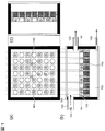
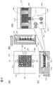
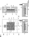
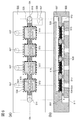
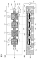
- FIG. 2 is a diagram showing a basic configuration of a device described in Patent Document 1, which is a related technique of the present invention. It is a figure showing an embodiment of composition of a cell analysis device concerning one mode of the present invention. It is a figure which shows embodiment of the structure of the cell analysis device which concerns on another aspect of this invention. It is a figure which shows the flowchart and separation timing of the cell analysis method using the cell analysis device which concerns on this invention.
- FIG. 3 is a diagram showing an outline of the configuration of a device manufactured in Example 1-1. It is a figure which shows the nucleic acid processing process in the analysis method using the cell analysis device which concerns on this invention.
- FIG. 6 is a diagram showing an outline of the configuration of a device manufactured in Example 1-4.
- FIG. 6 is a diagram illustrating an outline of a configuration of a device according to Example 2. This is a continuation of FIG. 8-1. It is a figure which shows the outline
- FIG. 6 is a diagram illustrating an outline of a configuration of a device according to Example 3.
- the cells when the cells are aspirated to the cell capturing part of the 2D array chip, the cells are aspirated by competing with the repulsive force (for example, gravity) in the direction of separating the cells from the substrate of the 2D array chip. This prevents the cells from adsorbing to the two-dimensional array chip.
- the repulsive force for example, gravity
- the cell analysis device of the present invention includes a solution introduction channel for introducing a solution containing cells, a cell capture unit having a recess in contact with the solution introduction channel and capable of capturing one cell, A substrate provided corresponding to each concave portion of the cell trapping part, and provided with a plurality of sets of nucleic acid trapping parts that trap nucleic acids extracted from the cells trapped by the cell trapping part, and the nucleic acid trapping of the substrate And a pressure control means provided in the discharge channel, the substrate having a repulsive force in a direction in which the cells are separated from the substrate.
- the pressure control means when capturing cells in the cell capture unit, the force in the direction from the cell capture unit to the nucleic acid capture unit is a first pressure greater than the repulsive force It is something to control.
- FIG. 2A and 2B are diagrams showing an embodiment of the configuration of the cell analysis device according to the above aspect of the present invention, in which FIG. 2A is a bottom view (a plan view seen from the bottom), and FIG. (C) shows a cross-sectional view of the 2B-2B ′ cross-section. Further, (d) is an enlarged view of a region 2C in the sectional view (c).
- the cell analysis device includes a plurality of cell capture units 203 capable of capturing cells one by one, and nucleic acids that are present corresponding to each cell capture unit and extracted from the cells captured by the cell capture unit.
- a lower region 214 having a substrate (hereinafter referred to as a two-dimensional array chip (213)) having a set of nucleic acid capturing units 210 to capture and holding a cell solution introduced from the cell introduction port 211 before suction is two-dimensional.
- the upper region 215 opposite to the array chip is connected to the upper outlet 207 at the top.
- a pump or syringe is connected to the upper outlet 207.
- a negative pressure By applying a negative pressure to the upper outlet 207, a negative pressure can be applied to the nucleic acid capturing unit 210 and the cell capturing unit 203 on the two-dimensional array chip.
- the cell solution in the region 214 is sucked into the cell trap 203.
- a force acts on the cell upward (in the direction of arrow 216) due to the viscosity of the solution when the cell solution is sucked.
- gravity works in the 217 direction and is opposite to the suction direction.
- the nucleic acid capturing unit 210 is composed of a porous material or beads (preferably magnetic beads), and a nucleic acid probe for capturing nucleic acids extracted from cells is fixed.
- the nucleic acid probe has a nucleic acid capture sequence that hybridizes with a nucleic acid extracted from a cell and a different cell recognition sequence corresponding to each cell capture portion, and amplifies the nucleic acid captured by such a nucleic acid probe. Single cell analysis becomes possible by using the obtained product.
- Nucleic acid probes can be appropriately designed by those skilled in the art depending on the purpose of analysis, the analysis target (mRNA, genomic DNA, ncRNA, etc.), the configuration of the device used, the type of amplification reaction, and the like.
- the cell solution is introduced from the cell introduction port 211.
- the single cell is adsorbed to the cell trap 203 by sucking the solution from the upper outlet 207 and applying a negative pressure, which is the same as in the conventional device.
- the device according to the present invention is different from the conventional device in that the direction of gravity is controlled to an appropriate direction.
- the suction force approaching the two-dimensional array chip during cell aspiration must be stronger than the gravity applied in the opposite direction.
- This strong suction is particularly effective when the negative pressure applied to the upper outlet is close to 1 atm, and the pressure inside the region 215 is set lower than the saturated vapor pressure of the cell solution.
- a continuous suction pump such as a diaphragm pump is more effective than a pump using a syringe with a finite suction volume.
- Another method for realizing a strong suction force to overcome gravity is a method of arranging a three-dimensional porous body.
- the three-dimensional porous body When the three-dimensional porous body is arranged in the region 215, it quickly absorbs the aqueous solution contacted by capillary action, and discharges the absorbed aqueous solution to the outside, particularly in a direction not in contact with the nucleic acid capturing unit 210. It has the property that can be made. By discharging the absorbed aqueous solution, the solution absorption performance by capillary action of the three-dimensional porous body can be maintained. By utilizing the capillary phenomenon of the three-dimensional porous body, the solution staying in the nucleic acid capturing unit 210 is sucked more quickly than in the case of simply applying a negative pressure as in the conventional example shown in FIG. In addition, the ability of the cell capture unit 203 to adsorb cells can be improved.
- the embodiment using a three-dimensional porous material will be described in detail in the description of the configuration for recovering a nucleic acid amplification product with high efficiency when nucleic acid amplification is performed in the device.
- the force applied to the cells in the direction of separating the cells from the two-dimensional array chip is not limited to gravity.
- a repulsive force is applied to the cell in the vicinity of the 2D array chip, and the cell is transferred to the 2D array chip. Adsorption can be suppressed. It can also be realized by coating the surface with a coating agent such as MPC polymer or polyethylene glycol.
- a three-dimensional porous body is arranged adjacent to the two-dimensional array chip to accelerate the suction of the cells by capillary action, and the effect of sedimentation due to the gravity of the cells. It is to reduce.
- the amplified product on the two-dimensional array chip is not adsorbed on the three-dimensional porous body. And a means for separating the three-dimensional porous body.
- the cell analysis device of the present invention includes a solution introduction channel for introducing a solution containing cells; a plurality of cell traps provided adjacent to the solution introduction channel and capable of capturing cells one by one
- a two-dimensional array chip provided with a portion and a nucleic acid capturing portion that is provided corresponding to each cell capturing portion of the plurality of cell capturing portions and captures nucleic acid extracted from the cells captured by the cell capturing portion;
- a three-dimensional porous body that absorbs the solution staying in the nucleic acid capture unit, and a discharge channel that discharges the solution; a separation control unit that controls separation between the nucleic acid capture unit and the discharge channel;
- the separation control unit performs separation control so that a product amplified from the captured nucleic acid is not introduced into the discharge channel after the nucleic acid is captured by the nucleic acid capturing unit.
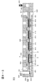
- FIG. 3 is a diagram showing an embodiment of the configuration of the cell analysis device according to the above aspect of the present invention, in which (a) is a bottom view (a plan view seen from below), and (b) is a cross section taken along the 3A-3A ′. Cross-sectional views, (c) and (d) show cross-sectional views in the 3B-3B ′ cross-section, respectively.
- the cell analysis device relates to a configuration provided with means for efficiently recovering an amplification product from a nucleic acid extracted from a cell to the outside. 2 provided with a plurality of cell capture units 303 capable of capturing cells one by one, and a nucleic acid capture unit 310 that captures nucleic acids extracted from the cells captured by the cell capture unit corresponding to each cell capture unit
- the three-dimensional array chip (313) is the same as in the above embodiment, and the lower region 314 holding the cell solution introduced from the cell introduction port 311 is disposed adjacent to the two-dimensional array chip, and the upper region 315 on the opposite side is The same applies to the connection to the upper outlet 307.
- a pump or a syringe is connected to the upper outlet 307.
- a negative pressure is applied to the upper outlet 307, a negative pressure is applied to the nucleic acid capturing unit 310 and the cell capturing unit 303 on the two-dimensional array chip.
- the cell solution in the region 314 is sucked into the cell trapping portion 303.
- a means for separating the three-dimensional porous body and the two-dimensional array chip is provided in the configuration in which the suction force is increased by arranging the three-dimensional porous body in the upper region and the cells are captured.
- This separation means includes "for" 323 in FIG.
- a syringe 333 is provided as means for injecting air or a separation solvent.
- the two-dimensional array chip is made of an elastic material (here, PDMS resin), by applying a negative pressure for suction to the upper outlet 307, (C) in FIG.
- the two-dimensional array chip bends and adheres to the three-dimensional porous body 319 by applying a negative pressure. By such close contact, the three-dimensional porous body can be sucked by the capillary effect.
- a bead outflow prevention film (hydrophilic porous film) 318 is added to the two-dimensional array chip 313. It is in close contact with the back side. The close contact between the three-dimensional porous body and the two-dimensional array chip is accurately realized by close contact between the bead holding film 318 and the three-dimensional porous body.
- the bead outflow prevention film 318 functions integrally with the two-dimensional array chip 313, suction by the capillary effect is effective.
- an actuator can be connected to the three-dimensional porous body to change the distance between the three-dimensional porous body and the two-dimensional array chip.
- an isolation film that prevents the amplification product from reaching the surface of the three-dimensional porous body while keeping in close contact. This is achieved, for example, by placing a pore sized ultrafiltration membrane or gel membrane between the 3D porous body and the 2D array chip to prevent the molecular size molecules (eg DNA molecules) of the amplification products from passing through.
- the three-dimensional porous material used in the present invention has a surface hydrophilicity enough to absorb aqueous solution by capillary action caused by the presence of pores randomly having pores of several tens of nm to several ⁇ m of zero points. It is the material which has. Specific examples thereof include a porous glass material, a glass fiber aggregate (for example, a bundle of glass fibers aligned in the same direction), and a glass bead aggregate (with an average particle size in the range of 0.1 to 30 ⁇ m). Preferred). It is preferable that the three-dimensional porous body is not easily deformed because the absorbed solution is unlikely to be unintentionally discharged and flows back to the nucleic acid capturing unit 310 or the cell capturing unit 303.
- the hydrophilicity of the surface of the three-dimensional porous body has a water contact angle measured using pure water of 90 ° or less, preferably 80 ° or less, more preferably 50 ° or less, particularly preferably 40 ° or less, Alternatively, when 1 ⁇ L of pure water is dropped on a three-dimensional porous body having a volume sufficient to hold 1 ⁇ L of liquid, it is within 10 seconds, preferably within 5 seconds, more preferably within 3 seconds, particularly preferably. It can be characterized by any of the absorption of drops dropped within 1 second. In addition, when the liquid droplet is absorbed by the three-dimensional porous body, it means that the presence of the liquid droplet cannot be visually confirmed when observed from a plane perpendicular to the surface of the three-dimensional porous body. To do.
- the three-dimensional porous body constituting the solution holding unit 319 is preferably sufficiently larger than the pores of the nucleic acid capturing unit 310 made of a porous membrane, beads, etc., for example, the average pore size is 0.2 ⁇ m or more, In particular, it is preferably 3 ⁇ m or more. With such a size, an excessively large pressure loss does not occur when a gas such as air passes through the solution holding unit 319. Further, if the pore size of the three-dimensional porous material is as described above, a sufficient pressure difference is generated between the upper part and the lower part of the nucleic acid capturing part 310 when a negative pressure is applied from the upper outlet 307. Can do.
- the flow path provided with the solution holding unit 319 and communicated with the upper outlet 307 is also communicated with the intake port 321 opened to the outside of the apparatus via the pressure adjusting member 320.
- the intake port 321 is released to the outside in the upper part direction of the apparatus.
- the intake port 321 when negative pressure is applied from the upper outlet 307, outside air is taken in from the intake port 321 via the pressure adjusting member 320, and an air flow 322 is generated, thereby the solution holding unit 319.
- the solution absorbed in is discharged.
- the solution holding unit 319 absorbs the solution by capillary action only when negative pressure is applied from the upper outlet 307, that is, the volume of the solution discharged by the solution holding unit 319. Only by capillary action can the solution be absorbed again. Further, in the case of a configuration in which the intake port 321 is not provided, if the upper region 314 is simply filled with the solution, the solution may not reach the solution holding unit 319 and absorption may not start. Absorption does not stop until the capacity of 319 is satisfied and the controllability becomes insufficient, but the controllability can be supplemented by providing the intake port 321. It is preferable to further provide an air valve at the intake port 321 because controllability of solution absorption is further improved.
- the pressure adjusting member 320 causes a pressure loss larger than that generated when the solution passes the nucleic acid capturing unit 310 when the gas passes.
- the pressure adjusting member 320 for example, a material having pores finer than the holes of the nucleic acid capturing unit 310, for example, about 1/5 to about 1/10 of the average pore diameter of the holes of the nucleic acid capturing unit 310, more preferably about If a material having an average pore diameter of 1/7 to about 1/9, specifically about 1/8, is used, it can be said that the balance is good from the viewpoint of the difference in viscosity between air and water.
- FIG. 4 shows a flow diagram of a cell analysis method using the device according to the present invention. This will explain at what timing the three-dimensional porous body and the two-dimensional array chip are separated.
- the extracted nucleic acid (for example, mRNA) is captured by a nucleic acid probe fixed to the nucleic acid capturing unit 310.
- the nucleic acid captured on the surface of the nucleic acid capture unit 310 in (Step 3) can be obtained by introducing a reagent containing an enzyme into the nucleic acid capture unit so that the first strand (eg, cDNA) complementary to the captured nucleic acid (eg, mRNA) Synthesized.
- a second DNA strand is synthesized by introducing a second DNA probe and an enzyme reagent corresponding to the gene to be measured into the nucleic acid capture unit. All the reactions up to this point occur on the surface of the nucleic acid capturing part, and necessary reaction products are immobilized on the surface. In subsequent amplification reactions (eg, PCR), the amplification product is released from the surface and is recovered from the device as the final product. At this time, in order to prevent the amplification product from adsorbing to the three-dimensional porous body wall, a reagent containing an enzyme and a substrate necessary for the amplification reaction is introduced into the nucleic acid capture unit by suction, and then the suction force is turned off.
- a reagent containing an enzyme and a substrate necessary for the amplification reaction is introduced into the nucleic acid capture unit by suction, and then the suction force is turned off.
- the separation air or the separation solvent is injected between the three-dimensional porous body and the two-dimensional array chip by pushing the syringe 333 from “for” 323. This prevents the amplification product from moving from the two-dimensional array chip to the three-dimensional porous body, thereby preventing adsorption. During amplification, the amplification product spreads from the two-dimensional array chip to the region 314 by diffusion.
- the timing of separation by injection of air or separation solvent may be the timing before the amplification reaction (for example, PCR cycle reaction) after the introduction of the reagent, but amplification for several cycles before moving from the nucleic acid capture part to the three-dimensional porous material by diffusion. It is better to separate after the reaction is complete. By executing at such timing, the influence of the movement of the solution due to the temperature change can be minimized.
- amplification reaction for example, PCR cycle reaction
- the amplification product is collected from the sample collection port 312 by suction.
- the cell introduction port 311 is open, and the solution moves from 311 toward 312. Since the obtained amplification product contains DNA strands that are unnecessary for analysis (especially short DNA strands), purification was performed to remove them in (Step 7), and next generation in (Step 8). Perform sequence analysis with the sequencer. Finally, it is the same as in the conventional example to obtain a single cell analysis result by regrouping the sequences obtained for each tag sequence corresponding to the cell capture position (Step 9).
- the amplification of the nucleic acid is preferably PCR amplification, but is not limited thereto, and other amplification methods such as rolling circle amplification (RCA) reaction, NASBA method, LAMP method can be used.
- RCA rolling circle amplification
- NASBA NASBA method
- LAMP LAMP method
- the separation is executed at the same timing as above.
- the movement of the amplification product to the porous body is always blocked, so there is no need to set the separation timing.
- the pore size of the ultrafiltration membrane or gel membrane is set to 1 to 10 nm, for example, 5 nm (30 kDa), so that the amount of nucleic acid transferred by the amplification product without negative pressure is reduced to 1/10 The following can be reduced.
- FIG. 5 is a diagram showing an outline of the configuration of the device manufactured in this example, (a) is a bottom view (plan view from below), (b) is a diagram Sectional drawing in a 5A-5A 'cross section is shown.
- the device 500 includes a plurality of reaction chambers 524, and each of the reaction chambers 524 includes a plurality of cell capture units 503 and a set of nucleic acid capture units 510 corresponding to the individual cell capture units 503.
- a dimension array chip 513 is arranged.
- the cell solution is supplied onto the two-dimensional array chip 513 by flowing through the common channel 525 from the cell introduction port 511 toward the sample recovery port 512, and the chip solution is filled with the cell solution.
- the individual inlet 527 is used when a reagent is individually introduced into a chip, specifically, for example, when a reagent including a primer having a tag sequence for identifying a chip is introduced.
- the two-dimensional array chip 513 For the production of the two-dimensional array chip 513, a resin chip made of dimethylpolysiloxane (PDMS) obtained by injection molding (a square with a side of 1.125 mm) is used, and a through hole with a diameter of about 3 to 10 ⁇ m smaller than the cell is formed. Thus, a cell capturing unit 503 was obtained.
- the two-dimensional array chip may be manufactured using a resin chip obtained by injection molding using another resin (polycarbonate, cyclic polyolefin, polypropylene, etc.), or using a nanoimprint technology or a semiconductor process. Can also be done.
- the material used for manufacturing the two-dimensional array chip is preferably a hydrophobic material, which can reduce adsorption of cells, reagents, and the like on the array chip.
- a repulsive force can also be applied to the cells by performing a treatment for suppressing the adsorption of the cells on the surface of the substrate of such a two-dimensional array chip (see Example 1-3).
- the filling of magnetic beads is performed individually using an ink jet printer head. In a state where the chip is turned upside down, 2 nL of the bead solution in which different sequences are fixed for each region is individually filled in the nucleic acid capturing unit 510. In the bead solution used for filling, magnetic beads having a diameter of 1 ⁇ m are suspended at a number density of 5 ⁇ 10 9 particles / mL.
- Streptavidin is immobilized on the magnetic beads, and a 5 'biotin group-modified DNA probe is immobilized via this streptavidin.
- the bead diameter was set to several ⁇ m or less (for example, 1 ⁇ m or less).
- a bead outflow prevention film 518 resin porous film having a pore diameter of 0.8 ⁇ m: Isopore film, manufactured by Millipore having a pore diameter smaller than the bead diameter was brought into close contact with the two-dimensional array chip 513 so that the filled magnetic beads did not flow out.
- gravity is used as the repulsive force, and the cells are prevented from coming into contact with and adsorbing to areas other than the cell trapping portion on the two-dimensional array chip due to the sedimentation of the cells due to gravity.
- gravity works in a direction away from the two-dimensional array chip, it is necessary to overcome the gravity and suck cells.
- the nucleic acid capture unit 510 of the two-dimensional array chip 513 is filled with fine magnetic beads, a cell solution is sufficient by simply applying a pressure difference between the upper and lower parts of the two-dimensional array chip 513 using a syringe. It may not flow at a flow rate and a sufficient suction force may not be obtained.
- the suction method is not a syringe, but a diaphragm pump is connected to the upper outlet, so that the region of the upper channel 526 is kept below the saturated vapor pressure of the aqueous solution, and the two-dimensional array chip This was realized by evaporating the solution that reached the backside of the plate and quickly discharging it. Evaporating the solution in this way promotes the capillary effect of the nucleic acid capturing unit, thereby realizing high-speed suction and capturing cells against gravity.
- FIG. 4 is a flowchart showing an outline of a single cell analysis method using the device of the present invention produced in Example 1-1 shown in FIG. FIG.
- Step 1 cell capture, (Step 2) cell lysis (disruption), (Step 3) complementary strand (1st strand) synthesis (eg, cDNA synthesis), (Step 4) capture nucleic acid degradation (eg, mRNA degradation) ), (Step 5) 2nd strand synthesis, and (Step 6) amplification reaction are performed in the device.
- the reaction up to (Step 5) is a solid-phase reaction in which the reaction product is immobilized on the nucleic acid capturing unit 510.
- the amplification product released from the two-dimensional array chip in (Step 6) diffuses into the reaction reagent in the reaction chamber 524. After completion of the amplification reaction, the reagent containing this amplification product is recovered from the sample recovery port 512 by aspiration.
- Step 4 After completing the complementary strand (1st strand) synthesis (for example, cDNA synthesis) of (Step 4), remove the 2D array chip from the device and submerge the chip in the tube containing the reagent, so that the beads are in solution. (Step IV5) and subsequent reactions may be carried out in the tube (outside the device).
- Step 7) is a purification step that removes by-products during amplification that are unnecessary for nucleic acid sequence analysis.
- Step 8) is a sequence analysis step by a next-generation sequencer, and any sequence analysis platform may be used as long as the sequencer has a high degree of parallelism.
- the last (Step 9) is a data analysis step, in which sequence analysis results are compiled for each cell identification tag and chip tag, and gene analysis data for each single cell is constructed.
- a step of capturing the cells in the cell solution by the cell capturing unit 503 on the two-dimensional array chip 513 is performed.
- the cell solution is introduced from the cell introduction port 511 and sucked from the sample collection port 512 to fill the two-dimensional array chip 513 with the cell solution.
- the cell solution passes through the cell capturing unit 503 and the nucleic acid capturing unit 510 on the two-dimensional array chip 513, and the cells are captured by the cell capturing unit 503.
- Reference numeral 501 in FIG. 5 (a) denotes a cell captured by the cell capturing unit.
- the lysis buffer is introduced from the cell inlet 511 and sucked from the sample collection port 512, so that the lysis buffer fills the 2D array chip 513 and obtains the required suction speed. Apply negative pressure to 507.
- the negative pressure to be applied was the same as that during cell aspiration. In order to completely complete cell aspiration, it was effective to introduce about 1 ⁇ L of PBS buffer before introducing the lysis buffer.
- the step of complementary strand (1st strand) synthesis (for example, reverse transcription, cDNA synthesis).
- the negative pressure value is reset so that the necessary introduction rate of the complementary strand synthesis (reverse transcription) reagent mix can be obtained.
- the reagent is introduced from the cell introduction port 511, and the two-dimensional array chip 513 is filled with the reagent.
- the temperature of the device is raised and maintained for the time required for the reaction. Further, the temperature is raised to 85 ° C. in order to inactivate the reagent (for example, reverse transcriptase).
- the washing buffer is introduced from the cell introduction port 511, and the negative pressure is reset in order to introduce and remove the washing buffer from the nucleic acid capturing unit.
- capture nucleic acid degradation (mRNA degradation) and 2nd strand synthesis are almost the same as the complementary strand (1st strand) synthesis (reverse transcription) step.
- the last step is an amplification reaction.
- the amplification reaction reagent mix is introduced into the cell introduction port 511, and the negative pressure is set so that the reagent mix is introduced into the nucleic acid capturing unit 510 at a necessary solution speed.
- FIG. 6 shows how a sample is prepared by processing a nucleic acid (for example, mRNA) captured by the nucleic acid capturing unit 510 of the device of this example.
- a nucleic acid for example, mRNA
- This step involves cell disruption after cell capture (Step 1) and capture of nucleic acid (mRNA) (Step 2) and synthesis of complementary strand (1st strand) (eg cDNA) (Step 3) and capture nucleic acid (eg mRNA) ) Degradation (Step 4), nucleic acid amplification (PCR) and synthesis of 2nd ⁇ ⁇ strand that introduces known terminal sequences necessary for sequencing (Step 5), and nucleic acid amplification (Step 6-1) (Step 6-2) Divided into steps.
- the cells are trapped here. Since the trapped cells act as plugs for the solution flow, the solution flow moves to the cell trapping portion 503 that has not yet trapped the cells. Therefore, the remaining cells are moved to and captured by the capturing unit where the cells are not yet captured.
- a lysis buffer for example, a surface active agent such as Tween 20
- a surface active agent such as Tween 20
- the bead outflow prevention membrane 518 is a flow path made of a porous material having a diameter of 0.8 ⁇ m and has a large pressure loss.
- the trapped cell 501 is crushed by the lysis buffer, and the nucleic acid 606 (for example, mRNA) goes out of the cell, but the flow of the cell solution around the cell trapping part 503 is sucked into the holes constituting the cell trapping part 503.
- the nucleic acid 606 (for example, mRNA) reaches the nucleic acid capturing unit 510 through the cell capturing unit 503 without diffusing to the periphery.
- cell disruption and capture of the nucleic acid 606 (for example, mRNA) by the first DNA probe 601 immobilized on the beads of the nucleic acid capture unit 510 are simultaneously performed. This is shown in Step 2 of FIG.
- the information on the position on the two-dimensional array chip 513 where the cells are trapped that is, the position coordinates of the cell trapping portions 503 arranged in a lattice pattern as shown in FIG. Therefore, on the bead surface of the nucleic acid capturing unit 510, a first DNA probe 601 having a cell recognition sequence 602 having a different sequence for each cell capturing unit 503 is fixed.
- the diagonal line at the left end of each step diagram indicates the fixed wall surface, here, the bead surface.
- This first DNA probe 601 has a sequence complementary to the nucleic acid to be captured at the 3 ′ end region (for example, when capturing mRNA, a poly T sequence), and the sequence of the nucleic acid to be captured Nucleic acid 606 (eg, mRNA) is captured by hybridizing to (eg, hybridizing to the poly A sequence at the 3 ′ end of the mRNA). Further, a common primer (604, Reverse) for amplification reaction may be provided on the 5 ′ end side.
- the first DNA probe 601 is composed of a common primer for amplification of about 30 bases from the 5 ′ end (604, Reverse), a cell recognition sequence of about 7 bases (602), and an oligo of about 18 bases ( dT) Sequence + VN sequence of 2 bases.
- a poly-T sequence was used as part of the capture DNA probe 601 to analyze mRNA, but in order to perform microRNA and genome analysis, the sequence of the nucleic acid to be analyzed was replaced with the poly-T sequence.
- a part of the complementary sequence or a random sequence can be used, and the sequence design of such a capture probe can be appropriately performed by those skilled in the art based on conventional techniques.
- 1st strand 607 is synthesized using the nucleic acid (mRNA) 606 captured by the first DNA probe 601 as a template.
- mRNA nucleic acid
- a synthesis reagent eg, reverse transcriptase
- the complementary strand synthesis reaction (1st-strand synthesis reaction) was carried out for about 50 minutes after heating.
- nucleic acids for example, cDNA
- cDNA single-cell nucleic acid
- a synthesis reagent eg, reverse transcriptase
- a nucleic acid library array for example, a cDNA library array, corresponding to all the cells for each captured cell is constructed as shown in Step IV 4 of FIG.
- Ex Taq ⁇ Hot start version (TaKaRa Bio) with 69 ⁇ L of sterilized water, 10 ⁇ L Ex Taq Buffer (TaKaRa Bio) 10 ⁇ L, 2.5mM dNTP Mix 100 ⁇ L, and 10 ⁇ M of each common sequence for amplification (Reverse) 609 was added. ) 1 ⁇ L was mixed, and this mixed reagent was introduced from the upper inlet 511 to the nucleic acid capturing unit 510 in the same manner as in the previous step. A method for individually introducing the second DNA probe 608 with the chip identification tag 610 will be described later. Thereafter, the secondary structure of the nucleic acid was solved at 95 ° C.
- Step 5 in FIG. 6 shows that the second DNA probe 608 is hybridized to 1st strand and synthesizes 2nd strand 612.
- the complementary strand extension reaction is completed by raising the temperature to 72 ° C. for 6 minutes.
- the introduction of the second DNA probe 608 into the reaction chamber 524 is performed as follows. First, mineral oil is introduced from the cell inlet 511 and discharged from the upper outlet 512. Next, a buffer solution containing a reagent is flowed from the upper channel 526 toward the individual inlet 527, and excess mineral oil in the reaction chamber is discharged from the individual inlet 527. By doing so, the region filled with the buffer solution in the reaction chamber 524 below the two-dimensional array chip 513 is separated by mineral oil. Such separation occurs because the inner wall of the reaction chamber 524 is hydrophilic while the surface treatment is performed so that the region 528 between the reaction chambers is hydrophobic.
- the 1st strand is firmly fixed to the beads (for example, by a biotin-avidin bond) in order to maintain high reaction efficiency.
- a buffer solution containing a second DNA probe having a different chip identification sequence is introduced from the individual inlet 527 and discharged from the upper outlet 512 through the upper channel 526.
- the vicinity of the nucleic acid capture unit 510 is filled with the second DNA probe that is different for each reaction chamber 524, and this probe hybridizes in 1st strand.
- the last step is an amplification reaction using a common primer as shown in Steps 6-1 and 6-2 in FIG.
- PCR reaction was performed, sterilized water 49 ⁇ L, 10 x High Fidelity PCR Buffer (Invitrogen) 10 ⁇ L, 2.5 mM dNTP mix 10 ⁇ L, 50 mM MgSO4 4 ⁇ L, 10 ⁇ M PCR amplification common primers (Forward) 10 ⁇ L
- a reagent was prepared by mixing 10 ⁇ L of a sequence primer (Reverse) and 1.5 ⁇ L of Platinum Taq Polymerase High Fidelity (Invitrogen), and then introduced from the cell inlet 511 as in the previous step.
- the amplification step was performed after cooling.
- This reaction is a common reaction, and the amplification efficiency can be made uniform between the chips by performing the amplification reaction under the same conditions for all the chips.
- the amplification product solution accumulated in the solution is collected, and for the purpose of removing residual reagents such as free common sequence primers (Forward / Reverse) and enzymes contained in this solution, for example, PCR Purification Kit (QIAGEN) ).
- the obtained amplification product 615 is a sequence that can be sequenced and is called a sequencing library. Even if an amplification bias occurs between genes or molecules in the above-mentioned process, high-accuracy quantitative data can be obtained because the amplification bias can be corrected using molecular recognition tags after acquiring sequencing data. Can do.
- a gene expression level can be obtained for each cell identification sequence and chip identification sequence. That is, it is possible to simultaneously analyze the number of cells equal to or less than the product of the type of the cell identification sequence and the type of the chip identification sequence simultaneously introduced into the device. As a result, it is possible to analyze the number of cells significantly larger than the number of cell identification sequences introduced in advance into the two-dimensional array chip.
- a two-dimensional array chip can be fabricated using PDMS resin. Before injecting the beads constituting the nucleic acid capture unit, the surface of the 2D array chip (substrate) made of PDMS resin is coated to separate the cells from the 2D array chip (substrate) in the vicinity of the 2D array chip surface. A repulsive force works in the direction, and the adsorption of cells to the chip surface can be suppressed.
- MPC (2-methacryloyloxyethyl phosphorylcholine) polymer (Nippo Lipidure (registered trademark) -CM5206) was coated, and the cell adsorption rate could be reduced to 1/10 or less.
- a coating method a 0.5 w% ethanol solution was prepared, 2 ⁇ L per chip was dropped onto a PDMS resin film, the chip was covered with the solution, and left for 5 minutes, and the chip was collected. The structure of the device was the same as in FIG. 5, and almost no cells were adsorbed, and more than 95% of cells were recovered in all chips.
- coating agents based on PEG (polyethylene glycol) (Block Master manufactured by JSR Life Sciences), and any coating agent may be used.
- FIG. 7 shows a configuration in which repulsion is applied to the cells using dielectrophoresis to reduce the adsorption of the cells to the two-dimensional array chip.
- the difference from the basic configuration shown in FIG. 5 is that electrodes for dielectrophoresis are arranged on the top and bottom, that the beads of the nucleic acid capturing part are made of metallic gold fine particles instead of magnetic beads, and that a high frequency power source is used. It is arranged.
- the electrode configuration for suppressing cell adsorption is as follows.
- the upper electrode 729 is disposed in the upper flow path 726 and is a flat plate substrate made of platinum. As many as 1.1 mm square electrodes, which are arranged immediately above the two-dimensional array chip and have the same size as the two-dimensional array chip, are connected in series by the number of chips.
- the electrode thickness was 0.1 mm. In the method of use in this embodiment, since the applied voltage is low, the possibility of corrosion is low, and the material may be a metal other than platinum.
- wires having a diameter of 0.1 mm were arranged in a lattice shape, and an electrode structure was formed by ultrasonic welding.
- Fig.7 (a) it has arrange
- the nucleic acid capturing unit 731 was packed with gold fine particles having a diameter of 400 nm, and a DNA probe was immobilized on the surface thereof using a thiol group.
- an attractive force acts toward the cell capturing part by dielectric bonding.
- the alternating voltage applied to both electrodes from the high frequency power source 732 was a sine wave of 10 Vpp at several kHz, and a frequency lower than the frequency at which the dielectric attractive force was inverted to the dielectric repulsive force was applied.
- the frequency may be higher than several MHz (this frequency varies depending on the cell size and dielectric constant), and the dielectric force may be repulsive and antagonized with the attractive force.
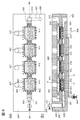
- FIG. 8 is a diagram showing an outline of the configuration of a device according to another aspect of the present invention, where (a) is a top view, and (b) is a cross-sectional view in the 8A-8A ′ cross section, showing the configuration during cell solution aspiration. Show.
- FIG. 8C shows a cross-sectional view when the three-dimensional porous body and the two-dimensional array chip are separated during the amplification reaction.
- gravity and suction force are not installed in opposite directions as in Example 1 (may be installed in opposite directions), and the suction force is increased by using a three-dimensional porous body, and gravity It is the structure which suppresses the influence of the sedimentation by minimum.
- FIG. 8 (b) is a cross-sectional view of the device during cell capture.
- the two-dimensional array chip 813 is made of a flexible PDMS resin, and a resin porous membrane (Isopore membrane having a pore diameter of 0.8 ⁇ m) is used as a bead outflow prevention film 818 for preventing outflow of beads forming the nucleic acid capturing unit 810. , Manufactured by Millipore).
- the device 800 includes a plurality of reaction chambers 824, and each of the reaction chambers 824 includes a two-dimensional array including a plurality of cell capture units 803 and a nucleic acid capture unit 810 corresponding to each of the cell capture units 803.
- a chip 813 is arranged.
- the cell solution is supplied onto the two-dimensional array chip 813 by flowing through the common channel 825 from the cell introduction port 811 toward the sample collection port 812, and the chip solution is filled with the cell solution.
- the individual inlet 827 is used when a reagent is individually introduced into a chip, specifically, for example, when a reagent including a primer having a tag sequence for identifying a chip is introduced.
- a porous shirasu sintered body (shirasu porous glass: SPG film, manufactured by SPG Techno Co.), which is a three-dimensional porous body, was disposed, and a solution holding unit 819 was obtained.
- the lower flow path 837 communicates with the lower outlet 838 and the intake port 835 for taking in air, and in the vicinity of the intake port 835, a pressure adjustment filter 836 (in this embodiment, taking into account the difference in viscosity between water and air, A resin porous membrane (Isopore membrane, manufactured by Millipore) having a pore size of 0.1 ⁇ m and an air valve 834 were provided.
- a resin porous membrane Isopore membrane, manufactured by Millipore
- the two-dimensional array chip 813 is filled with the cell solution, and then a negative pressure is applied by a syringe pump connected to the lower outlet 838 with the air valve 834 opened.
- a syringe pump may be used instead of the syringe pump.
- the two-dimensional array chip By applying a negative pressure to the lower outlet 838, the two-dimensional array chip is bent, and the bead outflow prevention film 818 and the three-dimensional porous body (819) are brought into close contact with each other. Thereby, the cell solution can be sucked at high speed by utilizing the capillary effect of the three-dimensional porous body.
- position A upper part of the two-dimensional array chip 813
- position B lower flow path 837 between the solution holding unit 819 and the pressure adjustment filter 836
- position C (2 Dimensional array chip 813 and solution holding part 819)
- the pressure relationship at position D is the magnitude relationship of A >> B> C> D
- the suction force due to this capillary phenomenon generates a suction force of about 100 kPa in the cell trapping part 803 (assuming a circular shape with a diameter of 5 ⁇ m) in the configuration of this example. Can be calculated. As a result, the cells can be sucked almost without being affected by sedimentation due to gravity.
- the air taken in from the intake port 835 passes through the solution holding part 819 due to the pressure difference between the position B, the position C, and the position D, whereby the aqueous solution absorbed by the solution holding part 819 is discharged toward the position D.
- the By this discharge the suction force due to the capillary action of the solution holding unit 819 is recovered, so that the suction force of the solution holding unit 819 continues as long as the suction from the lower outlet 838 continues.
- the suction from the lower outlet 838 stops the inner wall of the three-dimensional porous body constituting the solution holding portion 819 is quickly covered with the aqueous solution, and the suction force is lost.
- the reaction chamber 824 is filled with reagents for amplification reaction (PCR reaction), and then a negative pressure is applied to the lower outlet 838 to introduce the amplification reagent (PCR reagent) into the nucleic acid trap.
- PCR reaction reagents for amplification reaction
- the syringe 833 is pushed in, and the mineral oil accumulated in the bottle 823 is slowly injected between the bead outflow prevention membrane 818 and the three-dimensional porous body in about 10 seconds.
- the three-dimensional porous body is highly hydrophilic, mineral oil, which is a nonpolar solvent, does not infiltrate into the porous body. In this way, as shown in FIG.
- the amplification reagent (PCR reagent) solution remaining in the three-dimensional porous body is isolated from the amplification reagent (PCR reagent) in the nucleic acid capturing part in the two-dimensional array chip. can do.
- air is used instead of mineral oil, the air enters the three-dimensional porous body, and the amplification reagent (PCR reagent) solution can be isolated from the two-dimensional array chip.
- Example 2-2 Separation by a moving mechanism of a three-dimensional porous body
- a nonpolar solvent or oil was injected for separation, but in this example, a three-dimensional porous body and two-dimensional It is also possible to separate the solution by separating the array chip from each other at an appropriate timing.
- a mechanism for movement may be inserted immediately below the three-dimensional porous body.
- an example using air pressure is shown, but a moving mechanism such as a servo mechanism may be used.
- Fig. 9 shows a configuration for separating a two-dimensional array chip and a three-dimensional porous body by air pressure.
- Reference numeral 939 denotes an airbag made of polyethylene resin. The size is about 1x1mm, similar to the two-dimensional array chip.
- a pump such as a syringe 940
- the thickness of the airbag can be reduced to about 0.1mm to 0.3mm. Designed to change.
- the two-dimensional array chip and the three-dimensional porous body are in close contact with each other, and the solution can be sucked by the capillary effect.
- the internal pressure of the airbag 939 is reduced and the thickness is reduced, so that the three-dimensional porous body is separated from the two-dimensional array chip.
- amplification reagent PCR reagent
- increase the internal pressure of the airbag, and reduce the internal pressure of the airbag after the start of the amplification reaction (for example, PCR cycle) to the three-dimensional porous body wall of the amplification product Can be prevented.
- an ultrafiltration membrane having a pore size of about 5 nm may be used instead of 0.8 ⁇ m pore ISOPORE.
- the two-dimensional array chip and the three-dimensional porous body remain in close contact with each other, but since the application of negative pressure is turned off during the amplification reaction, the speed at which the amplification product passes through the ultrafiltration membrane is greatly increased. Can be lowered. This can also prevent the amplification product from adsorbing to the three-dimensional porous material.
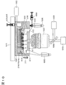
- Example 3 In this example, an apparatus configuration in which the device configuration of Example 1 is combined with a fluorescence microscope for observing captured cells will be described.
- Figure 10 shows the configuration diagram.
- the configuration of the device 1001 is the basic configuration of the first embodiment.
- the three-dimensional porous body 319, 819, 919 for high speed suction is also included. That is, the gravity direction 217 is set in a direction opposite to the cell suction direction 216.
- a two-dimensional array chip 513 in the figure shows a state when the cell solution is sucked, and is in close contact with the three-dimensional porous bodies 319, 819, and 919.
- 501 is a captured cell.
- a diaphragm pump 1002 is used for applying negative pressure.
- the cells suspended in the buffer in the cell solution tube 1003 are introduced into the reaction chamber through the cell inlet 511 by suction with the syringe 1004. Excess cell solution and reagent are discharged to the waste liquid tube 1006 through the sample outlet 512 and the three-way stopcock 1005. With the cell solution introduced into the reaction chamber, the diaphragm pump 1002 is operated to capture the cells.
- the CCD camera 1010 is arranged as shown in FIG.
- Reference numeral 1011 denotes an XYZ stage for changing the focus adjustment and imaging area.
- a staining method for staining the cell membrane was employed. Since the fluorescence image is acquired through the microscope observation window 1012 on the device 1001, acrylic (PMMA) is used as the material of the device including the window.
- acrylic (PMMA) is used as the material of the device including the window.
- other transparent resin materials polycarbonate, cycloolefin, etc.
- other transparent resin materials polycarbonate, cycloolefin, etc.
- Solution holder (3D porous body) 320... Pressure adjustment member 321 ... Intake port 322 ... Air flow 323 ... for 333 ... Syringe 500, 700, 800, 900 ... devices 501, 701, 801, 901 ... cells 503, 703, 803, 903 ... cell trapping part 507, 707 ... Lower outlet 510, 810, 910 ... Nucleic acid capture unit 511, 711, 811, 911 ... Cell inlet (upper inlet) 512, 712, 812, 912 ... Sample recovery port (upper outlet) 513, 713, 813, 913 ... 2D array chip 518, 718, 818... Bead outflow prevention membrane 524, 724, 824, 924 ...
- Lower electrode 731 Gold fine particle nucleic acid capturing part 732... High frequency power supply 819, 919 ... Solution holding part (3D porous body) 823 ... for 833 ... Syringe 834, 934 ... Air valve 835, 935 ... Intake port 836, 936 ... Pressure adjustment filter 837, 937 ... Lower channel 838, 938 ... Lower outlet 939... Airbag 940 ... Syringe 1001... Device (housing) 1002 ... Diaphragm pump 1003... Cell solution tube 1004 ... Syringe 1005 ... Three-way stopcock 1006 ... Waste liquid tube 1007 ... Objective lens 1008 ... Laser light source 1009... Dichroic mirror 1010 ... CCD camera 1011... XYZ stage 1012 ... Microscope observation window
Landscapes
- Chemical & Material Sciences (AREA)
- Life Sciences & Earth Sciences (AREA)
- Health & Medical Sciences (AREA)
- Organic Chemistry (AREA)
- Engineering & Computer Science (AREA)
- Genetics & Genomics (AREA)
- Zoology (AREA)
- Wood Science & Technology (AREA)
- Molecular Biology (AREA)
- Biochemistry (AREA)
- Biotechnology (AREA)
- Bioinformatics & Cheminformatics (AREA)
- General Engineering & Computer Science (AREA)
- Microbiology (AREA)
- General Health & Medical Sciences (AREA)
- Proteomics, Peptides & Aminoacids (AREA)
- Analytical Chemistry (AREA)
- Biomedical Technology (AREA)
- Immunology (AREA)
- Physics & Mathematics (AREA)
- Biophysics (AREA)
- Chemical Kinetics & Catalysis (AREA)
- Medicinal Chemistry (AREA)
- Crystallography & Structural Chemistry (AREA)
- Plant Pathology (AREA)
- General Chemical & Material Sciences (AREA)
- Hematology (AREA)
- Urology & Nephrology (AREA)
- Bioinformatics & Computational Biology (AREA)
- Cell Biology (AREA)
- Food Science & Technology (AREA)
- General Physics & Mathematics (AREA)
- Pathology (AREA)
- Apparatus Associated With Microorganisms And Enzymes (AREA)
- Measuring Or Testing Involving Enzymes Or Micro-Organisms (AREA)
Abstract
Description
(1)細胞を含む溶液を導入する溶液導入流路と、
前記溶液導入流路に接し、細胞を1個捕捉可能な凹部を有する細胞捕捉部と、前記細胞捕捉部のそれぞれの凹部に対応して設けられ、前記細胞捕捉部に捕捉された細胞から抽出された核酸を捕捉する核酸捕捉部との組を複数備えた基板と、
前記基板の前記核酸捕捉部に隣接して設けられ、前記核酸捕捉部の溶液を排出する排出流路と、
前記排出流路に設けられた圧力制御手段と
を備え、
前記基板は、細胞を前記基板から引き離す方向の斥力を備え、
前記圧力制御手段は、前記細胞捕捉部に細胞を捕捉する際は、前記細胞捕捉部から前記核酸捕捉部への方向の力が、前記斥力よりも大きな第1の圧力となるように制御する
ことを特徴とする細胞解析デバイス。
(2)前記圧力制御手段は、前記核酸捕捉部での核酸反応の際は、前記細胞捕捉部から前記核酸捕捉部への方向の力が、重力よりも大きく前記第1の圧力よりも小さくなるように制御する、(1)に記載の細胞解析デバイス。
(3)前記基板上の、前記細胞を含む溶液と接する前記凹部以外の領域は、細胞に対して斥力を働かせる領域である、(1)に記載の細胞解析デバイス。
(4)前記斥力は、前記細胞捕捉部が細胞を重力に逆らう方向に捕捉するように前記基板が設置されることによる斥力である、(1)に記載の細胞解析デバイス。
(5)前記斥力は、前記基板の表面が細胞の吸着を抑制する処理をされることによる斥力である、(1)に記載の細胞解析デバイス。
(5-1)細胞の吸着を抑制する処理が、コーティング剤、例えばMPCポリマによる表面処理である、(5)に記載の細胞解析デバイス。
(6)前記基板を挟むように設けられた電極対をさらに備え、前記核酸捕捉部は金属微粒子を備え、前記斥力は前記電極対に印加される電圧と前記金属微粒子による誘電結合による斥力である、(1)に記載の細胞解析デバイス。
(6-1)金属微粒子が金微粒子である、および/または基板が白金基板である、(6)に記載の細胞解析デバイス。
(7)細胞を含む溶液を導入する溶液導入流路と、
前記溶液導入流路に隣接して設けられ、細胞を1個ずつ捕捉可能な複数の細胞捕捉部と、前記複数の細胞捕捉部の各細胞捕捉部に対応して設けられ、前記細胞捕捉部に捕捉された細胞から抽出された核酸を捕捉する核酸捕捉部とを備えた2次元アレイチップと、
前記核酸捕捉部に滞留した溶液を吸収する3次元多孔質体を備え、前記溶液を排出する排出流路と、
前記核酸捕捉部と前記排出流路との間を分離制御する分離制御部と
を備え、
前記分離制御部は、前記核酸捕捉部に前記核酸が捕捉された後、捕捉された核酸から増幅された産物が前記排出流路に導入されないように分離制御を行う
ことを特徴とする細胞解析デバイス。
(8)前記分離制御部は、前記排出流路に設けられた吸引圧力印加手段である、(7)に記載の細胞解析デバイス。
(9)前記2次元アレイチップと前記3次元多孔質体の間に、前記増幅産物の分子サイズの分子の通過を防止する限外ろ過膜またはゲル膜を配置する、(7)に記載の細胞解析デバイス。
(10)前記分離制御部は、前記核酸捕捉部と前記排出流路との間に分離溶媒または空気を導入する手段である、(7)に記載の細胞解析デバイス。
(10-1)分離溶媒がミネラルオイルである、(10)に記載の細胞解析デバイス。
(11)前記核酸捕捉部が核酸を捕捉するための核酸プローブを有し、前記核酸プローブは細胞から抽出された核酸とハイブリダイズする核酸捕捉配列と、各細胞捕捉部に対応して異なる細胞認識配列とを有する、(1)または(7)に記載の細胞解析デバイス。
(12)(1)に記載の細胞解析デバイスを用いた細胞解析方法であって、
前記基板の上を細胞を含む溶液で満たす工程、および
前記細胞捕捉部に負圧を印加し、前記細胞を含む溶液を前記基板に向かって吸引し、前記細胞捕捉部に単一の細胞を捕捉する工程
を含む、前記方法。
(13)前記細胞捕捉部に捕捉した単一の細胞を、前記細胞捕捉部に負圧を印加した状態で破砕し、前記細胞から抽出された核酸を前記核酸捕捉部に捕捉させる工程をさらに含む、(12)に記載の細胞解析方法。
(14)前記核酸捕捉部に捕捉された核酸とハイブリダイズする配列を有する第2の核酸プローブ、ならびに捕捉された核酸を鋳型とする相補鎖合成のための酵素および基質を前記核酸捕捉部に供給して相補鎖合成を行う工程をさらに含む、(13)に記載の解析方法。
(15)(7)に記載の細胞解析デバイスを用いた細胞解析方法であって、
前記2次元アレイチップの上を細胞を含む溶液で満たす工程、および
前記細胞捕捉部に負圧を印加し、前記細胞を含む溶液を前記3次元多孔質体を備えた前記排出流路から吸引するとともに、核酸増幅のための試薬を前記核酸捕捉部に前記細胞を含む溶液と同様に吸引によって導入後、増幅反応の開始前または増幅反応の開始後終了前まで前記核酸捕捉部または前記2次元アレイチップと前記3次元多孔質体を分離する工程
を含む、前記方法。
(15-1)前記細胞捕捉部に捕捉した単一の細胞を、前記細胞捕捉部に負圧を印加した状態で破砕し、前記細胞から抽出された核酸を前記核酸捕捉部に捕捉させる工程をさらに含む、(15)に記載の細胞解析方法。
(15-2)前記核酸捕捉部に捕捉された核酸とハイブリダイズする配列を有する第2の核酸プローブ、ならびに捕捉された核酸を鋳型とする相補鎖合成のための酵素および基質を前記核酸捕捉部に供給して相補鎖合成を行う工程をさらに含む、(15-1)に記載の解析方法。
(16)(1)~(11)のいずれかに記載の細胞解析デバイスと、細胞観察手段(例えば蛍光顕微鏡)とを備えることを特徴とする細胞解析装置。
図5は、本実施例で製造したデバイスの構成の概要を示す図であり、(a)は下面図(下から見た平面図)、(b)は5A-5A'断面における断面図を示す。デバイス500は複数の反応室524を備えており、その反応室524のそれぞれには、複数の細胞捕捉部503と、その個々の細胞捕捉部503に対応する核酸捕捉部510の組を備えた2次元アレイチップ513が配置されている。細胞溶液は、細胞導入口511からサンプル回収口512に向かって共通流路525の中を流すことにより2次元アレイチップ513上に供給し、チップ上を細胞溶液で満たす。個別インレット527は、チップことに個別に試薬を導入する場合、具体的には、例えばチップを識別するためのタグ配列を有するプライマーを含む試薬を導入する際などに用いる。
図4は、図5に示される実施例1-1で製造した本発明のデバイスを用いた単一細胞解析方法の概略を示すフロー図である。本実施例では、(Step 1)細胞捕捉、(Step 2)細胞リシス(破砕)、(Step 3)相補鎖(1st strand)合成(例えばcDNA合成)、(Step 4)捕捉核酸分解(例えばmRNA分解)、(Step 5)2nd strand合成、(Step 6)増幅反応、をデバイス中で実行する。また、(Step 5)までの反応は、核酸捕捉部510上に反応生成物は固定されており、固相反応となっている。(Step 6)で2次元アレイチップから遊離した増幅産物は反応室524の反応試薬中に拡散していく。増幅反応完了後、この増幅産物を含む試薬をサンプル回収口512から吸引によって回収する。
2次元アレイチップはPDMS樹脂を用いて作製することができる。核酸捕捉部を構成するビーズを注入する前に、PDMS樹脂製の2次元アレイチップ(基板)の表面をコーティングすることによって、細胞に2次元アレイチップ表面近傍で2次元アレイチップ(基板)から引き離す方向に斥力が働き、チップ表面への細胞の吸着を抑制することができる。本実施例では、MPC(2-メタクリロイルオキシエチルホスホリルコリン)ポリマ(日油製Lipidure(登録商標)-CM5206)をコーティングし、細胞の吸着率を1/10以下に低下させることができた。コーティング方法としては0.5w%エタノール溶液を調製し、PDMS樹脂膜に1チップ辺り2μLを滴下して、チップを溶液で覆い5分放置し、チップを回収した。デバイスの構造は図5と同じであり、細胞はほとんど吸着せずすべてのチップにおいて95%以上の細胞が回収された。コーティング剤としてMPCポリマ以外にもPEG(ポリエチレングリコール)をベースとしたもの(JSRライフサイエンス社製Blockmaster)などがあり、いずれのコーティング剤を用いてもよい。
図7に、誘電泳動を用いて細胞に斥力を印加して、細胞の2次元アレイチップへの吸着を低減する構成を示した。図5に示した基本構成との相違は、上下に誘電泳動のための電極を配置したことと、核酸捕捉部のビーズを、磁性ビーズではなく金属性の金微粒子としたこと、さらに高周波電源を配置したことである。
図8は、本発明の別の態様に係るデバイスの構成の概要を示す図であり、(a)は上面図、(b)は8A-8A'断面における断面図で細胞溶液吸引時の構成を示している。また、図8の(c)は、増幅反応時の3次元多孔質体と2次元アレイチップが分離されたときの断面図を示している。本実施例のデバイスでは、実施例1のように重力と吸引力を反対方向に設置せず(反対方向に設置してもよい)、3次元多孔質体を用いることによって吸引力を増し、重力による沈降の影響を最小に抑制する構成である。このとき課題となる溶液保持部819に配置した3次元多孔質体内部への増幅産物の吸着を抑制するために3次元多孔質体と2次元アレイチップを分離する手段を設けたデバイス構成と動作方法について実施例1との相違点を中心に説明する。
実施例2-1では分離のために非極性溶媒またはオイルを注入したが、本実施例では、3次元多孔質体と2次元アレイチップを適切なタイミングで両者の間隔を離して、溶液を分離することも可能である。具体的には、3次元多孔質体の直下に移動のための機構を挿入すればよい。本実施例では空気圧を用いた例を示すが、サーボ機構などの移動機構を用いてもよい。
本実施例は、実施例1のデバイス構成と捕捉した細胞観察のための蛍光顕微鏡を組み合わせた装置構成について説明する。
102…多孔質膜
103、203、303…細胞捕捉部
104、204、304…上部領域
105…下部領域
106…インレット
107、207、307…上部アウトレット
108…下部アウトレット
109…細胞
210、310…核酸捕捉部
211、311…細胞導入口
212、312…サンプル回収口
213、313…2次元アレイチップ
214、314…吸引前細胞溶液保持のための下部領域
215、315…上部領域
216…細胞吸引(力)方向
217…重力方向
318…ビーズ流出防止膜(親水性多孔質膜)
319…溶液保持部(3次元多孔質体)
320…圧力調整部材
321…吸気ポート
322…空気の流れ
323…ため
333…シリンジ
500、700、800、900…デバイス
501、701、801、901…細胞
503、703、803、903…細胞捕捉部
507、707…下部アウトレット
510、810、910…核酸捕捉部
511、711、811、911…細胞導入口(上部インレット)
512、712、812、912…サンプル回収口(上部アウトレット)
513、713、813、913…2次元アレイチップ
518、718、818…ビーズ流出防止膜
524、724、824、924…反応室
525、725、825、925…共通流路
526、726、826、926…上部流路
527、727、827、927…個別インレット
528、728、828、928…反応室間の領域
601…第1のDNAプローブ
602…細胞認識配列
604…共通プライマー
606…核酸(mRNA)
607…1st strand
608…第2のDNAプローブ
609…増幅用共通配列(Reverse)
610…チップ識別タグ
611…遺伝子特異的配列
612…2nd strand
613…共通プライマー
614…増幅用共通配列(Forward)
615…増幅産物
729…上部電極
730…下部電極
731…金微粒子核酸捕捉部
732…高周波電源
819、919…溶液保持部(3次元多孔質体)
823…ため
833…シリンジ
834、934…エアバルブ
835、935…吸気ポート
836、936…圧力調整フィルタ
837、937…下部流路
838、938…下部アウトレット
939…エアバック
940…シリンジ
1001…デバイス(筐体)
1002…ダイアフラムポンプ
1003…細胞溶液用チューブ
1004…シリンジ
1005…三方活栓
1006…廃液用チューブ
1007…対物レンズ
1008…レーザ光源
1009…ダイクロイックミラー
1010…CCDカメラ
1011…XYZステージ
1012…顕微鏡観察窓
Claims (15)
- 細胞を含む溶液を導入する溶液導入流路と、
前記溶液導入流路に接し、細胞を1個捕捉可能な凹部を有する細胞捕捉部と、前記細胞捕捉部のそれぞれの凹部に対応して設けられ、前記細胞捕捉部に捕捉された細胞から抽出された核酸を捕捉する核酸捕捉部との組を複数備えた基板と、
前記基板の前記核酸捕捉部に隣接して設けられ、前記核酸捕捉部の溶液を排出する排出流路と、
前記排出流路に設けられた圧力制御手段と
を備え、
前記基板は、細胞を前記基板から引き離す方向の斥力を備え、
前記圧力制御手段は、前記細胞捕捉部に細胞を捕捉する際は、前記細胞捕捉部から前記核酸捕捉部への方向の力が、前記斥力よりも大きな第1の圧力となるように制御する
ことを特徴とする細胞解析デバイス。 - 前記圧力制御手段は、前記核酸捕捉部での核酸反応の際は、前記細胞捕捉部から前記核酸捕捉部への方向の力が、重力よりも大きく前記第1の圧力よりも小さくなるように制御することを特徴とする請求項1に記載の細胞解析デバイス。
- 前記基板上の、前記細胞を含む溶液と接する前記凹部以外の領域は、細胞に対して斥力を働かせる領域であることを特徴とする請求項1に記載の細胞解析デバイス。
- 前記斥力は、前記細胞捕捉部が細胞を重力に逆らう方向に捕捉するように前記基板が設置されることによる斥力であることを特徴とする請求項1に記載の細胞解析デバイス。
- 前記斥力は、前記基板の表面が細胞の吸着を抑制する処理をされることによる斥力であることを特徴とする請求項1に記載の細胞解析デバイス。
- 前記基板を挟むように設けられた電極対をさらに備え、前記核酸捕捉部は金属微粒子を備え、前記斥力は前記電極対に印加される電圧と前記金属微粒子による誘電結合による斥力であることを特徴とする請求項1に記載の細胞解析デバイス。
- 細胞を含む溶液を導入する溶液導入流路と、
前記溶液導入流路に隣接して設けられ、細胞を1個ずつ捕捉可能な複数の細胞捕捉部と、前記複数の細胞捕捉部の各細胞捕捉部に対応して設けられ、前記細胞捕捉部に捕捉された細胞から抽出された核酸を捕捉する核酸捕捉部とを備えた2次元アレイチップと、
前記核酸捕捉部に滞留した溶液を吸収する3次元多孔質体を備え、前記溶液を排出する排出流路と、
前記核酸捕捉部と前記排出流路との間を分離制御する分離制御部と
を備え、
前記分離制御部は、前記核酸捕捉部に前記核酸が捕捉された後、捕捉された核酸から増幅された産物が前記排出流路に導入されないように分離制御を行う
ことを特徴とする細胞解析デバイス。 - 前記分離制御部は、前記排出流路に設けられた吸引圧力印加手段であることを特徴とする請求項7に記載の細胞解析デバイス。
- 前記2次元アレイチップと前記3次元多孔質体の間に、前記増幅産物の分子サイズの分子の通過を防止する限外ろ過膜またはゲル膜を配置することを特徴とする請求項7に記載の細胞解析デバイス。
- 前記分離制御部は、前記核酸捕捉部と前記排出流路との間に分離溶媒または空気を導入する手段であることを特徴とする請求項7に記載の細胞解析デバイス。
- 前記核酸捕捉部が核酸を捕捉するための核酸プローブを有し、前記核酸プローブは細胞から抽出された核酸とハイブリダイズする核酸捕捉配列と、各細胞捕捉部に対応して異なる細胞認識配列とを有することを特徴とする請求項1または7に記載の細胞解析デバイス。
- 請求項1に記載の細胞解析デバイスを用いた細胞解析方法であって、
前記基板の上を細胞を含む溶液で満たす工程、および
前記細胞捕捉部に負圧を印加し、前記細胞を含む溶液を前記基板に向かって吸引し、前記細胞捕捉部に単一の細胞を捕捉する工程
を含む、前記方法。 - 前記細胞捕捉部に捕捉した単一の細胞を、前記細胞捕捉部に負圧を印加した状態で破砕し、前記細胞から抽出された核酸を前記核酸捕捉部に捕捉させる工程をさらに含む、請求項12に記載の細胞解析方法。
- 前記核酸捕捉部に捕捉された核酸とハイブリダイズする配列を有する第2の核酸プローブ、ならびに捕捉された核酸を鋳型とする相補鎖合成のための酵素および基質を前記核酸捕捉部に供給して相補鎖合成を行う工程をさらに含む、請求項13に記載の解析方法。
- 請求項7に記載の細胞解析デバイスを用いた細胞解析方法であって、
前記2次元アレイチップの上を細胞を含む溶液で満たす工程、および
前記細胞捕捉部に負圧を印加し、前記細胞を含む溶液を前記3次元多孔質体を備えた前記排出流路から吸引するとともに、核酸増幅のための試薬を前記核酸捕捉部に前記細胞を含む溶液と同様に吸引によって導入後、増幅反応の開始前または増幅反応の開始後終了前まで前記核酸捕捉部または前記2次元アレイチップと前記3次元多孔質体を分離する工程
を含む、前記方法。
Priority Applications (7)
| Application Number | Priority Date | Filing Date | Title |
|---|---|---|---|
| DE112015007082.6T DE112015007082B4 (de) | 2015-12-01 | 2015-12-01 | Zellanalyseeinrichtung, Vorrichtung und ein diese verwendendes Zellanalyseverfahren |
| JP2017553519A JP6527594B2 (ja) | 2015-12-01 | 2015-12-01 | 細胞解析デバイス、装置およびそれを用いた細胞解析方法 |
| US15/775,408 US10752941B2 (en) | 2015-12-01 | 2015-12-01 | Cell analysis device, apparatus, and cell analysis method using same |
| PCT/JP2015/083719 WO2017094101A1 (ja) | 2015-12-01 | 2015-12-01 | 細胞解析デバイス、装置およびそれを用いた細胞解析方法 |
| CN202111084457.1A CN113773958B (zh) | 2015-12-01 | 2015-12-01 | 细胞分析器件及使用了该细胞分析器件的细胞分析方法 |
| CN201580085038.6A CN108291186B (zh) | 2015-12-01 | 2015-12-01 | 细胞分析器件、装置及使用了该装置的细胞分析方法 |
| US16/940,517 US12031176B2 (en) | 2015-12-01 | 2020-07-28 | Cell analysis device, apparatus, and cell analysis method using same |
Applications Claiming Priority (1)
| Application Number | Priority Date | Filing Date | Title |
|---|---|---|---|
| PCT/JP2015/083719 WO2017094101A1 (ja) | 2015-12-01 | 2015-12-01 | 細胞解析デバイス、装置およびそれを用いた細胞解析方法 |
Related Child Applications (2)
| Application Number | Title | Priority Date | Filing Date |
|---|---|---|---|
| US15/775,408 A-371-Of-International US10752941B2 (en) | 2015-12-01 | 2015-12-01 | Cell analysis device, apparatus, and cell analysis method using same |
| US16/940,517 Division US12031176B2 (en) | 2015-12-01 | 2020-07-28 | Cell analysis device, apparatus, and cell analysis method using same |
Publications (1)
| Publication Number | Publication Date |
|---|---|
| WO2017094101A1 true WO2017094101A1 (ja) | 2017-06-08 |
Family
ID=58796534
Family Applications (1)
| Application Number | Title | Priority Date | Filing Date |
|---|---|---|---|
| PCT/JP2015/083719 Ceased WO2017094101A1 (ja) | 2015-12-01 | 2015-12-01 | 細胞解析デバイス、装置およびそれを用いた細胞解析方法 |
Country Status (5)
| Country | Link |
|---|---|
| US (2) | US10752941B2 (ja) |
| JP (1) | JP6527594B2 (ja) |
| CN (2) | CN108291186B (ja) |
| DE (1) | DE112015007082B4 (ja) |
| WO (1) | WO2017094101A1 (ja) |
Cited By (5)
| Publication number | Priority date | Publication date | Assignee | Title |
|---|---|---|---|---|
| WO2019049944A1 (en) * | 2017-09-07 | 2019-03-14 | Sony Corporation | PARTICLE CAPTURE CHAMBER, PARTICLE CAPTURE CHIP, PARTICLE CAPTURE METHOD, APPARATUS, AND PARTICLE ANALYSIS SYSTEM |
| JP2019037160A (ja) * | 2017-08-24 | 2019-03-14 | 国立大学法人北陸先端科学技術大学院大学 | 細胞内容物の回収機構および回収方法 |
| WO2020158178A1 (ja) * | 2019-01-28 | 2020-08-06 | ソニー株式会社 | 粒子捕捉装置、粒子捕捉方法、及び顕微鏡システム |
| CN112567224A (zh) * | 2018-08-15 | 2021-03-26 | 索尼公司 | 粒子获得方法、粒子捕获室和粒子分析系统 |
| JP7690180B1 (ja) * | 2025-04-10 | 2025-06-10 | ヨダカ技研株式会社 | 微小物捕捉装置及び微小物捕捉システム |
Families Citing this family (8)
| Publication number | Priority date | Publication date | Assignee | Title |
|---|---|---|---|---|
| EP3377654B1 (en) * | 2015-11-16 | 2024-01-31 | Revere Biosensors, LLC | Systems and methods for identifying and distinguishing genetic samples |
| CN110869512A (zh) | 2017-05-09 | 2020-03-06 | 雷瑞生物传感器有限责任公司 | 鉴别并区分遗传样品的系统及方法 |
| WO2019167510A1 (ja) * | 2018-03-02 | 2019-09-06 | ソニー株式会社 | 微小粒子の吸引条件の最適化方法、微小粒子分取用装置、微小粒子分取用システム及び微小粒子分取用プログラム |
| CN109765163B (zh) * | 2019-01-21 | 2020-09-22 | 清华大学 | 一种集成化的液滴微流控-质谱联用的分析系统及方法 |
| US12565676B2 (en) | 2019-03-01 | 2026-03-03 | Revere Biosensors, Llc | Systems and methods for separating decoded arrays |
| CN111254046B (zh) * | 2020-01-21 | 2021-09-07 | 浙江大学 | 一种用于单细胞和单微球共捕获的装置及方法 |
| CN113373052B (zh) * | 2021-05-08 | 2023-04-07 | 广州迈普再生医学科技股份有限公司 | 一种基于微流控技术的类器官成型芯片及其工作方法 |
| WO2023183306A1 (en) * | 2022-03-21 | 2023-09-28 | Virginia Tech Intellectual Properties, Inc. | Device for in situ observation of sample under test |
Citations (3)
| Publication number | Priority date | Publication date | Assignee | Title |
|---|---|---|---|---|
| WO2011068088A1 (ja) * | 2009-12-04 | 2011-06-09 | 株式会社日立製作所 | 2次元cDNAライブラリを用いた遺伝子発現解析方法 |
| WO2014020657A1 (ja) * | 2012-07-30 | 2014-02-06 | 株式会社日立製作所 | タグ配列付き2次元cDNAライブラリーデバイス、並びにこれを用いた遺伝子発現解析方法及び遺伝子発現解析装置 |
| JP2015097499A (ja) * | 2013-11-19 | 2015-05-28 | 日立化成株式会社 | 細胞捕捉システム及び細胞捕捉システムの運転方法 |
Family Cites Families (17)
| Publication number | Priority date | Publication date | Assignee | Title |
|---|---|---|---|---|
| US6337800B1 (en) * | 2000-02-29 | 2002-01-08 | Philips Electronics North American Corporation | Electronic ballast with inductive power feedback |
| JP4361271B2 (ja) * | 2000-10-10 | 2009-11-11 | バイオトローブ・インコーポレイテツド | アッセイ、合成、および保存用の器具、ならびに、その作製、使用、および操作の方法 |
| CN100526453C (zh) * | 2005-05-20 | 2009-08-12 | 麦克奥迪实业集团有限公司 | 激光显微切割后细胞收集方法 |
| JP5267923B2 (ja) * | 2008-08-29 | 2013-08-21 | 国立大学法人北陸先端科学技術大学院大学 | 細胞捕捉装置及び細胞捕捉方法 |
| US9476102B2 (en) * | 2011-02-25 | 2016-10-25 | The Trustees Of The University Of Pennsylvania | Isothermal nucleic acid amplification reactor with integrated solid state membrane |
| US20130071946A1 (en) * | 2011-09-21 | 2013-03-21 | Roche Molecular Systems, Inc. | Suspension Container For Binding Particles For The Isolation Of Biological Material |
| CN104350374B (zh) * | 2012-02-29 | 2018-04-27 | 富鲁达公司 | 用于使用微流体的多个单细胞捕获和处理的方法、系统和设备 |
| CN102911864B (zh) * | 2012-10-15 | 2014-08-06 | 宁波美晶医疗技术有限公司 | 一种血液中稀有细胞的分离仪 |
| EP4075478A1 (en) * | 2012-10-26 | 2022-10-19 | Fluidigm Canada Inc. | Sample and method of sample preparation |
| WO2014141386A1 (ja) * | 2013-03-12 | 2014-09-18 | 株式会社日立製作所 | 遺伝子定量・配列解析用2次元セルアレイデバイスおよび装置 |
| JPWO2015053393A1 (ja) * | 2013-10-10 | 2017-03-09 | 公益財団法人神奈川科学技術アカデミー | イメージングセルソーター |
| WO2015097858A1 (ja) * | 2013-12-27 | 2015-07-02 | 株式会社日立製作所 | 生体分子解析装置 |
| US10370630B2 (en) | 2014-02-10 | 2019-08-06 | Technion Research & Development Foundation Limited | Method and apparatus for cell isolation, growth, replication, manipulation, and analysis |
| WO2016125251A1 (ja) * | 2015-02-03 | 2016-08-11 | 株式会社日立製作所 | 単一細胞解析用フローセルデバイス及び単一細胞解析装置 |
| US10876106B2 (en) * | 2015-04-09 | 2020-12-29 | Hitachi, Ltd. | Gene analysis system |
| WO2017056274A1 (ja) * | 2015-09-30 | 2017-04-06 | 株式会社日立製作所 | 細胞解析装置およびそれを用いた細胞解析方法 |
| JP6556856B2 (ja) * | 2015-09-30 | 2019-08-07 | 株式会社日立製作所 | 分析方法および分析用デバイス |
-
2015
- 2015-12-01 WO PCT/JP2015/083719 patent/WO2017094101A1/ja not_active Ceased
- 2015-12-01 CN CN201580085038.6A patent/CN108291186B/zh active Active
- 2015-12-01 JP JP2017553519A patent/JP6527594B2/ja active Active
- 2015-12-01 US US15/775,408 patent/US10752941B2/en active Active
- 2015-12-01 CN CN202111084457.1A patent/CN113773958B/zh active Active
- 2015-12-01 DE DE112015007082.6T patent/DE112015007082B4/de active Active
-
2020
- 2020-07-28 US US16/940,517 patent/US12031176B2/en active Active
Patent Citations (3)
| Publication number | Priority date | Publication date | Assignee | Title |
|---|---|---|---|---|
| WO2011068088A1 (ja) * | 2009-12-04 | 2011-06-09 | 株式会社日立製作所 | 2次元cDNAライブラリを用いた遺伝子発現解析方法 |
| WO2014020657A1 (ja) * | 2012-07-30 | 2014-02-06 | 株式会社日立製作所 | タグ配列付き2次元cDNAライブラリーデバイス、並びにこれを用いた遺伝子発現解析方法及び遺伝子発現解析装置 |
| JP2015097499A (ja) * | 2013-11-19 | 2015-05-28 | 日立化成株式会社 | 細胞捕捉システム及び細胞捕捉システムの運転方法 |
Cited By (7)
| Publication number | Priority date | Publication date | Assignee | Title |
|---|---|---|---|---|
| JP2019037160A (ja) * | 2017-08-24 | 2019-03-14 | 国立大学法人北陸先端科学技術大学院大学 | 細胞内容物の回収機構および回収方法 |
| JP7078949B2 (ja) | 2017-08-24 | 2022-06-01 | 国立大学法人北陸先端科学技術大学院大学 | 細胞内容物の回収機構および回収方法 |
| WO2019049944A1 (en) * | 2017-09-07 | 2019-03-14 | Sony Corporation | PARTICLE CAPTURE CHAMBER, PARTICLE CAPTURE CHIP, PARTICLE CAPTURE METHOD, APPARATUS, AND PARTICLE ANALYSIS SYSTEM |
| CN111032218A (zh) * | 2017-09-07 | 2020-04-17 | 索尼公司 | 颗粒捕获室、颗粒捕获芯片、颗粒捕获方法、设备和颗粒分析系统 |
| CN112567224A (zh) * | 2018-08-15 | 2021-03-26 | 索尼公司 | 粒子获得方法、粒子捕获室和粒子分析系统 |
| WO2020158178A1 (ja) * | 2019-01-28 | 2020-08-06 | ソニー株式会社 | 粒子捕捉装置、粒子捕捉方法、及び顕微鏡システム |
| JP7690180B1 (ja) * | 2025-04-10 | 2025-06-10 | ヨダカ技研株式会社 | 微小物捕捉装置及び微小物捕捉システム |
Also Published As
| Publication number | Publication date |
|---|---|
| CN108291186A (zh) | 2018-07-17 |
| CN113773958B (zh) | 2024-02-23 |
| US20200354781A1 (en) | 2020-11-12 |
| US10752941B2 (en) | 2020-08-25 |
| JPWO2017094101A1 (ja) | 2018-08-16 |
| CN113773958A (zh) | 2021-12-10 |
| US12031176B2 (en) | 2024-07-09 |
| DE112015007082T5 (de) | 2018-08-02 |
| DE112015007082B4 (de) | 2023-05-04 |
| JP6527594B2 (ja) | 2019-06-05 |
| US20180265918A1 (en) | 2018-09-20 |
| CN108291186B (zh) | 2021-09-28 |
Similar Documents
| Publication | Publication Date | Title |
|---|---|---|
| US12031176B2 (en) | Cell analysis device, apparatus, and cell analysis method using same | |
| US20240060872A1 (en) | Cell capture system and method of use | |
| JP6307179B2 (ja) | 単一細胞解析用フローセルデバイス及び単一細胞解析装置 | |
| JP6312710B2 (ja) | 生体分子解析装置 | |
| CN104736725A (zh) | 用于检测生物组分的方法和系统 | |
| JP7388131B2 (ja) | 微小粒子回収方法、微小粒子分取用マイクロチップ、微小粒子回収装置、エマルションの製造方法、及びエマルション | |
| JP6500119B2 (ja) | 細胞解析装置およびそれを用いた細胞解析方法 | |
| JP7816150B2 (ja) | 生体粒子分析方法及び生体粒子分析システム | |
| JP6552720B2 (ja) | 一細胞由来生体分子捕捉用システム | |
| JPWO2020129462A1 (ja) | 粒子確認方法、粒子捕捉用チップ、及び粒子分析システム | |
| JP6827847B2 (ja) | 洗浄機能付き単一細胞解析装置 | |
| US11299727B2 (en) | System for analyzing single cell | |
| CN111356765A (zh) | 纳米针及相关设备和方法 | |
| NL1040089C2 (en) | Micro well plate to distribute single cells in single wells, and methods to use such plate. | |
| WO2022190733A1 (ja) | 生体粒子分析方法及び生体粒子分析用試薬キット |
Legal Events
| Date | Code | Title | Description |
|---|---|---|---|
| 121 | Ep: the epo has been informed by wipo that ep was designated in this application |
Ref document number: 15909731 Country of ref document: EP Kind code of ref document: A1 |
|
| ENP | Entry into the national phase |
Ref document number: 2017553519 Country of ref document: JP Kind code of ref document: A |
|
| WWE | Wipo information: entry into national phase |
Ref document number: 15775408 Country of ref document: US |
|
| WWE | Wipo information: entry into national phase |
Ref document number: 112015007082 Country of ref document: DE |
|
| 122 | Ep: pct application non-entry in european phase |
Ref document number: 15909731 Country of ref document: EP Kind code of ref document: A1 |