WO2017090433A1 - 多気筒エンジンの排気装置 - Google Patents
多気筒エンジンの排気装置 Download PDFInfo
- Publication number
- WO2017090433A1 WO2017090433A1 PCT/JP2016/083290 JP2016083290W WO2017090433A1 WO 2017090433 A1 WO2017090433 A1 WO 2017090433A1 JP 2016083290 W JP2016083290 W JP 2016083290W WO 2017090433 A1 WO2017090433 A1 WO 2017090433A1
- Authority
- WO
- WIPO (PCT)
- Prior art keywords
- exhaust
- independent
- pipe
- section
- cylinder
- Prior art date
- Legal status (The legal status is an assumption and is not a legal conclusion. Google has not performed a legal analysis and makes no representation as to the accuracy of the status listed.)
- Ceased
Links
Images












Classifications
-
- F—MECHANICAL ENGINEERING; LIGHTING; HEATING; WEAPONS; BLASTING
- F01—MACHINES OR ENGINES IN GENERAL; ENGINE PLANTS IN GENERAL; STEAM ENGINES
- F01N—GAS-FLOW SILENCERS OR EXHAUST APPARATUS FOR MACHINES OR ENGINES IN GENERAL; GAS-FLOW SILENCERS OR EXHAUST APPARATUS FOR INTERNAL-COMBUSTION ENGINES
- F01N13/00—Exhaust or silencing apparatus characterised by constructional features
- F01N13/08—Other arrangements or adaptations of exhaust conduits
- F01N13/10—Other arrangements or adaptations of exhaust conduits of exhaust manifolds
-
- F—MECHANICAL ENGINEERING; LIGHTING; HEATING; WEAPONS; BLASTING
- F01—MACHINES OR ENGINES IN GENERAL; ENGINE PLANTS IN GENERAL; STEAM ENGINES
- F01N—GAS-FLOW SILENCERS OR EXHAUST APPARATUS FOR MACHINES OR ENGINES IN GENERAL; GAS-FLOW SILENCERS OR EXHAUST APPARATUS FOR INTERNAL-COMBUSTION ENGINES
- F01N2470/00—Structure or shape of exhaust gas passages, pipes or tubes
- F01N2470/10—Tubes having non-circular cross section
-
- F—MECHANICAL ENGINEERING; LIGHTING; HEATING; WEAPONS; BLASTING
- F01—MACHINES OR ENGINES IN GENERAL; ENGINE PLANTS IN GENERAL; STEAM ENGINES
- F01N—GAS-FLOW SILENCERS OR EXHAUST APPARATUS FOR MACHINES OR ENGINES IN GENERAL; GAS-FLOW SILENCERS OR EXHAUST APPARATUS FOR INTERNAL-COMBUSTION ENGINES
- F01N2470/00—Structure or shape of exhaust gas passages, pipes or tubes
- F01N2470/14—Plurality of outlet tubes, e.g. in parallel or with different length
-
- F—MECHANICAL ENGINEERING; LIGHTING; HEATING; WEAPONS; BLASTING
- F02—COMBUSTION ENGINES; HOT-GAS OR COMBUSTION-PRODUCT ENGINE PLANTS
- F02B—INTERNAL-COMBUSTION PISTON ENGINES; COMBUSTION ENGINES IN GENERAL
- F02B27/00—Use of kinetic or wave energy of charge in induction systems, or of combustion residues in exhaust systems, for improving quantity of charge or for increasing removal of combustion residues
- F02B27/04—Use of kinetic or wave energy of charge in induction systems, or of combustion residues in exhaust systems, for improving quantity of charge or for increasing removal of combustion residues in exhaust systems only, e.g. for sucking-off combustion gases
Definitions
- the present invention relates to an exhaust device for a multi-cylinder engine.
- Patent Document 1 An example of such an exhaust device is disclosed in Patent Document 1.
- the exhaust device disclosed in Patent Document 1 is connected to a plurality of independent exhaust pipes connected to exhaust ports of a plurality of cylinders whose exhaust order is not continuous, and to a downstream end of each independent exhaust pipe and passes through each independent exhaust pipe
- Each of the independent exhaust pipes is formed so that the cross-sectional shapes of the downstream ends of the independent exhaust pipes are formed in the same fan shape, and the sectors are gathered to form a circle.
- the downstream end of each independent exhaust pipe is connected to the upstream end of the mixing pipe.
- the exhaust gas that has passed through each independent exhaust pipe flows into the mixing pipe, thereby generating a negative pressure in the mixing pipe. Due to this negative pressure, the other independent exhaust pipe and the other cylinders that communicate with the other independent exhaust pipe Thus, an ejector effect can be obtained in which the exhaust in the exhaust port is sucked out downstream. Due to the ejector effect, exhaust from the other cylinders is promoted, and the output of the engine is increased.
- the present invention has been made in view of the above circumstances, and in an exhaust system for an engine that uses the ejector effect to improve engine output, it is possible to increase the amount of exhaust discharged from an independent exhaust pipe.
- An object of the present invention is to provide an exhaust system for an engine that can be used.
- the present invention is an exhaust system connected to the engine body of an engine having an engine body having a plurality of cylinders, wherein the exhaust ports of each cylinder of the engine body or the plurality of cylinders in which the exhaust order is not continuous.
- a plurality of independent exhaust pipes each having a circular cross section connected to each exhaust port, and a mixing pipe having a circular section connected to the downstream end of each independent exhaust pipe and into which the exhaust gas that has passed through each independent exhaust pipe flows.
- a part of the circular inner space overlaps each other in a predetermined section from the downstream end to the upstream side, and the overlapping ratio gradually increases from the upstream side toward the downstream side. Thus, it is connected to the upstream end of the mixing tube.
- FIG. 1 is an overall schematic diagram of an exhaust system for an engine according to a first embodiment of the present invention. It is a top view of the said exhaust apparatus.
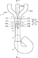
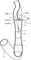
- FIG. 3 is a sectional view taken along line III-III of the exhaust device shown in FIG. 2. It is a side view of the exhaust apparatus shown in FIG.
- FIG. 5 is a cross-sectional view of the exhaust device shown in FIG. 2 taken along line VV.
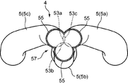
- FIG. 6 is a cross-sectional view of the exhaust device shown in FIG. 2 taken along line VI-VI.
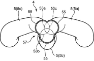
- FIG. 3 is a cross-sectional view of the exhaust device shown in FIG. 2 taken along the line VII-VII.
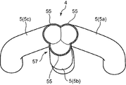
- FIG. 5 is a cross-sectional view of the exhaust device shown in FIG. 2 taken along line VIII-VIII.
- FIG. 14 is a cross-sectional view of the exhaust device shown in FIG. 13 taken along the line XIV-XIV.
- FIG. 15 is a side view of the exhaust apparatus shown in FIG.
- FIG. 15 is a cross-sectional view of the exhaust device shown in FIG. 14 taken along line XVI-XVI.
- FIG. 15 is a cross-sectional view of the exhaust device shown in FIG. 14 taken along line XVII-XVII.
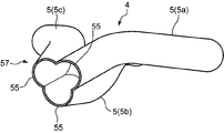
- FIG. 15 is a cross-sectional view of the exhaust device shown in FIG. 14 taken along line XVIII-XVIII. It is sectional drawing which looked at the exhaust apparatus shown in FIG. 16 from the diagonal direction.
- FIG. 20 is a cross-sectional view of the exhaust device shown in FIG. 16 when viewed from an oblique direction different from FIG. 19. It is sectional drawing which looked at the exhaust apparatus shown in FIG. 16 from the diagonal direction different from FIG.
- FIG. 23 is a cross-sectional view of the exhaust device shown in FIG. 22 taken along line XXIII-XXIII. It is a side view of the exhaust apparatus of the engine shown in FIG.
- FIG. 24 is a sectional view of the exhaust device shown in FIG. 23 taken along the line XXV-XXV.
- FIG. 23 is a cross-sectional view of the exhaust device shown in FIG. 22 taken along line XXVI-XXVI.
- FIG. 23 is a cross-sectional view of the exhaust device shown in FIG. 22 taken along line XXVII-XXVII.
- the engine includes an engine body 1 having a cylinder head 3 and a cylinder block (not shown), a plurality of intake pipes 2 connected to the engine body 1, an exhaust manifold 4 connected to the engine body 1, and an exhaust manifold 4 And a downstream exhaust pipe 8 connected to the ECU 8 and an ECU 9 for engine control.
- the exhaust manifold 4 corresponds to the exhaust device of the present invention.
- a plurality of cylinders 12 each having a piston fitted therein are formed in the cylinder head 3 and the cylinder block.
- the engine (engine body 1) is an in-line four-cylinder engine, and four cylinders 12 are formed in series in the cylinder head 3 and the cylinder block. Specifically, a first cylinder 12a, a second cylinder 12b, a third cylinder 12c, and a fourth cylinder 12d are formed in order from the left in FIG. 12 ”).
- Each cylinder head 3 is provided with an ignition plug so as to face a combustion chamber defined above the piston.
- the engine body 1 is a four-cycle engine, and as shown in FIG. 9, each cylinder 12a to 12d is configured to be ignited by the spark plug at a timing shifted by 180 ° CA. That is, the intake stroke, the compression stroke, the expansion stroke, and the exhaust stroke are each shifted by 180 ° CA. In the present embodiment, ignition is performed in the order of the first cylinder 12a ⁇ the third cylinder 12c ⁇ the fourth cylinder 12d ⁇ the second cylinder 12b.
- each intake port 17 and two exhaust ports 18 each opening toward the combustion chamber.
- the intake port 17 is for introducing intake air into each cylinder 12.
- the exhaust port 18 is for exhausting the exhaust from each cylinder 12.
- Each intake port 17 is provided with an intake valve 19 for opening and closing the intake port 17 to communicate or block the intake port 17 and the inside of the cylinder 12.
- Each exhaust port 18 is provided with an exhaust valve 20 for opening and closing the exhaust port 18 to communicate or block the exhaust port 18 and the inside of the cylinder 12.
- the intake valve 19 is driven by an intake valve drive mechanism 30 to open and close the intake port 17 at a predetermined timing.
- the exhaust valve 20 is driven by an exhaust valve drive mechanism 40 to open and close the exhaust port 18 at a predetermined timing.
- the intake valve drive mechanism 30 has an intake camshaft 31 that is in contact with the intake valve 19 and an intake side variable valve timing mechanism 10.
- the intake camshaft 31 is connected to the crankshaft via a known power transmission mechanism such as a chain / sprocket mechanism, and rotates with the rotation of the crankshaft to drive the intake valve 19 to open and close.
- the intake side variable valve timing mechanism 10 is for changing the valve timing of the intake valve 19.
- the intake-side variable valve timing mechanism 10 changes the phase difference between a predetermined driven shaft that is arranged coaxially with the intake camshaft 31 and is directly driven by the crankshaft, and the intake camshaft 31, thereby By changing the phase difference between the crankshaft and the intake camshaft 31, the valve timing of the intake valve 19 is changed.
- the intake side variable valve timing mechanism 10 changes the phase difference based on the target valve timing of the intake valve 19 calculated by the ECU 2.
- the exhaust valve drive mechanism 40 has the same structure as the intake valve drive mechanism 30. That is, the exhaust valve driving mechanism 40 is in contact with the exhaust valve 20 and changes the phase difference between the exhaust camshaft 41 connected to the crankshaft and the exhaust camshaft 41 and the crankshaft. 20 has an exhaust side variable valve timing mechanism 11 for changing the valve timing.
- the exhaust side variable valve timing mechanism 11 changes the phase difference based on the target valve timing of the exhaust valve 20 calculated by the ECU 9.
- the exhaust camshaft 41 rotates with the rotation of the crankshaft under this phase difference, and opens and closes the exhaust valve 20 at the target valve timing.
- the target valve timings of the intake valve 19 and the exhaust valve 20 are the exhaust of each cylinder 12 in a predetermined operation region (for example, the entire operation region, a partial region such as a predetermined reference rotational speed or less, a low speed / high load region, etc.).
- the opening period of the valve 20 and the opening period of the intake valve 19 overlap with each other across the intake top dead center (TDC), and one cylinder (leads) between the cylinders 12 and 12 in which the exhaust order is continuous.
- the exhaust valve 20 of the other cylinder (following cylinder) 12 is set to start opening during the overlap period T_O / L of the cylinder) 12. More specifically, as shown in FIG.
- the exhaust valve 20 of the third cylinder 12c is opened during the period in which the exhaust valve 20 and the intake valve 19 of the first cylinder 12a overlap, While the exhaust valve 20 and the intake valve 19 of the cylinder 12c overlap, the exhaust valve 20 of the fourth cylinder 12d opens, and the exhaust valve 20 and the intake valve 19 of the fourth cylinder 12d overlap.
- the exhaust valve 20 of the second cylinder 12b opens during the period during which the exhaust valve 20 of the second cylinder 12b overlaps the intake valve 19 and the exhaust valve 20 of the second cylinder 12b opens.
- the target valve timing is set so as to valve.
- the intake ports 17 of the cylinders 12a to 12d are connected to the intake pipe 2 on the upstream side. Specifically, four intake pipes 2 are provided corresponding to the number of cylinders, and two intake ports 17 provided in each cylinder 12 are connected to one intake pipe 2.
- the exhaust manifold 4 includes, in order from the upstream side, three independent exhaust pipes 5 and a mixing pipe 50 connected to the downstream end of each independent exhaust pipe 5 and into which exhaust gas that has passed through each independent exhaust pipe 5 flows.
- the mixing tube 50 includes, on its axis, a straight portion 6 (corresponding to the “aggregation portion” of the present invention) extending in order from the upstream side to the downstream side, and a diffuser portion 7 having a flow path area that increases toward the downstream side. It has. That is, the downstream end of each independent exhaust pipe 5 is connected to the upstream end of the straight portion 6.
- each independent exhaust pipe 5 is connected to the exhaust port 18 of each cylinder 12a to 12d.
- the exhaust port 18 of the first cylinder 12a and the exhaust port 18 of the fourth cylinder 12d are individually connected to one independent exhaust pipe 5a, 5c, respectively.
- the exhaust port 18 of the second cylinder 12b and the exhaust port 18 of the third cylinder 12c in which the exhaust strokes are not adjacent to each other and the exhaust order is not continuous, are not exhausted simultaneously from these cylinders. From the viewpoint of simplification, it is connected to one common independent exhaust pipe 5b.
- the independent exhaust pipe 5b connected to the exhaust port 18 of the second cylinder 12b and the exhaust port 18 of the third cylinder 12c branches into two passages on the upstream side thereof,
- the exhaust port 18 of the second cylinder 12b is connected to the other, and the exhaust port 18 of the third cylinder 12c is connected to the other.
- the independent exhaust pipe 5b corresponding to the second cylinder 12b and the third cylinder 12c faces between the cylinders 12b and 12c, that is, the substantially central portion of the engine body 1. It extends linearly toward the mixing tube 50 at a position where it does.
- the independent exhaust pipes 5a and 5c respectively corresponding to the first cylinder 12a and the fourth cylinder 12d extend toward the mixing pipe 50 while curving from positions facing the cylinders 12a and 12d.
- independent exhaust pipe 5 (hereinafter simply referred to as “independent exhaust pipe 5” if they do not need to be distinguished from each other) are independent of each other, and are the second cylinder 12b or the third cylinder.
- the exhaust discharged from 12c, the exhaust discharged from the first cylinder 12a, and the exhaust discharged from the fourth cylinder 12d are independent of each other and pass through the respective independent exhaust pipes 5a, 5b, and 5c.
- Exhaust gas that has passed through the independent exhaust pipes 5 a, 5 b, 5 c flows into the straight portion 6 of the mixing pipe 50.
- Each of the independent exhaust pipes 5 and the straight portions 6 are mixed around the high-speed exhaust gas as the exhaust gas is ejected from each independent exhaust pipe 5 at a high speed and the exhaust gas flows into the straight part 6 at a high speed.
- a negative pressure in the pipe 50 that is, a negative pressure is generated in the adjacent independent exhaust pipe 5 and the exhaust port 18 communicating with the independent exhaust pipe 5 by the ejector effect, and the exhaust in the exhaust port 18 is downstream. It has a shape that can be sucked out.
- each independent exhaust pipe 5 has its channel area (the channel with respect to the exhaust flow direction as it goes downstream, so that exhaust gas is ejected from each independent exhaust pipe 5 into the straight part 6 at high speed. It has a shape in which the flow path area when cut by the orthogonal plane is small.
- a cross section of the internal space that is, a cross section of the exhaust passage (a cross section when cut along a plane orthogonal to the exhaust flow direction).
- the independent exhaust pipes 5a, 5b, and 5c are formed in an internal space having a circular cross section of the independent exhaust pipe 5a in a predetermined section K1 (see FIG. 2) from the downstream end to the upstream side.
- 53a, a part of the internal space 53b having a circular cross section of the independent exhaust pipe 5b, and a part of the internal space 53c having a circular cross section of the independent exhaust pipe 5c overlap each other, and the overlapping ratio is the above-mentioned interval It is connected to the upstream end of the straight portion 6 so as to gradually increase from the upstream side toward the downstream side at K1.
- the “internal space” as used herein means a space surrounded by the inner peripheral surface of the independent exhaust pipe 5 in a region where the pipe wall of the independent exhaust pipe 5 exists over the entire circumferential direction.
- the pipe wall is virtually extended circularly in the entire circumferential direction (FIG. 6, FIG. 7) (refer to a two-dot chain line circle in FIG. 7) means a space surrounded by the entire inner peripheral surface of the tube wall.
- the internal space 53a of the independent exhaust pipe 5a, the internal space 53b of the independent exhaust pipe 5b, and the independent exhaust pipe 5c slightly overlaps with each other.
- internal spaces 53a, 53b, and 53c shown in FIG. 6 indicate internal spaces in the vicinity of the section taken along the line VI-VI in FIG.
- the overlapping area of the internal space 53a, the internal space 53b, and the internal space 53c is larger than the overlapping area shown in FIG.
- internal spaces 53a, 53b, and 53c shown in FIG. 7 indicate internal spaces in the vicinity of the section taken along line VII-VII in FIG.
- each independent exhaust pipe 5 has its axis in a section K1 (hereinafter referred to as “overlap section K1”) in which a part of the internal space overlaps each other. It has a downstream end face 51 that is inclined with respect to L1.
- the downstream end face 51 has a shape in which a part of the tube wall is cut out at an angle inclined with respect to the axis L1 (for example, an angle that forms an acute angle with the axis L1).
- the overlapping section K1 has an upstream overlapping section K11 on the upstream side in the exhaust flow direction and a downstream overlapping section K12 adjacent to the downstream side of the upstream overlapping section K11.
- each downstream end face 51 of the independent exhaust pipes 5a, 5b, and 5c protrudes toward the downstream side when viewed from the outer peripheral surface side of the pipe wall. While being substantially U-shaped, the end portions of each other are continuous, and the intermediate portions thereof are arranged facing each other in a spaced state.
- the straight portion 6 is provided between the independent exhaust pipe 5a and the independent exhaust pipe 5b, between the independent exhaust pipe 5b and the independent exhaust pipe 5c, and independently in the downstream overlapping section K12.
- a part (three places) in the circumferential direction protrudes upstream so as to fill three gaps between the exhaust pipe 5a and the independent exhaust pipe 5c.
- the upstream end surface 61 of the protrusion part 62 is joined to the downstream end surface 51 of the independent exhaust pipes 5a, 5b, 5c.
- the exhaust gas flowing into the straight portion 6 from each independent exhaust pipe 5 is merged in the straight portion 6, and the merged exhaust gas is sequentially transferred from the straight portion 6 to the diffuser portion 7 and the downstream exhaust pipe 8. It flows.
- a part of the internal space 53a having a circular cross section of the independent exhaust pipe 5a, a part of the internal space 53b having a circular cross section of the independent exhaust pipe 5b, and a circular cross section of the independent exhaust pipe 5c are provided.
- Each of the independent exhaust pipes 5a to 5c is connected to the upstream end of the straight portion 6 so that a part of the internal space 53c overlaps with each other and the overlapping ratio gradually increases from the upstream side toward the downstream side. ing.
- the exhaust gas discharged from each independent exhaust pipe 5 flows into the straight portion 6 while maintaining its circulation shape in a substantially circular shape, whereby the exhaust gas flowing from each independent exhaust pipe 5 becomes a straight section having a circular cross section.
- the back flow of the exhaust gas from the downstream side in the straight portion 6 is suppressed as compared with the conventional technique.
- FIG. 10 shows an example of the exhaust gas flow velocity distribution in the straight portion 6 of the exhaust device of the present embodiment.
- FIG. 11 shows the exhaust gas flow rate in the straight portion of the conventional exhaust device described in Patent Document 1.
- An example of the flow velocity distribution is shown.
- the area of the portion where the flow velocity is large in the exhaust gas flowing in the downstream side (the portion other than the backflow portion in FIG. 10) in the internal space of the straight portion 6.
- the area of the backflow portion of the exhaust gas from the downstream side is relatively small.
- the exhaust gas flowing downstream has a relatively small area of the portion where the flow velocity is large, and is from the downstream side.
- the area of the backflow portion of the exhaust gas is relatively large.
- the exhaust gas suction amount due to the ejector effect is larger in the exhaust device of the present embodiment than in the conventional exhaust device.
- the independent exhaust pipes 5a, 5b, and 5c have a predetermined section K2 from the downstream end to the upstream side (see FIG. 13; hereinafter referred to as “overlapping section K2”).
- overlapping section K2 A part of the internal space 53a having a circular cross section of the independent exhaust pipe 5a, a part of the internal space 53b having a circular cross section of the independent exhaust pipe 5b, and a part of the internal space 53c having a circular cross section of the independent exhaust pipe 5c are connected to the upstream end of the straight portion 6 so that the overlapping ratio gradually increases from the upstream side toward the downstream side in the overlapping section K2.
- the axis L1 in the downstream portion of each independent exhaust pipe 5 intersects with each other at one point P on the axis L2 of the straight portion 6 as shown in FIG.
- the internal space 53a, the internal space 53b, and the internal space 53c slightly overlap each other.
- internal spaces 53a, 53b, and 53c shown in FIG. 16 indicate internal spaces in the vicinity of the XVI-XVI line cross section of FIG.
- the overlapping area of the internal space 53a, the internal space 53b, and the internal space 53c is larger than the overlapping area shown in FIG.
- each of the independent exhaust pipes 5a, 5b, and 5c has an arcuate tube wall 55 in the overlapping section K2 when viewed from the direction of the axis L1.
- the circumferential direction edge part of each pipe wall 55 of the independent exhaust pipe 5a, 5b, 5c is mutually joined, and the variant which has a some bulging part (namely, arcuate pipe wall 55) seeing from the axial center L1 direction.
- a peripheral wall 57 is formed.
- the deformed peripheral wall 57 has a cross section in a direction orthogonal to the axial direction gradually approaching a circular shape from the upstream side toward the downstream side, and becomes a circular shape having the same diameter as the upstream end of the straight portion 6 at the downstream end.
- the straight portion 6 is connected to the upstream end.
- the peripheral wall 55 of the independent exhaust pipes 5a, 5b, 5c has a gradually increasing diameter in the overlapping section K2 (see the two-dot chain line circles in FIGS. 16 to 18). As shown in FIGS. 16 to 18, the angle formed by the tangents to the outer peripheral surface of the peripheral wall 55 at the joint portion of the peripheral walls 55 gradually decreases toward the downstream side.
- the straight portion 6 of the present embodiment has a structure in which the protruding portion 62 in the first embodiment is removed, and its upper end surface is circular.
- the exhaust discharged from each independent exhaust pipe 5 flows into the straight portion 6 while maintaining its circulation shape in a substantially circular shape.
- the exhaust gas flowing in from 5 is distributed substantially uniformly throughout the straight section 6 having a circular cross section.
- the backflow of the exhaust from the downstream side in the straight portion 6 is suppressed as compared with the conventional exhaust device.
- the amount of exhaust sucked from the independent exhaust pipe 5 can be increased, and the engine output can be effectively improved.
- the mixing tube 50 includes the truncated cone portion 13, the straight portion 6, and the diffuser portion 7 in order from the upstream side on the axial center.
- the frustoconical portion 13 extends downstream and has a smaller flow area on the downstream side, and the diffuser portion 7 has a larger flow area on the downstream side.
- the truncated cone portion 13 has a disc-shaped end wall portion 14 (see FIG. 23) at the upstream end portion thereof.
- the downstream end of each independent exhaust pipe 5 is connected to the opening 16 formed in the end wall 14.
- the opening 16 has a shape in which the ends of three arcs arranged in the circumferential direction around the center of the end wall portion 14 are connected to each other.
- the axis L1 in the downstream portion of each independent exhaust pipe 5 intersects with each other at one point P on the axis L3 of the truncated cone portion 13 as shown in FIG.
- the independent exhaust pipes 5a, 5b, 5c are cross sections of the independent exhaust pipe 5a in a predetermined section K3 from the downstream end to the upstream side (see FIG. 22, hereinafter referred to as “overlap section K3”).
- overlap section K3 A part of the circular internal space 53a, a part of the internal space 53b having a circular cross section of the independent exhaust pipe 5b, and a part of the internal space 53c having a circular cross section of the independent exhaust pipe 5c overlap with each other. It is connected to the upstream end of the truncated cone portion 13 so that the ratio gradually increases from the upstream side toward the downstream side in the overlapping section K3.
- each downstream end face 51 of the independent exhaust pipes 5a, 5b, 5c is cut out by a plane inclined with respect to the axis L1.
- a portion 51 a formed and joined to each other and a portion 51 b joined to the truncated cone portion 13 are included.
- the exhaust discharged from each independent exhaust pipe 5 flows and is mixed into the frustoconical portion 13 while maintaining the flow shape thereof in a substantially circular shape, and the mixed exhaust gas has its flow shape. Is maintained in a substantially circular shape and flows into the straight portion 6 having a circular cross section, and is distributed substantially uniformly throughout the straight portion 6. As a result, the backflow of the exhaust from the downstream side in the straight portion 6 is suppressed as compared with the conventional exhaust device. Thereby, the amount of exhaust sucked from the independent exhaust pipe 5 can be increased, and the engine output can be effectively improved.
- the above embodiments are applied to a four-cylinder engine.
- the present invention is not limited to this, and can be applied to a six-cylinder engine, an eight-cylinder engine, and the like.
- the present invention relates to an exhaust device connected to the engine body of an engine having an engine body having a plurality of cylinders, wherein the exhaust ports of each cylinder of the engine body or the exhaust ports of a plurality of cylinders in which the exhaust order is not continuous
- a plurality of independent exhaust pipes each having a circular cross section connected to each other, and a mixing pipe having a circular cross section connected to the downstream end of each independent exhaust pipe and into which exhaust gas having passed through each independent exhaust pipe flows.
- the independent exhaust pipe a part of the circular inner space overlaps each other in a predetermined section from the downstream end to the upstream side, and the overlapping ratio gradually increases from the upstream side toward the downstream side. And connected to the upstream end of the mixing tube.
- the exhaust discharged from each independent exhaust pipe flows into the mixing pipe while maintaining its circulation shape in a substantially circular shape, the exhaust flowing from each independent exhaust pipe is distributed throughout the mixing pipe having a circular cross section. It will be distributed substantially uniformly. As a result, the backflow of the exhaust gas from the downstream side is suppressed, the exhaust amount of the exhaust gas from the independent exhaust pipe is increased, and the engine output can be improved.
- the mixing pipe has a collecting portion where exhaust gases flowing in from the independent exhaust pipes gather, and the collecting portion has the same inner diameter in the entire axial direction.
- the exhaust gas flowing in from each independent exhaust pipe can be more evenly distributed in the mixing pipe, and the back flow of the exhaust gas from the downstream side can be further reduced. Can be suppressed.
- each of the independent exhaust pipes has a downstream end face that is inclined with respect to the axial center in a section in which a part of the internal space overlaps with each other, and the downstream exhaust face faces each other.
- the upstream end of the mixing pipe has a shape in which a part of the circumferential direction protrudes upstream so as to fill a gap between the downstream end faces facing each other, and the downstream end face of each independent exhaust pipe And the upstream end of the mixing tube are preferably joined to each other.
- downstream end of the independent exhaust pipe and the upstream end of the collecting portion can be made relatively simple, and can be manufactured relatively easily.
- Each of the independent exhaust pipes has an arcuate tube wall as viewed from the axial direction in a section where a part of the internal space overlaps each other, and a circumferential end portion of the pipe wall is They are joined together to form a deformed peripheral wall having a plurality of bulged portions when viewed from the mixing tube side, and the deformed peripheral wall has a cross section in a direction orthogonal to the axial direction from the upstream side toward the downstream side. It is preferable that the shape gradually approaches a circle, becomes a circle having the same diameter as the upstream end of the mixing tube at the downstream end, and is connected to the upstream end of the mixing tube.
- the exhaust gas can smoothly flow from the independent exhaust pipe to the mixing pipe.
Landscapes
- Engineering & Computer Science (AREA)
- Chemical & Material Sciences (AREA)
- Combustion & Propulsion (AREA)
- Mechanical Engineering (AREA)
- General Engineering & Computer Science (AREA)
- Exhaust Silencers (AREA)
- Characterised By The Charging Evacuation (AREA)
Abstract
エンジン本体(1)に接続された排気装置(4)。排気装置(4)は、エンジン本体(1)の各気筒の排気ポート(12)に接続される断面円形の複数の独立排気管(5)と、各独立排気管(5)の下流端に接続されて各独立排気管(5)を通過した排気が流入する断面円形の混合管(50)とを備える。各独立排気管(5)は、その下流端から上流側への所定の区間(K1)でその断面円形の内部空間の一部が互いに重複するとともに、その重複する割合が上流側から下流側に向かって徐々に増加するように、混合管(50)の上流端に接続されている。
Description
本発明は、多気筒エンジンの排気装置に関する。
従来、自動車等のエンジンにおいて、エンジン出力を高めることを目的とした排気装置の開発が行なわれている。そのような排気装置の一例が特許文献1に開示されている。特許文献1に記載の排気装置は、排気順序が連続しない複数の気筒の排気ポートにそれぞれ接続される複数の独立排気管と、各独立排気管の下流端に接続されて各独立排気管を通過した排気が流入する断面円形の混合管とを備え、各独立排気管の下流端の断面形状が互いに同じ扇形に形成され、各扇形が集合して円が形成されるように各独立排気管が束ねられた状態で各独立排気管の下流端が混合管の上流端に接続された構造となっている。
この排気装置によれば、各独立排気管を通過した排気が混合管に流入することにより混合管内に負圧が発生し、この負圧により、他の独立排気管およびこれと連通する他の気筒の排気ポート内の排気が下流側に吸い出されるエゼクタ効果が得られる。そして、このエゼクタ効果により、上記他の気筒からの排気が促進され、エンジンの出力が高められる。
しかしながら、特許文献1に記載の排気装置においては、独立排気管における断面扇形の下流端から断面円形の混合管に排気が流入するようになっているため、独立排気管から流入した排気が混合管内に均等に分布し難く、その結果、混合管内に排気の逆流が生じ易くなり、独立排気管からの排気の吸出し量が十分に確保されない虞があった。
本発明は、上記の事情に鑑みて成されたものであり、エゼクタ効果を利用してエンジン出力の向上を図るエンジンの排気装置において、独立排気管からの排気の吸出し量の増大を図ることができるエンジンの排気装置を提供することを目的とする。
そして、本発明は、複数の気筒を備えたエンジン本体を有するエンジンの前記エンジン本体に接続された排気装置であって、前記エンジン本体の各気筒の排気ポートまたは排気順序が連続しない複数の気筒の排気ポートにそれぞれ接続される断面円形の複数の独立排気管と、前記各独立排気管の下流端に接続されて各独立排気管を通過した排気が流入する断面円形の混合管と、を備え、前記各独立排気管は、その下流端から上流側への所定の区間でその断面円形の内部空間の一部が互いに重複するとともに、その重複する割合が上流側から下流側に向かって徐々に増加するように、前記混合管の上流端に接続されているものである。
以下、添付図面を参照しながら本発明の好ましい実施形態について詳述する。
(第1実施形態)
本発明は、図1に示すエンジンに適用されている。
本発明は、図1に示すエンジンに適用されている。
このエンジンは、シリンダヘッド3およびシリンダブロック(図示略)を有するエンジン本体1と、エンジン本体1に接続される複数の吸気管2と、エンジン本体1に接続される排気マニホールド4と、排気マニホールド4に接続される下流側排気管8と、エンジン制御用のECU9とを備えている。なお、当実施形態では、前記排気マニホールド4が本発明の排気装置に相当する。
前記シリンダヘッド3及びシリンダブロックの内部にはピストンがそれぞれ嵌挿された複数の気筒12が形成されている。本実施形態に係るエンジン(エンジン本体1)は、直列4気筒エンジンであって、前記シリンダヘッド3及びシリンダブロックの内部には4つの気筒12が直列に並んだ状態で形成されている。具体的には、図1の左から順に第1気筒12a,第2気筒12b,第3気筒12c,第4気筒12dが形成されている(以下、特に区別する必要がない場合には単に「気筒12」と称する場合がある)。前記シリンダヘッド3には、ピストンの上方に区画された燃焼室内に臨むようにそれぞれ点火プラグが設置されている。
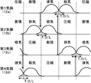
エンジン本体1は4サイクルエンジンであって、図9に示すように、各気筒12a~12dにおいて、180°CAずつずれたタイミングで前記点火プラグによる点火が行われるように構成されている。つまり、吸気行程、圧縮行程、膨張行程、排気行程がそれぞれ180°CAずつずれるように構成されている。本実施形態では、第1気筒12a→第3気筒12c→第4気筒12d→第2気筒12bの順に点火が行われる。
各気筒12a~12dの上部には、それぞれ燃焼室に向かって開口する2つの吸気ポート17及び2つの排気ポート18が設けられている。吸気ポート17は、各気筒12内に吸気を導入するためのものである。排気ポート18は、各気筒12内から排気を排出するためのものである。各吸気ポート17には、これら吸気ポート17を開閉して吸気ポート17と気筒12内部とを連通又は遮断するための吸気バルブ19が設けられている。各排気ポート18には、これら排気ポート18を開閉して排気ポート18と気筒12内部とを連通又は遮断するための排気バルブ20が設けられている。前記吸気バルブ19は吸気バルブ駆動機構30により駆動されることで、所定のタイミングで吸気ポート17を開閉する。また、前記排気バルブ20は、排気バルブ駆動機構40により駆動されることで、所定のタイミングで排気ポート18を開閉する。
吸気バルブ駆動機構30は、吸気バルブ19に当接された吸気カムシャフト31と吸気側可変バルブタイミング機構10とを有している。吸気カムシャフト31は、周知のチェーン・スプロケット機構等の動力伝達機構を介してクランクシャフトに連結されており、クランクシャフトの回転に伴い回転して、吸気バルブ19を開閉駆動する。
吸気側可変バルブタイミング機構10は、吸気バルブ19のバルブタイミングを変更するためのものである。この吸気側可変バルブタイミング機構10は、吸気カムシャフト31と同軸に配置されてクランクシャフトにより直接駆動される所定の被駆動軸と吸気カムシャフト31との間の位相差を変更して、これによりクランクシャフトと前記吸気カムシャフト31との間の位相差を変更することで、吸気バルブ19のバルブタイミングを変更する。この吸気側可変バルブタイミング機構10は、ECU2で算出された吸気バルブ19の目標バルブタイミングに基づいて前記位相差を変更する。
排気バルブ駆動機構40は、吸気バルブ駆動機構30と同様の構造を有している。すなわち、排気バルブ駆動機構40は、排気バルブ20に当接され、クランクシャフトに連結された排気カムシャフト41と、この排気カムシャフト41とクランクシャフトとの間の位相差を変更することで排気バルブ20のバルブタイミングを変更する排気側可変バルブタイミング機構11とを有している。排気側可変バルブタイミング機構11は、ECU9で算出された排気バルブ20の目標バルブタイミングに基づいて前記位相差を変更する。そして、排気カムシャフト41は、この位相差の下でクランクシャフトの回転に伴い回転して、排気バルブ20を前記目標バルブタイミングで開閉駆動する。
ここで、吸気バルブ19及び排気バルブ20の目標バルブタイミングについて説明する。
吸気バルブ19及び排気バルブ20の目標バルブタイミングは、所定の運転領域(例えば全運転領域又は所定の基準回転数以下等の一部の領域、低速・高負荷域等)において、各気筒12の排気バルブ20の開弁期間と吸気バルブ19の開弁期間とが吸気上死点(TDC)を挟んでオーバーラップし、かつ、排気順序が連続する気筒12,12間において、一方の気筒(先行する気筒)12のオーバーラップ期間T_O/L中に、他方の気筒(後続の気筒)12の排気バルブ20が開弁を開始するように設定されている。より具体的には、図9に示すように、第1気筒12aの排気バルブ20と吸気バルブ19とがオーバーラップしている期間中に第3気筒12cの排気バルブ20が開弁し、第3気筒12cの排気バルブ20と吸気バルブ19とがオーバーラップしている期間中に第4気筒12dの排気バルブ20が開弁し、第4気筒12dの排気バルブ20と吸気バルブ19とがオーバーラップしている期間中に第2気筒12bの排気バルブ20が開弁し、第2気筒12bの排気バルブ20と吸気バルブ19とがオーバーラップしている期間中に第1気筒12aの排気バルブ20が開弁するように目標バルブタイミングが設定されている。
各気筒12a~12dの吸気ポート17は、その上流側においてそれぞれ吸気管2に接続されている。具体的には、吸気管2は気筒数に対応して4本設けられており、各気筒12に設けられた2つの吸気ポート17が、1つの吸気管2に接続されている。
排気マニホールド4は、上流側から順に、3つの独立排気管5と、各独立排気管5の下流端に接続されて各独立排気管5を通過した排気が流入する混合管50とを有する。混合管50は、その軸心上に、上流側から順に、下流側に延びるストレート部6(本発明の「集合部」に相当する)と、下流側ほど流路面積が大きくなるディフューザー部7とを備えている。つまり、各独立排気管5の下流側端部は、ストレート部6の上流側端部に接続されている。
各独立排気管5の上流側端部は、各気筒12a~12dの排気ポート18に接続されている。具体的には、第1気筒12aの排気ポート18及び第4気筒12dの排気ポート18は、それぞれ個別に1つの独立排気管5a、5cに接続されている。一方、排気行程が隣り合わず排気順序が連続しない第2気筒12bの排気ポート18と第3気筒12cの排気ポート18とは、これら各気筒から同時に排気が排出されることがないため、構造を簡素化する観点から、共通の1つの独立排気管5bに接続されている。より詳細には、この第2気筒12bの排気ポート18と第3気筒12cの排気ポート18とに接続されている独立排気管5bは、その上流側において2つの通路に分岐しており、その一方に前記第2気筒12bの排気ポート18が接続され、他方に前記第3気筒12cの排気ポート18が接続されている。
本実施形態では、図1にも示すように、第2気筒12bと前記第3気筒12cとに対応する独立排気管5bは、これら気筒12b,12cの間すなわちエンジン本体1の略中央部分と対向する位置において混合管50に向かって直線的に延びている。第1気筒12a及び第4気筒12dにそれぞれ対応する独立排気管5a、5cは、各気筒12a、12dと対向する位置から湾曲しつつ前記混合管50に向かって延びている。
これら独立排気管5a、5b、5c(以下、特に区別する必要がない場合には単に「独立排気管5」と称する場合がある)は、互いに独立しており、第2気筒12bまたは第3気筒12cから排出された排気と、第1気筒12aから排出された排気と、第4気筒12dから排出された排気とは、互いに独立して各独立排気管5a、5b、5c内を通って下流側に排出される。各独立排気管5a、5b、5cを通過した排気は混合管50のストレート部6に流入する。
各独立排気管5及びストレート部6は、各独立排気管5から高速で排気が噴出されてこの排気が高速でストレート部6内に流入するのに伴い、この高速の排気の周囲に発生した混合管50内の負圧作用、すなわちエゼクタ効果によって隣接する他の独立排気管5及びこの独立排気管5と連通する排気ポート18内に負圧が生成され、この排気ポート18内の排気が下流側に吸い出されるような形状を有している。
そして、各独立排気管5の下流部は、排気が各独立排気管5から高速でストレート部6内に噴出されるよう、下流に向かうほどその流路面積(流路を排気流れ方向に対して直交する面で切断したときの流路面積)が小さくなる形状を有している。本実施形態では、図5に示すように、各独立排気管5の下流部では、その内部空間の断面、すなわち排気通路の断面(排気流れ方向に対して直交する面で切断したときの断面)が略円形をなしており、その上流側部分から下流側に向かうに従ってその断面積が次第に縮小されており、その下流端では上流端の断面積の略1/3の断面積(流路面積)となっている。
そして、図6~8に示すように、独立排気管5a,5b,5cは、その下流端から上流側への所定の区間K1(図2参照)において、独立排気管5aの断面円形の内部空間53aの一部と、独立排気管5bの断面円形の内部空間53bの一部と、独立排気管5cの断面円形の内部空間53cの一部とが互いに重複するとともに、その重複する割合が上記区間K1において上流側から下流側に向かって徐々に増加するように、ストレート部6の上流端に接続されている。
なお、ここで言う「内部空間」とは、独立排気管5の管壁が周方向全体に亘って存在している領域では、独立排気管5の内周面で囲まれる空間を意味し、独立排気管5の管壁が周方向の一部にのみ存在している領域、すなわち、図2における区間K1では、管壁を周方向全体に円形状に仮想的に延長した場合(図6、図7の二点鎖線円参照)にその管壁の内周面全体で囲まれる空間を意味する。
内部空間を上記のように定義した場合に、本実施形態では、図6に示されるように、独立排気管5aの内部空間53aと、独立排気管5bの内部空間53bと、独立排気管5cの内部空間53cとが互いに僅かに重複している。ここで、図6に示される内部空間53a,53b,53cは、図2のVI-VI線断面付近の内部空間を示している。そして、より下流側では、図7に示されるように、内部空間53aと、内部空間53bと、内部空間53cとの重複面積が、図6に示される重複面積よりも大きくなっている。ここで、図7に示される内部空間53a,53b,53cは、図2のVII-VII線断面付近の内部空間を示している。
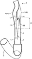
より具体的には、図2~4に示されるように、各独立排気管5は、内部空間の一部が互いに重複する区間K1(以下、「重複区間K1」と称する)において、その軸心L1に対して傾斜した下流側端面51を有する。この下流側端面51は、管壁の一部が軸心L1に対して傾斜した角度(例えば軸心L1と鋭角を成す角度)で切り欠かれた形状を有している。本実施形態では、各独立排気管5の下流部の軸心L1は、図3に示されるように、ストレート部6の軸心L2上において1つの点Pで互いに交わっている。さらに、本実施形態では、重複区間K1は排気流れ方向上流側の上流側重複区間K11と、当該上流側重複区間K11の下流側に隣接する下流側重複区間K12とを有する。
上流側重複区間K11では、図2、3に示されるように、独立排気管5a,5b,5cの各下流側端面51は、その軸心L1に対して傾斜した方向に延びるとともに互いに接合されている。下流側重複区間K12では、図2、3に示されるように、独立排気管5a,5b,5cの各下流側端面51は、管壁の外周面側から見て、下流側に向かって突出する略U字状をなすとともに、互いの端部同士が連続し、互いの中間部分同士が離間した状態で向かい合うように配置されている。このような構成とされることにより、下流側重複区間K12において、独立排気管5a,5b,5cの各下流側端面51は、その全体で、管壁の外周面側から見て波状を呈するように形成されている。
ストレート部6は、下流側重複区間K12において、図2~4に示されるように、独立排気管5aと独立排気管5bとの間、独立排気管5bと独立排気管5cとの間、および独立排気管5aと独立排気管5cとの間の3箇所の隙間を埋めるように周方向の一部(3箇所)が上流側に突出する形状を有している。そして、その突出部分62の上流側端面61が、独立排気管5a,5b,5cの下流側端面51に接合されている。
次に、本実施形態の作用効果について説明する。
本実施形態では、各独立排気管5からストレート部6に流入した排気ガスが、ストレート部6内で合流し、その合流した排気ガスがストレート部6からディフューザー部7、下流側排気管8へ順次流れていく。
本実施形態では、上述のように、独立排気管5aの断面円形の内部空間53aの一部と、独立排気管5bの断面円形の内部空間53bの一部と、独立排気管5cの断面円形の内部空間53cの一部とが互いに重複するとともに、その重複する割合が上流側から下流側に向かって徐々に増加するように、各独立排気管5a~5cがストレート部6の上流端に接続されている。このため、各独立排気管5から排出された排気が、その流通形状を略円形に維持したままストレート部6に流入し、これにより、各独立排気管5から流入した排気が円形断面のストレート部6内全体に略均一に分布することになり、その結果、ストレート部6における下流側からの排気の逆流が上記従来技術に比べて抑制される。
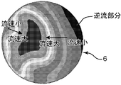
図10は、本実施形態の排気装置の上記ストレート部6における排気ガスの流速分布の一例を示しており、図11は、特許文献1に記載された従来の排気装置のストレート部における排気ガスの流速分布の一例を示している。図10に示されるように、本実施形態の排気装置では、ストレート部6の内部空間において、下流側に流れる排気ガス(図10中の逆流部分以外の部分)のうち、流速の大きい部分の面積が相対的に大きく、下流側からの排気ガスの逆流部分の面積が相対的に小さくなっている。これに対し、図11に示されるように、従来の排気装置のストレート部の内部空間においては、下流側に流れる排気ガスのうち、流速の大きい部分の面積が相対的に小さく、下流側からの排気ガスの逆流部分の面積が相対的に大きくなっている。
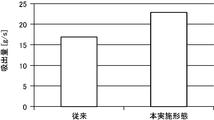
また、図12に示されるように、エゼクタ効果による排気ガスの吸出し量は、本実施形態の排気装置の方が従来の排気装置よりも多くなっている。
従って、本実施形態によれば、独立排気管5からの排気の吸出し量の増大を図って、エンジン出力を効果的に向上させることができる。
(第2実施形態)
次に第2実施形態について、図13~21を参照しつつ説明する。以下の説明では、第1実施形態と同様の構成については、同一の参照符号を付してその説明を適宜省略する。
次に第2実施形態について、図13~21を参照しつつ説明する。以下の説明では、第1実施形態と同様の構成については、同一の参照符号を付してその説明を適宜省略する。
本実施形態では、図16~18に示すように、独立排気管5a,5b,5cは、その下流端から上流側への所定の区間K2(図13参照。以下、「重複区間K2」と称する)において、独立排気管5aの断面円形の内部空間53aの一部と、独立排気管5bの断面円形の内部空間53bの一部と、独立排気管5cの断面円形の内部空間53cの一部とが互いに重複するとともに、その重複する割合が重複区間K2において上流側から下流側に向かって徐々に増加するように、ストレート部6の上流端に接続されている。本実施形態では、各独立排気管5の下流部の軸心L1は、図14に示されるように、ストレート部6の軸心L2上において1つの点Pで互いに交わっている。
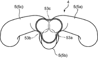
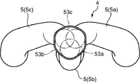
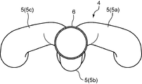
具体的には、本実施形態では、図16に示されるように、内部空間53aと、内部空間53bと、内部空間53cとが互いに僅かに重複している。ここで、図16に示される内部空間53a,53b,53cは、図13のXVI-XVI線断面付近の内部空間を示している。なお、図16に示す独立排気管5a,5b,5cの構造を理解しやすくするために、図16に示す各独立排気管5を斜め方向から見た斜視図を、見る方向を変えつつ図19~21に示している。そして、より下流側では、図17に示されるように、内部空間53aと、内部空間53bと、内部空間53cとの重複面積が、図16に示される重複面積よりも大きくなっている。ここで、図17に示される内部空間53a,53b,53cは、図13のXVII-XVII線断面付近の内部空間を示している。さらに下流側では、図18に示されるように、内部空間53aと、内部空間53bと、内部空間53cとの重複面積が、図17に示される重複面積よりも大きくなっている。ここで、図18に示される内部空間53a,53b,53cは、図13のXVIII-XVIII線断面付近の内部空間を示している。
より具体的には、図16~18に示されるように、独立排気管5a,5b,5cは、各々、重複区間K2において、その軸心L1方向から見て円弧状の管壁55を有する。そして、独立排気管5a,5b,5cの各管壁55の周方向端部が互いに接合されて、軸心L1方向から見て複数の膨出部(つまり円弧状の管壁55)を有する異形周壁57が形成されている。そして、当該異形周壁57は、その軸方向に直交する方向の断面が、上流側から下流側に向かって徐々に円形に近づき、下流端でストレート部6の上流端と同じ径の円形になって、ストレート部6の上流端に接続されている。本実施形態では、独立排気管5a,5b,5cの周壁55は、重複区間K2において、周壁55の径が次第に大きくなっている(図16~18中の二点鎖線円参照)。そして、図16~18に示されるように、互いの周壁55の接合部において、周壁55の外周面に対する接線同士がなす角度が、下流側に進むにつれて次第に小さくなっている。
本実施形態のストレート部6は、第1実施形態における突出部分62が除去された構造を有しており、その上端面が円形状となっている。
本実施形態においても、第1実施形態と同様に、各独立排気管5から排出された排気が、その流通形状を略円形に維持したままストレート部6に流入し、これにより、各独立排気管5から流入した排気が円形断面のストレート部6内全体に略均一に分布することになる。その結果、ストレート部6における下流側からの排気の逆流が上記従来の排気装置に比べて抑制される。これにより、独立排気管5からの排気の吸出し量の増大を行って、エンジン出力を効果的に向上させることができる。
(第3実施形態)
本発明の第3実施形態について、図22~27を参照しつつ説明する。以下の説明では、第1実施形態と同様の構成については、同一の参照符号を付してその説明を適宜省略する。
本発明の第3実施形態について、図22~27を参照しつつ説明する。以下の説明では、第1実施形態と同様の構成については、同一の参照符号を付してその説明を適宜省略する。
本実施形態では、混合管50は、その軸心上に、上流側から順に円錐台状部13、ストレート部6およびディフューザー部7を備えている。円錐台状部13は、下流側に延びるとともに下流側ほど流路面積が小さく、ディフューザー部7は、下流側ほど流路面積が大きくなっている。
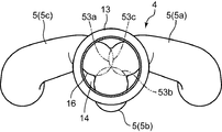
円錐台状部13は、その上流側端部に、円板状の端壁部14(図23参照)を有している。そして、この端壁部14に形成された開口部16に、各独立排気管5の下流側端部が接続されている。この開口部16は、図25~27に示されるように、端壁部14の中心周りに周方向に並ぶ3つの円弧の端部同士が接続されたような形状を有している。本実施形態では、各独立排気管5の下流部の軸心L1は、図23に示されるように、円錐台状部13の軸心L3上において1つの点Pで互いに交わっている。
本実施形態では、独立排気管5a,5b,5cは、その下流端から上流側への所定の区間K3(図22参照。以下、「重複区間K3」と称する)において、独立排気管5aの断面円形の内部空間53aの一部と、独立排気管5bの断面円形の内部空間53bの一部と、独立排気管5cの断面円形の内部空間53cの一部とが互いに重複するとともに、その重複する割合が重複区間K3において上流側から下流側に向かって徐々に増加するように、円錐台状部13の上流端に接続されている。
具体的には、重複区間K13では、図23に示されるように、独立排気管5a,5b,5cの各下流側端面51は、その軸心L1に対して傾斜した面で切り欠かれることにより形成されて互いに接合される部分51aと、円錐台状部13に接合される部分51bとを有する。
本実施形態においては、各独立排気管5から排出された排気が、その流通形状を略円形に維持したまま円錐台状部13に流入して混合され、その混合された排気が、その流通形状を略円形に維持したまま円形断面のストレート部6内に流入し、ストレート部6の全体に略均一に分布することになる。その結果、ストレート部6における下流側からの排気の逆流が上記従来の排気装置に比べて抑制される。これにより、独立排気管5からの排気の吸出し量の増大を行って、エンジン出力を効果的に向上させることができる。
なお、上記各実施形態は、4気筒エンジンに適用されているが、これに限定されるものではなく、6気筒エンジン、8気筒エンジン等に適用することも可能である。
以上説明した本発明をまとめると以下の通りである。
本発明は、複数の気筒を備えたエンジン本体を有するエンジンの前記エンジン本体に接続される排気装置であって、前記エンジン本体の各気筒の排気ポートまたは排気順序が連続しない複数の気筒の排気ポートにそれぞれ接続される断面円形の複数の独立排気管と、前記各独立排気管の下流端に接続されて各独立排気管を通過した排気が流入する断面円形の混合管と、を備え、前記各独立排気管は、その下流端から上流側への所定の区間でその断面円形の内部空間の一部が互いに重複するとともに、その重複する割合が上流側から下流側に向かって徐々に増加するように、前記混合管の上流端に接続されているものである。
本発明によれば、各独立排気管から排出された排気が、その流通形状を略円形に維持したまま混合管に流入するため、各独立排気管から流入した排気が円形断面の混合管内全体に略均一に分布することになる。その結果、下流側からの排気の逆流が抑制され、独立排気管からの排気の吸出し量の増大を図って、エンジン出力を向上させることができる。
本発明においては、前記混合管は、前記各独立排気管から流入した排気が集合する集合部を有し、当該集合部は、その軸方向全体において同じ内径を有することが好ましい。
この構成によれば、軸方向全体において同じ内径を有する集合部において、各独立排気管から流入した排気を混合管内でより確実に均一分布させることができ、下流側からの排気の逆流をより一層抑制することができる。
本発明においては、前記各独立排気管は、内部空間の一部が互いに重複する区間において、その軸心に対して傾斜した下流側端面を有するとともに、互いの下流側端面が向かい合うように配置され、前記混合管の上流側端部は、互いに向かい合う前記下流側端面の間の隙間を埋めるように周方向の一部が上流側に突出する形状を有し、前記各独立排気管の下流側端面と前記混合管の上流側端部とが互いに接合されていることが好ましい。
この構成によれば、独立排気管の下流端および集合部の上流端を比較的簡単な構造とすることができ、比較的簡単に製造することができる。
前記各独立排気管は、前記各独立排気管は、内部空間の一部が互いに重複する区間において、軸心方向から見て円弧状の管壁を有するとともに、当該管壁の周方向端部が互いに接合されて、前記混合管側から見て複数の膨出部を有する異形周壁を形成しており、当該異形周壁は、その軸方向に直交する方向の断面が上流側から下流側に向かって徐々に円形に近づき、下流端で前記混合管の上流端と同じ径の円形になって、当該混合管の上流端に接続されることが好ましい。
この構成によれば、独立排気管から混合管によりスムーズに排気を流入させることができる。
Claims (4)
- 複数の気筒を備えたエンジン本体を有するエンジンの前記エンジン本体に接続された排気装置であって、
前記エンジン本体の各気筒の排気ポートまたは排気順序が連続しない複数の気筒の排気ポートにそれぞれ接続される断面円形の複数の独立排気管と、
前記各独立排気管の下流端に接続されて各独立排気管を通過した排気が流入する断面円形の混合管と、を備え、
前記各独立排気管は、その下流端から上流側への所定の区間でその断面円形の内部空間の一部が互いに重複するとともに、その重複する割合が上流側から下流側に向かって徐々に増加するように、前記混合管の上流端に接続されている、ことを特徴とする多気筒エンジンの排気装置。 - 請求項1に記載の多気筒エンジンの排気装置において、
前記混合管は、前記各独立排気管から流入した排気が集合する集合部を有し、当該集合部は、その軸方向全体において同じ内径を有することを特徴とする多気筒エンジンの排気装置。 - 請求項1又は2に記載の多気筒エンジンの排気装置において、
前記各独立排気管は、内部空間の一部が互いに重複する区間において、その軸心に対して傾斜した下流側端面を有するとともに、互いの下流側端面が向かい合うように配置され、
前記混合管の上流側端部は、互いに向かい合う前記下流側端面の間の隙間を埋めるように周方向の一部が上流側に突出する形状を有し、
前記各独立排気管の下流側端面と前記混合管の上流側端部とが互いに接合されていることを特徴とする多気筒エンジンの排気装置。 - 請求項1又は2に記載の多気筒エンジンの排気装置において、
前記各独立排気管は、内部空間の一部が互いに重複する区間において、軸心方向から見て円弧状の管壁を有するとともに、当該管壁の周方向端部が互いに接合されて、前記混合管側から見て複数の膨出部を有する異形周壁を形成しており、
前記異形周壁は、その軸方向に直交する方向の断面が上流側から下流側に向かって徐々に円形に近づき、下流端で前記混合管の上流端と同じ径の円形になって、当該混合管の上流端に接続されることを特徴とする多気筒エンジンの排気装置。
Priority Applications (3)
| Application Number | Priority Date | Filing Date | Title |
|---|---|---|---|
| DE112016005393.2T DE112016005393B4 (de) | 2015-11-25 | 2016-11-09 | Auslassvorrichtung eines Mehrzylindermotors |
| US15/761,206 US10598074B2 (en) | 2015-11-25 | 2016-11-09 | Exhaust device of multiple-cylinder engine |
| CN201680053703.8A CN108350794B (zh) | 2015-11-25 | 2016-11-09 | 多缸发动机的排气装置 |
Applications Claiming Priority (2)
| Application Number | Priority Date | Filing Date | Title |
|---|---|---|---|
| JP2015229584A JP6361638B2 (ja) | 2015-11-25 | 2015-11-25 | 多気筒エンジンの排気装置 |
| JP2015-229584 | 2016-11-25 |
Publications (1)
| Publication Number | Publication Date |
|---|---|
| WO2017090433A1 true WO2017090433A1 (ja) | 2017-06-01 |
Family
ID=58764009
Family Applications (1)
| Application Number | Title | Priority Date | Filing Date |
|---|---|---|---|
| PCT/JP2016/083290 Ceased WO2017090433A1 (ja) | 2015-11-25 | 2016-11-09 | 多気筒エンジンの排気装置 |
Country Status (5)
| Country | Link |
|---|---|
| US (1) | US10598074B2 (ja) |
| JP (1) | JP6361638B2 (ja) |
| CN (1) | CN108350794B (ja) |
| DE (1) | DE112016005393B4 (ja) |
| WO (1) | WO2017090433A1 (ja) |
Families Citing this family (4)
| Publication number | Priority date | Publication date | Assignee | Title |
|---|---|---|---|---|
| US11913390B2 (en) | 2019-08-30 | 2024-02-27 | Bombardier Recreational Products Inc. | Engine assembly and method for controlling an engine |
| WO2021038538A2 (en) * | 2019-08-30 | 2021-03-04 | Bombardier Recreational Products Inc. | Engine assembly and method for controlling an engine |
| US11732637B2 (en) * | 2020-12-17 | 2023-08-22 | Brp-Rotax Gmbh & Co. Kg | Engine assembly for a vehicle having a compressor |
| JP7694545B2 (ja) * | 2022-12-01 | 2025-06-18 | トヨタ自動車株式会社 | 内燃機関の排気浄化装置 |
Citations (5)
| Publication number | Priority date | Publication date | Assignee | Title |
|---|---|---|---|---|
| JPS6046248B2 (ja) * | 1980-11-15 | 1985-10-15 | 勇 藤壷 | 複数の排気管の集合部 |
| JPS61160512A (ja) * | 1985-01-08 | 1986-07-21 | Yamaha Motor Co Ltd | 車両用エンジンのエキゾ−ストパイプ集合部構造 |
| US6647714B1 (en) * | 2002-05-29 | 2003-11-18 | Ghl Motorsports, L.L.C. | Exhaust header system |
| US20110154812A1 (en) * | 2009-12-29 | 2011-06-30 | Butler Boyd L | Oval-to-round exhaust collector system |
| JP2013032753A (ja) * | 2011-08-03 | 2013-02-14 | Mazda Motor Corp | 多気筒エンジンの吸排気装置 |
Family Cites Families (8)
| Publication number | Priority date | Publication date | Assignee | Title |
|---|---|---|---|---|
| US3507301A (en) | 1966-04-21 | 1970-04-21 | Robert H Larson | Collector and method of making the same |
| US4796426A (en) | 1982-07-06 | 1989-01-10 | Feuling James J | High efficiency transition element positioned intermediate multi-cylinder exhaust system and secondary pipe assemblies |
| DE3506183A1 (de) | 1985-02-22 | 1986-08-28 | Friedrich Boysen Gmbh & Co Kg, 7272 Altensteig | Abgasrohrkruemmer |
| JP2856705B2 (ja) | 1996-05-08 | 1999-02-10 | 株式会社三五 | 合流管とその製造方法 |
| JP2009062879A (ja) | 2007-09-06 | 2009-03-26 | Toshiba Carrier Corp | 密閉型圧縮機 |
| JP2013054609A (ja) | 2011-09-05 | 2013-03-21 | Tamagawa Seiki Co Ltd | タッチパネルにおける押し込み感触発生構造、タッチパネル、情報端末装置および感触発生用シート |
| JP5978584B2 (ja) | 2011-10-04 | 2016-08-24 | マツダ株式会社 | 多気筒エンジンの排気装置 |
| CN203009031U (zh) | 2012-06-11 | 2013-06-19 | 山东交通学院 | 一种模件式二级排气管系涡轮增压系统 |
-
2015
- 2015-11-25 JP JP2015229584A patent/JP6361638B2/ja not_active Expired - Fee Related
-
2016
- 2016-11-09 US US15/761,206 patent/US10598074B2/en active Active
- 2016-11-09 WO PCT/JP2016/083290 patent/WO2017090433A1/ja not_active Ceased
- 2016-11-09 DE DE112016005393.2T patent/DE112016005393B4/de active Active
- 2016-11-09 CN CN201680053703.8A patent/CN108350794B/zh not_active Expired - Fee Related
Patent Citations (5)
| Publication number | Priority date | Publication date | Assignee | Title |
|---|---|---|---|---|
| JPS6046248B2 (ja) * | 1980-11-15 | 1985-10-15 | 勇 藤壷 | 複数の排気管の集合部 |
| JPS61160512A (ja) * | 1985-01-08 | 1986-07-21 | Yamaha Motor Co Ltd | 車両用エンジンのエキゾ−ストパイプ集合部構造 |
| US6647714B1 (en) * | 2002-05-29 | 2003-11-18 | Ghl Motorsports, L.L.C. | Exhaust header system |
| US20110154812A1 (en) * | 2009-12-29 | 2011-06-30 | Butler Boyd L | Oval-to-round exhaust collector system |
| JP2013032753A (ja) * | 2011-08-03 | 2013-02-14 | Mazda Motor Corp | 多気筒エンジンの吸排気装置 |
Also Published As
| Publication number | Publication date |
|---|---|
| DE112016005393B4 (de) | 2022-04-07 |
| CN108350794A (zh) | 2018-07-31 |
| CN108350794B (zh) | 2020-09-11 |
| JP2017096180A (ja) | 2017-06-01 |
| JP6361638B2 (ja) | 2018-07-25 |
| US20180266302A1 (en) | 2018-09-20 |
| DE112016005393T5 (de) | 2018-08-09 |
| US10598074B2 (en) | 2020-03-24 |
Similar Documents
| Publication | Publication Date | Title |
|---|---|---|
| JP4725656B2 (ja) | 多気筒エンジンの排気通路構造 | |
| JP5915104B2 (ja) | 多気筒エンジンの排気装置 | |
| JP5870488B2 (ja) | 多気筒エンジンの吸排気装置 | |
| CN103958858B (zh) | 多气缸发动机的排气装置 | |
| JP6361638B2 (ja) | 多気筒エンジンの排気装置 | |
| JP2011214469A (ja) | 多気筒エンジンの排気装置 | |
| JP5375151B2 (ja) | 多気筒エンジンの排気通路構造 | |
| JP6321827B2 (ja) | 排気ガスターボチャージャを有する4ストローク往復内燃エンジン | |
| JP5891943B2 (ja) | 多気筒エンジンの排気装置 | |
| JP5919743B2 (ja) | 多気筒エンジンの排気制御装置 | |
| JP5978584B2 (ja) | 多気筒エンジンの排気装置 | |
| JP2013072366A (ja) | 多気筒エンジンの吸排気装置 | |
| JP5326630B2 (ja) | 多気筒エンジンの排気通路構造 | |
| JP5998503B2 (ja) | 多気筒エンジンの吸排気装置 | |
| JP5531923B2 (ja) | 多気筒エンジンの吸排気装置 | |
| JP2013007270A (ja) | 内燃機関のポート | |
| JP5953786B2 (ja) | 多気筒エンジンの排気装置 | |
| JP5817302B2 (ja) | 多気筒エンジンの吸排気装置 | |
| JP5794037B2 (ja) | 多気筒エンジンの吸排気装置 | |
| JP5472050B2 (ja) | 多気筒エンジンの排気装置 | |
| JP5531922B2 (ja) | 多気筒エンジンの吸排気装置 | |
| JP5703782B2 (ja) | 多気筒エンジンの吸排気装置 | |
| JP5673214B2 (ja) | 多気筒エンジンの吸排気装置 |
Legal Events
| Date | Code | Title | Description |
|---|---|---|---|
| 121 | Ep: the epo has been informed by wipo that ep was designated in this application |
Ref document number: 16868381 Country of ref document: EP Kind code of ref document: A1 |
|
| WWE | Wipo information: entry into national phase |
Ref document number: 15761206 Country of ref document: US |
|
| WWE | Wipo information: entry into national phase |
Ref document number: 112016005393 Country of ref document: DE |
|
| 122 | Ep: pct application non-entry in european phase |
Ref document number: 16868381 Country of ref document: EP Kind code of ref document: A1 |