WO2017086027A1 - 撮像装置、および、撮像システム - Google Patents
撮像装置、および、撮像システム Download PDFInfo
- Publication number
- WO2017086027A1 WO2017086027A1 PCT/JP2016/078555 JP2016078555W WO2017086027A1 WO 2017086027 A1 WO2017086027 A1 WO 2017086027A1 JP 2016078555 W JP2016078555 W JP 2016078555W WO 2017086027 A1 WO2017086027 A1 WO 2017086027A1
- Authority
- WO
- WIPO (PCT)
- Prior art keywords
- pair
- distance
- imaging
- image
- unit
- Prior art date
- Legal status (The legal status is an assumption and is not a legal conclusion. Google has not performed a legal analysis and makes no representation as to the accuracy of the status listed.)
- Ceased
Links
Images







Classifications
-
- G—PHYSICS
- G01—MEASURING; TESTING
- G01B—MEASURING LENGTH, THICKNESS OR SIMILAR LINEAR DIMENSIONS; MEASURING ANGLES; MEASURING AREAS; MEASURING IRREGULARITIES OF SURFACES OR CONTOURS
- G01B11/00—Measuring arrangements characterised by the use of optical techniques
- G01B11/02—Measuring arrangements characterised by the use of optical techniques for measuring length, width or thickness
- G01B11/026—Measuring arrangements characterised by the use of optical techniques for measuring length, width or thickness by measuring distance between sensor and object
-
- G—PHYSICS
- G01—MEASURING; TESTING
- G01C—MEASURING DISTANCES, LEVELS OR BEARINGS; SURVEYING; NAVIGATION; GYROSCOPIC INSTRUMENTS; PHOTOGRAMMETRY OR VIDEOGRAMMETRY
- G01C3/00—Measuring distances in line of sight; Optical rangefinders
- G01C3/02—Details
- G01C3/06—Use of electric means to obtain final indication
-
- G—PHYSICS
- G01—MEASURING; TESTING
- G01B—MEASURING LENGTH, THICKNESS OR SIMILAR LINEAR DIMENSIONS; MEASURING ANGLES; MEASURING AREAS; MEASURING IRREGULARITIES OF SURFACES OR CONTOURS
- G01B11/00—Measuring arrangements characterised by the use of optical techniques
- G01B11/002—Measuring arrangements characterised by the use of optical techniques for measuring two or more coordinates
-
- G—PHYSICS
- G01—MEASURING; TESTING
- G01B—MEASURING LENGTH, THICKNESS OR SIMILAR LINEAR DIMENSIONS; MEASURING ANGLES; MEASURING AREAS; MEASURING IRREGULARITIES OF SURFACES OR CONTOURS
- G01B11/00—Measuring arrangements characterised by the use of optical techniques
- G01B11/24—Measuring arrangements characterised by the use of optical techniques for measuring contours or curvatures
-
- G—PHYSICS
- G01—MEASURING; TESTING
- G01C—MEASURING DISTANCES, LEVELS OR BEARINGS; SURVEYING; NAVIGATION; GYROSCOPIC INSTRUMENTS; PHOTOGRAMMETRY OR VIDEOGRAMMETRY
- G01C3/00—Measuring distances in line of sight; Optical rangefinders
- G01C3/10—Measuring distances in line of sight; Optical rangefinders using a parallactic triangle with variable angles and a base of fixed length in the observation station, e.g. in the instrument
- G01C3/14—Measuring distances in line of sight; Optical rangefinders using a parallactic triangle with variable angles and a base of fixed length in the observation station, e.g. in the instrument with binocular observation at a single point, e.g. stereoscopic type
-
- G—PHYSICS
- G06—COMPUTING OR CALCULATING; COUNTING
- G06F—ELECTRIC DIGITAL DATA PROCESSING
- G06F3/00—Input arrangements for transferring data to be processed into a form capable of being handled by the computer; Output arrangements for transferring data from processing unit to output unit, e.g. interface arrangements
- G06F3/01—Input arrangements or combined input and output arrangements for interaction between user and computer
- G06F3/017—Gesture based interaction, e.g. based on a set of recognized hand gestures
-
- G—PHYSICS
- G06—COMPUTING OR CALCULATING; COUNTING
- G06F—ELECTRIC DIGITAL DATA PROCESSING
- G06F3/00—Input arrangements for transferring data to be processed into a form capable of being handled by the computer; Output arrangements for transferring data from processing unit to output unit, e.g. interface arrangements
- G06F3/01—Input arrangements or combined input and output arrangements for interaction between user and computer
- G06F3/03—Arrangements for converting the position or the displacement of a member into a coded form
- G06F3/0304—Detection arrangements using opto-electronic means
-
- H—ELECTRICITY
- H04—ELECTRIC COMMUNICATION TECHNIQUE
- H04N—PICTORIAL COMMUNICATION, e.g. TELEVISION
- H04N13/00—Stereoscopic video systems; Multi-view video systems; Details thereof
- H04N13/20—Image signal generators
- H04N13/204—Image signal generators using stereoscopic image cameras
- H04N13/239—Image signal generators using stereoscopic image cameras using two two-dimensional [2D] image sensors having a relative position equal to or related to the interocular distance
-
- H—ELECTRICITY
- H04—ELECTRIC COMMUNICATION TECHNIQUE
- H04N—PICTORIAL COMMUNICATION, e.g. TELEVISION
- H04N23/00—Cameras or camera modules comprising electronic image sensors; Control thereof
- H04N23/60—Control of cameras or camera modules
- H04N23/61—Control of cameras or camera modules based on recognised objects
-
- H—ELECTRICITY
- H04—ELECTRIC COMMUNICATION TECHNIQUE
- H04N—PICTORIAL COMMUNICATION, e.g. TELEVISION
- H04N23/00—Cameras or camera modules comprising electronic image sensors; Control thereof
- H04N23/60—Control of cameras or camera modules
- H04N23/61—Control of cameras or camera modules based on recognised objects
- H04N23/611—Control of cameras or camera modules based on recognised objects where the recognised objects include parts of the human body
-
- H—ELECTRICITY
- H04—ELECTRIC COMMUNICATION TECHNIQUE
- H04N—PICTORIAL COMMUNICATION, e.g. TELEVISION
- H04N23/00—Cameras or camera modules comprising electronic image sensors; Control thereof
- H04N23/60—Control of cameras or camera modules
- H04N23/695—Control of camera direction for changing a field of view, e.g. pan, tilt or based on tracking of objects
-
- H—ELECTRICITY
- H04—ELECTRIC COMMUNICATION TECHNIQUE
- H04N—PICTORIAL COMMUNICATION, e.g. TELEVISION
- H04N13/00—Stereoscopic video systems; Multi-view video systems; Details thereof
- H04N2013/0074—Stereoscopic image analysis
- H04N2013/0081—Depth or disparity estimation from stereoscopic image signals
Definitions
- This technology relates to an imaging apparatus and an imaging system. Specifically, the present invention relates to an imaging apparatus that measures a distance to an object and an imaging system.
- a twin-lens imaging device provided with a pair of imaging elements has been used for the purpose of imaging a stereo image.
- an image shift amount is generated due to parallax between an image obtained by one of the pair of imaging elements and an image obtained by the other. Since this image shift amount is known to change according to the distance to the object, the distance can be calculated from this image shift amount.
- an imaging apparatus that arranges a pair of imaging elements so that optical axes perpendicular to the respective light receiving surfaces are parallel to each other and measures a distance D from the image shift amount Z to an object using a predetermined relational expression. It has been proposed (see, for example, Patent Document 1).
- the image shift amount Z increases as the interval (hereinafter referred to as “baseline length”) B between the pair of image sensors increases, and decreases as the distance D increases.
- the image shift amount Z decreases as the distance D increases, and the distance measurement accuracy may decrease.
- the image shift amount Z can be relatively increased to improve the distance measurement accuracy.
- the apparatus may be increased in size. Thus, it is difficult to achieve both the miniaturization of the device and the improvement of the ranging accuracy.
- the present technology has been created in view of such a situation, and aims to achieve both miniaturization of the device and improvement of ranging accuracy in the device for measuring the distance to the object.
- the present technology has been made to solve the above-described problems.
- the first side surface of the present technology includes a pair of imaging elements whose axes perpendicular to the respective light receiving surfaces intersect each other and the pair of imaging elements.
- An imaging apparatus including a distance measuring unit that measures a distance to an object based on parallax obtained from a pair of captured images. This brings about the effect that the distance is measured based on the parallax obtained from the pair of images.
- an imaging lens that collects light and guides the light to the pair of imaging elements may be further provided. Accordingly, there is an effect that a pair of images are captured by the pair of imaging lenses that receive the light collected by one imaging lens.
- the first aspect further includes a pair of imaging lenses, and one of the pair of imaging lenses condenses light and guides it to one of the pair of imaging elements, and the other of the pair of imaging lenses. May condense light and guide it to the other of the pair of imaging elements. Thereby, a pair of images is picked up by a pair of imaging lenses that receive light collected by the pair of imaging lenses.
- a lens barrel may be further provided, and one light receiving surface of the pair of imaging elements may be parallel to a bottom surface of the lens barrel.
- one light-receiving surface brings about the effect
- the distance measuring unit may measure the distance from an image shift amount between one of the pair of images and the other. As a result, the distance is measured from the image shift amount.
- the distance measuring unit may measure the distance from a distortion amount with respect to one of the pair of images. This brings about the effect that the distance is measured from the amount of distortion with respect to one of the pair of images.
- the second aspect of the present technology is based on a pair of imaging elements whose axes perpendicular to the respective light receiving surfaces intersect each other and a parallax obtained from a pair of images captured by the pair of imaging elements.
- An imaging system comprising: a distance measuring unit that measures a distance to an object; and a processing unit that performs a process of recognizing the shape of the object based on the measured distance and the pair of images. This brings about the effect that the distance is measured based on the parallax obtained from the pair of images.
- the apparatus for measuring the distance to the object it is possible to achieve an excellent effect that both the downsizing of the apparatus and the improvement of the ranging accuracy can be achieved.
- the effects described here are not necessarily limited, and may be any of the effects described in the present disclosure.
- 1 is an example of an external view of an electronic device according to a first embodiment of the present technology. It is a block diagram showing an example of 1 composition of electronic equipment in a 1st embodiment of this art. It is a block diagram showing an example of 1 composition of a processing part in a 1st embodiment of this art. It is a top view showing an example of 1 composition of an optical system in a 1st embodiment of this art. It is a figure for demonstrating the relationship between the inclination of the lens and parallax in 1st Embodiment of this technique. It is a figure for demonstrating the method to calculate distance from the parallax in 1st Embodiment of this technique.
- FIG. 7 is a flowchart illustrating an example of an operation of the electronic device according to the first embodiment of the present technology. It is a top view showing an example of 1 composition of an optical system in the 1st modification of a 1st embodiment of this art. It is a block diagram showing an example of 1 composition of electronic equipment in the 2nd modification of a 1st embodiment of this art. It is a block diagram showing an example of 1 composition of an operation processing part in the 2nd modification of a 1st embodiment of this art.
- First embodiment an example in which a pair of image sensors whose optical axes intersect each other is provided
- Second Embodiment Example in which a pair of imaging elements having optical axes intersecting each other is provided in an optical system having one lens
- Third Embodiment Example in which a camera module provided with a pair of imaging elements whose optical axes intersect with each other is arranged outside the apparatus
- FIG. 1 is an example of an external view of an electronic device 100 according to the first embodiment.
- a mobile device having an imaging function such as a smartphone or a tablet terminal is assumed.
- Standard lenses 121 and 122 are arranged at a predetermined interval on the front surface of the electronic apparatus 100 on which the display is provided. Note that the standard lenses 121 and 122 may be arranged not on the front surface of the electronic device 100 but on the back surface where the display is not provided.
- Standard lenses 121 and 122 are lenses that condense light and guide it to the image sensor.
- the angle of view of these lenses is a certain value (for example, 60 degrees) or less.
- the standard lenses 121 and 122 are examples of the imaging lens described in the claims.
- the electronic device 100 is an example of an imaging device described in the claims.
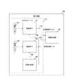
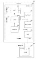
- FIG. 2 is a block diagram illustrating a configuration example of the electronic device 100 according to the first embodiment.
- the electronic device 100 includes a camera module 110 and an arithmetic processing unit 150.
- the camera module 110 includes standard lenses 121 and 122, image sensors 131 and 132, and a synchronization control unit 140.
- the image sensor 131 is for photoelectrically converting the light from the standard lens 121 and capturing image data.
- the image sensor 132 photoelectrically converts light from the standard lens 122 and images image data.
- These imaging elements include a plurality of photoelectric conversion elements arranged in a two-dimensional lattice pattern on the light receiving surface. Further, these image sensors 131 and 132 are arranged such that optical axes perpendicular to the respective light receiving surfaces intersect each other. However, in FIG. 2, for convenience of description, the optical axes are parallel to each other, unlike the mounting.
- the standard lens 121 and the image sensor 131 are arranged on the right side when viewed from the back of the electronic apparatus 100, and the standard lens 122 and the image sensor 132 are arranged on the left side.
- the image sensor 131 supplies the captured image data as right image data to the arithmetic processing unit 150 via the signal line 118.
- the image sensor 132 supplies the captured image data as left image data to the arithmetic processing unit 150 via the signal line 119.
- Each of the right image data and the left image data includes a plurality of pixels arranged in a two-dimensional grid.
- the synchronization control unit 140 synchronizes the imaging operations of the imaging elements 131 and 132. For example, when an application for performing gesture recognition is executed, the synchronization control unit 140 starts generating a vertical synchronization signal having a constant frequency. The synchronization control unit 140 transmits the vertical synchronization signal to the image sensors 131 and 132 via the signal lines 148 and 149. The image sensors 131 and 132 capture images in synchronization with the common vertical synchronization signal.
- the synchronization control unit 140 is arranged inside the camera module 110, it may be arranged outside the camera module 110. In addition, when only imaging of a stationary object is assumed, a configuration in which the synchronization control unit 140 is not provided can be employed.
- the standard lenses 121 and 122 and the image sensors 131 and 132 are arranged in the same camera module, they may be arranged in a plurality of modules. For example, the standard lens 121 and the image sensor 131 may be arranged in the right camera module, and the standard lens 122 and the image sensor 132 may be arranged in the left camera module.
- the calculation processing unit 150 performs predetermined calculation processing based on the left image data and the right image data.
- This arithmetic processing includes processing for measuring the distance from the image shift amount between the left image data and the right image data.
- the electronic device 100 measures the distance based on the data obtained by the imaging elements 131 and 132 in which the photoelectric conversion elements are arranged in a two-dimensional lattice shape, but a pair of linearly arranged photoelectric conversion elements. Ranging may be performed based on data obtained by the image sensor.
- An image sensor in which photoelectric conversion elements are arranged in a straight line in this way is also called a linear image sensor.
- the imaging elements 131 and 132 may not be provided, or they may be provided separately from the linear image sensor.
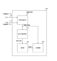
- FIG. 3 is a block diagram illustrating a configuration example of the arithmetic processing unit 150 according to the first embodiment.
- the arithmetic processing unit 150 includes a feature point extraction unit 151, an image shift amount acquisition unit 152, a distance measurement unit 153, and a UI (User Interface) processing unit 154.
- the feature point extraction unit 151 extracts feature points in each of the left image data and the right image data.
- the feature point means a portion where the color and brightness greatly change, such as an intersection (corner) of edges.
- a Harris operator is extracted as a feature point by a combination of first-order differentiation and Gaussian smoothing.
- a Moravec operator that directly evaluates the variance of luminance values in each direction is extracted as a feature point.
- a feature point is extracted by a SUSAN (Smallest Univalue Segment Assimilating Nucleus) operator that counts the number of pixels equal to or greater than an arbitrary threshold in the mask using a circular mask. Note that an algorithm different from the above may be used as long as the feature points can be extracted.
- the feature point extraction unit 151 generates, for each of the left image data and the right image data, feature point information that includes, for each feature point, the coordinates of the feature points in the image and identification information for identifying the feature points.
- the data is supplied to the acquisition unit 152 and the UI processing unit 154.
- the image shift amount acquisition unit 152 acquires the image shift amount between the left image data and the right image data based on the feature point information. For example, the image shift amount acquisition unit 152 obtains a feature point in the right image data corresponding to the feature point of at least one feature point in the left image data.
- the image shift amount acquisition unit 152 obtains, for each feature point, a feature amount of a region having a certain shape (such as a circle) centered on the feature point. , Feature points whose feature amounts are higher than a certain value are associated with each other. As the feature amount, for example, a vector indicating the direction of the luminance gradient is obtained. Note that the image shift amount acquisition unit 152 may perform matching using an algorithm other than this method.
- the image deviation amount acquisition unit 152 calculates the distance (Euclidean distance or the like) between the corresponding feature points for each corresponding feature point pair as the image deviation amount Z, and supplies the calculated distance to the distance measurement unit 153.
- the distance measuring unit 153 measures the distance D from the image shift amount Z for each feature point.
- the distance measuring unit 153 supplies the measured distance D to the UI processing unit 154.
- the image shift amount acquisition unit 152 calculates the distance D only for the feature points, but may calculate the distance D for all the pixels.
- the UI processing unit 154 performs input processing related to the user interface based on the coordinates and distance D for each feature point. For example, the UI processing unit 154 recognizes the shape of the human body from the coordinates for each feature point and the distance D, and detects the shape or temporal change in the shape as a gesture. The UI processing unit 154 executes input processing corresponding to the detected gesture. For example, a swipe process of moving (swiping) the screen is associated in advance with the gesture “shake the right hand to the left and right”, and the UI processing unit 154 performs the swipe process when the gesture is recognized.
- the UI processing unit 154 is an example of a processing unit described in the claims.
- the arithmetic processing unit 150 obtains the image shift amount Z from the matched feature points, but the image shift amount Z may be obtained by another method.
- the image shift amount acquisition unit 152 may obtain the image shift amount Z using, for example, a phase-only correlation (POC: Phase Only Correlation) method using Fourier transform. When this POC method is used, it is not necessary to extract feature points in ranging.
- POC Phase Only Correlation
- the arithmetic processing unit 150 uses the distance D for UI processing, it may be used for other processing. For example, it may be used for AF (Auto-Focus) processing or depth map generation processing.
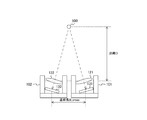
- FIG. 4 is a top view showing a configuration example of the optical system according to the first embodiment.
- This optical system includes standard lenses 121 and 122, imaging elements 131 and 132, and lens barrels 101 and 102.
- a standard lens 121 and an image sensor 131 are arranged in the lens barrel 101, and a standard lens 122 and an image sensor 132 are arranged in the lens barrel 102.
- FIG. 2 is a top view of the optical system as viewed from a predetermined direction parallel to the display surface of the electronic device 100.
- the standard lens 121 is arranged so that its lens surface is substantially parallel to the light receiving surface of the image sensor 131. Further, the standard lens 122 is arranged so that its lens surface is substantially parallel to the light receiving surface of the image sensor 132.
- the image sensors 131 and 132 are arranged so that optical axes perpendicular to the respective light receiving surfaces intersect each other.
- the image sensor 131 is arranged such that the bottom surface of the lens barrel 101 and the light receiving surface of the image sensor 131 form a predetermined angle, and the bottom surface of the lens barrel 102 and the light receiving surface of the image sensor 132 form a predetermined angle.
- the image sensor 132 is disposed on the front side.
- each representative point for example, the center of the light receiving surface
- depth direction a direction perpendicular to the display surface
- the distance between the representative points of the imaging elements 131 and 132 in the direction perpendicular to the depth direction is defined as a base line length B_cross.
- the angle when viewing a certain object 500 from each of the imaging elements 131 and 132 arranged at intervals of the baseline length B_cross differs between the left imaging element 132 and the right imaging element 131, and this angle This difference is called parallax.
- This parallax causes an image shift amount Z.
- This image shift amount Z (parallax) changes according to the distance D from the standard lenses 121 and 122 to the predetermined object 500 in the depth direction. Therefore, the distance D can be obtained from the image shift amount Z.
- f indicates the focal length of the standard lenses 121 and 122.
- the unit of the distance D, the focal length f, and the baseline length B is, for example, meters (m).
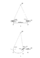
- FIG. 5 is a diagram for explaining the relationship between the tilt of the lens and the parallax in the first embodiment.
- a is a top view of an optical system of a comparative example in which the image sensors 131 and 132 are arranged so that their optical axes are parallel to each other.
- the distance between the center coordinate X1 of the image sensor 131 and the center coordinate X2 of the image sensor 132 in the direction perpendicular to the depth direction is defined as a base line length B_para.
- This baseline length B_para is longer than the baseline length B_cross.
- an angle formed by the light receiving surface with respect to a straight line connecting a certain object 500 and the center of the image sensor 131 is R_para.
- B in FIG. 5 is a top view of the optical system when the image sensor 131 is tilted.
- a configuration is assumed in which the light receiving surface of the image sensor 131 is inclined by an inclination angle R_tilt with respect to a direction perpendicular to the depth direction. Then, it is assumed that the tilted image sensor 131 is translated toward the image sensor 132 and the angle when the object 500 is viewed from the image sensor 131 at a certain position X3 is R_para. At this position X3, the angle at which the object 500 is viewed from the image sensor 131 is the same as that before the tilt, so that the same image as a in FIG.
- FIG. 6 is a diagram for explaining a method for calculating the distance from the parallax according to the first embodiment.
- the image sensor 132 is further tilted by an inclination angle R_tilt in the opposite direction to the image sensor 131 in the state of b in FIG. 5 and translated in the opposite direction by the same distance as the image sensor 131.
- the angle at which the object 500 is viewed from the image sensor 132 is the same as that before the tilt, so that the same image as that before the tilt in FIG.
- a distance between X3 and X4 after the inclination is defined as a base line length B_cross.
- the baseline length B_cross is shorter than the baseline length B_para, the same image as before the tilt is formed on the image sensors 131 and 132, and therefore the image shift amount Z is the same as before the tilt. Since the image shift amount Z is the same, the distance measurement accuracy is the same when the image sensors 131 and 132 are not tilted and when they are tilted.
- the base line length can be shortened without lowering the ranging accuracy.
- the electronic device 100 can be reduced in size.
- the image pickup devices 131 and 132 are arranged so that the optical axes are parallel with the base length B_cross, the image shift amount Z is reduced and the ranging accuracy is lowered. That is, when the optical axes of the imaging elements 131 and 132 are crossed, the image shift amount Z can be increased by B_para / B_cross times without changing the base line length, compared to the case where the optical axes are parallel. Thereby, ranging accuracy can be improved. In this way, it is possible to achieve both reduction in size of the electronic device 100 and improvement in distance measurement accuracy.
- the baseline length B_para can be calculated from the inclination angle R_tilt and the baseline length B_cross using a trigonometric function.
- FIG. 7 is a diagram illustrating an example of the left image data and the right image data in the first embodiment.
- a is an example of the left image data 510
- b in the figure is an example of the right image data 520.
- the black circles in these image data indicate feature points.
- the feature point extraction unit 151 extracts feature points 511 and the like in the left image data 510, and extracts feature points 521 and the like in the right image data 520. Then, the image shift amount acquisition unit 152 performs feature point matching. For example, it is assumed that the feature point 511 of the left image data is associated with the feature point 521 of the right image data. The image shift amount acquisition unit 152 acquires the distance between the corresponding pair of feature points as the image shift amount Z.
- FIG. 8 is a diagram for explaining the distance error in the first embodiment.
- a in the same figure is a figure which shows an example of the distance error in the comparative example which has arrange
- a solid radial line indicates an optical path of light incident on the image sensor.
- the angles formed between the respective optical paths and the light receiving surface are different from each other by dR.
- White circles 501 and 502 indicate objects to be measured.
- a distance error dD_para1 from the black circle 503 corresponding to the angle + dR to the black circle 504 corresponding to the angle ⁇ dR occurs.
- a distance error dD_para2 also occurs for the white circle 502.
- FIG. 8 is a diagram illustrating an example of a distance error in the optical system in which the imaging elements 131 and 132 having the intersecting optical axes are arranged.
- the positions of the white circles 501 and 502 are the same as a in FIG.
- the distance between the black circle 503 corresponding to the angle + dR and the black circle 504 corresponding to the angle ⁇ dR becomes close as illustrated in FIG. Decreases from dD_para1 to dD_cross1.
- the distance error when measuring the white circle 502 also decreases from dD_para2 to dD_cross2. In this way, by intersecting the optical axes, the distance measurement accuracy is improved as compared with a configuration in which the optical axes are not intersected.
- FIG. 9 is a flowchart illustrating an example of the operation of the electronic device 100 according to the first embodiment. This operation is started, for example, when a predetermined application for performing user interface processing is executed.
- the electronic apparatus 100 captures the left image data and the right image data (step S901), and extracts feature points from the image data (step S902).
- the electronic apparatus 100 performs feature point matching and acquires the distance between the corresponding pair of feature points as the image shift amount Z (step S903).
- the electronic apparatus 100 measures the distance D from the image shift amount Z using Expression 2 (Step S904).
- the electronic device 100 performs user interface processing based on the obtained distance D and the coordinates of the feature points (step S905). After step S905, the electronic device 100 repeatedly executes step S901 and subsequent steps.
- the imaging elements 131 and 132 are arranged so that the optical axes intersect with each other, the image is compared with a configuration in which the optical axes are arranged in parallel.
- the amount of deviation can be increased.
- ranging accuracy can be improved.
- the apparatus can be reduced in size.
- both the image sensors 131 and 132 are inclined with respect to the bottom surfaces of the lens barrels 101 and 102.
- a support member for supporting the inclined image sensor between the lens barrel and the image sensor which may increase the number of components.
- the electronic device 100 according to the first modification of the first embodiment is different from the first embodiment in that the increase in the number of parts of the optical system and the displacement are suppressed.
- FIG. 10 is a top view showing an example of the configuration of the optical system in the first modification of the first embodiment.
- the standard lens 122 and the image sensor 132 are arranged so that the lens surface of the standard lens 122 and the light receiving surface of the image sensor 132 are parallel to the bottom surface of the lens barrel 102.
- This is different from the first embodiment.
- the image sensor 132 arranged in parallel to the bottom surface of the lens barrel 102 can be used as a main camera for capturing a moving image or a still image. For example, when capturing a moving image or a still image without ranging, only the image sensor 132 may be used.
- the image pickup devices 131 and 132 are tilted to relatively increase the image shift amount Z.
- the image shift amount Z can be increased even if the image shift amount Z is increased.
- the distance accuracy may be insufficient.
- a phenomenon disortion aberration
- the amount of distortion of the same object due to this distortion may be different between the left image data and the right image data. This is because the shape changes when a three-dimensional object is viewed from different angles.
- the electronic device 100 according to the second modification of the first embodiment is different from the first embodiment in that the distance measurement accuracy is improved by using the distortion amount.
- FIG. 11 is a block diagram illustrating a configuration example of the electronic device 100 according to the second modification of the first embodiment.
- the electronic device 100 according to the second modification is different from the first embodiment in that wide-angle lenses 123 and 124 are provided instead of the standard lenses 121 and 122.
- the wide-angle lenses 123 and 124 are lenses whose angle of view is larger than a certain value (for example, 60 degrees).
- FIG. 12 is a block diagram illustrating a configuration example of the arithmetic processing unit 150 according to the second modification of the first embodiment.
- the arithmetic processing unit 150 according to the second modification is different from the first embodiment in that it further includes a distortion amount acquisition unit 155.
- the distortion amount acquisition unit 155 acquires the other distortion amount with respect to one of the left image data and the right image data.
- the distortion amount acquisition unit 155 receives feature point information including a correspondence relationship between feature points from the image shift amount acquisition unit 152, and receives left-side image data and right-side image data from the image sensors 131 and 132. Then, the distortion amount acquisition unit 155 obtains, as the distortion amount S, a difference between a region having a certain shape (such as a circle) centered on one of the corresponding pair of feature points and a region having a certain shape centered on the other.
- a certain shape such as a circle
- the difference between regions is represented by, for example, the sum of absolute values of differences between corresponding pixel values (SAD: SumSof Absolute Difference) or the sum of squares of differences between pixel values (SSD: um of Squared Difference).
- the distortion amount acquisition unit 155 obtains the distortion amount S for each feature point and supplies it to the distance measurement unit 153.
- feature point matching may be performed by the distortion amount acquisition unit 155, and the image point deviation amount acquisition unit 152 may be notified of the feature point correspondence.
- a circuit or a program for performing matching may be separated from the distortion amount acquisition unit 155 or the image shift amount acquisition unit 152, and the circuit or the like may be shared by the distortion amount acquisition unit 155 and the image shift amount acquisition unit 152.
- the distance measuring unit 153 of the second modification example measures the distance D from the image shift amount Z and the distortion amount S. For example, the distance measuring unit 153 obtains the distance Ds by a predetermined function that outputs the closer distance Ds as the distortion amount S is larger, and obtains the distance as Dz from the image shift amount Z by Expression 2. When the difference between the distance Ds and the distance Dz exceeds a certain allowable value, the distance Ds is selected and supplied to the UI processing unit 154 as the distance D. On the other hand, if the difference between the distance Ds and the distance Dz is within an allowable value, the distance measuring unit 153 supplies the average or weighted addition value thereof as the distance D to the UI processing unit 154.
- the distance measurement unit 153 measures the distance D from the image shift amount Z and the distortion amount S, but can also measure the distance D from only the distortion amount S.
- FIG. 13 is a diagram illustrating an example of the left image data and the right image data in the second modification example of the first embodiment.
- a is an example of the left image data 530 in the second modification
- b in the figure is an example of the right image data 540 in the second modification.
- the black circles in these image data indicate feature points.
- distortion occurs in each of the pair of image data, and the amount of distortion differs in each image data.
- the feature point extraction unit 151 extracts feature points 531 and the like in the left image data 530, and extracts feature points 541 and the like in the right image data 540. Then, the image shift amount acquisition unit 152 performs feature point matching. For example, it is assumed that the feature point 531 of the left image data is associated with the feature point 541 of the right image data.
- the distortion amount acquisition unit 155 acquires the difference between the region 532 around the feature point 531 and the region 542 around the corresponding feature point 541 as the distortion amount S. The distance is obtained from the distortion amount S.
- the electronic apparatus 100 measures the distance from the other distortion amount with respect to one of the pair of images, and thus improves the distance measurement accuracy. Can be made.
- Second Embodiment> In the first embodiment described above, since it is necessary to provide a standard lens for each of the image pickup devices 131 and 132, the number of parts of the optical system increases as compared with a single-lens configuration.
- the electronic device 100 according to the second embodiment is different from the first embodiment in that the increase in the number of parts of the optical system is suppressed.
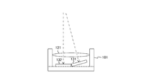
- FIG. 14 is a top view showing a configuration example of the optical system according to the second embodiment.
- the optical system of the second embodiment is different from that of the first embodiment in that the lens barrel 102 and the standard lens 122 are not provided.
- the standard lens 121 and the image sensors 131 and 132 are provided in the lens barrel 101.
- the standard lens 121 is shared by the image sensors 131 and 132, and both of the image sensors receive light from the standard lens 121.
- the standard lens 121 is arranged so that its lens surface is parallel to the bottom surface of the lens barrel 101, and the image sensors 131 and 132 are arranged so that the light receiving surface is inclined with respect to the bottom surface of the lens barrel 101.
- the standard lens 121 and the image sensors 131 and 132 are arranged in the same camera module 110, they may be arranged in separate modules and units.
- the standard lens 121 may be disposed in the lens unit, and the imaging elements 131 and 132 may be disposed in the camera module or the camera unit.
- the number of parts of the optical system can be reduced as compared with the configuration in which two standard lenses are provided.
- both the image sensors 131 and 132 are inclined with respect to the bottom surface of the lens barrel 101.
- the electronic device 100 according to the first modification of the first embodiment is different from the first embodiment in that the increase in the number of parts of the optical system and the displacement are suppressed.
- FIG. 15 is a top view illustrating a configuration example of the optical system according to the modification of the second embodiment.
- the optical system of this modification is different from the second embodiment in that the image sensor 132 is arranged so that the light receiving surface of the image sensor 132 is parallel to the bottom surface of the lens barrel 101.
- the image sensor 132 arranged in parallel to the bottom surface of the lens barrel 101 can also be used as a main camera for capturing a moving image or a still image. For example, when capturing a moving image or a still image without ranging, only the image sensor 132 may be used.
- the camera module 110 and the arithmetic processing unit 150 are arranged in the same device (electronic device 100). However, they can be distributed and arranged in separate devices.
- the system of the third embodiment is different from the first embodiment in that the camera module is arranged in a device different from the arithmetic processing unit.
- the information processing system is an example of an imaging system described in the claims.
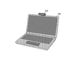
- FIG. 16 is an example of an external view of an information processing system according to the third embodiment.
- This information processing system includes a camera unit 200 and an information processing apparatus 300.
- the information processing apparatus 300 for example, a notebook or desktop personal computer is assumed.
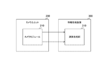
- FIG. 17 is a block diagram illustrating a configuration example of the information processing system according to the third embodiment.
- a camera module 210 is disposed in the camera unit 200, and an arithmetic processing unit 310 is disposed in the information processing apparatus 300.
- FIG. 18 is a block diagram illustrating a configuration example of the camera module 210 according to the third embodiment.
- the camera module 210 includes standard lenses 221 and 222, image sensors 231 and 232, and a synchronization control unit 240.
- the configurations of the standard lenses 221 and 222, the image sensors 231 and 232, and the synchronization control unit 240 are the same as those of the standard lenses 121 and 122, the image sensors 131 and 132, and the synchronization control unit 140 in the first embodiment. It is.
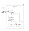
- FIG. 19 is a block diagram illustrating a configuration example of the arithmetic processing unit 310 according to the third embodiment.
- the arithmetic processing unit 310 includes a feature point extraction unit 311, an image shift amount acquisition unit 312, a distance measurement unit 313, and a UI processing unit 314.
- the configuration of the feature point extraction unit 311, the image shift amount acquisition unit 312, the distance measurement unit 313, and the UI processing unit 314 includes the feature point extraction unit 151, the image shift amount acquisition unit 152, and the distance measurement in the first embodiment. This is the same as the unit 153 and the UI processing unit 154.
- the functions of the feature point extraction unit 311, the image shift amount acquisition unit 312, the distance measurement unit 313, and the UI processing unit 314 are realized by a program, for example. As a result, even if the information processing apparatus 300 does not include the pair of imaging elements 131 and 132 whose optical axes intersect with each other, if the camera unit 200 is attached and a program is installed, the distance can be measured with high accuracy. Become. Note that at least some of the feature point extraction unit 311, the image shift amount acquisition unit 312, the distance measurement unit 313, and the UI processing unit 314 may be realized by a circuit instead of a program.
- the camera module 210 is arranged in the camera unit 200 outside the information processing apparatus 300, information that does not include a pair of imaging elements whose optical axes intersect with each other. Ranging accuracy can be improved in the processing device 300. In addition, since the baseline length can be shortened without lowering the distance measurement accuracy, the size of the camera unit 200 can be reduced.
- the information processing apparatus 300 performs the process of measuring the distance. However, the processing load on the information processing apparatus 300 increases by that process.
- the information processing system according to the modification of the third embodiment is different from the third embodiment in that the processing load on the information processing apparatus 300 is reduced.
- FIG. 20 is a block diagram illustrating a configuration example of an information processing system according to a modification of the third embodiment.
- the camera unit 200 of this modification is different from the third embodiment in that it further includes a feature point extraction unit 251, an image shift amount acquisition unit 252, and a distance measurement unit 253.
- the configuration of the feature point extraction unit 251, the image shift amount acquisition unit 252 and the distance measurement unit 253 is the same as that of the feature point extraction unit 151, the image shift amount acquisition unit 152 and the distance measurement unit 153 in the first embodiment. is there.
- the information processing apparatus 300 according to the modified example is different from the third embodiment in that the feature point extraction unit 311, the image shift amount acquisition unit 312, and the distance measurement unit 313 are not provided.
- the information processing apparatus 300 since the feature point extraction unit 251, the image shift amount acquisition unit 252, and the distance measurement unit 253 are arranged on the camera unit 200 side, the information processing apparatus 300 does not need to perform a process of measuring the distance. Thereby, the processing load of the information processing apparatus 300 can be reduced.
- the feature point extraction unit 251, the image shift amount acquisition unit 252, and the distance measurement unit 253 are arranged on the camera unit 200 side, only a part of them is arranged in the camera unit 200, and the rest is processed as information processing.
- positioned in the apparatus 300 may be sufficient.
- the information processing apparatus 300 measures the distance.
- the processing load can be reduced.
- the processing procedure described in the above embodiment may be regarded as a method having a series of these procedures, and a program for causing a computer to execute these series of procedures or a recording medium storing the program. You may catch it.
- a recording medium for example, a CD (Compact Disc), an MD (MiniDisc), a DVD (Digital Versatile Disc), a memory card, a Blu-ray disc (Blu-ray (registered trademark) Disc), or the like can be used.
- this technique can also take the following structures.
- a pair of imaging elements whose axes perpendicular to the respective light receiving surfaces intersect each other;
- An imaging apparatus comprising: a distance measuring unit that measures a distance to an object based on parallax obtained from a pair of images captured by the pair of imaging elements.
- the imaging apparatus according to (1) further including an imaging lens that collects light and guides the light to the pair of imaging elements.
- a distance measuring unit that measures a distance to an object based on a parallax obtained from a pair of images captured by the pair of imaging elements;
- An imaging system comprising: a processing unit that performs processing for recognizing the shape of the object based on the measured distance and the pair of images.
- DESCRIPTION OF SYMBOLS 100 Electronic device 101, 102 Lens barrel 110, 210 Camera module 121, 122, 221, 222 Standard lens 123, 124 Wide angle lens 131, 132, 231, 232 Image sensor 140, 240 Synchronization control unit 150, 310 Arithmetic processing unit 151, 251, 311 Feature point extraction unit 152, 252, 312 Image shift amount acquisition unit 153, 253, 313 Distance measurement unit 154, 314 UI processing unit 155 Distortion amount acquisition unit 200 Camera unit 300 Information processing apparatus
Landscapes
- Engineering & Computer Science (AREA)
- Physics & Mathematics (AREA)
- General Physics & Mathematics (AREA)
- Multimedia (AREA)
- Signal Processing (AREA)
- General Engineering & Computer Science (AREA)
- Theoretical Computer Science (AREA)
- Radar, Positioning & Navigation (AREA)
- Remote Sensing (AREA)
- Electromagnetism (AREA)
- Human Computer Interaction (AREA)
- Measurement Of Optical Distance (AREA)
- Studio Devices (AREA)
Abstract
対象物までの距離を測定する装置において装置の小型化と測距精度の向上とを両立する。 撮像装置は、一対の撮像素子と、測距部とを具備する。この撮像装置における一対の撮像素子について、それぞれの受光面に垂直な軸は互いに交差する。また、一対の撮像素子と測距部とを具備する撮像装置において、測距部は、それぞれの受光面に垂直な軸は互いに交差する一対の撮像素子により撮像された一対の画像から得られた視差に基づいて対象物までの距離を測定する。
Description
本技術は、撮像装置、および、撮像システムに関する。詳しくは、対象物までの距離を測定する撮像装置、および、撮像システムに関する。
従来より、ステレオ画像の撮像などの目的で、一対の撮像素子を設けた2眼の撮像装置が用いられている。この2眼の撮像装置では、一対の撮像素子の一方で得られた像と他方で得られた像との間に視差により像ずれ量が生じる。この像ずれ量は、対象物までの距離に応じて変化することが知られているため、この像ずれ量から距離を算出することができる。例えば、それぞれの受光面に垂直な光軸が平行になるように一対の撮像素子を配置し、所定の関係式を使用して像ずれ量Zから対象物までの距離Dを測定する撮像装置が提案されている(例えば、特許文献1参照。)。この関係式において、像ずれ量Zは、一対の撮像素子の間の間隔(以下、「基線長」と称する。)Bが大きいほど大きくなり、また、距離Dが遠いほど小さくなる。
しかしながら、上述の従来技術では、距離Dが遠くなるほど像ずれ量Zが小さくなり、測距精度が低下するおそれがある。前述したように基線長Bを大きくすれば、像ずれ量Zを相対的に大きくして測距精度を向上させることができるが、基線長Bを大きくすると装置が大型化するおそれがある。このように、装置の小型化と測距精度の向上とを両立することが困難である。
本技術はこのような状況に鑑みて生み出されたものであり、対象物までの距離を測定する装置において装置の小型化と測距精度の向上とを両立することを目的とする。
本技術は、上述の問題点を解消するためになされたものであり、その第1の側面は、それぞれの受光面に垂直な軸が互いに交差する一対の撮像素子と、上記一対の撮像素子により撮像された一対の画像から得られた視差に基づいて対象物までの距離を測定する測距部とを具備する撮像装置である。これにより、一対の画像から得られた視差に基づいて距離が測定されるという作用をもたらす。
また、この第1の側面において、光を集光して上記一対の撮像素子に導く撮像レンズをさらに具備してもよい。これにより、1枚の撮像レンズにより集光された光を受光する一対の撮像レンズにより、一対の画像が撮像されるという作用をもたらす。
また、この第1の側面において、一対の撮像レンズをさらに具備し、上記一対の撮像レンズの一方は、光を集光して上記一対の撮像素子の一方に導き、上記一対の撮像レンズの他方は、光を集光して上記一対の撮像素子の他方に導いてもよい。これにより、一対の撮像レンズにより集光された光を受光する一対の撮像レンズにより、一対の画像が撮像されるという作用をもたらす。
また、この第1の側面において、鏡筒をさらに具備し、上記一対の撮像素子の一方の上記受光面は、上記鏡筒の底面に平行であってもよい。これにより、一方の受光面が、鏡筒の底面に平行な一対の撮像素子により画像が撮像されるという作用をもたらす。
また、この第1の側面において、上記測距部は、上記一対の画像の一方と他方との間の像ずれ量から上記距離を測定してもよい。これにより、像ずれ量から距離が測定されるという作用をもたらす。
また、この第1の側面において、上記測距部は、上記一対の画像の一方の他方に対する歪み量から上記距離を測定してもよい。これにより、一対の画像の一方の他方に対する歪み量から距離が測定されるという作用をもたらす。
また、本技術の第2の側面は、それぞれの受光面に垂直な軸が互いに交差する一対の撮像素子と、上記一対の撮像素子により撮像された一対の画像から得られた視差に基づいて対象物までの距離を測定する測距部と、上記測定された距離と上記一対の画像とに基づいて上記対象物の形状を認識する処理を行う処理部とを具備する撮像システムである。これにより、一対の画像から得られた視差に基づいて距離が測定されるという作用をもたらす。
本技術によれば、対象物までの距離を測定する装置において装置の小型化と測距精度の向上とを両立することができるという優れた効果を奏し得る。なお、ここに記載された効果は必ずしも限定されるものではなく、本開示中に記載されたいずれかの効果であってもよい。
以下、本技術を実施するための形態(以下、実施の形態と称する)について説明する。説明は以下の順序により行う。
1.第1の実施の形態(光軸が互いに交差する一対の撮像素子を設ける例)
2.第2の実施の形態(レンズが1つの光学系に光軸が互いに交差する一対の撮像素子を設ける例)
3.第3の実施の形態(光軸が互いに交差する一対の撮像素子を設けたカメラモジュールを装置の外部に配置する例)
1.第1の実施の形態(光軸が互いに交差する一対の撮像素子を設ける例)
2.第2の実施の形態(レンズが1つの光学系に光軸が互いに交差する一対の撮像素子を設ける例)
3.第3の実施の形態(光軸が互いに交差する一対の撮像素子を設けたカメラモジュールを装置の外部に配置する例)
<1.第1の実施の形態>
[電子装置の構成例]
図1は、第1の実施の形態における電子装置100の外観図の一例である。この電子装置100としては、例えば、スマートフォンやタブレット端末などの、撮像機能を持つモバイル機器が想定される。電子装置100のディスプレイが設けられた正面には、一定の間隔を空けて標準レンズ121および122が配置される。なお、電子装置100の正面でなく、ディスプレイの設けられていない背面に標準レンズ121および122を配置してもよい。
[電子装置の構成例]
図1は、第1の実施の形態における電子装置100の外観図の一例である。この電子装置100としては、例えば、スマートフォンやタブレット端末などの、撮像機能を持つモバイル機器が想定される。電子装置100のディスプレイが設けられた正面には、一定の間隔を空けて標準レンズ121および122が配置される。なお、電子装置100の正面でなく、ディスプレイの設けられていない背面に標準レンズ121および122を配置してもよい。
標準レンズ121および122は、光を集光して撮像素子に導くレンズである。これらのレンズの画角は、一定値(例えば、60度)以下である。
なお、標準レンズ121および122は、特許請求の範囲に記載の撮像レンズの一例である。また、電子装置100は、特許請求の範囲に記載の撮像装置の一例である。
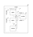
図2は、第1の実施の形態における電子装置100の一構成例を示すブロック図である。この電子装置100は、カメラモジュール110および演算処理部150を備える。このカメラモジュール110は、標準レンズ121および122と、撮像素子131および132と、同期制御部140とを備える。
撮像素子131は、標準レンズ121からの光を光電変換して画像データを撮像するものである。撮像素子132は、標準レンズ122からの光を光電変換して画像データを撮像するものである。これらの撮像素子は、受光面に二次元格子状に配列された複数の光電変換素子を含む。また、これらの撮像素子131および132は、それぞれの受光面に垂直な光軸が互いに交差するように配置される。ただし、図2においては、記載の便宜上、実装と異なり、それぞれの光軸を平行としている。
ここで、標準レンズ121および撮像素子131は、電子装置100の背面から見て、右側に配置され、標準レンズ122および撮像素子132は左側に配置される。撮像素子131は、撮像した画像データを右側画像データとして演算処理部150に信号線118を介して供給する。一方、撮像素子132は、撮像した画像データを左側画像データとして演算処理部150に信号線119を介して供給する。これらの右側画像データおよび左側画像データのそれぞれは、二次元格子状に配列された複数の画素を含む。
同期制御部140は、撮像素子131および132の撮像動作を同期させるものである。例えば、ジェスチャ認識を行うためのアプリケーションが実行されると、同期制御部140は、一定の周波数の垂直同期信号の生成を開始する。同期制御部140は、その垂直同期信号を撮像素子131および132に信号線148および149を介して送信する。そして、撮像素子131および132は、その共通の垂直同期信号に同期して撮像を行う。
なお、同期制御部140をカメラモジュール110の内部に配置しているが、その外部に配置してもよい。また、静止した物体の撮像しか想定されない場合には、同期制御部140を設けない構成とすることもできる。なお、標準レンズ121および122と、撮像素子131および132とを同一のカメラモジュールに配置しているが、これらを複数のモジュールに分散して配置してもよい。例えば、標準レンズ121および撮像素子131を右側カメラモジュールに配置し、標準レンズ122および撮像素子132を左側カメラモジュールに配置してもよい。
演算処理部150は、左側画像データおよび右側画像データに基づいて所定の演算処理を行うものである。この演算処理は、左側画像データと右側画像データとの像ずれ量から距離を測定する処理を含む。
なお、電子装置100は、二次元格子状に光電変換素子が配列された撮像素子131および132で得られたデータに基づいて測距しているが、直線状に光電変換素子が配置された一対の撮像素子で得られたデータに基づいて測距してもよい。このように光電変換素子が直線状に配置された撮像素子は、リニアイメージセンサとも呼ばれる。一対のリニアイメージセンサを設ける場合には、撮像素子131および132を設けなくてもよいし、それらをリニアイメージセンサと別途に設けてもよい。
[演算処理部の構成例]
図3は、第1の実施の形態における演算処理部150の一構成例を示すブロック図である。この演算処理部150は、特徴点抽出部151、像ずれ量取得部152、測距部153およびUI(User Interface)処理部154を備える。
図3は、第1の実施の形態における演算処理部150の一構成例を示すブロック図である。この演算処理部150は、特徴点抽出部151、像ずれ量取得部152、測距部153およびUI(User Interface)処理部154を備える。
特徴点抽出部151は、左側画像データおよび右側画像データのそれぞれにおいて、特徴点を抽出するものである。ここで、特徴点は、エッジの交点(コーナー)など、色彩や輝度が大きく変化する部分を意味する。
特徴点を抽出するアルゴリズムとして、例えば、「金澤 靖、他1名、"解説 コンピュータビジョンのための画像の特徴点の抽出"、電子情報通信学会誌Vol.87,No.12,2004」に記載のものが用いられる。このアルゴリズムでは、一階微分とガウス平滑化の組合せによりHarris作用素が特徴点として抽出される。または、輝度値の各方向の分散を直接に評価するMoravec作用素が特徴点として抽出される。あるいは、円形マスクを用いてマスク中の任意の閾値以上の画素数をカウントするSUSAN(Smallest Univalue Segment Assimilating Nucleus)オペレータにより特徴点が抽出される。なお、特徴点を抽出することができるものであれば、上述とは異なるアルゴリズムを用いてもよい。
特徴点抽出部151は、左側画像データおよび右側画像データのそれぞれについて、画像内の特徴点の座標と特徴点を識別する識別情報とを特徴点ごとに含む特徴点情報を生成し、像ずれ量取得部152およびUI処理部154に供給する。
像ずれ量取得部152は、特徴点情報に基づいて、左側画像データと右側画像データとの像ずれ量を取得するものである。この像ずれ量取得部152は、例えば、左側画像データにおける特徴点の少なくとも1つについて、その特徴点に対応する右側画像データ内の特徴点を求める。
対応する特徴点を求める(言い換えれば、マッチングをする)際に、像ずれ量取得部152は、例えば、特徴点を中心とする一定形状(円など)の領域の特徴量を特徴点ごとに求め、それらの特徴量の類似度が一定値より高い特徴点同士を対応付ける。特徴量として、例えば、輝度勾配の方向を示すベクトルが求められる。なお、像ずれ量取得部152は、この方式以外のアルゴリズムにより、マッチングを行ってもよい。
そして、像ずれ量取得部152は、対応する特徴点のペアごとに、対応する特徴点の間の距離(ユークリッド距離など)を像ずれ量Zとして算出し、測距部153に供給する。
測距部153は、特徴点ごとに、像ずれ量Zから距離Dを測定するものである。測距部153は、測定した距離DをUI処理部154に供給する。なお、像ずれ量取得部152は、特徴点についてのみ距離Dを算出しているが、画素の全てについて距離Dを算出してもよい。
UI処理部154は、特徴点毎の座標と距離Dとに基づいてユーザインターフェースに関する入力処理を行うものである。例えば、UI処理部154は、特徴点毎の座標と距離Dとから人体の形状を認識し、その形状、または、その形状の時間的変化をジェスチャとして検知する。UI処理部154は、検知したジェスチャに対応する入力処理を実行する。例えば、「右手を左右に振る」というジェスチャについて、画面を移動(スワイプ)させるというスワイプ処理を予め対応付けておき、UI処理部154は、そのジェスチャの認識時にスワイプ処理を行う。なお、UI処理部154は、特許請求の範囲に記載の処理部の一例である。
なお、演算処理部150は、マッチングした特徴点から像ずれ量Zを求めているが、別の手法により像ずれ量Zを求めてもよい。像ずれ量取得部152は、例えば、フーリエ変換を用いる位相限定相関(POC: Phase Only Correlation)法を用いて、像ずれ量Zを求めてもよい。このPOC法を用いる場合には、測距において特徴点の抽出が不要となる。
また、演算処理部150は、距離DをUI処理に用いているが、他の処理に用いてもよい。例えば、AF(Auto Focus)処理や、デプスマップの生成処理に用いてもよい。
[光学系の構成例]
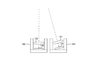
図4は、第1の実施の形態における光学系の一構成例を示す上面図である。この光学系は、標準レンズ121および122と、撮像素子131および132と、鏡筒101および102を備える。鏡筒101の中に、標準レンズ121および撮像素子131が配置され、鏡筒102の中に、標準レンズ122および撮像素子132が配置される。同図は、この光学系を、電子装置100のディスプレイの面に平行な所定の方向から見た上面図である。
図4は、第1の実施の形態における光学系の一構成例を示す上面図である。この光学系は、標準レンズ121および122と、撮像素子131および132と、鏡筒101および102を備える。鏡筒101の中に、標準レンズ121および撮像素子131が配置され、鏡筒102の中に、標準レンズ122および撮像素子132が配置される。同図は、この光学系を、電子装置100のディスプレイの面に平行な所定の方向から見た上面図である。
標準レンズ121は、そのレンズ面が撮像素子131の受光面と略平行になるように配置される。また、標準レンズ122は、そのレンズ面が撮像素子132の受光面と略平行になるように配置される。
また、撮像素子131および132は、それぞれの受光面に垂直な光軸が互いに交差するように配置される。例えば、鏡筒101の底面と撮像素子131の受光面とが所定の角度をなすように撮像素子131が配置され、鏡筒102の底面と撮像素子132の受光面とが所定の角度をなすように撮像素子132が配置される。
また、撮像素子131および132のそれぞれの代表点(例えば、受光面の中心)の位置は、ディスプレイの表面に垂直な方向(以下、「奥行き方向」と称する。)において等位であることが望ましい。
また、奥行き方向に垂直な方向における、撮像素子131および132のそれぞれの代表点の距離を基線長B_crossとする。この基線長B_crossの間隔で配置された撮像素子131および132のそれぞれから、ある対象物500を見たときの角度は、左側の撮像素子132と右側の撮像素子131との間で異なり、この角度の差は視差と呼ばれる。この視差により像ずれ量Zが生じる。この像ずれ量Z(視差)は、標準レンズ121および122から奥行き方向における所定の対象物500までの距離Dに応じて変化する。このため、像ずれ量Zから距離Dを求めることができる。一般に、基線長Bの一対の撮像素子から得られた像ずれ量Zと距離Dとの間には、次の式に示す関係式が成立する。
D=f×B/Z ・・・式1
上式において、fは、標準レンズ121および122の焦点距離を示す。また、距離D、焦点距離fおよび基線長Bの単位は、例えば、メートル(m)である。
D=f×B/Z ・・・式1
上式において、fは、標準レンズ121および122の焦点距離を示す。また、距離D、焦点距離fおよび基線長Bの単位は、例えば、メートル(m)である。
図5は、第1の実施の形態におけるレンズの傾きと視差との間の関係について説明するための図である。同図におけるaは、それぞれの光軸が平行になるように撮像素子131および132を配置した比較例の光学系の上面図である。この構成で、奥行き方向に垂直な方向における、撮像素子131の中心座標X1と撮像素子132の中心座標X2との間の距離を基線長B_paraとする。この基線長B_paraは、基線長B_crossより長いものとする。また、ある対象物500と撮像素子131の中心とを結ぶ直線に対して受光面のなす角度(言い換えれば、撮像素子131から対象物を見た際の角度)をR_paraとする。
図5におけるbは、撮像素子131を傾斜させた場合の光学系の上面図である。奥行き方向に垂直な方向に対して、撮像素子131の受光面を傾斜角R_tiltだけ傾斜させた構成を想定する。そして、傾斜させた撮像素子131を撮像素子132の方へ平行移動し、ある位置X3で撮像素子131から対象物500を見た角度がR_paraになったものとする。この位置X3では、撮像素子131から対象物500を見た角度が傾斜前と同じであるため、撮像素子131には、同図におけるaと同じ像が結像される。
図6は、第1の実施の形態における視差から距離を算出する方法について説明するための図である。図5におけるbの状態で撮像素子132をさらに撮像素子131と逆方向に傾斜角R_tiltだけ傾斜させ、撮像素子131と同じ距離だけ逆方向に平行移動させた構成を想定する。この位置X4では、撮像素子132から対象物500を見た角度が傾斜前と同じになるため、撮像素子132には、図5の傾斜前と同じ像が結像される。この傾斜後のX3とX4との間の距離を基線長B_crossとする。この基線長B_crossが基線長B_paraよりも短くなるにも関わらず、撮像素子131および132には傾斜前と同じ像が結像されるため、像ずれ量Zは傾斜前と同じである。像ずれ量Zが同一であるため、撮像素子131および132を傾斜させない場合と、それらを傾斜させた場合とで測距精度は同等である。
このように、撮像素子131および132を傾斜させて光軸を交差させると、測距精度を低下させずに、基線長を短くすることができる。これにより、電子装置100を小型化することができる。また、仮に、基線長B_crossのままで光軸が平行になるように撮像素子131および132を配置すると、像ずれ量Zが小さくなり測距精度が低下する。すなわち、撮像素子131および132の光軸を交差させると、光軸が平行な場合と比較して、基線長を変えずに像ずれ量ZをB_para/B_cross倍にすることができる。これにより、測距精度を向上させることができる。このように、電子装置100の小型化と、測距精度の向上とを両立することができる。
基線長B_paraは、傾斜角R_tiltおよび基線長B_crossから三角関数を用いて算出することができる。測距部153は、予め算出しておいた基線長B_paraを式1に適用した次の式を用いて距離Dを算出する。
D=f×B_para/Z ・・・式2
D=f×B_para/Z ・・・式2
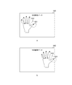
図7は、第1の実施の形態における左側画像データおよび右側画像データの一例を示す図である。同図におけるaは、左側画像データ510の一例であり、同図におけるbは右側画像データ520の一例である。これらの画像データにおける黒丸は、特徴点を示す。
特徴点抽出部151は、左側画像データ510において、特徴点511などを抽出し、右側画像データ520において特徴点521などを抽出する。そして、像ずれ量取得部152は、特徴点のマッチングを行う。例えば、左側画像データの特徴点511について、右側画像データの特徴点521が対応付けられたものとする。像ずれ量取得部152は、これらの対応する一対の特徴点の間の距離を像ずれ量Zとして取得する。
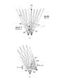
図8は、第1の実施の形態における距離誤差について説明するための図である。同図におけるaは、光軸を平行にして一対の撮像素子を配置した比較例における距離誤差の一例を示す図である。同図において、放射線状の実線は、撮像素子に入射される光の光路を示す。それぞれの光路と、受光面とのなす角度は、互いにdRずつ異なるものとする。また、白丸501および502は、測距対象の物体を示す。白丸501を測距する際に、撮像素子の一方から見た際の角度±dR程度の視差の変化では、像ずれ量Zに変化がほとんど生じないとすると、この±dRに対応する距離誤差が生じる。例えば、角度+dRに対応する黒丸503から角度-dRに対応する黒丸504までの距離誤差dD_para1が生じる。また、白丸502についても、距離誤差dD_para2が生じる。
図8におけるbは、光軸が交差する撮像素子131および132を配置した光学系における距離誤差の一例を示す図である。白丸501および502の位置は、同図におけるaと同じであるものとする。光軸を交差させると、同図におけるbに例示するように、角度+dRに対応する黒丸503と角度-dRに対応する黒丸504との距離が近くなるため、白丸501を測距時の距離誤差はdD_para1からdD_cross1に低下する。また、白丸502を測距時の距離誤差もdD_para2からdD_cross2に低下する。このように、光軸を交差させることで、交差させない構成と比較して測距精度が向上する。
[電子装置の動作例]
図9は、第1の実施の形態における電子装置100の動作の一例を示すフローチャートである。この動作は、例えば、ユーザインターフェース処理を行うための所定のアプリケーションが実行されたときに開始する。
図9は、第1の実施の形態における電子装置100の動作の一例を示すフローチャートである。この動作は、例えば、ユーザインターフェース処理を行うための所定のアプリケーションが実行されたときに開始する。
電子装置100は、左側画像データおよび右側画像データを撮像し(ステップS901)、それらの画像データにおいて特徴点の抽出を行う(ステップS902)。電子装置100は、特徴点のマッチングを行い、対応する一対の特徴点の間の距離を像ずれ量Zとして取得する(ステップS903)。そして、電子装置100は、像ずれ量Zから式2を用いて距離Dを測定する(ステップS904)。電子装置100は、求めた距離Dと、特徴点の座標とに基づいてユーザインターフェース処理を行う(ステップS905)。ステップS905の後に、電子装置100は、ステップS901以降を繰り返し実行する。
このように、本技術の第1の実施の形態によれば、光軸が互いに交差するように撮像素子131および132を配置したため、光軸が平行になるように配置した構成と比較して像ずれ量を大きくすることができる。これにより、測距精度を向上させることができる。また、測距精度を低下させずに、基線長を小さくすることができるため、装置を小型化することができる。
[第1の変形例]
上述の第1の実施の形態では、鏡筒101および102の底面に対して、撮像素子131および132の両方を傾斜させていた。しかし、傾斜させて配置するには、鏡筒と撮像素子との間に、傾斜した撮像素子を支持する支持部材などを設ける必要があり、部品点数が増大するおそれがある。また、傾斜させて配置する際に、位置ずれが生じるおそれがある。この第1の実施の形態の第1の変形例の電子装置100は、光学系の部品点数の増大や位置ずれを抑制する点において第1の実施の形態と異なる。
上述の第1の実施の形態では、鏡筒101および102の底面に対して、撮像素子131および132の両方を傾斜させていた。しかし、傾斜させて配置するには、鏡筒と撮像素子との間に、傾斜した撮像素子を支持する支持部材などを設ける必要があり、部品点数が増大するおそれがある。また、傾斜させて配置する際に、位置ずれが生じるおそれがある。この第1の実施の形態の第1の変形例の電子装置100は、光学系の部品点数の増大や位置ずれを抑制する点において第1の実施の形態と異なる。
図10は、第1の実施の形態の第1の変形例における光学系の一構成例を示す上面図である。この第1の変形例の光学系は、標準レンズ122のレンズ面と撮像素子132の受光面とが、鏡筒102の底面に平行になるように、標準レンズ122および撮像素子132が配置される点において第1の実施の形態と異なる。これにより、撮像素子132については支持部材が不要となるため、光学系の部品点数の増大を抑制することができる。また、撮像素子132の位置ずれの発生を抑制することができる。さらに、鏡筒102の底面に平行に配置した撮像素子132を、動画や静止画を撮像する際のメインカメラに兼用することができる。例えば、測距せずに動画や静止画を撮像する際には、撮像素子132のみを用いればよい。
このように、本技術の第1の実施の形態の第1の変形例によれば、一対の撮像素子の一方の受光面を鏡筒102の底面に平行になるように配置したため、光学系の部品点数の増大や位置ずれを抑制することができる。
[第2の変形例]
上述の第1の実施の形態では、撮像素子131および132を傾斜させて、像ずれ量Zを相対的に大きくしていたが、距離Dが遠いと、像ずれ量Zを増大させても測距精度が不十分になるおそれがある。ここで、画角が比較的大きな広角レンズでは、画像データの周辺部分などで、実際の形状と比較して像が歪む現象(歪曲収差)が生じることが知られている。この歪曲収差による同一物体についての歪み量は、左側画像データと右側画像データとで異なることがある。これは、立体的な物体を異なる角度から見ると、その形状が変化するためである。この歪み量は、物体までの距離が近いほど大きくなるため、歪み量から距離を測定することができる。像ずれ量Zがほとんどなくとも、物体が立体的であれば、視差により左側画像データと右側画像データとで歪み量に差が生じることがあるため、この歪み量(視差)を考慮することにより、測距精度を向上させることができる。この第1の実施の形態の第2の変形例の電子装置100は、歪み量を用いて測距精度を向上させた点において第1の実施の形態と異なる。
上述の第1の実施の形態では、撮像素子131および132を傾斜させて、像ずれ量Zを相対的に大きくしていたが、距離Dが遠いと、像ずれ量Zを増大させても測距精度が不十分になるおそれがある。ここで、画角が比較的大きな広角レンズでは、画像データの周辺部分などで、実際の形状と比較して像が歪む現象(歪曲収差)が生じることが知られている。この歪曲収差による同一物体についての歪み量は、左側画像データと右側画像データとで異なることがある。これは、立体的な物体を異なる角度から見ると、その形状が変化するためである。この歪み量は、物体までの距離が近いほど大きくなるため、歪み量から距離を測定することができる。像ずれ量Zがほとんどなくとも、物体が立体的であれば、視差により左側画像データと右側画像データとで歪み量に差が生じることがあるため、この歪み量(視差)を考慮することにより、測距精度を向上させることができる。この第1の実施の形態の第2の変形例の電子装置100は、歪み量を用いて測距精度を向上させた点において第1の実施の形態と異なる。
図11は、第1の実施の形態の第2の変形例における電子装置100の一構成例を示すブロック図である。この第2の変形例の電子装置100は、標準レンズ121および122の代わりに広角レンズ123および124を備える点において第1の実施の形態と異なる。
広角レンズ123および124は、画角が一定値(例えば、60度)より大きなレンズである。
図12は、第1の実施の形態の第2の変形例における演算処理部150の一構成例を示すブロック図である。この第2の変形例の演算処理部150は、歪み量取得部155をさらに備える点において第1の実施の形態と異なる。
歪み量取得部155は、左側画像データおよび右側画像データの一方に対する他方の歪み量を取得するものである。この歪み量取得部155は、像ずれ量取得部152から、特徴点の対応関係を含む特徴点情報を受け取り、撮像素子131および132から左側画像データおよび右側画像データを受け取る。そして、歪み量取得部155は、対応する一対の特徴点の一方を中心とする一定形状(円など)の領域と、他方を中心とする一定形状の領域との差を歪み量Sとして求める。領域同士の差は、例えば、対応する画素値の差分の絶対値の総和(SAD:Sum of Absolute Difference)や、画素値の差分の二乗和(SSD:um of Squared Difference)により表される。歪み量取得部155は、特徴点ごとに歪み量Sを求め、測距部153に供給する。
なお、特徴点のマッチングは、歪み量取得部155で行い、像ずれ量取得部152に特徴点の対応関係を通知してもよい。または、マッチングを行う回路やプログラムを歪み量取得部155または像ずれ量取得部152から分離し、その回路等を歪み量取得部155および像ずれ量取得部152で共有してもよい。
また、第2の変形例の測距部153は、像ずれ量Zと歪み量Sとから距離Dを測定する。測距部153は、例えば、歪み量Sが大きいほど近い距離Dsを出力する所定の関数により距離Dsを求め、像ずれ量Zから式2により距離をDzとして求める。そして、距離Dsと距離Dzとの差異が一定の許容値を超える場合には、距離Dsを選択して距離DとしてUI処理部154に供給する。一方、距離Dsと距離Dzとの差異が許容値以内である場合には、測距部153は、それらの平均や重み付け加算値などを距離DとしてUI処理部154に供給する。
なお、測距部153は、像ずれ量Zと歪み量Sとから距離Dを測定しているが、歪み量Sのみから距離Dを測定することもできる。
図13は、第1の実施の形態の第2の変形例における左側画像データおよび右側画像データの一例を示す図である。同図におけるaは、第2の変形例における左側画像データ530の一例であり、同図におけるbは、第2の変形例における右側画像データ540の一例である。これらの画像データにおける黒丸は、特徴点を示す。同図におけるaおよびbに例示するように、一対の画像データのそれぞれについて歪みが生じており、その歪み量は、それぞれの画像データにおいて異なる。
特徴点抽出部151は、左側画像データ530において、特徴点531などを抽出し、右側画像データ540において特徴点541などを抽出する。そして、像ずれ量取得部152は、特徴点のマッチングを行う。例えば、左側画像データの特徴点531について、右側画像データの特徴点541が対応付けられたものとする。
また、歪み量取得部155は、特徴点531の周囲の領域532と、対応する特徴点541の周囲の領域542との間の差を歪み量Sとして取得する。この歪み量Sから距離が求められる。
このように、本技術の第1の実施の形態の第2の変形例によれば、電子装置100は、一対の画像の一方に対する他方の歪み量から距離を測定するため、測距精度を向上させることができる。
<2.第2の実施の形態>
上述の第1の実施の形態では、撮像素子131および132のそれぞれに、標準レンズを設ける必要があったため、一眼の構成と比較して光学系の部品点数が増大してしまう。この第2の実施の形態の電子装置100は、光学系の部品点数の増大を抑制する点において第1の実施の形態と異なる。
上述の第1の実施の形態では、撮像素子131および132のそれぞれに、標準レンズを設ける必要があったため、一眼の構成と比較して光学系の部品点数が増大してしまう。この第2の実施の形態の電子装置100は、光学系の部品点数の増大を抑制する点において第1の実施の形態と異なる。
図14は、第2の実施の形態における光学系の一構成例を示す上面図である。この第2の実施の形態の光学系は、鏡筒102および標準レンズ122を設けない点において第1の実施の形態と異なる。
また、第2の実施の形態では、鏡筒101内に標準レンズ121と撮像素子131および132とが設けられる。そして、標準レンズ121は、撮像素子131および132に共有され、それらの撮像素子は、いずれも標準レンズ121からの光を受光する。標準レンズ121は、そのレンズ面が鏡筒101の底面と平行になるように配置され、撮像素子131および132は、その受光面が鏡筒101の底面に対して傾斜するように配置される。
なお、標準レンズ121と撮像素子131および132とを同一のカメラモジュール110に配置しているが、別々のモジュールやユニットに配置してもよい。例えば、標準レンズ121をレンズユニットに配置し、撮像素子131および132をカメラモジュールやカメラユニットに配置してもよい。
このように、本技術の第2の実施の形態によれば、標準レンズを1枚のみとしたため、標準レンズを2枚設ける構成と比較して光学系の部品点数を削減することができる。
[変形例]
上述の第2の実施の形態では、鏡筒101の底面に対して、撮像素子131および132の両方を傾斜させていた。しかし、傾斜させて配置するには、鏡筒101と撮像素子131等との間に支持部材などを設ける必要があり、部品点数が増大するおそれがある。また、傾斜させて配置する際に、位置ずれが生じるおそれがある。この第1の実施の形態の第1の変形例の電子装置100は、光学系の部品点数の増大や位置ずれを抑制する点において第1の実施の形態と異なる。
上述の第2の実施の形態では、鏡筒101の底面に対して、撮像素子131および132の両方を傾斜させていた。しかし、傾斜させて配置するには、鏡筒101と撮像素子131等との間に支持部材などを設ける必要があり、部品点数が増大するおそれがある。また、傾斜させて配置する際に、位置ずれが生じるおそれがある。この第1の実施の形態の第1の変形例の電子装置100は、光学系の部品点数の増大や位置ずれを抑制する点において第1の実施の形態と異なる。
図15は、第2の実施の形態の変形例における光学系の一構成例を示す上面図である。この変形例の光学系は、撮像素子132の受光面が、鏡筒101の底面に平行になるように、撮像素子132が配置される点において第2の実施の形態と異なる。これにより、撮像素子132については支持部材が不要となるため、光学系の部品点数の増大を抑制することができる。また、撮像素子132の位置ずれの発生を抑制することができる。さらに、鏡筒101の底面に平行に配置した撮像素子132を、動画や静止画を撮像する際のメインカメラに兼用することができる。例えば、測距せずに動画や静止画を撮像する際には、撮像素子132のみを用いればよい。
このように、本技術の第2の実施の形態の変形例によれば、一対の撮像素子の一方の受光面を鏡筒101の底面に平行になるように配置したため、光学系の部品点数の増大や位置ずれを抑制することができる。
<3.第3の実施の形態>
上述の第1の実施の形態では、カメラモジュール110および演算処理部150を、同一の装置(電子装置100)に配置していたが、これらを別々の装置に分散して配置することもできる。この第3の実施の形態のシステムは、カメラモジュールを演算処理部とは別の装置に配置した点において第1の実施の形態と異なる。なお、情報処理システムは、特許請求の範囲に記載の撮像システムの一例である。
上述の第1の実施の形態では、カメラモジュール110および演算処理部150を、同一の装置(電子装置100)に配置していたが、これらを別々の装置に分散して配置することもできる。この第3の実施の形態のシステムは、カメラモジュールを演算処理部とは別の装置に配置した点において第1の実施の形態と異なる。なお、情報処理システムは、特許請求の範囲に記載の撮像システムの一例である。
図16は、第3の実施の形態における情報処理システムの外観図の一例である。この情報処理システムは、カメラユニット200と情報処理装置300とを含む。情報処理装置300としては、例えば、ノート型やデスクトップ型のパーソナルコンピュータが想定される。
図17は、第3の実施の形態における情報処理システムの一構成例を示すブロック図である。カメラユニット200にはカメラモジュール210が配置され、情報処理装置300には演算処理部310が配置される。
図18は、第3の実施の形態におけるカメラモジュール210の一構成例を示すブロック図である。このカメラモジュール210は、標準レンズ221および222と、撮像素子231および232と、同期制御部240とを含む。標準レンズ221および222と、撮像素子231および232と、同期制御部240との構成は、第1の実施の形態における標準レンズ121および122と、撮像素子131および132と、同期制御部140と同様である。
図19は、第3の実施の形態における演算処理部310の一構成例を示すブロック図である。この演算処理部310は、特徴点抽出部311、像ずれ量取得部312、測距部313およびUI処理部314を備える。これらの特徴点抽出部311、像ずれ量取得部312、測距部313およびUI処理部314の構成は、第1の実施の形態における特徴点抽出部151、像ずれ量取得部152、測距部153およびUI処理部154と同様である。特徴点抽出部311、像ずれ量取得部312、測距部313およびUI処理部314のそれぞれの機能は、例えば、プログラムにより実現される。これにより、光軸が交差する一対の撮像素子131および132を備えない情報処理装置300であっても、カメラユニット200を取り付け、プログラムを実装すれば、高精度で測距することができるようになる。なお、特徴点抽出部311、像ずれ量取得部312、測距部313およびUI処理部314の少なくとも一部をプログラムで無く、回路により実現してもよい。
このように、本技術の第3の実施の形態によれば、カメラモジュール210を情報処理装置300の外部のカメラユニット200に配置したため、光軸が交差する一対の撮像素子を内蔵していない情報処理装置300において測距精度を向上させることができる。また、測距精度を低下させずに基線長を短くすることができるため、カメラユニット200のサイズを小型にすることができる。
[変形例]
上述の第3の実施の形態では、情報処理装置300が距離を測定する処理を行っていたが、その処理の分、情報処理装置300の処理負荷が増大してしまう。この第3の実施の形態の変形例の情報処理システムは、情報処理装置300の処理負荷を軽減した点において第3の実施の形態と異なる。
上述の第3の実施の形態では、情報処理装置300が距離を測定する処理を行っていたが、その処理の分、情報処理装置300の処理負荷が増大してしまう。この第3の実施の形態の変形例の情報処理システムは、情報処理装置300の処理負荷を軽減した点において第3の実施の形態と異なる。
図20は、第3の実施の形態の変形例における情報処理システムの一構成例を示すブロック図である。この変形例のカメラユニット200は、特徴点抽出部251、像ずれ量取得部252および測距部253をさらに備える点において第3の実施の形態と異なる。これらの特徴点抽出部251、像ずれ量取得部252および測距部253の構成は、第1の実施の形態における特徴点抽出部151、像ずれ量取得部152および測距部153と同様である。
また、変形例の情報処理装置300は、特徴点抽出部311、像ずれ量取得部312および測距部313を備えない点において第3の実施の形態と異なる。
上述のように、カメラユニット200側に、特徴点抽出部251、像ずれ量取得部252および測距部253を配置したため、情報処理装置300は、距離を測定する処理を行う必要がなくなる。これにより、情報処理装置300の処理負荷を軽減することができる。
なお、カメラユニット200側に、特徴点抽出部251、像ずれ量取得部252および測距部253を配置する構成としているが、これらの一部のみをカメラユニット200に配置し、残りを情報処理装置300に配置する構成であってもよい。
このように、本技術の第3の実施の形態によれば、カメラユニット200に特徴点抽出部251、像ずれ量取得部252および測距部253を配置したため、情報処理装置300が距離を測定する必要がなくなり、その処理負荷を軽減することができる。
なお、上述の実施の形態は本技術を具現化するための一例を示したものであり、実施の形態における事項と、特許請求の範囲における発明特定事項とはそれぞれ対応関係を有する。同様に、特許請求の範囲における発明特定事項と、これと同一名称を付した本技術の実施の形態における事項とはそれぞれ対応関係を有する。ただし、本技術は実施の形態に限定されるものではなく、その要旨を逸脱しない範囲において実施の形態に種々の変形を施すことにより具現化することができる。
また、上述の実施の形態において説明した処理手順は、これら一連の手順を有する方法として捉えてもよく、また、これら一連の手順をコンピュータに実行させるためのプログラム乃至そのプログラムを記憶する記録媒体として捉えてもよい。この記録媒体として、例えば、CD(Compact Disc)、MD(MiniDisc)、DVD(Digital Versatile Disc)、メモリカード、ブルーレイディスク(Blu-ray(登録商標)Disc)等を用いることができる。
なお、ここに記載された効果は必ずしも限定されるものではなく、本開示中に記載されたいずれかの効果であってもよい。
なお、本技術は以下のような構成もとることができる。
(1)それぞれの受光面に垂直な軸が互いに交差する一対の撮像素子と、
前記一対の撮像素子により撮像された一対の画像から得られた視差に基づいて対象物までの距離を測定する測距部と
を具備する撮像装置。
(2)光を集光して前記一対の撮像素子に導く撮像レンズをさらに具備する
前記(1)記載の撮像装置。
(3)一対の撮像レンズをさらに具備し、
前記一対の撮像レンズの一方は、光を集光して前記一対の撮像素子の一方に導き、
前記一対の撮像レンズの他方は、光を集光して前記一対の撮像素子の他方に導く
前記(1)記載の撮像装置。
(4)鏡筒をさらに具備し、
前記一対の撮像素子の一方の前記受光面は、前記鏡筒の底面に平行である
前記(1)から(3)のいずれかに記載の撮像装置。
(5)前記測距部は、前記一対の画像の一方と他方との間の像ずれ量から前記距離を測定する
前記(1)から(4)のいずれかに記載の撮像装置。
(6)前記測距部は、前記一対の画像の一方の他方に対する歪み量から前記距離を測定する
前記(1)から(5)のいずれかに記載の撮像装置。
(7)それぞれの受光面に垂直な軸が互いに交差する一対の撮像素子と、
前記一対の撮像素子により撮像された一対の画像から得られた視差に基づいて対象物までの距離を測定する測距部と、
前記測定された距離と前記一対の画像とに基づいて前記対象物の形状を認識する処理を行う処理部と
を具備する撮像システム。
(1)それぞれの受光面に垂直な軸が互いに交差する一対の撮像素子と、
前記一対の撮像素子により撮像された一対の画像から得られた視差に基づいて対象物までの距離を測定する測距部と
を具備する撮像装置。
(2)光を集光して前記一対の撮像素子に導く撮像レンズをさらに具備する
前記(1)記載の撮像装置。
(3)一対の撮像レンズをさらに具備し、
前記一対の撮像レンズの一方は、光を集光して前記一対の撮像素子の一方に導き、
前記一対の撮像レンズの他方は、光を集光して前記一対の撮像素子の他方に導く
前記(1)記載の撮像装置。
(4)鏡筒をさらに具備し、
前記一対の撮像素子の一方の前記受光面は、前記鏡筒の底面に平行である
前記(1)から(3)のいずれかに記載の撮像装置。
(5)前記測距部は、前記一対の画像の一方と他方との間の像ずれ量から前記距離を測定する
前記(1)から(4)のいずれかに記載の撮像装置。
(6)前記測距部は、前記一対の画像の一方の他方に対する歪み量から前記距離を測定する
前記(1)から(5)のいずれかに記載の撮像装置。
(7)それぞれの受光面に垂直な軸が互いに交差する一対の撮像素子と、
前記一対の撮像素子により撮像された一対の画像から得られた視差に基づいて対象物までの距離を測定する測距部と、
前記測定された距離と前記一対の画像とに基づいて前記対象物の形状を認識する処理を行う処理部と
を具備する撮像システム。
100 電子装置
101、102 鏡筒
110、210 カメラモジュール
121、122、221、222 標準レンズ
123、124 広角レンズ
131、132、231、232 撮像素子
140、240 同期制御部
150、310 演算処理部
151、251、311 特徴点抽出部
152、252、312 像ずれ量取得部
153、253、313 測距部
154、314 UI処理部
155 歪み量取得部
200 カメラユニット
300 情報処理装置
101、102 鏡筒
110、210 カメラモジュール
121、122、221、222 標準レンズ
123、124 広角レンズ
131、132、231、232 撮像素子
140、240 同期制御部
150、310 演算処理部
151、251、311 特徴点抽出部
152、252、312 像ずれ量取得部
153、253、313 測距部
154、314 UI処理部
155 歪み量取得部
200 カメラユニット
300 情報処理装置
Claims (7)
- それぞれの受光面に垂直な軸が互いに交差する一対の撮像素子と、
前記一対の撮像素子により撮像された一対の画像から得られた視差に基づいて対象物までの距離を測定する測距部と
を具備する撮像装置。 - 光を集光して前記一対の撮像素子に導く撮像レンズをさらに具備する
請求項1記載の撮像装置。 - 一対の撮像レンズをさらに具備し、
前記一対の撮像レンズの一方は、光を集光して前記一対の撮像素子の一方に導き、
前記一対の撮像レンズの他方は、光を集光して前記一対の撮像素子の他方に導く
請求項1記載の撮像装置。 - 鏡筒をさらに具備し、
前記一対の撮像素子の一方の前記受光面は、前記鏡筒の底面に平行である
請求項1記載の撮像装置。 - 前記測距部は、前記一対の画像の一方と他方との間の像ずれ量から前記距離を測定する
請求項1記載の撮像装置。 - 前記測距部は、前記一対の画像の一方の他方に対する歪み量から前記距離を測定する
請求項1記載の撮像装置。 - それぞれの受光面に垂直な軸が互いに交差する一対の撮像素子と、
前記一対の撮像素子により撮像された一対の画像から得られた視差に基づいて対象物までの距離を測定する測距部と、
前記測定された距離と前記一対の画像とに基づいて前記対象物の形状を認識する処理を行う処理部と
を具備する撮像システム。
Priority Applications (2)
| Application Number | Priority Date | Filing Date | Title |
|---|---|---|---|
| US15/772,666 US11143504B2 (en) | 2015-11-16 | 2016-09-28 | Image capture device and image capture system |
| JP2017551755A JP6831792B2 (ja) | 2015-11-16 | 2016-09-28 | 撮像装置、および、撮像システム |
Applications Claiming Priority (2)
| Application Number | Priority Date | Filing Date | Title |
|---|---|---|---|
| JP2015224023 | 2015-11-16 | ||
| JP2015-224023 | 2015-11-16 |
Publications (1)
| Publication Number | Publication Date |
|---|---|
| WO2017086027A1 true WO2017086027A1 (ja) | 2017-05-26 |
Family
ID=58718991
Family Applications (1)
| Application Number | Title | Priority Date | Filing Date |
|---|---|---|---|
| PCT/JP2016/078555 Ceased WO2017086027A1 (ja) | 2015-11-16 | 2016-09-28 | 撮像装置、および、撮像システム |
Country Status (3)
| Country | Link |
|---|---|
| US (1) | US11143504B2 (ja) |
| JP (1) | JP6831792B2 (ja) |
| WO (1) | WO2017086027A1 (ja) |
Cited By (1)
| Publication number | Priority date | Publication date | Assignee | Title |
|---|---|---|---|---|
| JP2024504231A (ja) * | 2020-11-25 | 2024-01-31 | クゥアルコム・インコーポレイテッド | 多視点画像取込みのための折畳み可能電子デバイス |
Citations (2)
| Publication number | Priority date | Publication date | Assignee | Title |
|---|---|---|---|---|
| WO2013146269A1 (ja) * | 2012-03-29 | 2013-10-03 | シャープ株式会社 | 画像撮像装置、画像処理方法およびプログラム |
| WO2013165006A1 (ja) * | 2012-05-01 | 2013-11-07 | セントラルエンジニアリング株式会社 | ステレオカメラ及びステレオカメラシステム |
Family Cites Families (12)
| Publication number | Priority date | Publication date | Assignee | Title |
|---|---|---|---|---|
| DE3382596T2 (de) * | 1983-04-16 | 1993-03-11 | Naoki Shimizu | Dreidimensionale entfernungsmessvorrichtung. |
| JP3255360B2 (ja) * | 1999-09-22 | 2002-02-12 | 富士重工業株式会社 | 距離データの検査方法およびその検査装置 |
| US6876716B2 (en) * | 2003-02-19 | 2005-04-05 | Quipp Systems, Inc. | Method and apparatus for utilizing a shadow effect for counting newspapers, magazines, books, printed products, signatures and other like printed matter |
| EP2357527B1 (en) | 2004-11-15 | 2012-10-17 | Hitachi Ltd. | Stereo camera having two imaging elements mounted on a common stay |
| JP5054346B2 (ja) * | 2006-09-13 | 2012-10-24 | 株式会社トプコン | 回転レーザ測量機 |
| KR101204486B1 (ko) * | 2007-06-15 | 2012-11-26 | 가부시끼가이샤 도시바 | 피측정물의 검사 측정 장치 |
| JP2011217103A (ja) * | 2010-03-31 | 2011-10-27 | Fujifilm Corp | 複眼撮影方法および装置 |
| JP5870510B2 (ja) * | 2010-09-14 | 2016-03-01 | 株式会社リコー | ステレオカメラ装置、校正方法およびプログラム |
| JP6016226B2 (ja) | 2012-04-04 | 2016-10-26 | シャープ株式会社 | 測長装置、測長方法、プログラム |
| JP2013258675A (ja) * | 2012-05-16 | 2013-12-26 | Canon Inc | 画像処理装置、画像処理方法およびプログラム、並びに撮像装置 |
| JP5715735B2 (ja) * | 2012-06-29 | 2015-05-13 | 富士フイルム株式会社 | 3次元測定方法、装置、及びシステム、並びに画像処理装置 |
| CN103780895B (zh) | 2014-01-16 | 2015-11-04 | 天津大学 | 一种立体视频质量评价方法 |
-
2016
- 2016-09-28 JP JP2017551755A patent/JP6831792B2/ja not_active Expired - Fee Related
- 2016-09-28 US US15/772,666 patent/US11143504B2/en not_active Expired - Fee Related
- 2016-09-28 WO PCT/JP2016/078555 patent/WO2017086027A1/ja not_active Ceased
Patent Citations (2)
| Publication number | Priority date | Publication date | Assignee | Title |
|---|---|---|---|---|
| WO2013146269A1 (ja) * | 2012-03-29 | 2013-10-03 | シャープ株式会社 | 画像撮像装置、画像処理方法およびプログラム |
| WO2013165006A1 (ja) * | 2012-05-01 | 2013-11-07 | セントラルエンジニアリング株式会社 | ステレオカメラ及びステレオカメラシステム |
Cited By (3)
| Publication number | Priority date | Publication date | Assignee | Title |
|---|---|---|---|---|
| JP2024504231A (ja) * | 2020-11-25 | 2024-01-31 | クゥアルコム・インコーポレイテッド | 多視点画像取込みのための折畳み可能電子デバイス |
| JP7620704B2 (ja) | 2020-11-25 | 2025-01-23 | クゥアルコム・インコーポレイテッド | 多視点画像取込みのための折畳み可能電子デバイス |
| US12413701B2 (en) | 2020-11-25 | 2025-09-09 | Qualcomm Incorporated | Foldable electronic device for multi-view image capture |
Also Published As
| Publication number | Publication date |
|---|---|
| US20190154441A1 (en) | 2019-05-23 |
| JPWO2017086027A1 (ja) | 2018-08-30 |
| US11143504B2 (en) | 2021-10-12 |
| JP6831792B2 (ja) | 2021-02-17 |
Similar Documents
| Publication | Publication Date | Title |
|---|---|---|
| US11272161B2 (en) | System and methods for calibration of an array camera | |
| US9607240B2 (en) | Image processing apparatus, image capturing apparatus, image processing method, image capturing method, and non-transitory computer-readable medium for focus bracketing | |
| JP2017022694A (ja) | ユーザのデバイスに明視野ベースの画像を表示するための方法および装置ならびに対応するコンピュータプログラム製品 | |
| JP6570296B2 (ja) | 画像処理装置、画像処理方法およびプログラム | |
| JPWO2011096251A1 (ja) | ステレオカメラ | |
| KR20150120066A (ko) | 패턴 프로젝션을 이용한 왜곡 보정 및 정렬 시스템, 이를 이용한 방법 | |
| EP2372651A1 (en) | Image pickup apparatus and range determination system | |
| JPWO2013038833A1 (ja) | 画像処理システム、画像処理方法および画像処理プログラム | |
| JP2013123123A (ja) | ステレオ画像生成装置、ステレオ画像生成方法及びステレオ画像生成用コンピュータプログラム | |
| CN103379267A (zh) | 三维空间图像的获取系统及方法 | |
| JP2011149931A (ja) | 距離画像取得装置 | |
| WO2018154634A1 (ja) | 投写型表示装置、投写型表示装置の制御方法、及びプログラム | |
| JP5857712B2 (ja) | ステレオ画像生成装置、ステレオ画像生成方法及びステレオ画像生成用コンピュータプログラム | |
| JP6153318B2 (ja) | 画像処理装置、画像処理方法、画像処理プログラム、および、記憶媒体 | |
| JP6831792B2 (ja) | 撮像装置、および、撮像システム | |
| JP6648916B2 (ja) | 撮像装置 | |
| JP2012182738A (ja) | ステレオ画像撮像装置 | |
| JP6728020B2 (ja) | 画像処理装置、画像処理方法およびプログラム | |
| WO2016047220A1 (ja) | 撮像装置及び撮像方法 | |
| JP6066765B2 (ja) | 撮像装置、その制御方法、および制御プログラム |
Legal Events
| Date | Code | Title | Description |
|---|---|---|---|
| 121 | Ep: the epo has been informed by wipo that ep was designated in this application |
Ref document number: 16866029 Country of ref document: EP Kind code of ref document: A1 |
|
| ENP | Entry into the national phase |
Ref document number: 2017551755 Country of ref document: JP Kind code of ref document: A |
|
| NENP | Non-entry into the national phase |
Ref country code: DE |
|
| 122 | Ep: pct application non-entry in european phase |
Ref document number: 16866029 Country of ref document: EP Kind code of ref document: A1 |