WO2017085996A1 - カウンタバランス弁及びカウンタバランス弁を備えた流体圧制御装置 - Google Patents
カウンタバランス弁及びカウンタバランス弁を備えた流体圧制御装置 Download PDFInfo
- Publication number
- WO2017085996A1 WO2017085996A1 PCT/JP2016/076678 JP2016076678W WO2017085996A1 WO 2017085996 A1 WO2017085996 A1 WO 2017085996A1 JP 2016076678 W JP2016076678 W JP 2016076678W WO 2017085996 A1 WO2017085996 A1 WO 2017085996A1
- Authority
- WO
- WIPO (PCT)
- Prior art keywords
- valve
- fluid pressure
- flow rate
- motor
- counter balance
- Prior art date
- Legal status (The legal status is an assumption and is not a legal conclusion. Google has not performed a legal analysis and makes no representation as to the accuracy of the status listed.)
- Ceased
Links
Images

Classifications
-
- E—FIXED CONSTRUCTIONS
- E02—HYDRAULIC ENGINEERING; FOUNDATIONS; SOIL SHIFTING
- E02F—DREDGING; SOIL-SHIFTING
- E02F9/00—Component parts of dredgers or soil-shifting machines, not restricted to one of the kinds covered by groups E02F3/00 - E02F7/00
- E02F9/20—Drives; Control devices
- E02F9/2058—Electric or electro-mechanical or mechanical control devices of vehicle sub-units
- E02F9/2083—Control of vehicle braking systems
-
- E—FIXED CONSTRUCTIONS
- E02—HYDRAULIC ENGINEERING; FOUNDATIONS; SOIL SHIFTING
- E02F—DREDGING; SOIL-SHIFTING
- E02F9/00—Component parts of dredgers or soil-shifting machines, not restricted to one of the kinds covered by groups E02F3/00 - E02F7/00
- E02F9/20—Drives; Control devices
- E02F9/22—Hydraulic or pneumatic drives
- E02F9/2221—Control of flow rate; Load sensing arrangements
- E02F9/2225—Control of flow rate; Load sensing arrangements using pressure-compensating valves
- E02F9/2228—Control of flow rate; Load sensing arrangements using pressure-compensating valves including an electronic controller
-
- E—FIXED CONSTRUCTIONS
- E02—HYDRAULIC ENGINEERING; FOUNDATIONS; SOIL SHIFTING
- E02F—DREDGING; SOIL-SHIFTING
- E02F9/00—Component parts of dredgers or soil-shifting machines, not restricted to one of the kinds covered by groups E02F3/00 - E02F7/00
- E02F9/20—Drives; Control devices
- E02F9/22—Hydraulic or pneumatic drives
- E02F9/2253—Controlling the travelling speed of vehicles, e.g. adjusting travelling speed according to implement loads, control of hydrostatic transmission
-
- E—FIXED CONSTRUCTIONS
- E02—HYDRAULIC ENGINEERING; FOUNDATIONS; SOIL SHIFTING
- E02F—DREDGING; SOIL-SHIFTING
- E02F9/00—Component parts of dredgers or soil-shifting machines, not restricted to one of the kinds covered by groups E02F3/00 - E02F7/00
- E02F9/20—Drives; Control devices
- E02F9/22—Hydraulic or pneumatic drives
- E02F9/226—Safety arrangements, e.g. hydraulic driven fans, preventing cavitation, leakage, overheating
-
- F—MECHANICAL ENGINEERING; LIGHTING; HEATING; WEAPONS; BLASTING
- F15—FLUID-PRESSURE ACTUATORS; HYDRAULICS OR PNEUMATICS IN GENERAL
- F15B—SYSTEMS ACTING BY MEANS OF FLUIDS IN GENERAL; FLUID-PRESSURE ACTUATORS, e.g. SERVOMOTORS; DETAILS OF FLUID-PRESSURE SYSTEMS, NOT OTHERWISE PROVIDED FOR
- F15B11/00—Servomotor systems without provision for follow-up action; Circuits therefor
- F15B11/02—Systems essentially incorporating special features for controlling the speed or actuating force of an output member
- F15B11/04—Systems essentially incorporating special features for controlling the speed or actuating force of an output member for controlling the speed
- F15B11/0406—Systems essentially incorporating special features for controlling the speed or actuating force of an output member for controlling the speed during starting or stopping
-
- F—MECHANICAL ENGINEERING; LIGHTING; HEATING; WEAPONS; BLASTING
- F15—FLUID-PRESSURE ACTUATORS; HYDRAULICS OR PNEUMATICS IN GENERAL
- F15B—SYSTEMS ACTING BY MEANS OF FLUIDS IN GENERAL; FLUID-PRESSURE ACTUATORS, e.g. SERVOMOTORS; DETAILS OF FLUID-PRESSURE SYSTEMS, NOT OTHERWISE PROVIDED FOR
- F15B13/00—Details of servomotor systems ; Valves for servomotor systems
- F15B13/02—Fluid distribution or supply devices characterised by their adaptation to the control of servomotors
- F15B13/029—Counterbalance valves
-
- F—MECHANICAL ENGINEERING; LIGHTING; HEATING; WEAPONS; BLASTING
- F15—FLUID-PRESSURE ACTUATORS; HYDRAULICS OR PNEUMATICS IN GENERAL
- F15B—SYSTEMS ACTING BY MEANS OF FLUIDS IN GENERAL; FLUID-PRESSURE ACTUATORS, e.g. SERVOMOTORS; DETAILS OF FLUID-PRESSURE SYSTEMS, NOT OTHERWISE PROVIDED FOR
- F15B13/00—Details of servomotor systems ; Valves for servomotor systems
- F15B13/02—Fluid distribution or supply devices characterised by their adaptation to the control of servomotors
- F15B13/04—Fluid distribution or supply devices characterised by their adaptation to the control of servomotors for use with a single servomotor
- F15B13/0401—Valve members; Fluid interconnections therefor
-
- F—MECHANICAL ENGINEERING; LIGHTING; HEATING; WEAPONS; BLASTING
- F15—FLUID-PRESSURE ACTUATORS; HYDRAULICS OR PNEUMATICS IN GENERAL
- F15B—SYSTEMS ACTING BY MEANS OF FLUIDS IN GENERAL; FLUID-PRESSURE ACTUATORS, e.g. SERVOMOTORS; DETAILS OF FLUID-PRESSURE SYSTEMS, NOT OTHERWISE PROVIDED FOR
- F15B13/00—Details of servomotor systems ; Valves for servomotor systems
- F15B13/02—Fluid distribution or supply devices characterised by their adaptation to the control of servomotors
- F15B13/04—Fluid distribution or supply devices characterised by their adaptation to the control of servomotors for use with a single servomotor
- F15B13/042—Fluid distribution or supply devices characterised by their adaptation to the control of servomotors for use with a single servomotor operated by fluid pressure
- F15B13/043—Fluid distribution or supply devices characterised by their adaptation to the control of servomotors for use with a single servomotor operated by fluid pressure with electrically-controlled pilot valves
-
- F—MECHANICAL ENGINEERING; LIGHTING; HEATING; WEAPONS; BLASTING
- F15—FLUID-PRESSURE ACTUATORS; HYDRAULICS OR PNEUMATICS IN GENERAL
- F15B—SYSTEMS ACTING BY MEANS OF FLUIDS IN GENERAL; FLUID-PRESSURE ACTUATORS, e.g. SERVOMOTORS; DETAILS OF FLUID-PRESSURE SYSTEMS, NOT OTHERWISE PROVIDED FOR
- F15B21/00—Common features of fluid actuator systems; Fluid-pressure actuator systems or details thereof, not covered by any other group of this subclass
- F15B21/08—Servomotor systems incorporating electrically operated control means
-
- E—FIXED CONSTRUCTIONS
- E02—HYDRAULIC ENGINEERING; FOUNDATIONS; SOIL SHIFTING
- E02F—DREDGING; SOIL-SHIFTING
- E02F9/00—Component parts of dredgers or soil-shifting machines, not restricted to one of the kinds covered by groups E02F3/00 - E02F7/00
- E02F9/20—Drives; Control devices
- E02F9/22—Hydraulic or pneumatic drives
- E02F9/2264—Arrangements or adaptations of elements for hydraulic drives
- E02F9/2267—Valves or distributors
-
- F—MECHANICAL ENGINEERING; LIGHTING; HEATING; WEAPONS; BLASTING
- F15—FLUID-PRESSURE ACTUATORS; HYDRAULICS OR PNEUMATICS IN GENERAL
- F15B—SYSTEMS ACTING BY MEANS OF FLUIDS IN GENERAL; FLUID-PRESSURE ACTUATORS, e.g. SERVOMOTORS; DETAILS OF FLUID-PRESSURE SYSTEMS, NOT OTHERWISE PROVIDED FOR
- F15B13/00—Details of servomotor systems ; Valves for servomotor systems
- F15B13/02—Fluid distribution or supply devices characterised by their adaptation to the control of servomotors
- F15B13/04—Fluid distribution or supply devices characterised by their adaptation to the control of servomotors for use with a single servomotor
- F15B13/0401—Valve members; Fluid interconnections therefor
- F15B2013/0412—Valve members; Fluid interconnections therefor with three positions
-
- F—MECHANICAL ENGINEERING; LIGHTING; HEATING; WEAPONS; BLASTING
- F15—FLUID-PRESSURE ACTUATORS; HYDRAULICS OR PNEUMATICS IN GENERAL
- F15B—SYSTEMS ACTING BY MEANS OF FLUIDS IN GENERAL; FLUID-PRESSURE ACTUATORS, e.g. SERVOMOTORS; DETAILS OF FLUID-PRESSURE SYSTEMS, NOT OTHERWISE PROVIDED FOR
- F15B2211/00—Circuits for servomotor systems
- F15B2211/40—Flow control
- F15B2211/405—Flow control characterised by the type of flow control means or valve
- F15B2211/40515—Flow control characterised by the type of flow control means or valve with variable throttles or orifices
-
- F—MECHANICAL ENGINEERING; LIGHTING; HEATING; WEAPONS; BLASTING
- F15—FLUID-PRESSURE ACTUATORS; HYDRAULICS OR PNEUMATICS IN GENERAL
- F15B—SYSTEMS ACTING BY MEANS OF FLUIDS IN GENERAL; FLUID-PRESSURE ACTUATORS, e.g. SERVOMOTORS; DETAILS OF FLUID-PRESSURE SYSTEMS, NOT OTHERWISE PROVIDED FOR
- F15B2211/00—Circuits for servomotor systems
- F15B2211/40—Flow control
- F15B2211/42—Flow control characterised by the type of actuation
- F15B2211/426—Flow control characterised by the type of actuation electrically or electronically
-
- F—MECHANICAL ENGINEERING; LIGHTING; HEATING; WEAPONS; BLASTING
- F15—FLUID-PRESSURE ACTUATORS; HYDRAULICS OR PNEUMATICS IN GENERAL
- F15B—SYSTEMS ACTING BY MEANS OF FLUIDS IN GENERAL; FLUID-PRESSURE ACTUATORS, e.g. SERVOMOTORS; DETAILS OF FLUID-PRESSURE SYSTEMS, NOT OTHERWISE PROVIDED FOR
- F15B2211/00—Circuits for servomotor systems
- F15B2211/60—Circuit components or control therefor
- F15B2211/63—Electronic controllers
- F15B2211/6303—Electronic controllers using input signals
- F15B2211/632—Electronic controllers using input signals representing a flow rate
- F15B2211/6326—Electronic controllers using input signals representing a flow rate the flow rate being an output member flow rate
-
- F—MECHANICAL ENGINEERING; LIGHTING; HEATING; WEAPONS; BLASTING
- F15—FLUID-PRESSURE ACTUATORS; HYDRAULICS OR PNEUMATICS IN GENERAL
- F15B—SYSTEMS ACTING BY MEANS OF FLUIDS IN GENERAL; FLUID-PRESSURE ACTUATORS, e.g. SERVOMOTORS; DETAILS OF FLUID-PRESSURE SYSTEMS, NOT OTHERWISE PROVIDED FOR
- F15B2211/00—Circuits for servomotor systems
- F15B2211/60—Circuit components or control therefor
- F15B2211/63—Electronic controllers
- F15B2211/6303—Electronic controllers using input signals
- F15B2211/6336—Electronic controllers using input signals representing a state of the output member, e.g. position, speed or acceleration
-
- F—MECHANICAL ENGINEERING; LIGHTING; HEATING; WEAPONS; BLASTING
- F15—FLUID-PRESSURE ACTUATORS; HYDRAULICS OR PNEUMATICS IN GENERAL
- F15B—SYSTEMS ACTING BY MEANS OF FLUIDS IN GENERAL; FLUID-PRESSURE ACTUATORS, e.g. SERVOMOTORS; DETAILS OF FLUID-PRESSURE SYSTEMS, NOT OTHERWISE PROVIDED FOR
- F15B2211/00—Circuits for servomotor systems
- F15B2211/60—Circuit components or control therefor
- F15B2211/63—Electronic controllers
- F15B2211/6303—Electronic controllers using input signals
- F15B2211/634—Electronic controllers using input signals representing a state of a valve
-
- F—MECHANICAL ENGINEERING; LIGHTING; HEATING; WEAPONS; BLASTING
- F15—FLUID-PRESSURE ACTUATORS; HYDRAULICS OR PNEUMATICS IN GENERAL
- F15B—SYSTEMS ACTING BY MEANS OF FLUIDS IN GENERAL; FLUID-PRESSURE ACTUATORS, e.g. SERVOMOTORS; DETAILS OF FLUID-PRESSURE SYSTEMS, NOT OTHERWISE PROVIDED FOR
- F15B2211/00—Circuits for servomotor systems
- F15B2211/60—Circuit components or control therefor
- F15B2211/63—Electronic controllers
- F15B2211/6303—Electronic controllers using input signals
- F15B2211/6346—Electronic controllers using input signals representing a state of input means, e.g. joystick position
-
- F—MECHANICAL ENGINEERING; LIGHTING; HEATING; WEAPONS; BLASTING
- F15—FLUID-PRESSURE ACTUATORS; HYDRAULICS OR PNEUMATICS IN GENERAL
- F15B—SYSTEMS ACTING BY MEANS OF FLUIDS IN GENERAL; FLUID-PRESSURE ACTUATORS, e.g. SERVOMOTORS; DETAILS OF FLUID-PRESSURE SYSTEMS, NOT OTHERWISE PROVIDED FOR
- F15B2211/00—Circuits for servomotor systems
- F15B2211/60—Circuit components or control therefor
- F15B2211/635—Circuits providing pilot pressure to pilot pressure-controlled fluid circuit elements
- F15B2211/6355—Circuits providing pilot pressure to pilot pressure-controlled fluid circuit elements having valve means
-
- F—MECHANICAL ENGINEERING; LIGHTING; HEATING; WEAPONS; BLASTING
- F15—FLUID-PRESSURE ACTUATORS; HYDRAULICS OR PNEUMATICS IN GENERAL
- F15B—SYSTEMS ACTING BY MEANS OF FLUIDS IN GENERAL; FLUID-PRESSURE ACTUATORS, e.g. SERVOMOTORS; DETAILS OF FLUID-PRESSURE SYSTEMS, NOT OTHERWISE PROVIDED FOR
- F15B2211/00—Circuits for servomotor systems
- F15B2211/60—Circuit components or control therefor
- F15B2211/67—Methods for controlling pilot pressure
-
- F—MECHANICAL ENGINEERING; LIGHTING; HEATING; WEAPONS; BLASTING
- F15—FLUID-PRESSURE ACTUATORS; HYDRAULICS OR PNEUMATICS IN GENERAL
- F15B—SYSTEMS ACTING BY MEANS OF FLUIDS IN GENERAL; FLUID-PRESSURE ACTUATORS, e.g. SERVOMOTORS; DETAILS OF FLUID-PRESSURE SYSTEMS, NOT OTHERWISE PROVIDED FOR
- F15B2211/00—Circuits for servomotor systems
- F15B2211/70—Output members, e.g. hydraulic motors or cylinders or control therefor
- F15B2211/705—Output members, e.g. hydraulic motors or cylinders or control therefor characterised by the type of output members or actuators
- F15B2211/7058—Rotary output members
-
- F—MECHANICAL ENGINEERING; LIGHTING; HEATING; WEAPONS; BLASTING
- F15—FLUID-PRESSURE ACTUATORS; HYDRAULICS OR PNEUMATICS IN GENERAL
- F15B—SYSTEMS ACTING BY MEANS OF FLUIDS IN GENERAL; FLUID-PRESSURE ACTUATORS, e.g. SERVOMOTORS; DETAILS OF FLUID-PRESSURE SYSTEMS, NOT OTHERWISE PROVIDED FOR
- F15B2211/00—Circuits for servomotor systems
- F15B2211/70—Output members, e.g. hydraulic motors or cylinders or control therefor
- F15B2211/715—Output members, e.g. hydraulic motors or cylinders or control therefor having braking means
-
- F—MECHANICAL ENGINEERING; LIGHTING; HEATING; WEAPONS; BLASTING
- F15—FLUID-PRESSURE ACTUATORS; HYDRAULICS OR PNEUMATICS IN GENERAL
- F15B—SYSTEMS ACTING BY MEANS OF FLUIDS IN GENERAL; FLUID-PRESSURE ACTUATORS, e.g. SERVOMOTORS; DETAILS OF FLUID-PRESSURE SYSTEMS, NOT OTHERWISE PROVIDED FOR
- F15B2211/00—Circuits for servomotor systems
- F15B2211/70—Output members, e.g. hydraulic motors or cylinders or control therefor
- F15B2211/755—Control of acceleration or deceleration of the output member
Definitions
- the present invention relates to a counter balance valve and a fluid pressure control device including the counter balance valve.
- JP06-147201A a counter balance valve is interposed between the hydraulic motor and the direction switching valve in the hydraulic motor drive circuit constituting the traveling device of the construction machine in order to suppress the impact generated at the time of starting and stopping.
- the described drive circuit is described.
- an orifice is provided in a passage communicating an oil chamber defined at both ends of the plunger and a hydraulic passage communicating with a hydraulic motor.
- the stroke speed of the plunger of the counter balance valve is determined by the orifice diameter. Specifically, increasing the orifice diameter increases the plunger stroke speed, and decreasing the orifice diameter decreases the plunger stroke speed.
- the orifice diameter is set on the basis that the construction machine travels on flat ground. However, if the Ophiris diameter is set on the basis of traveling on flat ground, the distance until the construction machine stops when the vehicle is stopped while traveling downhill is extended. Conversely, if the Ophiris diameter is set on the basis of traveling downhill, the construction machine will suddenly stop when attempting to stop while traveling on flat ground.
- An object of the present invention is to provide a counter balance valve capable of appropriately adjusting a braking distance of a vehicle body, and a fluid pressure control device including the counter balance valve.
- the counter balance valve includes a valve side passage communicating with the direction switching valve, a motor side passage communicating with the fluid pressure motor, and the valve side passage and the motor when the direction switching valve is switched.
- a control valve that controls the flow of the working fluid between the side passage, a pilot chamber to which a pilot pressure for controlling the control valve is guided, a pilot passage that connects the valve side passage and the pilot chamber, and a pilot passage
- a flow control valve that variably controls the flow rate of the flowing working fluid.
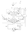
- FIG. 1 is a hydraulic circuit diagram of a hydraulic control apparatus according to the first embodiment of the present invention.
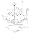
- FIG. 2 is a hydraulic circuit diagram showing a modification of the hydraulic control apparatus according to the first embodiment of the present invention.
- FIG. 3 is a hydraulic circuit diagram showing a modification of the hydraulic control apparatus according to the first embodiment of the present invention.
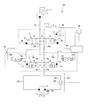
- FIG. 4 is a hydraulic circuit diagram of the hydraulic control apparatus according to the second embodiment of the present invention.
- FIG. 1 is a hydraulic circuit diagram illustrating a counter balance valve 10 and a fluid pressure control device 100 including the counter balance valve 10 according to the first embodiment.
- the fluid pressure control device 100 is mounted on a vehicle body of a working machine that is driven by fluid pressure, such as a power shovel or a wheel loader.
- fluid pressure such as a power shovel or a wheel loader.
- hydraulic oil is used as the working fluid, but other fluids such as working water may be used as the working fluid.
- a fluid pressure control apparatus 100 includes a pump 1 that discharges hydraulic oil, a hydraulic motor 2 that functions as a hydraulic motor driven by the hydraulic oil discharged from the pump 1, a pump 1, and a hydraulic motor 2.
- the direction switching valve 3 for switching the rotation direction of the hydraulic motor 2, the supply channel 21 for connecting the pump 1 and the direction switching valve 3, the hydraulic motor 2 and the direction switching valve 3 are provided.
- Supply / discharge passages 22a and 22b to be connected and a remote control valve 5 for controlling the pilot pressure of the direction switching valve 3 are provided.
- the pump 1 is driven by engine power (not shown) and discharges hydraulic oil to the supply flow path 21.
- the pump 1 is a swash plate type axial piston pump. Although the pump 1 is shown as a fixed capacity type in FIG. 1, the pump 1 is not limited to this and may be a variable capacity type.
- the hydraulic motor 2 is a swash plate type axial piston motor having a fixed capacity, and is used as a traveling hydraulic motor.
- the hydraulic motor 2 is rotationally driven in response to the supply of hydraulic oil discharged from the pump 1.
- the hydraulic motor 2 is switched to forward rotation or reverse rotation by the direction switching valve 3.
- the hydraulic motor 2 is not limited to a swash plate type axial piston motor having a fixed capacity, but may be a swash plate type axial piston motor having a variable capacity.
- the hydraulic motor 2 is provided with a negative parking brake 2a that applies a braking force to the hydraulic motor 2 when stopped.
- the parking brake 2 a is connected to a counter balance valve 10 described later by a flow path 23. When the pressure in the flow path 23 exceeds a predetermined pressure (brake release pressure), the parking brake 2a releases the brake and allows the hydraulic motor 2 to rotate.
- the direction switching valve 3 has a forward position A that guides hydraulic oil discharged from the pump 1 to the supply flow path 21 to the hydraulic motor 2 through the supply / discharge flow path 22a, and hydraulic oil discharged from the pump 1 to the supply flow path 21.
- the reverse position B which leads to the hydraulic motor 2 through the supply / discharge passage 22b, and the neutral position C where the pump 1 and the hydraulic motor 2 communicate with the tank T are provided.
- the direction switching valve 3 is switched by hydraulic fluid (pilot pressure) supplied from the pilot pump 4 to the pilot chambers 3 a and 3 b through the remote control valve 5 when the crew of the work machine operates the remote control valve 5.
- the direction switching valve 3 is switched to the forward position A, the remote control valve 5 is operated to the other side, and the pilot When the pressure is supplied to the pilot chamber 3b, the direction switching valve 3 is switched to the reverse position B.
- the remote control valve 5 is in the neutral position, that is, when the pilot pressure is not acting on any of the pilot chambers 3a and 3b, the direction switching valve 3 is driven by the biasing force of the springs 3c provided on both sides of the direction switching valve 3. Neutral position C is reached.
- the pilot pressure supplied to the pilot chambers 3 a and 3 b is controlled according to the operation amount of the remote control valve 5.
- the remote control valve 5 includes a position detection sensor 5 a that detects the neutral state of the remote control valve 5.
- the position detection sensor 5a outputs a detection signal to the controller 40 when the operation lever of the remote control valve 5 is in the neutral position.
- the direction switching valve 3 is also in a neutral state. That is, the neutral state of the direction switching valve 3 can be detected by the position detection sensor 5a.
- the position detection sensor 5a corresponds to a neutral state detector that detects that the direction switching valve 3 is in a neutral state.
- the fluid pressure control device 100 further includes a counter balance valve 10 provided between the direction switching valve 3 and the hydraulic motor 2.
- the counter balance valve 10 is provided in the supply / discharge passages 22a and 22b.
- the counter balance valve 10 includes valve-side passages 14a and 14b communicating with the direction switching valve 3 through the supply / discharge passages 22a and 22b, and motor-side passages 15a and 15b communicating with the hydraulic motor 2 through the supply / discharge passages 22a and 22b.
- the control valve 11 that controls the flow of hydraulic fluid between the valve side passages 14a and 14b and the motor side passages 15a and 15b when the direction switching valve 3 is switched, and the pilot pressure for controlling the control valve 11 Pilot chambers 11a and 11b, pilot passages 13a and 13b communicating with the valve side passages 14a and 14b and the pilot chambers 11a and 11b, and hydraulic fluid provided in the pilot passages 13a and 13b and flowing through the pilot passages 13a and 13b.
- Flow rate control valves 12a and 12b that variably control the flow rate of the.
- Pilot chambers 11a and 11b are provided at both ends of the control valve 11, respectively.
- the pilot passages 13a and 13b branch from the valve side passages 14a and 14b, respectively, and communicate with the pilot chambers 11a and 11b.
- the control valve 11 communicates the valve-side passage 14a with the motor-side passage 15a and the passage 23, and operates the valve-side passage 14b with the motor-side passage 15b.
- the control valve 11 guides the hydraulic oil discharged from the pump 1 to the pilot chamber 11a through the supply / discharge passage 22a, the valve side passage 14a, and the pilot passage 13a.
- the operation position D is switched.
- the control valve 11 allows the hydraulic oil discharged from the pump 1 to pass through the supply / discharge passage 22b, the valve side passage 14b, and the pilot passage 13b. Is switched to the operation position E.
- control valve 11 allows the hydraulic oil in the pilot chambers 11a and 11b to flow through the pilot passages 13a and 13b, the valve side passages 14a and 14b, and the supply / discharge passage. It is discharged to the tank T through 22a and 22b and switched to the neutral position F by the urging force of the springs 11c provided on both sides.
- the flow control valves 12a and 12b are electromagnetic proportional control valves including an electromagnetic proportional solenoid. When it is detected that the direction switching valve 3 is in the neutral state, the flow rate control valves 12a and 12b change the flow path area based on the current applied from the controller 40, thereby allowing the pilot passages 13a and 13b to flow. Controls the flow rate of flowing hydraulic oil. That is, the flow control valves 12a and 12b function as variable throttles.
- the flow rate control valves 12a and 12b are such that the flow area (throttle) is minimized when no current is applied from the controller 40, and the flow area (throttle) increases as the current applied from the controller 40 increases. Controlled.
- the flow rate control valves 12a and 12b control the pressure of the hydraulic oil in the pilot chambers 11a and 11b by controlling the flow rate of the hydraulic oil flowing through the pilot passages 13a and 13b, and adjust the switching speed of the control valve 11.
- the fluid pressure control device 100 includes an inclination angle sensor 30 as an inclination angle detection unit that detects the inclination angle of the vehicle body of the work machine, and a flow rate sensor 50 as a flow rate detection unit that detects the flow rate of hydraulic oil flowing through the hydraulic motor 2.
- an inclination angle sensor 30 as an inclination angle detection unit that detects the inclination angle of the vehicle body of the work machine
- a flow rate sensor 50 as a flow rate detection unit that detects the flow rate of hydraulic oil flowing through the hydraulic motor 2.
- the tilt angle sensor 30 detects the tilt angle in the front-rear direction with respect to the horizontal plane of the vehicle body of the work machine, and outputs the detected tilt angle to the controller 40.
- the flow rate sensor 50 is provided in the supply / discharge flow path 22a, detects the flow rate of the hydraulic oil flowing through the supply / discharge flow path 22a, and outputs the detected flow rate to the controller 40.
- the flow sensor 50 may be provided in the supply / discharge flow path 22b.
- the control valve 11 is switched to the operating position D.
- the direction switching valve 3 since the direction switching valve 3 is not in a neutral state, no current is applied from the controller 40 to the flow control valve 12a. Therefore, the flow area of the flow control valve 12a is minimized. For this reason, since the flow of the hydraulic oil flowing through the pilot passage 13a is restricted by the flow rate control valve 12a, it gradually flows into the pilot chamber 11a. As a result, the control valve 11 is gradually switched to the operating position D.
- the flow rate of the hydraulic oil flowing through the supply / discharge channel 22 a is detected by the flow rate sensor 50, and the detected flow rate is output to the controller 40.
- the hydraulic oil discharged from the hydraulic motor 2 returns to the tank T through the supply / discharge passage 22b, the motor side passage 15b, the control valve 11, the valve side passage 14b, the supply / discharge passage 22b, and the direction switching valve 3. It is.
- valve side passage 14 a communicates with the tank T through the supply / discharge flow path 22 a and the direction switching valve 3.
- the hydraulic oil in the pilot chamber 11a is discharged to the tank T through the pilot passage 13a, the valve side passage 14a, the supply / discharge passage 22a, and the direction switching valve 3.
- the position detection sensor 5a provided on the remote control valve 5 detects that the operation lever of the remote control valve 5 is in the neutral state, and outputs a detection signal to the controller 40.
- the controller 40 applies a current corresponding to the inclination angle detected by the inclination angle sensor 30 to the flow control valve 12a. Specifically, if the work implement is in a horizontal state, the controller 40 does not apply a current to the flow control valve 12a, and if the work implement is tilted forward and downward, the inclination angle of the vehicle body is large. From time to time, a large current is applied to the flow control valve 12a.
- the communication between the valve side passage 14a and the motor side passage 15a is such that the vehicle body is in a horizontal state. As compared with a certain case, it is shut off earlier, and the braking force for the hydraulic motor 2 is generated earlier. In this way, the fluid pressure control device 100 can quickly generate the braking force for the hydraulic motor 2 when the work implement is traveling forward on a downhill, and therefore the braking distance when the work implement is stopped. Can be shortened.
- the flow rate of the supply / discharge flow path 22a detected by the flow rate sensor 50 is input to the controller 40.
- the controller 40 applies a current corresponding to the flow rate detected by the flow rate sensor 50 to the flow rate control valve 12a.
- the controller 40 applies a larger current to the flow control valve 12a as the flow rate increases. Since the flow rate detected by the flow sensor 50 is equal to the flow rate of the hydraulic oil supplied to the hydraulic motor 2, the rotation speed of the hydraulic motor 2 is faster if the flow rate detected by the flow sensor 50 is large. That is, as the rotational speed of the hydraulic motor 2 increases, a larger current is applied to the flow control valve 12a and the flow path area increases.
- the switching speed of the control valve 11 is increased.
- the rotational speed of the hydraulic motor 2 is fast
- the switching speed of the control valve 11 is fast, so that the control valve 11 is quickly switched from the operating position D to the neutral position F. Therefore, when the rotation speed of the hydraulic motor 2 is high, that is, when the speed of the work machine is high, the switching speed of the control valve 11 is high, so that the communication between the valve side passage 14a and the motor side passage 15a is the hydraulic motor.
- the motor is shut off earlier, and the braking force for the hydraulic motor 2 is generated earlier.
- the fluid pressure control device 100 can generate the braking force against the hydraulic motor 2 quickly, and thus the braking distance of the work implement can be shortened.
- the hydraulic oil discharged from the pump 1 is supplied to the supply passage 21, the direction switching valve 3, the supply / discharge passage 22b, the valve side passage 14b, the control valve 11, and the motor side passage. It is supplied to the hydraulic motor 2 through 15b and the supply / discharge passage 22b.
- the hydraulic oil discharged from the pump 1 is supplied from the control valve 11 through the flow path 23 to the parking brake 2a, and the parking brake 2a is released.
- the hydraulic motor 2 rotates in the reverse direction and the work implement moves backward.
- the hydraulic oil discharged from the hydraulic motor 2 returns to the tank T through the supply / discharge passage 22a, the motor side passage 15a, the control valve 11, the valve side passage 14a, the supply / discharge passage 22a, and the direction switching valve 3. It is. At this time, the flow rate of the hydraulic oil flowing through the supply / discharge channel 22 a is detected by the flow sensor 50, and the detected flow rate is output to the controller 40.
- valve side passage 14b communicates with the tank T through the supply / discharge passage 22b and the direction switching valve 3. Thereby, the hydraulic oil in the pilot chamber 11 b is discharged to the tank T through the pilot passage 13 b, the valve side passage 14 b, the supply / discharge passage 22 b and the direction switching valve 3.
- the position detection sensor 5a provided on the remote control valve 5 detects that the operation lever of the remote control valve 5 is in the neutral state, and outputs a detection signal to the controller 40.
- the controller 40 applies a current corresponding to the inclination angle detected by the inclination angle sensor 30 to the flow control valve 12b. Specifically, if the work implement is in a horizontal state, the controller 40 does not apply a current to the flow rate control valve 12b, and if the work implement is inclined backward and downward, the inclination angle of the vehicle body is large. From time to time, a large current is applied to the flow control valve 12b.
- the fluid pressure control device 100 can quickly generate the braking force for the hydraulic motor 2 when the work implement is traveling backward on a downhill, so that the braking distance when the work implement is stopped is low. Can be shortened.
- the flow rate of the supply / discharge flow path 22a detected by the flow rate sensor 50 is input to the controller 40.
- the controller 40 applies a current corresponding to the flow rate detected by the flow rate sensor 50 to the flow rate control valve 12b.
- the controller 40 applies a larger current to the flow control valve 12b as the flow rate increases. Since the flow rate detected by the flow sensor 50 is equal to the flow rate of the hydraulic oil supplied to the hydraulic motor 2, the rotation speed of the hydraulic motor 2 is faster if the flow rate detected by the flow sensor 50 is large. That is, as the rotational speed of the hydraulic motor 2 increases, a larger current is applied to the flow control valve 12b and the flow path area increases.
- the switching speed of the control valve 11 is increased.
- the rotational speed of the hydraulic motor 2 is fast
- the switching speed of the control valve 11 is fast, so that the control valve 11 is quickly switched from the operating position E to the neutral position F. Therefore, when the rotation speed of the hydraulic motor 2 is high, that is, when the speed of the work machine is high, the switching speed of the control valve 11 is high, and therefore the communication between the valve side passage 14b and the motor side passage 15b is the hydraulic motor.
- the motor is shut off earlier, and the braking force for the hydraulic motor 2 is generated earlier.
- the fluid pressure control device 100 can generate the braking force against the hydraulic motor 2 quickly, so that the brake distance of the work implement can be shortened.
- the flow control valves 12a and 12b have been described using an electromagnetic proportional control valve as an example, a two-position electromagnetic switching valve may be used.
- a threshold value may be provided for the tilt angle detected by the tilt angle sensor 30 and the flow rate detected by the flow rate sensor 50, and the position of the electromagnetic switching valve may be switched when the threshold value is exceeded.
- the flow control valves 12a and 12b may be rotary valves 60a and 60b driven by an electric motor as shown in FIG.
- highly accurate control can be performed by detecting the rotation angle with a rotation angle sensor or the like and performing feedback control.
- a stepping motor or the like is employed as the electric motor, but any type of electric motor may be used as long as the rotation angle can be detected.
- the flow rate control valves 12a and 12b may be provided with a stroke sensor 12c that detects the stroke of the valve body of the flow rate control valves 12a and 12b. By controlling the stroke of the valve element detected by the stroke sensor 12c while feeding back, more accurate control can be performed.
- the controller 40 is configured to control the flow control valves 12a and 12b.
- the flow control valves 12a and 12b may be variable throttles that are manually operated. Even with such a configuration, the switching speed of the control valve 11 can be adjusted as appropriate.
- the fluid pressure control device 100 may be configured to control the flow control valves 12a and 12b only by the inclination angle detected by the inclination angle sensor 30 or only by the flow rate detected by the flow sensor 50. Furthermore, the flow control valves 12a and 12b may be configured to include only the flow control valve 12a on the forward side.
- the controller 40 may control the flow rate control valves 12a and 12b including not only when the vehicle body is lowered forward but also when the vehicle body is raised forward. For example, when the direction switching valve 3 is in the neutral state, a constant current may be applied to the flow control valves 12a and 12b, and the applied current may be increased or decreased according to the inclination angle of the vehicle body.
- the counter balance valve 10 includes flow rate control valves 12a and 12b that variably control the flow rate of the hydraulic oil flowing through the pilot passages 13a and 13b. Therefore, the switching speed of the control valve 11 can be adjusted by controlling the flow rate of the hydraulic oil flowing into the pilot chambers 11a and 11b of the control valve 11 or discharged from the pilot chambers 11a and 11b. Thereby, since the timing at which the control valve 11 cuts off the communication between the hydraulic motor 2 and the pump 1 can be adjusted as appropriate, the braking of the hydraulic motor 2 can be adjusted. Therefore, the braking distance of the vehicle body can be adjusted appropriately.
- the flow rate control valves 12a and 12b are moved by the inclination angle sensor 30 when the direction switching valve 3 is returned from the forward position A or the reverse position B where the hydraulic motor 2 is operated to the neutral position C where the hydraulic motor 2 is stopped.
- the flow of hydraulic oil discharged from the pilot chambers 11a and 11b is controlled according to the detected inclination angle and the flow rate detected by the flow rate sensor 50.
- the fluid pressure control device 100 includes a position detection sensor 5a that detects that the direction switching valve 3 is in a neutral state and an inclination angle sensor 30 that detects the inclination angle of the vehicle body, and the flow control valves 12a and 12b. Is controlled according to the inclination angle detected by the inclination angle sensor 30 when the neutral state is detected by the position detection sensor 5a. Thereby, when stopping the hydraulic motor 2, the switching speed of the control valve 11 is adjusted according to the inclination angle detected by the inclination angle sensor 30, and the timing at which the communication between the hydraulic motor 2 and the pump 1 is cut off. adjust.
- the fluid pressure control device 100 can generate a braking force against the hydraulic motor 2 according to the inclination angle of the vehicle body by the counter balance valve 10, so that even when the vehicle body is inclined forward and downward, The vehicle body can be braked at an appropriate braking distance.
- the fluid pressure control device 100 includes a flow rate sensor 50 that detects the flow rate of the hydraulic oil flowing through the hydraulic motor 2, and the flow rate control valves 12 a and 12 b are controlled according to the flow rate detected by the flow rate sensor 50.
- the switching speed of the control valve 11 is adjusted according to the flow rate detected by the flow sensor 50 to adjust the timing for disconnecting the communication between the hydraulic motor 2 and the pump 1. . Therefore, the fluid pressure control device 100 can generate a braking force for the hydraulic motor 2 in accordance with the speed of the work implement by the counter balance valve 10. It is possible to brake with a simple braking distance.
- FIG. 4 a fluid pressure control apparatus 200 according to a second embodiment of the present invention will be described. Below, it demonstrates centering on a different point from 1st Embodiment mentioned above, the same code
- the flow rate of the hydraulic oil flowing to the hydraulic motor 2 is detected by the flow sensor 50, whereas in the second embodiment, the flow rate of the hydraulic oil flowing to the hydraulic motor 2 is detected from the differential pressure gauge 70 and the rotational speed sensor 80. It differs in the point calculated by. This will be specifically described below.
- the fluid pressure control device 200 includes a differential pressure gauge 70 as a differential pressure detection unit that detects a differential pressure between a supply side and a discharge side in the hydraulic motor 2 and a rotation as a rotation number detection unit that detects the rotation number of the hydraulic motor 2.
- a number sensor 80 The differential pressure gauge 70 detects the pressure in the supply / discharge flow path 22 a and the supply / discharge flow path 22 b and outputs the difference between them to the controller 40.
- the rotation speed sensor 80 is provided in the vicinity of the rotation shaft of the hydraulic motor 2, detects the rotation speed of the rotation shaft, and outputs the rotation speed of the hydraulic motor 2 to the controller 40.
- a map indicating the relationship between the differential pressure detected in advance by the differential pressure gauge 70 and the volumetric efficiency of the hydraulic motor 2 is stored.
- the controller 40 calculates the flow rate of the hydraulic motor 2 based on the rotational speed detected by the rotational speed sensor 80, the differential pressure detected by the differential pressure gauge 70, and the map described above.
- the flow rate control valves 12a and 12b are controlled by the flow rate thus obtained in the same manner as in the first embodiment.
- pressure gauges may be installed on the supply side and the discharge side in the hydraulic motor 2, and control may be performed based on the pressure difference detected by these pressure gauges.
- the flow control valves 12a and 12b can be controlled more accurately. Thereby, according to the rotational speed of the hydraulic motor 2, the braking distance of a vehicle body can be adjusted more appropriately.
- the counter balance valve 10 is configured so that the valve side passages 14a and 14b communicating with the direction switching valve 3, the motor side passages 15a and 15b communicating with the fluid pressure motor (hydraulic motor 2), and the direction switching valve 3 are switched.
- a control valve 11 for controlling the flow of hydraulic oil between the valve side passages 14a, 14b and the motor side passages 15a, 15b; pilot chambers 11a, 11b to which pilot pressure for controlling the control valve 11 is guided; Pilot passages 13a and 13b communicating with the side passages 14a and 14b and the pilot chambers 11a and 11b, and flow rate control valves 12a and 12b for variably controlling the flow rate of the hydraulic oil flowing through the pilot passages 13a and 13b are provided.
- the counter balance valve 10 includes the flow rate control valves 12a and 12b that variably control the flow rate of the hydraulic oil flowing through the pilot passages 13a and 13b. Therefore, the counter balance valve 10 flows into the pilot chambers 11a and 11b of the control valve 11 or pilot chamber 11a.
- the switching speed of the control valve 11 can be adjusted by adjusting the flow rate of the hydraulic oil discharged from 11b. Thereby, since the timing at which the control valve 11 cuts off the communication between the fluid pressure motor (hydraulic motor 2) and the pump 1 can be adjusted as appropriate, the braking of the fluid pressure motor (hydraulic motor 2) can be adjusted. . Therefore, the braking distance of the vehicle body can be adjusted appropriately.
- the flow control valves 12a and 12b are configured so that the direction switching valve 3 moves from the position (forward position A or reverse position B) where the fluid pressure motor (hydraulic motor 2) operates to the fluid pressure motor (hydraulic motor 2). ) Is switched to a position (neutral position C) to stop, the flow path area is controlled to be large.
- the flow control valves 12a and 12b stop the fluid pressure motor (hydraulic motor 2) from the position (forward position A or reverse position B) where the direction switching valve 3 operates the fluid pressure motor (hydraulic motor 2).
- the flow path area increases.
- blocks communication with a fluid pressure motor (hydraulic motor 2) and the pump 1 can be advanced, and it can suppress that the braking distance of a vehicle body extends.
- the pilot chambers 11a and 11b are provided at both ends of the control valve 11, and the flow rate control valves 12a and 12b are respectively pilot passages for introducing pilot pressure to the pilot chambers 11a and 11b.
- the flow rate control valves 12a and 12b are respectively pilot passages for introducing pilot pressure to the pilot chambers 11a and 11b.
- 13a and 13b Provided in 13a and 13b.
- the switching speed of the control valve 11 can be adjusted regardless of which direction the fluid pressure motor (hydraulic motor 2) is operated.
- the distance can be adjusted appropriately.
- the flow control valves 12a and 12b are electromagnetic switching valves.
- the flow control valves 12a and 12b are rotary valves 60a and 60b driven by an electric motor.
- the flow control valves 12a and 12b are electromagnetic proportional control valves.
- the flow control valves 12a and 12b further include a stroke sensor 12c for detecting the movement amount of the valve body.
- the fluid pressure control device 100 includes a pump 1 that discharges hydraulic oil, a fluid pressure motor (hydraulic motor 2) that is driven by the hydraulic oil discharged from the pump 1, and a pump 1 and a fluid pressure motor (hydraulic motor 2).
- a direction switching valve 3 that is provided in the flow path to be connected and switches the rotation direction of the fluid pressure motor (hydraulic motor 2), and a counter that is provided between the direction switching valve 3 and the fluid pressure motor (hydraulic motor 2) in the flow path.
- a balance valve 10 10.
- the fluid pressure control device 100 includes a neutral state detection unit (position detection sensor 5a) that detects that the direction switching valve 3 is in a neutral state, and an inclination angle detection unit (inclination angle sensor 30) that detects the inclination angle of the vehicle body. ), And the flow rate control valves 12a and 12b are detected by the inclination angle detection unit (inclination angle sensor 30) when the neutral state is detected by the neutral state detection unit (position detection sensor 5a). It is controlled according to.
- position detection sensor 5a position detection sensor 5a
- inclination angle detection unit inclination angle sensor 30
- the flow rate control valves 12a and 12b are controlled according to the inclination angle of the vehicle body when the direction switching valve 3 is in the neutral state, so that the control when the fluid pressure motor (hydraulic motor 2) stops is performed.
- the switching speed of the valve 11 can be adjusted according to the inclination angle of the vehicle body. Therefore, the fluid pressure motor (hydraulic motor 2) can be appropriately braked in a state where the vehicle body is inclined. Thereby, the braking distance of the vehicle body can be appropriately adjusted according to the state in which the vehicle body is inclined.
- the fluid pressure control device 100 further includes a flow rate detection unit (flow rate sensor 50) that detects the flow rate of the hydraulic oil flowing through the fluid pressure motor (hydraulic motor 2), and the flow rate control valves 12a and 12b include the flow rate detection unit ( The flow rate is controlled according to the flow rate detected by the flow rate sensor 50).
- a flow rate detection unit flow rate sensor 50
- the flow rate is controlled according to the flow rate detected by the flow rate sensor 50.
- the flow rate control valves 12a and 12b are controlled in accordance with the flow rate detected by the flow rate detection unit (flow rate sensor 50). It can be adjusted according to the speed. Thereby, the braking distance of the vehicle body can be appropriately adjusted according to the rotational speed of the fluid pressure motor (hydraulic motor 2).
- the fluid pressure control device 100 includes a differential pressure detection unit (differential pressure gauge 70) that detects a differential pressure between the supply side and the discharge side in the fluid pressure motor (hydraulic motor 2), and a fluid pressure motor (hydraulic motor 2).
- a rotational speed detection unit (rotational speed sensor 80) for detecting the rotational speed, and the flow rate control valves 12a and 12b include a differential pressure and rotational speed detection unit (detected by the differential pressure detection unit (differential pressure gauge 70)). It is controlled according to the rotational speed detected by the rotational speed sensor 80).
- the fluid pressure motor (hydraulic motor 2) based on the differential pressure between the supply side and the discharge side in the fluid pressure motor (hydraulic motor 2) and the rotation speed of the fluid pressure motor (hydraulic motor 2), the fluid pressure motor (hydraulic motor 2) The operating state can be detected. Since the differential pressure between the supply side and the discharge side in the fluid pressure motor (hydraulic motor 2) and the rotation speed of the fluid pressure motor (hydraulic motor 2) have small measurement errors, the flow rate can be calculated with high accuracy. Therefore, the flow control valves 12a and 12b can be controlled more accurately. Thereby, the braking distance of the vehicle body can be adjusted more appropriately according to the rotational speed of the fluid pressure motor (hydraulic motor 2).
- an oil temperature sensor that detects the oil temperature may be provided in the supply / discharge passages 22a and 22b. Since the viscosity of the hydraulic oil can be calculated from the detected oil temperature, it can be controlled with higher accuracy by controlling the flow rate control valves 12a and 12b using a correction coefficient (or map) corresponding to the viscosity.
- the hydraulic motor 2 has been described as an example for traveling, but may be used for turning.
- a sensor for detecting the position of the valve body of the direction switching valve 3 may be provided.
- the neutral state of the direction switching valve 3 may be detected by detecting the pressure of the pilot flow path communicating with the pilot chambers 3a and 3b or the pilot chambers 3a and 3b.
Landscapes
- Engineering & Computer Science (AREA)
- General Engineering & Computer Science (AREA)
- Physics & Mathematics (AREA)
- Fluid Mechanics (AREA)
- Mining & Mineral Resources (AREA)
- Civil Engineering (AREA)
- Structural Engineering (AREA)
- Mechanical Engineering (AREA)
- Chemical & Material Sciences (AREA)
- Analytical Chemistry (AREA)
- Fluid-Pressure Circuits (AREA)
- Operation Control Of Excavators (AREA)
Priority Applications (2)
| Application Number | Priority Date | Filing Date | Title |
|---|---|---|---|
| EP16865999.3A EP3379090A1 (en) | 2015-11-20 | 2016-09-09 | Counter balance valve and fluid pressure control device provided with counter balance valve |
| KR1020187013427A KR20180066210A (ko) | 2015-11-20 | 2016-09-09 | 카운터 밸런스 밸브 및 카운터 밸런스 밸브를 구비한 유체압 제어 장치 |
Applications Claiming Priority (2)
| Application Number | Priority Date | Filing Date | Title |
|---|---|---|---|
| JP2015227811A JP6268146B2 (ja) | 2015-11-20 | 2015-11-20 | カウンタバランス弁及びカウンタバランス弁を備えた流体圧制御装置 |
| JP2015-227811 | 2015-11-20 |
Publications (1)
| Publication Number | Publication Date |
|---|---|
| WO2017085996A1 true WO2017085996A1 (ja) | 2017-05-26 |
Family
ID=58718082
Family Applications (1)
| Application Number | Title | Priority Date | Filing Date |
|---|---|---|---|
| PCT/JP2016/076678 Ceased WO2017085996A1 (ja) | 2015-11-20 | 2016-09-09 | カウンタバランス弁及びカウンタバランス弁を備えた流体圧制御装置 |
Country Status (4)
| Country | Link |
|---|---|
| EP (1) | EP3379090A1 (enExample) |
| JP (1) | JP6268146B2 (enExample) |
| KR (1) | KR20180066210A (enExample) |
| WO (1) | WO2017085996A1 (enExample) |
Cited By (2)
| Publication number | Priority date | Publication date | Assignee | Title |
|---|---|---|---|---|
| WO2019189031A1 (ja) * | 2018-03-28 | 2019-10-03 | 住友建機株式会社 | ショベル |
| WO2020162377A1 (ja) * | 2019-02-08 | 2020-08-13 | 川崎重工業株式会社 | 液圧ポンプ流量較正システム |
Families Citing this family (1)
| Publication number | Priority date | Publication date | Assignee | Title |
|---|---|---|---|---|
| JP6903541B2 (ja) * | 2017-10-03 | 2021-07-14 | 株式会社クボタ | 作業機の油圧システム |
Citations (2)
| Publication number | Priority date | Publication date | Assignee | Title |
|---|---|---|---|---|
| JPH04138103U (ja) * | 1991-06-19 | 1992-12-24 | 株式会社小松製作所 | カウンタバランス弁 |
| JPH08277547A (ja) * | 1995-04-07 | 1996-10-22 | Shin Caterpillar Mitsubishi Ltd | 車両の走行系制御回路 |
Family Cites Families (1)
| Publication number | Priority date | Publication date | Assignee | Title |
|---|---|---|---|---|
| JPS5715157A (en) * | 1980-07-03 | 1982-01-26 | Kawasaki Heavy Ind Ltd | Brake valve |
-
2015
- 2015-11-20 JP JP2015227811A patent/JP6268146B2/ja active Active
-
2016
- 2016-09-09 WO PCT/JP2016/076678 patent/WO2017085996A1/ja not_active Ceased
- 2016-09-09 KR KR1020187013427A patent/KR20180066210A/ko not_active Withdrawn
- 2016-09-09 EP EP16865999.3A patent/EP3379090A1/en not_active Withdrawn
Patent Citations (2)
| Publication number | Priority date | Publication date | Assignee | Title |
|---|---|---|---|---|
| JPH04138103U (ja) * | 1991-06-19 | 1992-12-24 | 株式会社小松製作所 | カウンタバランス弁 |
| JPH08277547A (ja) * | 1995-04-07 | 1996-10-22 | Shin Caterpillar Mitsubishi Ltd | 車両の走行系制御回路 |
Cited By (12)
| Publication number | Priority date | Publication date | Assignee | Title |
|---|---|---|---|---|
| WO2019189031A1 (ja) * | 2018-03-28 | 2019-10-03 | 住友建機株式会社 | ショベル |
| CN111670287A (zh) * | 2018-03-28 | 2020-09-15 | 住友建机株式会社 | 挖土机 |
| JPWO2019189031A1 (ja) * | 2018-03-28 | 2021-03-18 | 住友建機株式会社 | ショベル |
| EP3779062A4 (en) * | 2018-03-28 | 2021-05-26 | Sumitomo (S.H.I.) Construction Machinery Co., Ltd. | SHOVEL |
| JP7341982B2 (ja) | 2018-03-28 | 2023-09-11 | 住友建機株式会社 | ショベル |
| US11913194B2 (en) | 2018-03-28 | 2024-02-27 | Sumitomo Construction Machinery Co., Ltd. | Shovel |
| WO2020162377A1 (ja) * | 2019-02-08 | 2020-08-13 | 川崎重工業株式会社 | 液圧ポンプ流量較正システム |
| JP2020128733A (ja) * | 2019-02-08 | 2020-08-27 | 川崎重工業株式会社 | 液圧ポンプ流量較正システム |
| GB2595184A (en) * | 2019-02-08 | 2021-11-17 | Kawasaki Heavy Ind Ltd | Hydraulic-pump flow-rate calibration system |
| GB2595184B (en) * | 2019-02-08 | 2022-11-16 | Kawasaki Heavy Ind Ltd | Hydraulic-pump flow-rate calibration system |
| JP7499564B2 (ja) | 2019-02-08 | 2024-06-14 | 川崎重工業株式会社 | 液圧ポンプ流量較正システム |
| US12404655B2 (en) | 2019-02-08 | 2025-09-02 | Kawasaki Jukogyo Kabushiki Kaisha | Hydraulic-pump flow-rate calibration system |
Also Published As
| Publication number | Publication date |
|---|---|
| JP6268146B2 (ja) | 2018-01-24 |
| KR20180066210A (ko) | 2018-06-18 |
| JP2017096368A (ja) | 2017-06-01 |
| EP3379090A1 (en) | 2018-09-26 |
Similar Documents
| Publication | Publication Date | Title |
|---|---|---|
| JP5628832B2 (ja) | 流体力を補償する油圧制御システム | |
| US8286748B2 (en) | Work vehicle | |
| CN102549313B (zh) | 作业车辆 | |
| US8418798B2 (en) | Industrial vehicle | |
| EP2105638B1 (en) | Traveling system for construction equipment | |
| JP6335093B2 (ja) | 建設機械の油圧駆動システム | |
| CN104379945B (zh) | 建筑机械的控制系统 | |
| US6564549B2 (en) | Displacement control device for hydraulic pump and brake control device for hydraulic motor | |
| US10106955B2 (en) | Turning control apparatus | |
| WO2008004589A1 (en) | Motor control device for construction machine | |
| US20120145494A1 (en) | Vehicle brake device | |
| CN110914503B (zh) | 作业车辆以及作业车辆的控制方法 | |
| JP5412011B1 (ja) | ホイールローダ | |
| WO2013146409A1 (ja) | ブーム駆動装置 | |
| US10071719B2 (en) | Hydrostatic traction drive in closed hydraulic circuit and method for controlling the hydrostatic traction drive | |
| WO2010092701A1 (ja) | 液圧モータ | |
| JP6268146B2 (ja) | カウンタバランス弁及びカウンタバランス弁を備えた流体圧制御装置 | |
| WO2019065925A1 (ja) | 作業機械 | |
| CN111615574A (zh) | 回转式工程机械 | |
| JP6075866B2 (ja) | ポンプ制御装置 | |
| JP2009522147A (ja) | 車両操舵装置および方法 | |
| WO2015151776A1 (ja) | 作業機械の油圧制御装置 | |
| JP6335340B1 (ja) | 作業機械 | |
| JP6491501B2 (ja) | ショベル | |
| JP2017096368A5 (enExample) |
Legal Events
| Date | Code | Title | Description |
|---|---|---|---|
| 121 | Ep: the epo has been informed by wipo that ep was designated in this application |
Ref document number: 16865999 Country of ref document: EP Kind code of ref document: A1 |
|
| ENP | Entry into the national phase |
Ref document number: 20187013427 Country of ref document: KR Kind code of ref document: A |
|
| NENP | Non-entry into the national phase |
Ref country code: DE |
|
| WWE | Wipo information: entry into national phase |
Ref document number: 2016865999 Country of ref document: EP |
|
| ENP | Entry into the national phase |
Ref document number: 2016865999 Country of ref document: EP Effective date: 20180620 |