WO2017085876A1 - 質量分析装置 - Google Patents
質量分析装置 Download PDFInfo
- Publication number
- WO2017085876A1 WO2017085876A1 PCT/JP2015/082745 JP2015082745W WO2017085876A1 WO 2017085876 A1 WO2017085876 A1 WO 2017085876A1 JP 2015082745 W JP2015082745 W JP 2015082745W WO 2017085876 A1 WO2017085876 A1 WO 2017085876A1
- Authority
- WO
- WIPO (PCT)
- Prior art keywords
- sample
- sample plate
- plate
- mass spectrometer
- identifier
- Prior art date
- Legal status (The legal status is an assumption and is not a legal conclusion. Google has not performed a legal analysis and makes no representation as to the accuracy of the status listed.)
- Ceased
Links
Images


Classifications
-
- H—ELECTRICITY
- H01—ELECTRIC ELEMENTS
- H01J—ELECTRIC DISCHARGE TUBES OR DISCHARGE LAMPS
- H01J49/00—Particle spectrometers or separator tubes
- H01J49/02—Details
- H01J49/04—Arrangements for introducing or extracting samples to be analysed, e.g. vacuum locks; Arrangements for external adjustment of electron- or ion-optical components
- H01J49/0409—Sample holders or containers
-
- G—PHYSICS
- G01—MEASURING; TESTING
- G01N—INVESTIGATING OR ANALYSING MATERIALS BY DETERMINING THEIR CHEMICAL OR PHYSICAL PROPERTIES
- G01N27/00—Investigating or analysing materials by the use of electric, electrochemical, or magnetic means
- G01N27/62—Investigating or analysing materials by the use of electric, electrochemical, or magnetic means by investigating the ionisation of gases, e.g. aerosols; by investigating electric discharges, e.g. emission of cathode
- G01N27/64—Investigating or analysing materials by the use of electric, electrochemical, or magnetic means by investigating the ionisation of gases, e.g. aerosols; by investigating electric discharges, e.g. emission of cathode using wave or particle radiation to ionise a gas, e.g. in an ionisation chamber
Definitions
- the present invention relates to a mass spectrometer that performs mass analysis on a sample placed on a sample plate.
- sample preparation operation In order to analyze a sample such as a specimen with a mass spectrometer, an operation of placing the sample on a sample plate (sample preparation operation) is performed in advance. Along with the sample preparation work, work for associating the sample plate and the sample placed thereon is performed. In this operation, for example, the operator can use a barcode attached to the sample plate (a barcode that is an identifier of the sample plate) and a barcode attached to a sample container or the like placed on the sample plate.
- the barcode (identifier) is continuously read by a barcode reader and sent to a computer (data server) connected to the mass spectrometer.
- the data server stores the barcode of the sample plate (specifically, identification information of the sample plate that it indicates) and the barcode of the sample (specifically, identification information of the sample that it indicates) in association with each other. As a result, the sample plate and the sample placed thereon are linked.
- the operator of the mass spectrometer sets the sample plate on which the sample is placed one by one in the mass spectrometer, and causes the mass spectrometer to analyze the sample.
- the operator reads the barcode attached to the sample plate with a barcode reader and inputs it to the mass spectrometer before setting the sample plate on the mass spectrometer.
- the mass spectrometer recognizes which sample plate corresponds to the analysis information obtained by mass spectrometry.
- the sample plate and the sample placed thereon are linked in advance in the data server connected to the mass spectrometer, the correspondence between the sample plate and the analysis information is recognized, Analysis information and sample are linked.
- sample mix-up leads to a serious accident, so analysis information must be linked to the sample accurately and reliably.
- human error such as forgetting to read or missed reading cannot be completely eliminated. It was not possible to completely avoid the situation in which it is not possible to know which sample analysis information is the analysis information obtained.
- the problem to be solved by the present invention is to provide a technique capable of increasing the certainty of linking a sample and its analysis information in a mass spectrometer.
- the present invention made to solve the above problems is a mass spectrometer, An insertion slot into which the sample plate is inserted; A light irradiating unit arranged so that light enters the sample plate inserted from the insertion port, and a light receiving unit that receives reflected light or transmitted light from the sample plate and reads an identifier attached to the sample plate
- a reading device comprising: An analysis unit that performs mass analysis of the sample placed on the sample plate and acquires analysis information of the sample, A storage unit for storing the identification information of the sample plate indicated by the identifier read by the reader and the analysis information of the sample placed on the sample plate acquired by the analysis unit in association with each other; Is provided.
- the identifier attached to the sample plate is read by the reading device. Then, the identification information of the sample plate indicated by the read identifier is stored in association with the analysis information of the sample placed on the sample plate. According to this configuration, it is not necessary to manually read the identifier attached to the sample plate, so that human error such as forgetting to read or loss of reading does not occur. Therefore, the certainty of the association between the sample and the analysis information can be improved.
- the light receiving unit receives reflected light from the sample plate
- An identifier indicating the absence of the sample plate is disposed at a position opposite to the reading device across the sample plate inserted from the insertion port.
- the reader when there is no sample plate between the reader and the identifier indicating the absence of the sample plate (that is, when there is no sample plate inserted from the insertion port), the reader is a sample. An identifier indicating the absence of the plate will be read. Therefore, the presence / absence of the sample plate can be detected by using a reader for reading the identification information of the sample plate without specially providing a detector or the like for detecting the presence / absence of the sample plate.
- the identifier is a barcode;
- the reading device is a bar code reader.
- the barcode reader Since the barcode reader is small and inexpensive, it contributes to miniaturization of mass spectrometer and reduction of manufacturing cost.
- the identifier attached to the sample plate is read by the reading device. According to this configuration, it is not necessary to manually read the identifier attached to the sample plate, so that human error such as forgetting to read or loss of reading does not occur. Therefore, the certainty of the association between the sample and the analysis information can be improved.
- the mass spectrometer according to the embodiment is an apparatus that performs ionization by irradiating an object (sample) placed on a sample plate with laser light, and separates and detects flying ions according to a mass-to-charge ratio.
- the sample plate on which the sample is placed will be described with reference to FIG.
- FIG. 1 is a plan view of the sample plate 8.
- the sample plate 8 is a plate-like member, and a plurality of concave portions 81 are formed on the upper surface thereof, for example, in a matrix shape.
- the sample 9 is placed on the sample plate 8 by dropping the sample 9 into each of the plurality of recesses 81.
- this area 82 is also referred to as “handling area 82”.
- an identifier 80 indicating identification information (hereinafter also referred to as “plate information”) 800 (see FIG. 6) of the sample plate 8 is attached.
- the identifier 80 is in the form of a barcode, and the identifier 80 is attached to the sample plate 8 by sticking a seal 83 on which the barcode is printed to the handling area 82.
- the identifier 80 attached to the sample plate 8 is also referred to as “plate identifier 80”.
- Mass Spectrometer 10 according to Embodiment> The mass spectrometer according to the embodiment will be described with reference to FIG. FIG. 2 is a side view showing a part of the mass spectrometer 10. However, in FIG. 2, illustration of one side wall of the mass spectrometer 10 is omitted, and the stage 3 is shown in a cross-sectional shape.
- the mass spectrometer 10 includes an insertion port 1 for inserting the sample plate 8 into the internal space 110 of the device, and a door 2 for opening and closing the insertion port 1.
- a stage 3 on which the sample plate 8 is placed and a moving mechanism 4 that moves the stage 3 in the internal space 110 are arranged.
- the mass spectrometer 10 includes a control unit 5 that controls each unit included in the mass spectrometer 10 and executes a series of processes on the sample 9 on the sample plate 8.
- mass analysis is performed on the sample 9 on the sample plate 8.
- the sample 9 on the sample plate 8 placed on the stage 3 is ionized by irradiating the sample 9 with a laser beam from a laser light source (not shown) and extracting the ionized substance with the extraction electrode 11. Is done.
- the sample plate 8 the sample 9 is held in each of the plurality of recesses 81.
- the above processing is performed while the moving mechanism 4 moves the stage 3 relative to the laser light source so as to sequentially irradiate the sample 9 held in each concave portion 81 with the laser light.
- the substance extracted by the extraction electrode 11 is accelerated, separated according to the mass-to-charge ratio, and detected (configurations related to separation and detection are not shown).
- the internal space 110 is provided with an exhaust system (not shown), and the internal space 110 is in a vacuum state while the sample plate 8 is processed.
- the stage 3, the moving mechanism 4, the extraction electrode 11, the control unit 5, and various elements (not shown) cooperate to perform mass analysis of the sample 9 placed on the sample plate 8.
- the analysis unit 101 is configured.
- the internal space 110 may be divided into a plurality of spaces. For example, it may be divided into a processing space for performing processing and a load lock space for transferring the sample plate 8 between the outside of the apparatus and the processing space.
- a load lock space is disposed between the insertion port 1 and the processing space.
- the processing space and the load lock space are partitioned by, for example, a gate valve, and each space is configured to be independently switched between a vacuum state and an atmospheric state.
- FIG. 3 is a diagram showing how the sample plate 8 is exchanged with respect to the stage 3 arranged at the initial position.
- the mass spectrometer 10 When the sample plate 8 mass-analyzed by the mass spectrometer 10 is extracted from the insertion port 1 by the operator, the mass spectrometer 10 is ready to accept a new sample plate 8.
- the door 2 is opened (a state indicated by a one-dot chain line in FIG. 2), and the stage 3 is disposed at an initial position shown in FIGS.
- part of the stage 3 In the state in the initial position, part of the stage 3 is projected out of the insertion slot 1. That is, in the stage 3, when the sample plate 8 is placed here, the area portion 31 below the handling area 82 is notched (hereinafter also referred to as “notched area 31”).
- the cutout region 31 In the state where is in the initial position, the cutout region 31 is arranged outside the insertion slot 1.
- the operator can insert the sample plate 8 from the insertion port 1 and place it on the stage 3 while holding the handling area 82 of the sample plate 8 from above and below. Further, the operator can grasp the handling area 82 of the sample plate 8 placed on the stage 3 so as to sandwich the sample plate 8 from above and below, and extract the sample plate 8 from the insertion port 1.
- the door 2 When the sample plate 8 is placed on the stage 3 in the initial position (the lower stage in FIG. 3), the door 2 is closed and the internal space 110 is decompressed. When the internal space 110 reaches a predetermined degree of vacuum, the moving mechanism 4 starts to move the stage 3, and mass analysis for the sample 9 on the sample plate 8 placed here is started. When the mass analysis is completed, the stage 3 is returned to the initial position. Then, the door 2 is opened after the internal space 110 is in an atmospheric state (lower stage in FIG. 3). When the sample plate 8 is extracted by the operator, the mass spectrometer 10 is ready to accept a new sample plate 8 (upper stage in FIG. 3).
- the mass spectrometer 10 includes a reading device 6 that reads an identifier (plate identifier) 80 attached to the sample plate 8.
- the reading device 6 will be described with reference to FIGS. 4 and 5 in addition to FIGS.
- FIG. 4 is a diagram illustrating a state where the reading device 6 is reading the plate identifier 80.
- FIG. 5 is a diagram illustrating a state in which the reading device 6 is reading the blank identifier 70.
- the reading device 6 is a device that optically reads an object by irradiating the object with light and receiving reflected light.
- the reading device 6 includes a light irradiation unit 61 that emits the reading light 60 and a light receiving unit 62 that receives the reflected light of the reading light 60 emitted therefrom.
- the reading device 6 makes a reading target a plate identifier 80 attached to the sample plate 8.
- the plate identifier 80 is in the form of a barcode, the reading device 6 reads the barcode. Consists of possible barcode readers.
- the reading device 6 (specifically, the light irradiation unit 61 of the reading device 6) is configured so that the reading light 60 emitted from the reading device 6 is inserted into the sample plate 8 from the insertion port 1 (that is, the stage at the initial position). 3 is placed so as to be incident on the sample plate 8) placed on the plate 3). More specifically, the light irradiation unit 61 is above the insertion port 1 and the reading light 60 enters the handling region 82 of the sample plate 8 placed on the stage 3 at the initial position. Such a position (that is, a position where the reading light 60 enters the cutout region 31 of the stage 3 at the initial position) is arranged.
- the sample plate 8 inserted through the insertion port 1 (that is, the sample plate 8 placed on the stage 3 in the initial position) is sandwiched between the reader 6 and the sample plate 8 is not present.
- An identifier 70 (hereinafter also referred to as “blank identifier”) to be shown is arranged. More specifically, the blank identifier 70 is read across the handling area 82 of the sample plate 8 placed on the stage 3 at the initial position (that is, the cutout area 31 of the stage 3 at the initial position). It is arranged at a position opposite to the device 6. In the mass spectrometer 10, the inner wall surface 20 of the door 2 (opened door 2) is disposed at a position opposite to the reading device 6 across the notch region 31 of the stage 3 at the initial position.
- the blank identifier 70 is attached to the inner wall surface 20 here.
- the blank identifier 70 is in the form of a barcode, similar to the plate identifier 80, and the blank identifier 70 is attached to the inner wall surface 20 by sticking the seal printed with the barcode to the inner wall surface 20 of the door 2. Is done.
- the control unit 5 includes a storage device 51 (see FIG. 2).
- This storage device 51 stores a table 50.
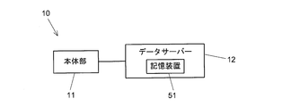
- the mass spectrometer 10 may include a main body 11 and a computer (data server) 12 connected thereto.
- the table 50 may be stored in the storage device 51 of the data server 12.
- FIG. 6 shows a configuration example of the management screen of the table 50 displayed on the display of the data server 12, for example.
- the table 50 includes plate information 800 indicated by the plate identifier 80, identification information (hereinafter also referred to as “sample information”) 900 of the sample 9, and analysis information obtained by the analysis unit 101 performing mass analysis on the sample 9 ( Specifically, for example, identification information 100 for specifying analysis information) is described.
- sample information hereinafter also referred to as “sample information”
- analysis information obtained by the analysis unit 101 performing mass analysis on the sample 9 Specifically, for example, identification information 100 for specifying analysis information
- the sample plate 8 is formed with a plurality of recesses 81
- the table 50 also includes position information 801 for specifying each recess 81.
- a combination of plate information 800 and position information 801 that is, information for specifying one recess 81
- one piece of sample information 900 and one piece of analysis information 100 are described in the one record.
- the pieces of information 800, 801, 900, 100 described in the same record can be linked on the table 50.
- the arrangement state of the sample 9 on the sample plate 8, the progress of the analysis process, and the like may be further displayed on the management screen of the table 50.
- FIG. 7 is a diagram (step S1 to step S3) showing a flow of work performed by an operator for mass analysis of the sample 9 by the mass spectrometer 10, and a flow of processing executed by the mass spectrometer 10.
- the figures shown (steps S11 to S14) are shown side by side.
- Step S1 First, an operation of placing the sample 9 on the sample plate 8 is performed (sample preparation operation). Specifically, this operation is performed, for example, by the operator dropping the sample 9 into each of the plurality of recesses 81 on the sample plate 8.
- Step S2 Subsequently, an operation for associating the sample plate 8 (specifically, each concave portion 81 of the sample plate 8) with the sample 9 placed thereon in the mass spectrometer 10 is performed. Specifically, this operation is performed as follows, for example. That is, the operator reads the plate identifier 80 attached to the sample plate 8 with a handy type reading device (for example, a handy type bar code reader), and the mass spectrometer 10 (specifically, for example, To the data server 12). Further, the operator sends information (position information) 801 for specifying one recess 81 in the sample plate 8 to the mass spectrometer 10.
- a handy type reading device for example, a handy type bar code reader
- the operator uses an identifier (identifier indicating the sample information 900) attached to the container or the like of the sample 9 (sample 9 placed in the recess 81) as a handy type reading device (for example, handy type).
- a handy type reading device for example, handy type.
- the control unit 5 of the mass spectrometer 10 interprets the received plate identifier 80 to specify the plate information 800 indicated by the plate identifier 80 and refers to the position information 801 to specify one recess 81.
- the identifier of the received sample is interpreted and the sample information 900 indicated by this is specified.
- Each information 800, 801, 900 is described in the same record in the table 50. Accordingly, the plate information 800 that is identification information of the sample plate 8 and the sample information 900 that is identification information of the sample 9 placed in one concave portion (the concave portion indicated by the position information 801) 81 in the sample plate 8. Are associated and stored.
- Step S3 The sample plate 8 on which the sample 9 is placed is transported to the mass spectrometer 10, and the operator of the mass spectrometer 10 sets the sample plate 8 in the mass spectrometer 10. Specifically, as described above, the operator grasps the handling region 82 of the sample plate 8 from above and below, inserts the sample plate 8 from the insertion port 1, and moves the stage 3 (positioned at the initial position). Placed on stage 3).
- Step S11 In the mass spectrometer 10, while the power is turned on, the reading operation of the reading device 6 is always performed (that is, the light irradiation unit 61 is in the ON state), and the control unit 5 The presence or absence of the sample plate 8 is monitored based on the information acquired by the reading device 6. That is, when the door 2 is in an open state and the sample plate 8 is not placed on the stage 3 disposed at the initial position, the reading device 6 reads the blank identifier 70 as described above (shown in FIG. 5). Status). The control unit 5 determines that there is no sample plate 8 inserted from the insertion port 1 while the reading device 6 is reading the blank identifier 70.
- the reading device 6 reads the plate identifier 80 attached to the sample plate 8 (the state shown in FIG. 4).
- the control unit 5 determines that the sample plate 8 inserted from the insertion port 1 exists.
- Step S12 When the reading device 6 reads the plate identifier 80 (YES in step S11), the control unit 5 determines that the sample plate 8 inserted from the insertion port 1 is present, and controls each unit of the mass spectrometer 10. Thus, mass analysis is performed on the sample 9 on the sample plate 8. Specifically, the door 2 is closed and the internal space 110 is decompressed under the control of the control unit 5. When the internal space 110 reaches a predetermined degree of vacuum, the moving mechanism 4 starts moving the stage 3, and mass analysis is performed on the sample 9 placed in each recess 81 on the sample plate 8 placed here. Is started. When the mass analysis is completed, the stage 3 is returned to the initial position. Then, the door 2 is opened after the internal space 110 is in an atmospheric state.
- Step S13 When the mass analysis in step S12 is completed and the analysis information 100 is obtained, the control unit 5 stores the obtained analysis information 100 in the table 50. However, at this time, the control unit 5 describes the analysis information 100 in a record in which the plate information 800 indicated by the plate identifier 80 acquired in step S11 is described. However, the analysis information 100 includes position information 801 of the recess 81 (that is, information for specifying the position of the analysis information 100 obtained from the sample 9 placed in the recess 81 at which position). ) And the position information 801 is referred to, so that one record in which the analysis information 100 is to be described is selected from a group of records in which the plate information 800 has the same value.
- the identification information (plate information) 800 of the sample plate 8 and the analysis information 100 of the sample 9 placed in one recess (the recess indicated by the position information 801) 81 in the sample plate 8 are associated with each other. Is remembered.
- the plate information 800, the position information 801, and the sample information 900 are stored in advance in association with each other. Therefore, by performing this processing, the sample information 900 and the analysis information 100 are stored in association with each other on the table 50.
- Step S14 Subsequently, the control unit 5 determines whether or not the apparatus is turned off. If the apparatus is not turned off (NO in Step S14), the process returns to Step S11.
- the mass spectrometer 10 when the sample plate 8 is inserted from the insertion port 1, the plate identifier 80 attached to the sample plate 8 is read by the reading device 6. Then, the identification information 800 of the sample plate 8 indicated by the read plate identifier 80 is stored in association with the analysis information 900 of the sample 9 placed on the sample plate 8. According to this configuration, it is not necessary for the operator of the mass spectrometer 10 to manually read the plate identifier 80 attached to the sample plate 8, so that human error such as forgetting to read or loss of reading does not occur. Therefore, the certainty of the association between the sample 9 and the analysis information 900 can be improved.
- a space for placing a reading device such as a barcode reader near the mass spectrometer has to be secured. This is not necessary in the mass spectrometer 10 according to the embodiment.
- the mass spectrometer 10 when the sample plate 8 does not exist between the reading device 6 and the blank identifier 70 (that is, when the sample plate 8 inserted from the insertion port 1 does not exist).
- the reading device 6 reads the blank identifier 70. Therefore, the presence or absence of the sample plate 8 can be detected using the reader 6 for reading the identification information of the sample plate 8 without providing a detector or the like for detecting the presence or absence of the sample plate 8. .
- the plate identifier 80 is a barcode
- the reading device 6 is a barcode reader. Since the bar code and the bar code reader are small and inexpensive, it contributes to miniaturization of the mass spectrometer 10 and reduction of manufacturing cost.
- the form of the identifier according to the above embodiment is not limited to a barcode, but may be a QR code or a series of symbols such as numbers and letters. May be.
- the reading device 6 irradiates the object with light and receives the reflected light to optically read the object.
- the reading device irradiates the object with light and applies the light to the object. It may be a type that receives transmitted light and optically reads an object.
- the light receiving unit is disposed at a position opposite to the light irradiation unit with the sample plate 8 inserted from the insertion port 1 (that is, the sample plate 8 placed on the stage 3 at the initial position) interposed therebetween. .
- the reading is emitted from the light irradiation unit. Is incident on the handling region 82 of the sample plate 8, and the light receiving unit receives the transmitted light transmitted through the plate identifier 80 attached to the handling region 82.
- a through hole having a shape for identification formed in the handling region 82 may be used as the plate identifier 80.
Landscapes
- Chemical & Material Sciences (AREA)
- Analytical Chemistry (AREA)
- Health & Medical Sciences (AREA)
- Life Sciences & Earth Sciences (AREA)
- Electrochemistry (AREA)
- Physics & Mathematics (AREA)
- Chemical Kinetics & Catalysis (AREA)
- Biochemistry (AREA)
- General Health & Medical Sciences (AREA)
- General Physics & Mathematics (AREA)
- Immunology (AREA)
- Pathology (AREA)
- Toxicology (AREA)
- Other Investigation Or Analysis Of Materials By Electrical Means (AREA)
- Sampling And Sample Adjustment (AREA)
Abstract
質量分析装置10は、サンプルプレート8が挿入される挿入口1と、挿入口1から挿入されるサンプルプレート8に光が入射するように配置された光照射部61と、サンプルプレートから8の反射光あるいは透過光を受光してサンプルプレート8に付された識別子80を読み取る受光部62と、を備える読み取り装置6と、サンプルプレート8に載せられているサンプル9の質量分析を行って、当該サンプル9の分析情報を取得する分析部101と、読み取り装置6が読み取った識別子80によって示されるサンプルプレート8の識別情報800と、分析部101が取得した当該サンプルプレート8に載せられているサンプル9の分析情報100とを、対応付けて記憶する記憶部51と、を備える。
Description
本発明は、サンプルプレートに載せられたサンプルを質量分析する質量分析装置に関する。
近年、質量分析技術の臨床検査分野への応用が進んでいる。例えば病院で、患者から得られた検体に含まれる成分や検体における微生物の同定を行う検体検査に適した質量分析装置の開発も進んでいる(例えば、特許文献1参照)。
検体等のサンプルを質量分析装置で分析するためには、事前に、サンプルをサンプルプレートに載置する作業(サンプル準備作業)が行われる。このサンプル準備作業に付随して、サンプルプレートとそこに載置されるサンプルとを紐付けするための作業が行われる。この作業は、例えば、作業者が、サンプルプレートに付されたバーコード(サンプルプレートの識別子であるバーコード)と、当該サンプルプレートに載置するサンプルの容器等に付されたバーコード(サンプルの識別子であるバーコード)とを、バーコードリーダーで連続して読み取って、質量分析装置と接続されたコンピュータ(データサーバー)に送ることによって行われる。データサーバーは、サンプルプレートのバーコード(具体的には、それが示すサンプルプレートの識別情報)とサンプルのバーコード(具体的には、それが示すサンプルの識別情報)とを対応づけて記憶し、これによって、サンプルプレートとそこに載置されたサンプルとが紐付けされる。
一方、質量分析装置のオペレータは、サンプルが載置されたサンプルプレートを一つずつ質量分析装置にセットして、質量分析装置にサンプルの分析を行わせる。この際、オペレータは、サンプルプレートを質量分析装置にセットする前に、サンプルプレートに付されたバーコードをバーコードリーダーで読み取って質量分析装置に入力する。これにより、質量分析で得られる分析情報がどのサンプルプレートと対応する分析情報なのかが、質量分析装置において認識される。上述したとおり、サンプルプレートとそこに載置されているサンプルとは質量分析装置と接続されたデータサーバーにおいて予め紐付けされているため、サンプルプレートと分析情報との対応が認識されることにより、分析情報とサンプルが紐付けされる。
検体検査等においてはサンプルの取り違えは重大な事故につながるため、分析情報は、正確かつ確実に、サンプルと紐付けられなければならない。ところが、従来においては、質量分析装置のオペレータが手作業でサンプルプレートに付された識別子を読み取っていたので、読み取り忘れや読み取り損ない等の人為ミスを完全にはなくすことができず、質量分析装置において得られた分析情報がどのサンプルの分析情報であるのかがわからなくなるという事態を完全には回避できなかった。
本発明が解決しようとする課題は、質量分析装置において、サンプルとその分析情報との紐付けの確実性を高めることができる技術の提供である。
上記課題を解決するために成された本発明は、質量分析装置であって、
サンプルプレートが挿入される挿入口と、
前記挿入口から挿入される前記サンプルプレートに光が入射するように配置された光照射部と、前記サンプルプレートからの反射光あるいは透過光を受光して前記サンプルプレートに付された識別子を読み取る受光部と、を備える読み取り装置と、
前記サンプルプレートに載せられているサンプルの質量分析を行って、当該サンプルの分析情報を取得する分析部と、
前記読み取り装置が読み取った識別子によって示される前記サンプルプレートの識別情報と、前記分析部が取得した当該サンプルプレートに載せられているサンプルの分析情報とを、対応付けて記憶する記憶部と、
を備える。
サンプルプレートが挿入される挿入口と、
前記挿入口から挿入される前記サンプルプレートに光が入射するように配置された光照射部と、前記サンプルプレートからの反射光あるいは透過光を受光して前記サンプルプレートに付された識別子を読み取る受光部と、を備える読み取り装置と、
前記サンプルプレートに載せられているサンプルの質量分析を行って、当該サンプルの分析情報を取得する分析部と、
前記読み取り装置が読み取った識別子によって示される前記サンプルプレートの識別情報と、前記分析部が取得した当該サンプルプレートに載せられているサンプルの分析情報とを、対応付けて記憶する記憶部と、
を備える。
この質量分析装置においては、サンプルプレートが挿入口から挿入される際に、当該サンプルプレートに付されている識別子が、読み取り装置によって読み取られる。そして、当該読み取られた識別子によって示されるサンプルプレートの識別情報が、当該サンプルプレートに載せられているサンプルの分析情報と対応付けて記憶される。この構成によると、手作業でサンプルプレートに付された識別子を読み取る必要がなくなるので、読み取り忘れや読み取り損ない等の人為ミスが生じない。したがって、サンプルとその分析情報との紐付けの確実性を高めることができる。
好ましくは、前記質量分析装置において、
前記受光部が前記サンプルプレートからの反射光を受光し、
前記挿入口から挿入される前記サンプルプレートを挟んで前記読み取り装置と逆側の位置に、前記サンプルプレートの不存在を示す識別子が配置されている。
前記受光部が前記サンプルプレートからの反射光を受光し、
前記挿入口から挿入される前記サンプルプレートを挟んで前記読み取り装置と逆側の位置に、前記サンプルプレートの不存在を示す識別子が配置されている。
この質量分析装置においては、読み取り装置とサンプルプレートの不存在を示す識別子との間にサンプルプレートが存在しない場合(つまりは、挿入口から挿入されるサンプルプレートが存在しない場合)、読み取り装置はサンプルプレートの不存在を示す識別子を読み取ることになる。したがって、サンプルプレートの有無を検出するための検出器等を特別に設けなくとも、サンプルプレートの識別情報を読み取るための読み取り装置を用いて、サンプルプレートの有無を検出することができる。
好ましくは、前記質量分析装置において、
前記識別子がバーコードであり、
前記読み取り装置がバーコードリーダーである。
前記識別子がバーコードであり、
前記読み取り装置がバーコードリーダーである。
バーコードリーダーは小型かつ安価であるので、質量分析装置の小型化および製造コストの削減に資する。
サンプルプレートが挿入口から挿入される際に、当該サンプルプレートに付されている識別子が読み取り装置によって読み取られる。この構成によると、手作業でサンプルプレートに付された識別子を読み取る必要がなくなるので、読み取り忘れや読み取り損ない等の人為ミスが生じない。したがって、サンプルとその分析情報との紐付けの確実性を高めることができる。
以下、本発明の好適な実施形態について、図面を参照しつつ説明する。
<1.サンプルプレート8>
実施形態に係る質量分析装置は、サンプルプレートに載せられた対象物(サンプル)にレーザ光を照射してイオン化を行い、飛行するイオンを質量電荷比に応じて分離して検出する装置である。質量分析装置について説明する前に、サンプルが載置されるサンプルプレートについて、図1を参照しながら説明する。図1は、サンプルプレート8の平面図である。
実施形態に係る質量分析装置は、サンプルプレートに載せられた対象物(サンプル)にレーザ光を照射してイオン化を行い、飛行するイオンを質量電荷比に応じて分離して検出する装置である。質量分析装置について説明する前に、サンプルが載置されるサンプルプレートについて、図1を参照しながら説明する。図1は、サンプルプレート8の平面図である。
サンプルプレート8は、板状の部材であり、その上面に複数の凹部81が例えばマトリクス状に形成されている。この複数の凹部81の各々に、サンプル9が滴下されることによって、サンプルプレート8にサンプル9が載せられる。
サンプルプレート8の一端には、凹部81が形成されない領域82が存在する。作業者は、この領域82をつかむことによって、サンプル9に触れずにサンプルプレート8を持つことができる。以下において、この領域82を「ハンドリング用領域82」ともいう。
ハンドリング用領域82には、サンプルプレート8の識別情報(以下「プレート情報」とも呼ぶ)800(図6参照)を示す識別子80が付されている。ここでは、識別子80はバーコードの形態となっており、バーコードが印字されたシール83がハンドリング用領域82に貼付されることにより、サンプルプレート8に識別子80が付される。以下において、サンプルプレート8に付されている識別子80を「プレート識別子80」とも呼ぶ。
<2.実施形態に係る質量分析装置10>
実施形態に係る質量分析装置について、図2を参照しながら説明する。図2は、質量分析装置10の一部を示した側面図である。ただし、図2においては、質量分析装置10の一方の側壁の図示が省略されるとともに、ステージ3が断面形状で示されている。
実施形態に係る質量分析装置について、図2を参照しながら説明する。図2は、質量分析装置10の一部を示した側面図である。ただし、図2においては、質量分析装置10の一方の側壁の図示が省略されるとともに、ステージ3が断面形状で示されている。
質量分析装置10は、サンプルプレート8を装置の内部空間110に挿入するための挿入口1と、挿入口1を開閉する扉2とを備える。内部空間110には、サンプルプレート8が載置されるステージ3と、ステージ3を内部空間110内で移動させる移動機構4とが配置されている。さらに、質量分析装置10は、これが備える各部を制御して、サンプルプレート8上のサンプル9に対して一連の処理を実行させる制御部5を備える。
内部空間110では、サンプルプレート8上のサンプル9に対する質量分析が行われる。具体的には、ステージ3に載置されているサンプルプレート8上のサンプル9に、レーザ光源(図示省略)からのレーザ光を照射してイオン化し、イオン化された物質を引き出し電極11で引き出す処理が行われる。上述したとおり、サンプルプレート8においては、その複数の凹部81の各々にサンプル9が保持されている。各凹部81に保持されているサンプル9に、順にレーザ光を照射するべく、上記の処理は、移動機構4がステージ3をレーザ光源に対して移動させつつ行われる。引き出し電極11で引き出された物質は、加速され、質量電荷比に応じて分離されて、検出される(分離および検出に係る構成については、図示省略)。内部空間110には図示しない排気系統が設けられており、サンプルプレート8に対する処理が行われる間、内部空間110は真空状態とされる。
このように、質量分析装置10においては、ステージ3、移動機構4、引き出し電極11、制御部5、および図示しない各種の要素が協同して、サンプルプレート8に載せられているサンプル9の質量分析を行って当該サンプル9の分析情報100(図6参照)を取得する。つまり、ステージ3、移動機構4、引き出し電極11、制御部5および図示しない各種の要素が、サンプルプレート8に載せられているサンプル9の質量分析を行って、当該サンプル9の分析情報100を取得する分析部101を構成する。
このように、質量分析装置10においては、ステージ3、移動機構4、引き出し電極11、制御部5、および図示しない各種の要素が協同して、サンプルプレート8に載せられているサンプル9の質量分析を行って当該サンプル9の分析情報100(図6参照)を取得する。つまり、ステージ3、移動機構4、引き出し電極11、制御部5および図示しない各種の要素が、サンプルプレート8に載せられているサンプル9の質量分析を行って、当該サンプル9の分析情報100を取得する分析部101を構成する。
なお、内部空間110は複数の空間に区切られていてもよい。例えば、処理を行うための処理空間と、装置外部と処理空間との間のサンプルプレート8の授受を行うためのロードロック空間とに区切られていてもよい。この場合、挿入口1と処理空間との間にロードロック空間が配置される。また、処理空間とロードロック空間との間は例えばゲートバルブ等によって仕切られ、各空間は、独立して、真空状態と大気状態との間で切り替えられるように構成される。
<3.サンプルプレート8の授受>
質量分析装置10にサンプルプレート8を挿入する態様について、図2に加え、図3を参照しながら説明する。図3は、初期位置に配置されているステージ3に対するサンプルプレート8の授受の様子を示す図である。
質量分析装置10にサンプルプレート8を挿入する態様について、図2に加え、図3を参照しながら説明する。図3は、初期位置に配置されているステージ3に対するサンプルプレート8の授受の様子を示す図である。
質量分析装置10にて質量分析されたサンプルプレート8がオペレータによって挿入口1から抜き取られると、質量分析装置10は、新たなサンプルプレート8を受け付け可能な状態となる。この状態においては、扉2が開放されるとともに(図2の一点鎖線で示される状態)、ステージ3は図2、図3に示される初期位置に配置される。初期位置にある状態において、ステージ3は、その一部分が挿入口1から飛び出す格好となる。すなわち、ステージ3は、ここにサンプルプレート8が載置された際に、ハンドリング用領域82の下方にくる領域部分31が切り欠かれており(以下「切り欠き領域31」とも呼ぶ)、ステージ3が初期位置にある状態において、この切り欠き領域31が挿入口1の外に配置される格好になる。したがって、オペレータは、サンプルプレート8のハンドリング用領域82を上下から挟むようにつかみながら、当該サンプルプレート8を挿入口1から差し込んでステージ3に載置することができる。また、オペレータは、ステージ3に載置されているサンプルプレート8のハンドリング用領域82を上下から挟むようにつかんで、当該サンプルプレート8を挿入口1から抜き出すことができる。
初期位置にあるステージ3にサンプルプレート8が載置されると(図3の下段)、扉2が閉鎖され、内部空間110が減圧される。そして、内部空間110が定められた真空度に達すると、移動機構4がステージ3の移動を開始し、ここに載置されているサンプルプレート8上のサンプル9に対する質量分析が開始される。質量分析が終了すると、ステージ3が初期位置に戻される。そして、内部空間110が大気状態とされた上で、扉2が開放される(図3の下段)。オペレータによってサンプルプレート8が抜き取られると、質量分析装置10は新たなサンプルプレート8を受け付け可能な状態となる(図3の上段)。
<4.読み取り装置6>
質量分析装置10は、サンプルプレート8に付された識別子(プレート識別子)80を読み取る読み取り装置6を備える。読み取り装置6について、図2、図3に加え、図4、図5を参照しながら説明する。図4は、読み取り装置6がプレート識別子80を読み取っている状態を示す図である。図5は、読み取り装置6がブランク識別子70を読み取っている状態を示す図である。
質量分析装置10は、サンプルプレート8に付された識別子(プレート識別子)80を読み取る読み取り装置6を備える。読み取り装置6について、図2、図3に加え、図4、図5を参照しながら説明する。図4は、読み取り装置6がプレート識別子80を読み取っている状態を示す図である。図5は、読み取り装置6がブランク識別子70を読み取っている状態を示す図である。
読み取り装置6は、対象物に光を照射するとともにその反射光を受光して対象物を光学的に読み取る装置である。具体的には、読み取り装置6は、読み取り用の光60を出射する光照射部61と、ここから出射された読み取り用の光60の反射光を受光する受光部62とを備える。読み取り装置6が読み取り対象とするのは、サンプルプレート8に付されているプレート識別子80であるところ、この実施形態ではプレート識別子80はバーコードの形態であるので、読み取り装置6はバーコードを読み取り可能なバーコードリーダーにより構成される。
読み取り装置6(具体的には、読み取り装置6の光照射部61)は、ここから出射される読み取り用の光60が、挿入口1から挿入されるサンプルプレート8(すなわち、初期位置にあるステージ3に載置されたサンプルプレート8)に入射するように配置される。より具体的には、光照射部61は、挿入口1の上方であって、読み取り用の光60が、初期位置にあるステージ3に載置されたサンプルプレート8のハンドリング用領域82に入射するような位置(すなわち、読み取り用の光60が、初期位置にあるステージ3の切り欠き領域31に入射するような位置)に、配置される。
したがって、扉2が開状態にあり、かつ、挿入口1から挿入されるサンプルプレート8が存在する場合(すなわち、初期位置にあるステージ3にサンプルプレート8が載置されている場合)、光照射部61から出射された読み取り用の光60は、サンプルプレート8のハンドリング用領域82に入射し、受光部62は、ハンドリング用領域82に貼付されているプレート識別子80からの反射光を受光する(図4に示す状態)。
挿入口1から挿入されるサンプルプレート8(すなわち、初期位置にあるステージ3に載置されたサンプルプレート8)を挟んで、読み取り装置6と逆側の位置には、サンプルプレート8の不存在を示す識別子(以下「ブランク識別子」とも呼ぶ)70が配置される。より具体的には、ブランク識別子70は、初期位置にあるステージ3に載置されたサンプルプレート8のハンドリング用領域82(すなわち、初期位置にあるステージ3の切り欠き領域31)を挟んで、読み取り装置6と逆側の位置に、配置される。質量分析装置10においては、初期位置にあるステージ3の切り欠き領域31を挟んで読み取り装置6と逆側の位置に、扉2(開状態の扉2)の内壁面20が配置される。したがって、ここでは、この内壁面20にブランク識別子70が付される。ブランク識別子70はプレート識別子80と同様、バーコードの形態となっており、バーコードが印字されたシールが扉2の内壁面20に貼付されることにより、当該内壁面20にブランク識別子70が付される。
したがって、扉2が開状態にあり、かつ、挿入口1から挿入されるサンプルプレート8が存在しない場合(すなわち、初期位置にあるステージ3にサンプルプレート8が載置されていない場合)、光照射部61から出射された読み取り用の光60は、ステージ3の切り欠き領域31を通過してブランク識別子70に入射し、受光部62は、ブランク識別子70からの反射光を受光する(図5に示す状態)。
<5.テーブル50>
制御部5は、記憶装置51を備える(図2参照)。この記憶装置51には、テーブル50が格納される。なお、質量分析装置10は、図8に例示されるように、本体部11とこれに接続されたコンピュータ(データサーバー)12とを含んで構成されていてもよい。この場合、制御部5の少なくとも一部の機能はデータサーバー12にて実現されてもよく、テーブル50は、データサーバー12の記憶装置51に格納されてもよい。図6には、例えばデータサーバー12のディスプレイに表示される、テーブル50の管理画面の構成例が示されている。
制御部5は、記憶装置51を備える(図2参照)。この記憶装置51には、テーブル50が格納される。なお、質量分析装置10は、図8に例示されるように、本体部11とこれに接続されたコンピュータ(データサーバー)12とを含んで構成されていてもよい。この場合、制御部5の少なくとも一部の機能はデータサーバー12にて実現されてもよく、テーブル50は、データサーバー12の記憶装置51に格納されてもよい。図6には、例えばデータサーバー12のディスプレイに表示される、テーブル50の管理画面の構成例が示されている。
テーブル50は、プレート識別子80によって示されるプレート情報800と、サンプル9の識別情報(以下「サンプル情報」とも呼ぶ)900と、分析部101がサンプル9を質量分析することによって得られた分析情報(具体的には、例えば、分析情報を特定するための識別情報)100と、が記述される。上述したとおり、サンプルプレート8には複数の凹部81が形成されており、テーブル50には、各凹部81を特定するための位置情報801も含まれる。テーブル50においては、プレート情報800と位置情報801との組み合わせ(すなわち、1個の凹部81を特定するための情報)が、1個のレコードに記述される。そして、当該1個のレコードに、1個のサンプル情報900と1個の分析情報100とが記述される。これによって、同一のレコードに記述された各情報800,801,900,100をテーブル50上で紐付けできるようになっている。
なお、テーブル50の管理画面には、テーブル50の内容の他、例えば図示されるように、サンプルプレート8におけるサンプル9の配置状態や、分析処理の進行状況等がさらに表示されてもよい。
なお、テーブル50の管理画面には、テーブル50の内容の他、例えば図示されるように、サンプルプレート8におけるサンプル9の配置状態や、分析処理の進行状況等がさらに表示されてもよい。
<6.処理の流れ>
質量分析装置10でサンプル9を質量分析する処理の流れについて、図7を参照しながら説明する。図7には、質量分析装置10でサンプル9を質量分析するために作業者が行う作業の流れを示す図(ステップS1~ステップS3)と、質量分析装置10にて実行される処理の流れを示す図(ステップS11~ステップS14)とが並記されている。
質量分析装置10でサンプル9を質量分析する処理の流れについて、図7を参照しながら説明する。図7には、質量分析装置10でサンプル9を質量分析するために作業者が行う作業の流れを示す図(ステップS1~ステップS3)と、質量分析装置10にて実行される処理の流れを示す図(ステップS11~ステップS14)とが並記されている。
ステップS1:まず、サンプル9をサンプルプレート8に載せる作業が行われる(サンプル準備作業)。この作業は、具体的には例えば、作業者がサンプルプレート8上の複数の凹部81の各々にサンプル9を滴下していくことによって行われる。
ステップS2:続いて、サンプルプレート8(具体的には、サンプルプレート8の各凹部81)とそこに載置されているサンプル9とを質量分析装置10において紐付けするための作業が行われる。この作業は、具体的には例えば、次のように行われる。すなわち、作業者が、サンプルプレート8に付されているプレート識別子80を、ハンディタイプの読み取り装置(例えば、ハンディタイプのバーコードリーダー)で読み取って、質量分析装置10(具体的には、例えば、データサーバ12)に送る。さらに、作業者は、当該サンプルプレート8内における1個の凹部81を特定するための情報(位置情報)801を、質量分析装置10に送る。さらに、作業者は、サンプル9(当該凹部81に載置されているサンプル9)の容器等に付されている識別子(サンプル情報900を示す識別子)を、ハンディタイプの読み取り装置(例えば、ハンディタイプのバーコードリーダー)で読み取って、質量分析装置10に送る。
質量分析装置10の制御部5は、受信したプレート識別子80を解釈してこれが示すプレート情報800を特定するとともに、位置情報801を参照して、1個の凹部81を特定する。一方で、受信したサンプルの識別子を解釈してこれが示すサンプル情報900を特定する。そして、各情報800,801,900を、テーブル50における同一のレコードに記述する。これによって、サンプルプレート8の識別情報であるプレート情報800と、当該サンプルプレート8における1の凹部(位置情報801で示される凹部)81に載置されているサンプル9の識別情報であるサンプル情報900とが、紐付けされて記憶される。
質量分析装置10の制御部5は、受信したプレート識別子80を解釈してこれが示すプレート情報800を特定するとともに、位置情報801を参照して、1個の凹部81を特定する。一方で、受信したサンプルの識別子を解釈してこれが示すサンプル情報900を特定する。そして、各情報800,801,900を、テーブル50における同一のレコードに記述する。これによって、サンプルプレート8の識別情報であるプレート情報800と、当該サンプルプレート8における1の凹部(位置情報801で示される凹部)81に載置されているサンプル9の識別情報であるサンプル情報900とが、紐付けされて記憶される。
ステップS3:サンプル9が載置されたサンプルプレート8は質量分析装置10まで運ばれていき、ここで、質量分析装置10のオペレータが、サンプルプレート8を質量分析装置10にセットする。具体的には、上述したとおり、オペレータが、サンプルプレート8のハンドリング用領域82を上下から挟むようにつかんで、当該サンプルプレート8を挿入口1から差し込んで、ステージ3(初期位置に配置されているステージ3)に載置する。
ステップS11:質量分析装置10においては、その電源がONされている間中、読み取り装置6の読み取り動作が常に行われており(すなわち、光照射部61がON状態にあり)、制御部5は、読み取り装置6が取得する情報に基づいてサンプルプレート8の有無を監視している。
すなわち、扉2が開状態にあり、かつ、初期位置に配置されたステージ3にサンプルプレート8が載置されていない場合、上述したとおり、読み取り装置6はブランク識別子70を読み取る(図5に示す状態)。制御部5は、読み取り装置6がブランク識別子70を読み取っている間は、挿入口1から挿入されるサンプルプレート8が存在しないと判断する。
一方、初期位置に配置されたステージ3にサンプルプレート8が載置されると(具体的には、オペレータが、サンプルプレート8を挿入口1から差し込んでステージ3に載置し、ハンドリング用領域92から手を離すと)、上述したとおり、読み取り装置6はサンプルプレート8に付されたプレート識別子80を読み取る(図4に示す状態)。制御部5は、読み取り装置6がプレート識別子80を読み取ると、挿入口1から挿入されたサンプルプレート8が存在すると判断する。
すなわち、扉2が開状態にあり、かつ、初期位置に配置されたステージ3にサンプルプレート8が載置されていない場合、上述したとおり、読み取り装置6はブランク識別子70を読み取る(図5に示す状態)。制御部5は、読み取り装置6がブランク識別子70を読み取っている間は、挿入口1から挿入されるサンプルプレート8が存在しないと判断する。
一方、初期位置に配置されたステージ3にサンプルプレート8が載置されると(具体的には、オペレータが、サンプルプレート8を挿入口1から差し込んでステージ3に載置し、ハンドリング用領域92から手を離すと)、上述したとおり、読み取り装置6はサンプルプレート8に付されたプレート識別子80を読み取る(図4に示す状態)。制御部5は、読み取り装置6がプレート識別子80を読み取ると、挿入口1から挿入されたサンプルプレート8が存在すると判断する。
ステップS12:読み取り装置6がプレート識別子80を読み取ると(ステップS11でYES)、制御部5は、挿入口1から挿入されたサンプルプレート8が存在すると判断し、質量分析装置10の各部を制御して、当該サンプルプレート8上のサンプル9に対する質量分析を実行させる。具体的には、制御部5の制御下で、扉2が閉鎖され、内部空間110が減圧される。そして、内部空間110が定められた真空度に達すると、移動機構4がステージ3を移動開始し、ここに載置されているサンプルプレート8上の各凹部81に載せられたサンプル9に対する質量分析が開始される。質量分析が終了すると、ステージ3が初期位置に戻される。そして、内部空間110が大気状態とされた上で、扉2が開放される。
ステップS13:ステップS12の質量分析が終了して分析情報100が得られると、制御部5は、当該得られた分析情報100をテーブル50に格納する。ただしこのとき、制御部5は、当該分析情報100を、ステップS11で取得されたプレート識別子80が示すプレート情報800が記述されているレコードに、記述する。ただし、分析情報100には、凹部81の位置情報801(すなわち、当該分析情報100が、どの位置の凹部81に載せられたサンプル9から得られた分析情報100であるかを特定するための情報)が含まれており、この位置情報801が参照されることによって、プレート情報800が同じ値である一群のレコードの中から、当該分析情報100を記述するべき1個のレコードが選択される。
これによって、サンプルプレート8の識別情報(プレート情報)800と、当該サンプルプレート8における1の凹部(位置情報801で示される凹部)81に載せられているサンプル9の分析情報100とが、対応付けて記憶される。上述したとおり、テーブル50においては、予めプレート情報800および位置情報801とサンプル情報900とが対応付けて記憶されている。したがって、この処理が行われることによって、テーブル50上で、サンプル情報900と分析情報100とが対応付けて記憶されることになる。
これによって、サンプルプレート8の識別情報(プレート情報)800と、当該サンプルプレート8における1の凹部(位置情報801で示される凹部)81に載せられているサンプル9の分析情報100とが、対応付けて記憶される。上述したとおり、テーブル50においては、予めプレート情報800および位置情報801とサンプル情報900とが対応付けて記憶されている。したがって、この処理が行われることによって、テーブル50上で、サンプル情報900と分析情報100とが対応付けて記憶されることになる。
ステップS14:続いて、制御部5は、装置の電源がOFFされたか否かを判定し、装置の電源がOFFされていなければ(ステップS14でNO)、ステップS11の処理に戻る。
<7.効果>
上記の実施形態に係る質量分析装置10によると、サンプルプレート8が挿入口1から挿入される際に、当該サンプルプレート8に付されているプレート識別子80が読み取り装置6によって読み取られる。そして、当該読み取られたプレート識別子80によって示されるサンプルプレート8の識別情報800が、当該サンプルプレート8に載せられているサンプル9の分析情報900と対応付けて記憶される。この構成によると、質量分析装置10のオペレータが手作業でサンプルプレート8に付されたプレート識別子80を読み取る必要がなくなるので、読み取り忘れや読み取り損ない等の人為ミスが生じない。したがって、サンプル9とその分析情報900との紐付けの確実性を高めることができる。
上記の実施形態に係る質量分析装置10によると、サンプルプレート8が挿入口1から挿入される際に、当該サンプルプレート8に付されているプレート識別子80が読み取り装置6によって読み取られる。そして、当該読み取られたプレート識別子80によって示されるサンプルプレート8の識別情報800が、当該サンプルプレート8に載せられているサンプル9の分析情報900と対応付けて記憶される。この構成によると、質量分析装置10のオペレータが手作業でサンプルプレート8に付されたプレート識別子80を読み取る必要がなくなるので、読み取り忘れや読み取り損ない等の人為ミスが生じない。したがって、サンプル9とその分析情報900との紐付けの確実性を高めることができる。
また、オペレータが手作業でサンプルプレート8に付された識別子80を読み取る場合は、質量分析装置の近くにバーコードリーダー等の読み取り装置を置いておくためのスペースを確保しなければならなかったが、実施形態に係る質量分析装置10においてはその必要がない。
また、実施形態に係る質量分析装置10においては、読み取り装置6とブランク識別子70との間にサンプルプレート8が存在しない場合(つまりは、挿入口1から挿入されるサンプルプレート8が存在しない場合)、読み取り装置6はブランク識別子70を読み取ることになる。したがって、サンプルプレート8の有無を検出するための検出器等を特別に設けなくとも、サンプルプレート8の識別情報を読み取るための読み取り装置6を用いて、サンプルプレート8の有無を検出することができる。
また、実施形態に係る質量分析装置10においては、プレート識別子80がバーコードであり、読み取り装置6がバーコードリーダーである。バーコード、及びバーコードリーダーは小型かつ安価であるので、質量分析装置10の小型化および製造コストの削減に資する。
<8.他の実施形態>
上記の実施形態に係る識別子(プレート識別子80、および、ブランク識別子70)の形態は、バーコードに限られるものではなく、QRコードであってもよいし、数字や文字等の記号の羅列であってもよい。
上記の実施形態に係る識別子(プレート識別子80、および、ブランク識別子70)の形態は、バーコードに限られるものではなく、QRコードであってもよいし、数字や文字等の記号の羅列であってもよい。
上記の実施形態に係る読み取り装置6は、対象物に光を照射するとともにその反射光を受光して対象物を光学的に読み取っていたが、読み取り装置は、対象物に光を照射するとともにその透過光を受光して対象物を光学的に読み取るタイプであってもよい。この場合、受光部を、挿入口1から挿入されるサンプルプレート8(すなわち、初期位置にあるステージ3に載置されたサンプルプレート8)を挟んで、光照射部と逆側の位置に配置する。この構成においては、挿入口1から挿入されるサンプルプレート8が存在する場合(すなわち、初期位置にあるステージ3にサンプルプレート8が載置されている場合)、光照射部から出射された読み取り用の光は、サンプルプレート8のハンドリング用領域82に入射し、受光部は、ハンドリング用領域82に付されているプレート識別子80を透過した透過光を受光することになる。このタイプの読み取り装置が採用される場合、例えば、ハンドリング領域82に形成された識別用の形状の貫通孔を、プレート識別子80としてもよい。
1 挿入口
2 扉
3 ステージ
4 移動機構
5 制御部
6 読み取り装置
8 サンプルプレート
9 サンプル
10 質量分析装置
11 本体部
12 データサーバー
31 切り欠き領域
50 テーブル
51 記憶装置
60 読み取り用の光
70 ブランク識別子
80 プレート識別子
81 凹部
82 ハンドリング用領域
100 分析情報
800 プレート情報
801 位置情報
900 サンプル情報
2 扉
3 ステージ
4 移動機構
5 制御部
6 読み取り装置
8 サンプルプレート
9 サンプル
10 質量分析装置
11 本体部
12 データサーバー
31 切り欠き領域
50 テーブル
51 記憶装置
60 読み取り用の光
70 ブランク識別子
80 プレート識別子
81 凹部
82 ハンドリング用領域
100 分析情報
800 プレート情報
801 位置情報
900 サンプル情報
Claims (3)
- サンプルプレートが挿入される挿入口と、
前記挿入口から挿入される前記サンプルプレートに光が入射するように配置された光照射部と、前記サンプルプレートからの反射光あるいは透過光を受光して前記サンプルプレートに付された識別子を読み取る受光部と、を備える読み取り装置と、
前記サンプルプレートに載せられているサンプルの質量分析を行って、当該サンプルの分析情報を取得する分析部と、
前記読み取り装置が読み取った識別子によって示される前記サンプルプレートの識別情報と、前記分析部が取得した当該サンプルプレートに載せられているサンプルの分析情報とを、対応付けて記憶する記憶部と、
を備える質量分析装置。 - 請求項1に記載の質量分析装置であって、
前記受光部が前記サンプルプレートからの反射光を受光し、
前記挿入口から挿入される前記サンプルプレートを挟んで前記読み取り装置と逆側の位置に、前記サンプルプレートの不存在を示す識別子が配置されている、
質量分析装置。 - 請求項1または2に記載の質量分析装置であって、
前記識別子がバーコードであり、
前記読み取り装置がバーコードリーダーである、
質量分析装置。
Priority Applications (3)
| Application Number | Priority Date | Filing Date | Title |
|---|---|---|---|
| PCT/JP2015/082745 WO2017085876A1 (ja) | 2015-11-20 | 2015-11-20 | 質量分析装置 |
| US15/777,409 US10290484B2 (en) | 2015-11-20 | 2015-11-20 | Mass spectrometer |
| JP2017551500A JP6443562B2 (ja) | 2015-11-20 | 2015-11-20 | 質量分析装置 |
Applications Claiming Priority (1)
| Application Number | Priority Date | Filing Date | Title |
|---|---|---|---|
| PCT/JP2015/082745 WO2017085876A1 (ja) | 2015-11-20 | 2015-11-20 | 質量分析装置 |
Publications (1)
| Publication Number | Publication Date |
|---|---|
| WO2017085876A1 true WO2017085876A1 (ja) | 2017-05-26 |
Family
ID=58718057
Family Applications (1)
| Application Number | Title | Priority Date | Filing Date |
|---|---|---|---|
| PCT/JP2015/082745 Ceased WO2017085876A1 (ja) | 2015-11-20 | 2015-11-20 | 質量分析装置 |
Country Status (3)
| Country | Link |
|---|---|
| US (1) | US10290484B2 (ja) |
| JP (1) | JP6443562B2 (ja) |
| WO (1) | WO2017085876A1 (ja) |
Cited By (4)
| Publication number | Priority date | Publication date | Assignee | Title |
|---|---|---|---|---|
| EP3474310A1 (en) * | 2017-10-18 | 2019-04-24 | Shimadzu Corporation | Information management device for mass spectrometer |
| EP3667700A1 (en) | 2018-12-13 | 2020-06-17 | Shimadzu Corporation | Mass spectrometer utilizing maldi |
| JP2022524809A (ja) * | 2019-03-11 | 2022-05-10 | クラトス・アナリテイカル・リミテツド | 質量分析装置 |
| WO2025041353A1 (ja) * | 2023-08-23 | 2025-02-27 | 株式会社日立ハイテクソリューションズ | 体液分析方法およびシステム |
Citations (4)
| Publication number | Priority date | Publication date | Assignee | Title |
|---|---|---|---|---|
| US20030057368A1 (en) * | 2001-08-17 | 2003-03-27 | Bruker Daltonik Gmbh | Sample support plates for mass spectrometry with ionization by matrix-assisted laser desorption |
| JP2009052994A (ja) * | 2007-08-27 | 2009-03-12 | Jeol Ltd | Maldiイオン源を備えた質量分析装置およびmaldiイオン源用サンプルプレート |
| WO2012070111A1 (ja) * | 2010-11-22 | 2012-05-31 | アークレイ株式会社 | 測定システム、測定方法、前記方法を実施するためのプログラム、およびこのプログラムの記録媒体 |
| JP2013190315A (ja) * | 2012-03-14 | 2013-09-26 | Shimadzu Corp | 被処理物保持機構およびこれを用いたプレートホルダ |
Family Cites Families (2)
| Publication number | Priority date | Publication date | Assignee | Title |
|---|---|---|---|---|
| US7064318B2 (en) * | 2003-08-26 | 2006-06-20 | Thermo Finnigan Llc | Methods and apparatus for aligning ion optics in a mass spectrometer |
| JP2012230801A (ja) | 2011-04-26 | 2012-11-22 | Shimadzu Corp | Maldi質量分析装置 |
-
2015
- 2015-11-20 US US15/777,409 patent/US10290484B2/en active Active
- 2015-11-20 WO PCT/JP2015/082745 patent/WO2017085876A1/ja not_active Ceased
- 2015-11-20 JP JP2017551500A patent/JP6443562B2/ja active Active
Patent Citations (4)
| Publication number | Priority date | Publication date | Assignee | Title |
|---|---|---|---|---|
| US20030057368A1 (en) * | 2001-08-17 | 2003-03-27 | Bruker Daltonik Gmbh | Sample support plates for mass spectrometry with ionization by matrix-assisted laser desorption |
| JP2009052994A (ja) * | 2007-08-27 | 2009-03-12 | Jeol Ltd | Maldiイオン源を備えた質量分析装置およびmaldiイオン源用サンプルプレート |
| WO2012070111A1 (ja) * | 2010-11-22 | 2012-05-31 | アークレイ株式会社 | 測定システム、測定方法、前記方法を実施するためのプログラム、およびこのプログラムの記録媒体 |
| JP2013190315A (ja) * | 2012-03-14 | 2013-09-26 | Shimadzu Corp | 被処理物保持機構およびこれを用いたプレートホルダ |
Cited By (10)
| Publication number | Priority date | Publication date | Assignee | Title |
|---|---|---|---|---|
| EP3474310A1 (en) * | 2017-10-18 | 2019-04-24 | Shimadzu Corporation | Information management device for mass spectrometer |
| CN109682880A (zh) * | 2017-10-18 | 2019-04-26 | 株式会社岛津制作所 | 质谱分析装置用信息管理装置 |
| JP2019074441A (ja) * | 2017-10-18 | 2019-05-16 | 株式会社島津製作所 | 質量分析装置用情報管理装置 |
| CN109682880B (zh) * | 2017-10-18 | 2022-01-07 | 株式会社岛津制作所 | 质谱分析装置用信息管理装置 |
| US12176197B2 (en) | 2017-10-18 | 2024-12-24 | Shimadzu Corporation | Information management device for mass spectrometer |
| EP3667700A1 (en) | 2018-12-13 | 2020-06-17 | Shimadzu Corporation | Mass spectrometer utilizing maldi |
| JP2022524809A (ja) * | 2019-03-11 | 2022-05-10 | クラトス・アナリテイカル・リミテツド | 質量分析装置 |
| JP7376606B2 (ja) | 2019-03-11 | 2023-11-08 | クラトス・アナリテイカル・リミテツド | 質量分析装置 |
| US12183564B2 (en) | 2019-03-11 | 2024-12-31 | Kratos Analytical Limited | Mass spectrometry apparatus |
| WO2025041353A1 (ja) * | 2023-08-23 | 2025-02-27 | 株式会社日立ハイテクソリューションズ | 体液分析方法およびシステム |
Also Published As
| Publication number | Publication date |
|---|---|
| JPWO2017085876A1 (ja) | 2018-09-06 |
| US10290484B2 (en) | 2019-05-14 |
| JP6443562B2 (ja) | 2018-12-26 |
| US20190006162A1 (en) | 2019-01-03 |
Similar Documents
| Publication | Publication Date | Title |
|---|---|---|
| JP6443562B2 (ja) | 質量分析装置 | |
| JP7111623B2 (ja) | 自動化された診断アナライザおよびその動作のための方法 | |
| KR102441638B1 (ko) | 처리 시스템 및 처리 유닛으로 마이크로 유체 카트리지의 처리 방법 | |
| US11594406B2 (en) | Sample handling systems, mass spectrometers and related methods | |
| JP5829643B2 (ja) | 分析装置 | |
| CN107257712B (zh) | 样本容器架、用于将样本容器锁定在样本容器架和样本容器架系统中的方法 | |
| US6825466B2 (en) | Apparatus and method for automated sample analysis by atmospheric pressure matrix assisted laser desorption ionization mass spectrometry | |
| CN116322999A (zh) | 护理点诊断仪器工作流程 | |
| JP2019535397A (ja) | 陽性サンプル識別用サンプル採取キット | |
| US20040092025A1 (en) | System of sample medium carriers with built-in memory elements and information input/output station for the carriers | |
| CN109682880B (zh) | 质谱分析装置用信息管理装置 | |
| TR201809608T4 (tr) | Biyolojik malzeme numunelerine yönelik birden çok kaset veya lamın idaresi için cihaz ve usul. | |
| US11988680B2 (en) | Analytical operation assisting device and non-transitory computer readable medium recording analytical operation assisting program | |
| JP3778008B2 (ja) | 試料作製装置 | |
| US12109568B2 (en) | Tube tray for secondary tubes, secondary tube handling module, and method of handling secondary tubes in an automated processing system | |
| JPH1183687A5 (ja) | ||
| US11342172B2 (en) | Mass spectrometer utilizing MALDI | |
| CN114097060B (zh) | 质谱分析装置 | |
| JP7815754B2 (ja) | 分析システム及び分析制御方法 | |
| EP4471429A1 (en) | Apparatus for imaging biological sample | |
| JP2004328003A5 (ja) | ||
| CN111044744B (zh) | 自动分析装置 | |
| JP4135013B2 (ja) | 試料作製装置 | |
| US20210060563A1 (en) | Equipment and method for the automated management of biological sample jars | |
| JP2008089613A (ja) | 試料作製装置 |
Legal Events
| Date | Code | Title | Description |
|---|---|---|---|
| 121 | Ep: the epo has been informed by wipo that ep was designated in this application |
Ref document number: 15908815 Country of ref document: EP Kind code of ref document: A1 |
|
| ENP | Entry into the national phase |
Ref document number: 2017551500 Country of ref document: JP Kind code of ref document: A |
|
| NENP | Non-entry into the national phase |
Ref country code: DE |
|
| 122 | Ep: pct application non-entry in european phase |
Ref document number: 15908815 Country of ref document: EP Kind code of ref document: A1 |