WO2017081832A1 - 温度センサ及びその製造方法 - Google Patents
温度センサ及びその製造方法 Download PDFInfo
- Publication number
- WO2017081832A1 WO2017081832A1 PCT/JP2016/003895 JP2016003895W WO2017081832A1 WO 2017081832 A1 WO2017081832 A1 WO 2017081832A1 JP 2016003895 W JP2016003895 W JP 2016003895W WO 2017081832 A1 WO2017081832 A1 WO 2017081832A1
- Authority
- WO
- WIPO (PCT)
- Prior art keywords
- pair
- temperature sensor
- lead frames
- thermistor
- insulating film
- Prior art date
- Legal status (The legal status is an assumption and is not a legal conclusion. Google has not performed a legal analysis and makes no representation as to the accuracy of the status listed.)
- Ceased
Links
Images




Classifications
-
- G—PHYSICS
- G01—MEASURING; TESTING
- G01K—MEASURING TEMPERATURE; MEASURING QUANTITY OF HEAT; THERMALLY-SENSITIVE ELEMENTS NOT OTHERWISE PROVIDED FOR
- G01K7/00—Measuring temperature based on the use of electric or magnetic elements directly sensitive to heat ; Power supply therefor, e.g. using thermoelectric elements
- G01K7/16—Measuring temperature based on the use of electric or magnetic elements directly sensitive to heat ; Power supply therefor, e.g. using thermoelectric elements using resistive elements
- G01K7/22—Measuring temperature based on the use of electric or magnetic elements directly sensitive to heat ; Power supply therefor, e.g. using thermoelectric elements using resistive elements the element being a non-linear resistance, e.g. thermistor
-
- G—PHYSICS
- G01—MEASURING; TESTING
- G01K—MEASURING TEMPERATURE; MEASURING QUANTITY OF HEAT; THERMALLY-SENSITIVE ELEMENTS NOT OTHERWISE PROVIDED FOR
- G01K13/00—Thermometers specially adapted for specific purposes
- G01K13/04—Thermometers specially adapted for specific purposes for measuring temperature of moving solid bodies
- G01K13/08—Thermometers specially adapted for specific purposes for measuring temperature of moving solid bodies in rotary movement
Definitions
- the present invention relates to a temperature sensor suitable for measuring the temperature of a fixing roller such as a copying machine or a printer, and a manufacturing method thereof.
- a fixing roller used in an image forming apparatus such as a copying machine or a printer is provided with a temperature sensor in contact with the fixing roller (heating roller).
- a temperature sensor for example, in Patent Document 1, a pair of lead frames, a thermal element disposed and connected between the lead frames, and a holding portion formed at an end portion of the pair of lead frames.
- a temperature sensor has been proposed that includes a lead frame and a protective tape (thin film sheet) provided on one side of the thermal element and brought into contact with a fixing roller.
- Patent Document 1 a thin film thermistor in which a heat sensitive film is formed on one surface of an insulating substrate such as alumina is adopted as a heat sensitive element in addition to a bead thermistor and a chip thermistor.
- Patent Document 2 discloses a temperature sensor including a pair of lead frames, a sensor unit connected to the pair of lead frames, and an insulating holding unit fixed to the pair of lead frames to hold the lead frame. Has been proposed.
- the sensor unit has an insulating film, a thin film thermistor portion patterned with the thermistor material on the surface of the insulating film, and a plurality of comb portions above and below the thin film thermistor portion.
- a thin film thermistor portion is extended and bonded to the surface of the film, and is connected to a pair of pattern electrodes.
- Patent Document 3 describes a temperature sensor that is used by pressing the tip side against the inner peripheral surface of a fixing roller. This temperature sensor sandwiches the other side of the connector including the holder, a pair of connectors which are lead frames on which one side of the holder is held, a thermistor element provided between the connectors, and the thermistor element. And an electrically insulating holding body.
- the lead frame When the temperature sensor is pressed against the fixing roller to measure the temperature, the lead frame is pressed against the fixing roller while being bent in the circumferential direction of the fixing roller. Recently, however, the temperature sensor is in contact with the inner peripheral surface of the fixing roller. In this case, it is desired to reduce the pressing pressure.
- the method of bending and pressing the lead frame extending linearly in the circumferential direction has a disadvantage that it is difficult to reduce the pressing pressure. Even if the tip side is made thin, the lead frame is made of a hard metal, so it is difficult to significantly reduce the pressing pressure.
- the present invention has been made in view of the above-described problems, and provides a temperature sensor capable of stably and reliably contacting a measurement object while reducing the pressure applied to the measurement object, and a method for manufacturing the same. For the purpose.
- a temperature sensor according to a first aspect of the present invention is fixed to a pair of lead frames, a sensor unit having a thermal element connected to the distal ends of the pair of lead frames, and a base end side of the pair of lead frames.
- An insulating holding portion for holding the pair of lead frames, and the sensor portion is formed of an insulating film having the pair of lead frames bonded to an upper surface, and a thermistor material on the upper surface of the insulating film.
- a thermistor section A thermistor section, a pair of counter electrodes connected to the thermistor section, one end connected to the pair of counter electrodes and the other end connected to the pair of lead frames and formed on the upper surface of the insulating film
- a pair of connection electrodes wherein the leading ends of the pair of lead frames are curved to one side of the upper and lower surfaces of the insulating film,
- the sensor unit along the curved shape to the music portion, characterized in that the mounted curved.
- the tip side of the pair of lead frames is curved to one side of the upper and lower surfaces of the insulating film, and the sensor part is attached to the curved portion along the curved shape. Therefore, it has a curved shape in advance compared to the case where it is bent by pressing a conventional linear lead frame, so even if the pressing pressure is very weak, it should be brought into surface contact with the concave curved surface of the measurement object. Is possible.
- a temperature sensor according to a second invention is the temperature sensor according to the first invention, wherein the thermistor section is a thin film thermistor with a pattern formed, and is curved along the curved portion. That is, in this temperature sensor, the thermistor portion is a patterned thin film thermistor and is curved along the curved portion, so that the thermistor portion of the thin film thermistor is also curved, so that the entire sensor portion is smoother. It is possible to make a better surface contact with the measurement object. For example, if the lead frame is bent while the chip thermistor is connected to the lead frame, only the chip thermistor does not bend but becomes a convex portion and makes point contact with the measurement object.
- the flexible sensor part in which the thermistor part of the thin film thermistor is patterned on the insulating film is attached to the curved part of the lead frame, the sensor part and the thermistor part itself are easily bent and curved in advance. The surface can be brought into contact with the object to be measured in the state in which it is left.
- the temperature sensor according to a third aspect of the present invention is the temperature sensor according to the first or second aspect, wherein the sensor unit has a convex surface side along the circumferential direction with respect to the inner peripheral surface of the fixing roller inside the fixing roller of the image forming apparatus.
- the curvature radius of the curved part is set smaller than the curvature radius of the inner peripheral surface of the fixing roller. That is, in this temperature sensor, since the radius of curvature of the curved portion is set smaller than the radius of curvature of the inner peripheral surface of the fixing roller, the leading edge of the lead frame does not hit the inner peripheral surface of the fixing roller. There is no risk of damaging the fixing roller.
- the temperature sensor according to a fourth aspect of the present invention is the temperature sensor according to any one of the first to third aspects, wherein the sensor section is arranged along the circumferential direction with respect to the inner peripheral surface of the fixing roller inside the fixing roller of the image forming apparatus.
- the curved portion has at least a portion that contacts the inner peripheral surface of the fixing roller and a tip end side of the contacting portion, and the curvature of the contacting portion is arranged with the convex surface side of the fixing roller in contact with each other.
- the radius of curvature on the tip side is set smaller than the radius of contact with the contacting portion. That is, in this temperature sensor, the radius of curvature on the tip side is set smaller than the radius of curvature of the portion in contact with the inner peripheral surface of the fixing roller. Can be made compatible.
- a method for manufacturing a temperature sensor according to a fourth invention is a method for manufacturing a temperature sensor according to any one of the first to third inventions, wherein a pair of linear lead frames are fixed to the sensor portion. And a bending step of bending and bending the distal ends of the pair of fixed lead frames together with the sensor portion. That is, in this temperature sensor manufacturing method, since it has a bending process of bending and bending the tip side of a pair of fixed lead frames together with the sensor part, the sensor part in which the thermistor part is formed on the insulating film Can be flexibly and simultaneously curved with the lead frame.
- the temperature sensor manufacturing method according to the fourth aspect, wherein in the fixing step, the pair of lead frames are welded to the pair of connection electrodes on the distal end side and the proximal end side with respect to the thermistor portion. And in the said bending process, the said insulating film is distribute
- a pair of lead frames are welded to a pair of connection electrodes on the distal end side and the proximal end side with respect to the thermistor portion, and in the bending step, the insulating film is placed on the convex surface side. Since it is bent and bent by bending, it is pulled between the front and rear welded parts when bent with the lead frame in the bending process, and a curved shape is obtained with the sensor part closely contacting the lead frame without loosening. It is done.
- the present invention has the following effects. That is, according to the temperature sensor and the manufacturing method thereof according to the present invention, the distal ends of the pair of lead frames are curved, and the sensor unit is curvedly attached to the curved portion along the curved shape. Even with the pressing pressure, the sensor part in a curved state can be brought into surface contact with the concave curved surface of the measurement object. Therefore, according to the temperature sensor of the present invention, accurate temperature measurement is possible even when pressed against a measurement object with a low pressing pressure, and it is used for measuring the temperature of a fixing roller such as a copying machine or a printer, particularly from the inside of the fixing roller. It is suitable as a temperature sensor for measuring the temperature in contact with the peripheral surface.
- FIG. 3 is an explanatory diagram illustrating a state where a temperature sensor is installed inside the fixing roller in the first embodiment.
- FIG. 3 is a perspective view showing a state where a temperature sensor is installed inside the fixing roller in the first embodiment. It is a side view of the principal part which shows before the bending process (a) which shows 2nd Embodiment of the temperature sensor which concerns on this invention, and its manufacturing method, and after a bending process (b).
- a shows before the bending process
- b shows 2nd Embodiment of the temperature sensor which concerns on this invention, and its manufacturing method, and after a bending process
- b after a bending process
- FIGS. 1 to 7 a first embodiment of a temperature sensor and a manufacturing method thereof according to the present invention will be described with reference to FIGS. 1 to 7. Note that in some of the drawings used for the following description, the scale is appropriately changed as necessary to make each part recognizable or easily recognizable.
- the temperature sensor 1 includes a pair of lead frames 2, a sensor unit 3 connected to the distal ends of the pair of lead frames 2 and having a thermal element, and a pair of lead frames. And an insulating holding part 4 that holds the pair of lead frames 2.
- the holding portion 4 has a mounting hole 4a.
- the sensor unit 3 includes an insulating film 5 having a pair of lead frames 2 bonded to the upper surface, a thermistor unit 6 formed of the thermistor material on the upper surface of the insulating film 5, and a pair of thermistor units 6 connected to the thermistor unit 6.
- the counter electrode 7 includes a pair of connection electrodes 8 having one end connected to the pair of counter electrodes 7 and the other end connected to the pair of lead frames 2 and formed on the upper surface of the insulating film 5.
- the surface of the insulating film 5 to which the lead frame 2 is bonded is described as the upper surface.
- the leading ends of the pair of lead frames 2 are curved to one side of the upper and lower surfaces of the insulating film 5, and the sensor portion 3 is attached to the curved portion W along the curved shape. . That is, the curved portion W on the leading end side of the lead frame 2 has a curvature in the extending direction and is bent in a substantially arc shape.
- the temperature sensor 1 of the present embodiment is a convex surface of the sensor unit 3 along the circumferential direction with respect to the inner circumferential surface of the fixing roller R inside the fixing roller R of the image forming apparatus. Arranged with the sides in contact.
- the radius of curvature of the curved portion W is set smaller than the radius of curvature of the inner peripheral surface of the fixing roller R.
- a sensor support member 24 is disposed in an inserted state, and the temperature sensor 1 is installed on the sensor support member 24 by screwing or the like using the mounting hole 4a of the holding portion 4. .
- the counter electrode 7 has a plurality of comb portions 7 a on the thermistor portion 6 and is patterned to face each other.
- the sensor unit 3 includes a pair of insulating protective tapes 9A and 9B that are bonded to each other with the pair of lead frames 2 and the sensor unit 3 sandwiched from above and below. That is, the heat sensitive element is constituted by the insulating film 5, the thermistor portion 6, the counter electrode 7 and the connection electrode 8.
- the distal end portions 2a of the pair of lead frames 2 are connected to the connection electrode 8 on the distal end side with respect to the thermistor portion 6, and are formed to have a shape wider on the inside than the proximal end side.
- a wide pad portion 8 a corresponding to the distal end portion 2 a of the lead frame 2 is formed on the distal end side of the pair of connection electrodes 8.
- a pair of lead frames 2 are bonded to these pad portions 8a by an adhesive such as resistance welding, spot welding, solder material, or conductive resin adhesive.
- an insulating protective film 10 that covers the connection electrode 8, the thermistor unit 6, and the counter electrode 7 except for the pad unit 8 a is formed on the insulating film 5.
- the insulating film 5 has a substantially rectangular shape, and is formed in a belt shape with a polyimide resin sheet having a thickness of 7.5 to 125 ⁇ m, for example.
- the insulating film 5 can be made of PET: polyethylene terephthalate, PEN: polyethylene naphthalate, or the like, but for measuring the temperature of the fixing roller, a polyimide film is desirable because the maximum use temperature is as high as 230 ° C.
- the thermistor section 6 is a patterned thin film thermistor, which is disposed on the base end side of the insulating film 5 and is made of, for example, a TiAlN thermistor material.
- the crystal structure of this is a hexagonal wurtzite single phase.
- the thermistor portion 6 is also curved along the curved portion W.
- connection electrode 8 and the counter electrode 7 are formed with a thickness of 50 to 1000 nm using a noble metal such as Au on the bonding layer and a Cr or NiCr bonding layer having a thickness of 5 to 100 nm formed on the thermistor portion 6. And an electrode layer.
- the pair of counter electrodes 7 has a comb pattern in which comb portions 7a are alternately arranged in a state of facing each other.
- the comb portion 7 a extends along the extending direction of the lead frame 2. That is, since the bend is curved in the extending direction of the lead frame 2, bending stress is also applied to the thermistor portion 6 in the same direction. At this time, since the comb portion 7a extends in the same direction, the thermistor portion 6 is reinforced, and the occurrence of cracks can be suppressed.
- the protective film 10 is an insulating resin film or the like, for example, a polyimide film having a thickness of 20 ⁇ m is employed.
- the protective tapes 9A and 9B are made of a fluorocarbon resin such as Teflon (registered trademark).
- the manufacturing method of the temperature sensor 1 of the present embodiment includes a thermistor part forming step of patterning the thermistor part 6 on the surface of the insulating film 5 and a pair of opposing electrodes 7 facing each other on the thermistor part 6 for insulation.
- An electrode forming step of patterning a pair of connection electrodes 8 on the surface of the conductive film 5, a protective film forming step of forming a protective film 10 on the insulating film 5, and a lead frame for fixing the lead frame 2 to the sensor portion 3 A fixing process, a protective tape adhering process for adhering the lead frame 2 and the sensor unit 3 from above and below with the protective tapes 9A and 9B, and a bending process for bending and bending the leading end side of the lead frame 2. Yes.
- a reactive sputtering method is performed in a nitrogen-containing atmosphere using a Ti—Al alloy sputtering target on the insulating film 5 (on one surface) of a polyimide film having a thickness of 50 ⁇ m.
- the sputtering conditions at that time were an ultimate vacuum of 5 ⁇ 10 ⁇ 6 Pa, a sputtering gas pressure of 0.4 Pa, a target input power (output) of 200 W, and a nitrogen gas fraction of 20 in a mixed gas atmosphere of Ar gas + nitrogen gas. %.
- a resist solution is applied onto the formed thermistor film by a spin coater, pre-baked at 110 ° C. for 1 minute 30 seconds, exposed to light with an exposure device, and unnecessary portions are removed with a developer, and further at 150 ° C. for 5 minutes. Patterning is performed by post-baking. Thereafter, the thermistor film unnecessary Ti x Al y N z by wet etching in a commercial Ti etchant, as shown in FIG. 4 (a), to the thermistor 6 in a desired shape with a resist peeling.
- a 20 nm-thick Cr film bonding layer is formed on the thermistor portion 6 and the insulating film 5 by sputtering. Further, an Au film electrode layer is formed to a thickness of 200 nm on this bonding layer by sputtering.
- pre-baking is performed at 110 ° C. for 1 minute and 30 seconds, and after exposure with an exposure apparatus, unnecessary portions are removed with a developer, and at 150 ° C. Patterning is performed by post-baking for 5 minutes. Thereafter, unnecessary electrode portions are wet-etched in the order of commercially available Au etchant and Cr etchant, and as shown in FIG. 4B, desired counter electrodes 7 and connection electrodes 8 are formed by resist stripping.
- a polyimide varnish is applied to a predetermined portion on the surface of the insulating film 5 by a printing method and cured at 180 ° C. for 30 minutes to form a polyimide protective film 10 having a thickness of 20 ⁇ m.
- a polyimide varnish is applied to a predetermined portion of the surface of the insulating film 5 by a printing method and cured at 180 ° C. for 30 minutes to form a polyimide protective film 10 having a thickness of 20 ⁇ m as shown in FIG. .
- Ni plating is performed on a wide region to be the pad portion 8a to form the pad portion 8a.
- a plurality of sensor portions 3 before being sandwiched between the protective tapes 9A and 9B are manufactured at the same time, a plurality of thermistor portions 6, a counter electrode 7, a connection electrode 8, a protective film 10 and a pad portion are formed on a large sheet of the insulating film 5. After forming 8a as described above, each sensor unit 3 is cut from the large sheet.
- the distal end portions 2 a of the pair of linear lead frames 2 are bonded to the pair of pad portions 8 a by resistance welding or the like, and the lead frame 2 is fixed to the sensor portion 3. Further, the sensor unit 3 and the leading end side of the lead frame 2 are sandwiched from above and below by a pair of protective tapes 9A and 9B, and both side portions of the protective tapes 9A and 9B are pressed and bonded. Next, the distal ends of the pair of fixed lead frames 2 are bent by bending the insulating film 5 on the convex surface side. Thereby, as shown in FIG. 1, the temperature sensor 1 is produced. In addition, after bending the front end side of the lead frame 2 in advance, the sensor portion 3 bent to the curved portion W may be attached by resistance welding or the like.
- the distal ends of the pair of lead frames 2 are curved to one side of the upper and lower surfaces of the insulating film 5, and the curved portion W follows the curved shape. Since the part 3 is mounted in a curved shape, it has a curved shape in advance compared to the case where the conventional linear lead frame is pressed and curved, so even if the pressing pressure is extremely weak It is possible to make a surface contact with the concave surface of the object (such as the inner peripheral surface of the fixing roller R).
- the thermistor section 6 is a patterned thin film thermistor, and is curved along the curved portion W. Therefore, the thermistor section 6 of the thin film thermistor is also curved, so that the sensor section 3 is curved. The whole curve is smoother, and it is possible to make better surface contact with the measurement object. That is, in order to attach the flexible sensor part 3 in which the thermistor part 6 of the thin film thermistor is formed on the insulating film 5 to the curved part of the lead frame 2, the sensor part 3 and the thermistor part 6 are easily curved. The object can be brought into surface contact with the object in a curved state in advance.
- the leading end of the lead frame 2 does not hit the inner peripheral surface of the fixing roller R and is fixed at the leading end. There is no risk of damaging the roller R.
- the temperature sensor 1 of this embodiment since it has the bending process which bends and curves the front end side of a pair of fixed lead frame 2 with the said sensor part, it is on the insulating film 5.
- the sensor part 3 in which the thermistor part 6 is formed can be flexibly and simultaneously bent together with the lead frame 2.
- the difference between the second embodiment and the first embodiment is that, in the first embodiment, the tip portion 2a of the pair of lead frames and the pad portion 8a of the connection electrode 8 are fixed by welding or the like.
- the pair of lead frames 2 are welded to the pair of connection electrodes 8 on the distal end side and the proximal end side with respect to the thermistor portion 6.
- the pair of pad portions 8a and the distal end portions 2a of the pair of linear lead frames 2 are resistance-welded, and the pair of connection electrodes 8 are Resistance welding is performed between the base end side and an intermediate portion of the pair of lead frames 2.
- the lead frame 2 and the connection electrode 8 are welded and fixed at at least two welding portions P before and after the thermistor portion 6.
- the distal ends of the fixed pair of lead frames 2 are bent by bending the insulating film 5 on the convex side.
- illustration of the protective tapes 9A and 9B is omitted.
- the pair of lead frames 2 are welded to the pair of connection electrodes 8 at the distal end side and the proximal end side with respect to the thermistor portion 6 in the fixing step.
- the lead frame 2 When bent together with the lead frame 2 in the process, it is pulled between the front and rear welded portions P, and a curved shape is obtained in a state where the sensor part 3 is in close contact with the lead frame 2 without loosening.
- the difference between the third embodiment and the first embodiment is that, in the first embodiment, the lead frame 2 and the sensor unit 3 have a constant curvature radius smaller than the curvature radius of the inner peripheral surface of the fixing roller R.
- the curved portion W in the temperature sensor 31 of the third embodiment, as shown in FIG. 9, the curved portion W is more than the portion W1 in contact with the portion W1 in contact with the inner peripheral surface of the fixing roller R. It has at least the distal end side W2, and the curvature radius of the distal end side W2 is set smaller than the curvature radius of the contacting portion W1. That is, in 3rd Embodiment, the curved part W is comprised by the combination of the parts W1 and W2 curved by the at least 2 different curvature radius.
- the radius of curvature of the portion W1 in contact with the inner peripheral surface of the fixing roller R is set to be slightly larger than the radius of curvature of the inner peripheral surface of the fixing roller R, and the curvature radius of the front end side W2 is set to the fixing roller. It is made smaller than the radius of curvature of the inner peripheral surface of R.
- the sensor unit 3 can make wide surface contact with the inner peripheral surface of the fixing roller R, and the tip can be prevented from coming into contact with the inner peripheral surface of the fixing roller R and being damaged.
- the connecting portion where the radius of curvature between the contacting portion W1 and the distal end side W2 changes is set so that the radius of curvature gradually changes or the tangent lines are aligned. It is preferable to set so as not to cause a corner portion bent at least at the connection portion.
- the radius of curvature of the tip side W2 is set to be smaller than the radius of curvature of the portion W1 that contacts the inner peripheral surface of the fixing roller R. Wide surface contact and non-contact of the front end side W2 can be made compatible.
Landscapes
- Physics & Mathematics (AREA)
- General Physics & Mathematics (AREA)
- Nonlinear Science (AREA)
- Measuring Temperature Or Quantity Of Heat (AREA)
Abstract
本発明に係る温度センサは、一対のリードフレーム2と、リードフレームの先端側に接続されたセンサ部3と、一対のリードフレームの基端側に固定されて一対のリードフレームを保持する保持部4とを備え、センサ部が、上面に一対のリードフレームが接着された絶縁性フィルム5と、絶縁性フィルム上面に形成されたサーミスタ部6と、サーミスタ部に接続された一対の対向電極と、一端が一対の対向電極に接続されていると共に他端が一対のリードフレームに接続され絶縁性フィルムの上面に形成された一対の接続電極とを備え、一対のリードフレームの先端側が絶縁性フィルムの上下面のうち一方の側に湾曲しており、湾曲した部分Wにその湾曲形状に沿ってセンサ部3が湾曲して取り付けられている。
Description
本発明は、複写機やプリンタ等の定着ローラの温度を測定することに好適な温度センサ及びその製造方法に関する。
一般に、複写機やプリンタ等の画像形成装置に使用されている定着ローラ(加熱ローラ)には、その温度を測定するために温度センサが接触状態に設置されている。このような温度センサとしては、例えば特許文献1に、一対のリードフレームと、これらのリードフレームの間に配設され接続された感熱素子と、一対のリードフレームの端部に形成された保持部と、リードフレーム及び感熱素子の片面に設けられ定着ローラに接触させる保護テープ(薄膜シート)とを有する温度センサが提案されている。
上記特許文献1には、感熱素子として、ビードサーミスタやチップサーミスタの他に、アルミナ等の絶縁基板の一面に感熱膜が形成された薄膜サーミスタが採用されている。
上記特許文献1には、感熱素子として、ビードサーミスタやチップサーミスタの他に、アルミナ等の絶縁基板の一面に感熱膜が形成された薄膜サーミスタが採用されている。
また、近年、柔軟性に優れると共に全体を薄くすることができるフィルム型温度センサとして、絶縁性フィルム上に薄膜サーミスタを形成した温度センサが開発されている。例えば、特許文献2には、一対のリードフレームと、一対のリードフレームに接続されたセンサ部と、一対のリードフレームに固定されてリードフレームを保持する絶縁性の保持部とを備えた温度センサが提案されている。
この温度センサは、センサ部が、絶縁性フィルムと、該絶縁性フィルムの表面にサーミスタ材料でパターン形成された薄膜サーミスタ部と、薄膜サーミスタ部の上及び下の少なくとも一方に複数の櫛部を有して互いに対向してパターン形成された一対の櫛型電極と、一対の櫛型電極に接続され絶縁性フィルムの表面にパターン形成された一対のパターン電極とを備え、一対のリードフレームが、絶縁性フィルムの表面に薄膜サーミスタ部を間に配して延在して接着されていると共に一対のパターン電極に接続されている。
さらに、定着ローラの内側に温度センサを配して温度測定を行うものも知られている。例えば、特許文献3では、定着ローラの内周面に先端側を押し付けて使用される温度センサが記載されている。この温度センサは、ホルダと、ホルダの一方の側が保持されるリードフレームである一対の接続子と、接続子の間に設けられるサーミスタ素子と、サーミスタ素子を含めて接続子の他方の側を挟み込む電気絶縁性の保持体とを備えている。
上記従来の技術には、以下の課題が残されている。
定着ローラに温度センサを押し当てて温度測定する場合、リードフレームを定着ローラの周方向に撓ませた状態で定着ローラへ押し付けているが、近年、特に定着ローラの内周面に温度センサを接触させる場合に、押し付け圧力の低減が要望されている。しかしながら、直線状に延在したリードフレームを上記周方向に撓ませて押し付ける方法では、押し付け圧力を低減することが難しいという不都合があった。たとえ、先端側を細くしてもリードフレームが硬い金属製であるために、押し付け圧力を大幅に低減することが困難であった。
定着ローラに温度センサを押し当てて温度測定する場合、リードフレームを定着ローラの周方向に撓ませた状態で定着ローラへ押し付けているが、近年、特に定着ローラの内周面に温度センサを接触させる場合に、押し付け圧力の低減が要望されている。しかしながら、直線状に延在したリードフレームを上記周方向に撓ませて押し付ける方法では、押し付け圧力を低減することが難しいという不都合があった。たとえ、先端側を細くしてもリードフレームが硬い金属製であるために、押し付け圧力を大幅に低減することが困難であった。
本発明は、前述の課題に鑑みてなされたもので、測定対象物への押し付け圧力を低減しつつ、安定して確実に測定対象物に接触させることができる温度センサ及びその製造方法を提供することを目的とする。
本発明は、前記課題を解決するために以下の構成を採用した。すなわち、第1の発明に係る温度センサは、一対のリードフレームと、前記一対のリードフレームの先端側に接続され感熱素子を有するセンサ部と、前記一対のリードフレームの基端側に固定されて前記一対のリードフレームを保持する絶縁性の保持部とを備え、前記センサ部が、上面に前記一対のリードフレームが接着された絶縁性フィルムと、前記絶縁性フィルムの上面にサーミスタ材料で形成されたサーミスタ部と、前記サーミスタ部に接続された一対の対向電極と、一端が前記一対の対向電極に接続されていると共に他端が前記一対のリードフレームに接続され前記絶縁性フィルムの上面に形成された一対の接続電極とを備え、前記一対のリードフレームの先端側が前記絶縁性フィルムの上下面のうち一方の側に湾曲しており、前記湾曲した部分にその湾曲形状に沿って前記センサ部が湾曲して取り付けられていることを特徴とする。
本発明の温度センサでは、一対のリードフレームの先端側が絶縁性フィルムの上下面のうち一方の側に湾曲しており、湾曲した部分にその湾曲形状に沿ってセンサ部が湾曲して取り付けられているので、従来の直線状のリードフレームを押し当てて湾曲させる場合に比べて、予め湾曲形状を有しているので、極めて弱い押し付け圧力であっても測定対象物の凹曲面に面接触させることが可能である。
第2の発明に係る温度センサは、第1の発明において、前記サーミスタ部が、パターン形成された薄膜サーミスタであり、前記湾曲した部分に沿って湾曲していることを特徴とする。
すなわち、この温度センサでは、サーミスタ部が、パターン形成された薄膜サーミスタであり、前記湾曲した部分に沿って湾曲しているので、薄膜サーミスタのサーミスタ部も湾曲することで、センサ部全体がより滑らかにカーブし、測定対象物に対してさらに良好な面接触をさせることが可能になる。
例えば、チップサーミスタをリードフレームに接続した状態でリードフレームを湾曲させる曲げ加工を行うと、チップサーミスタだけが湾曲せず、凸部となって測定対象物と点接触してしまうと共に、チップサーミスタ又はその接続部分に破損が生じてしまうおそれがある。しかしながら、本発明では、絶縁性フィルム上に薄膜サーミスタのサーミスタ部をパターン形成したフレキシブルなセンサ部を、リードフレームの湾曲した部分に取り付けるため、センサ部及びサーミスタ部自体が容易に湾曲し、予め湾曲した状態のまま測定対象物に面接触させることができる。
すなわち、この温度センサでは、サーミスタ部が、パターン形成された薄膜サーミスタであり、前記湾曲した部分に沿って湾曲しているので、薄膜サーミスタのサーミスタ部も湾曲することで、センサ部全体がより滑らかにカーブし、測定対象物に対してさらに良好な面接触をさせることが可能になる。
例えば、チップサーミスタをリードフレームに接続した状態でリードフレームを湾曲させる曲げ加工を行うと、チップサーミスタだけが湾曲せず、凸部となって測定対象物と点接触してしまうと共に、チップサーミスタ又はその接続部分に破損が生じてしまうおそれがある。しかしながら、本発明では、絶縁性フィルム上に薄膜サーミスタのサーミスタ部をパターン形成したフレキシブルなセンサ部を、リードフレームの湾曲した部分に取り付けるため、センサ部及びサーミスタ部自体が容易に湾曲し、予め湾曲した状態のまま測定対象物に面接触させることができる。
[規則91に基づく訂正 25.01.2017]
第3の発明に係る温度センサは、第1又は第2の発明において、画像形成装置の定着ローラの内側において前記定着ローラの内周面に対してその周方向に沿って前記センサ部の凸面側を接触させた状態で配置され、前記湾曲した部分の曲率半径が、前記定着ローラの内周面の曲率半径よりも小さく設定されていることを特徴とする。
すなわち、この温度センサでは、湾曲した部分の曲率半径が、定着ローラの内周面の曲率半径よりも小さく設定されているので、リードフレームの先端が定着ローラの内周面に当たらず、先端で定着ローラを傷つけるおそれがない。
第3の発明に係る温度センサは、第1又は第2の発明において、画像形成装置の定着ローラの内側において前記定着ローラの内周面に対してその周方向に沿って前記センサ部の凸面側を接触させた状態で配置され、前記湾曲した部分の曲率半径が、前記定着ローラの内周面の曲率半径よりも小さく設定されていることを特徴とする。
すなわち、この温度センサでは、湾曲した部分の曲率半径が、定着ローラの内周面の曲率半径よりも小さく設定されているので、リードフレームの先端が定着ローラの内周面に当たらず、先端で定着ローラを傷つけるおそれがない。
[規則91に基づく訂正 25.01.2017]
第4の発明に係る温度センサは、第1から第3の発明のいずれかにおいて、画像形成装置の定着ローラの内側において前記定着ローラの内周面に対してその周方向に沿って前記センサ部の凸面側を接触させた状態で配置され、前記湾曲した部分が、前記定着ローラの内周面に接触する部分と前記接触する部分よりも先端側とを少なくとも有し、前記接触する部分の曲率半径に比べて、前記接触する部分よりも先端側の曲率半径が小さく設定されていることを特徴とする。
すなわち、この温度センサでは、定着ローラの内周面に接触する部分の曲率半径に比べて、先端側の曲率半径が小さく設定されているので、接触する部分の広い面接触と先端側の非接触とを両立させることができる。
第4の発明に係る温度センサは、第1から第3の発明のいずれかにおいて、画像形成装置の定着ローラの内側において前記定着ローラの内周面に対してその周方向に沿って前記センサ部の凸面側を接触させた状態で配置され、前記湾曲した部分が、前記定着ローラの内周面に接触する部分と前記接触する部分よりも先端側とを少なくとも有し、前記接触する部分の曲率半径に比べて、前記接触する部分よりも先端側の曲率半径が小さく設定されていることを特徴とする。
すなわち、この温度センサでは、定着ローラの内周面に接触する部分の曲率半径に比べて、先端側の曲率半径が小さく設定されているので、接触する部分の広い面接触と先端側の非接触とを両立させることができる。
第4の発明に係る温度センサの製造方法は、第1から第3の発明のいずれかに係る温度センサを製造する方法であって、直線状の一対のリードフレームを前記センサ部に固定する固定工程と、固定した前記一対のリードフレームの先端側を、前記センサ部と共に曲げ加工し湾曲させる曲げ工程とを有していることを特徴とする。
すなわち、この温度センサの製造方法では、固定した一対のリードフレームの先端側を、センサ部と共に曲げ加工し湾曲させる曲げ工程を有しているので、絶縁性フィルム上にサーミスタ部を形成したセンサ部を、リードフレームと共に柔軟にかつ同時に湾曲させることができる。
すなわち、この温度センサの製造方法では、固定した一対のリードフレームの先端側を、センサ部と共に曲げ加工し湾曲させる曲げ工程を有しているので、絶縁性フィルム上にサーミスタ部を形成したセンサ部を、リードフレームと共に柔軟にかつ同時に湾曲させることができる。
第5の発明に係る温度センサの製造方法は、第4の発明において、前記固定工程において、前記サーミスタ部よりも先端側と基端側とで前記一対のリードフレームを前記一対の接続電極に溶接し、前記曲げ工程において、前記絶縁性フィルムを凸面側に配して曲げ加工し湾曲させることを特徴とする。
すなわち、この温度センサの製造方法では、固定工程において、サーミスタ部よりも先端側と基端側とで一対のリードフレームを一対の接続電極に溶接し、曲げ工程において、絶縁性フィルムを凸面側に配して曲げ加工し湾曲させるので、曲げ工程でリードフレームと共に湾曲させられた際に、前後の溶接部分の間で引っ張られ、センサ部が緩まずにリードフレームに密着した状態で湾曲形状が得られる。
すなわち、この温度センサの製造方法では、固定工程において、サーミスタ部よりも先端側と基端側とで一対のリードフレームを一対の接続電極に溶接し、曲げ工程において、絶縁性フィルムを凸面側に配して曲げ加工し湾曲させるので、曲げ工程でリードフレームと共に湾曲させられた際に、前後の溶接部分の間で引っ張られ、センサ部が緩まずにリードフレームに密着した状態で湾曲形状が得られる。
本発明によれば、以下の効果を奏する。
すなわち、本発明に係る温度センサ及びその製造方法によれば、一対のリードフレームの先端側が湾曲しており、湾曲した部分にその湾曲形状に沿ってセンサ部が湾曲して取り付けられるので、極めて弱い押し付け圧力であっても測定対象物の凹曲面に、予め湾曲した状態のセンサ部を面接触させることができる。
したがって、本発明の温度センサによれば、低い押し付け圧力で測定対象物に押し当てても正確な温度測定ができ、複写機やプリンタ等の定着ローラの温度測定用、特に定着ローラの内側から内周面に接触して温度測定する温度センサとして好適である。
すなわち、本発明に係る温度センサ及びその製造方法によれば、一対のリードフレームの先端側が湾曲しており、湾曲した部分にその湾曲形状に沿ってセンサ部が湾曲して取り付けられるので、極めて弱い押し付け圧力であっても測定対象物の凹曲面に、予め湾曲した状態のセンサ部を面接触させることができる。
したがって、本発明の温度センサによれば、低い押し付け圧力で測定対象物に押し当てても正確な温度測定ができ、複写機やプリンタ等の定着ローラの温度測定用、特に定着ローラの内側から内周面に接触して温度測定する温度センサとして好適である。
以下、本発明に係る温度センサ及びその製造方法における第1実施形態を、図1から図7を参照しながら説明する。なお、以下の説明に用いる図面の一部では、各部を認識可能又は認識容易な大きさとするために必要に応じて縮尺を適宜変更している。
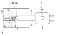
本実施形態の温度センサ1は、図1及び図2に示すように、一対のリードフレーム2と、一対のリードフレーム2の先端側に接続され感熱素子を有するセンサ部3と、一対のリードフレーム2の基端側に固定されて一対のリードフレーム2を保持する絶縁性の保持部4とを備えている。
なお、保持部4には、取付孔4aが形成されている。
なお、保持部4には、取付孔4aが形成されている。
上記センサ部3は、上面に一対のリードフレーム2が接着された絶縁性フィルム5と、絶縁性フィルム5の上面にサーミスタ材料で形成されたサーミスタ部6と、サーミスタ部6に接続された一対の対向電極7と、一端が一対の対向電極7に接続されていると共に他端が一対のリードフレーム2に接続され絶縁性フィルム5の上面に形成された一対の接続電極8とを備えている。
なお、本実施形態では、絶縁性フィルム5においてリードフレーム2が接着された面を上面として記載している。
なお、本実施形態では、絶縁性フィルム5においてリードフレーム2が接着された面を上面として記載している。
[規則91に基づく訂正 25.01.2017]
上記一対のリードフレーム2の先端側は絶縁性フィルム5の上下面のうち一方の側に湾曲しており、湾曲した部分Wにその湾曲形状に沿ってセンサ部3が湾曲して取り付けられている。すなわち、リードフレーム2の先端側の湾曲した部分Wは、延在方向に曲率を有して略円弧状に曲がっている。
本実施形態の温度センサ1は、図6及び図7に示すように、画像形成装置の定着ローラRの内側において定着ローラRの内周面に対してその周方向に沿ってセンサ部3の凸面側を接触させた状態で配置される。また、湾曲した部分Wの曲率半径は、定着ローラRの内周面の曲率半径よりも小さく設定されている。
なお、定着ローラR内には、センサ支持部材24が挿入状態で配置されており、保持部4の取付孔4aを用いて温度センサ1がセンサ支持部材24上にねじ止め等で設置されている。
上記一対のリードフレーム2の先端側は絶縁性フィルム5の上下面のうち一方の側に湾曲しており、湾曲した部分Wにその湾曲形状に沿ってセンサ部3が湾曲して取り付けられている。すなわち、リードフレーム2の先端側の湾曲した部分Wは、延在方向に曲率を有して略円弧状に曲がっている。
本実施形態の温度センサ1は、図6及び図7に示すように、画像形成装置の定着ローラRの内側において定着ローラRの内周面に対してその周方向に沿ってセンサ部3の凸面側を接触させた状態で配置される。また、湾曲した部分Wの曲率半径は、定着ローラRの内周面の曲率半径よりも小さく設定されている。
なお、定着ローラR内には、センサ支持部材24が挿入状態で配置されており、保持部4の取付孔4aを用いて温度センサ1がセンサ支持部材24上にねじ止め等で設置されている。
上記対向電極7は、サーミスタ部6の上に複数の櫛部7aを有して互いに対向してパターン形成されている。
上記センサ部3は、一対のリードフレーム2とセンサ部3とを上下から挟んで互いに接着された一対の絶縁性の保護テープ9A,9Bを備えている。
すなわち、絶縁性フィルム5、サーミスタ部6、対向電極7及び接続電極8によって感熱素子が構成されている。
上記センサ部3は、一対のリードフレーム2とセンサ部3とを上下から挟んで互いに接着された一対の絶縁性の保護テープ9A,9Bを備えている。
すなわち、絶縁性フィルム5、サーミスタ部6、対向電極7及び接続電極8によって感熱素子が構成されている。
一対のリードフレーム2の先端部2aは、サーミスタ部6よりも先端側で接続電極8と接続されていると共に、基端側に比べて互いに内側に幅広な形状とされている。
一対の上記接続電極8の先端側には、リードフレーム2の先端部2aに対応して幅広なパッド部8aが形成されている。これらのパッド部8aに、一対のリードフレーム2が、抵抗溶接、スポット溶接、ハンダ材又は導電性樹脂接着剤等の接着剤により接着されている。
なお、センサ部3では、パッド部8aを除いた接続電極8,サーミスタ部6及び対向電極7を覆う絶縁性の保護膜10が絶縁性フィルム5上に形成されている。
一対の上記接続電極8の先端側には、リードフレーム2の先端部2aに対応して幅広なパッド部8aが形成されている。これらのパッド部8aに、一対のリードフレーム2が、抵抗溶接、スポット溶接、ハンダ材又は導電性樹脂接着剤等の接着剤により接着されている。
なお、センサ部3では、パッド部8aを除いた接続電極8,サーミスタ部6及び対向電極7を覆う絶縁性の保護膜10が絶縁性フィルム5上に形成されている。
上記絶縁性フィルム5は、略長方形状とされ、例えば厚さ7.5~125μmのポリイミド樹脂シートで帯状に形成されている。なお、絶縁性フィルム5としては、他にPET:ポリエチレンテレフタレート,PEN:ポリエチレンナフタレート等でも作製できるが、定着ローラの温度測定用としては、最高使用温度が230℃と高いためポリイミドフィルムが望ましい。
上記サーミスタ部6は、パターン形成された薄膜サーミスタであり、絶縁性フィルム5の基端側に配され、例えばTiAlNのサーミスタ材料で形成されている。特に、サーミスタ部6は、一般式:TixAlyNz(0.70≦y/(x+y)≦0.95、0.4≦z≦0.5、x+y+z=1)で示される金属窒化物からなり、その結晶構造が、六方晶系のウルツ鉱型の単相である。
このサーミスタ部6も、湾曲した部分Wに沿って湾曲している。
このサーミスタ部6も、湾曲した部分Wに沿って湾曲している。
上記接続電極8及び対向電極7は、サーミスタ部6上に形成された膜厚5~100nmのCr又はNiCrの接合層と、該接合層上にAu等の貴金属で膜厚50~1000nmで形成された電極層とを有している。
一対の対向電極7は、互いに対向状態に配されて交互に櫛部7aが並んだ櫛型パターンとされている。
一対の対向電極7は、互いに対向状態に配されて交互に櫛部7aが並んだ櫛型パターンとされている。
なお、櫛部7aは、リードフレーム2の延在方向に沿って延在している。すなわち、リードフレーム2の延在方向に曲率を有して湾曲させるため、サーミスタ部6にも同方向に曲げ応力が加わる。このとき、櫛部7aが同方向に延在しているため、サーミスタ部6を補強することになり、クラックの発生を抑制することができる。
上記保護膜10は、絶縁性樹脂膜等であり、例えば厚さ20μmのポリイミド膜が採用される。
上記保護テープ9A,9Bは、テフロン(登録商標)等のフッ化炭素樹脂で形成されている。
上記保護膜10は、絶縁性樹脂膜等であり、例えば厚さ20μmのポリイミド膜が採用される。
上記保護テープ9A,9Bは、テフロン(登録商標)等のフッ化炭素樹脂で形成されている。
この温度センサ1の製造方法について、図1から図4を参照して以下に説明する。
本実施形態の温度センサ1の製造方法は、絶縁性フィルム5の表面にサーミスタ部6をパターン形成するサーミスタ部形成工程と、互いに対向した一対の対向電極7をサーミスタ部6上に配して絶縁性フィルム5の表面に一対の接続電極8をパターン形成する電極形成工程と、絶縁性フィルム5上に保護膜10を形成する保護膜形成工程と、センサ部3にリードフレーム2を固定するリードフレーム固定工程と、リードフレーム2及びセンサ部3を上下から保護テープ9A,9Bで挟んで互いに接着する保護テープ接着工程と、リードフレーム2の先端側を曲げ加工し湾曲させる曲げ工程とを有している。
本実施形態の温度センサ1の製造方法は、絶縁性フィルム5の表面にサーミスタ部6をパターン形成するサーミスタ部形成工程と、互いに対向した一対の対向電極7をサーミスタ部6上に配して絶縁性フィルム5の表面に一対の接続電極8をパターン形成する電極形成工程と、絶縁性フィルム5上に保護膜10を形成する保護膜形成工程と、センサ部3にリードフレーム2を固定するリードフレーム固定工程と、リードフレーム2及びセンサ部3を上下から保護テープ9A,9Bで挟んで互いに接着する保護テープ接着工程と、リードフレーム2の先端側を曲げ加工し湾曲させる曲げ工程とを有している。
より具体的な製造方法の例としては、厚さ50μmのポリイミドフィルムの絶縁性フィルム5上(一方の面上)に、Ti-Al合金スパッタリングターゲットを用い、窒素含有雰囲気中で反応性スパッタ法にて、TixAlyNz(x=0.09、y=0.43、z=0.48)のサーミスタ膜を膜厚200nmで形成する。その時のスパッタ条件は、到達真空度5×10⁻⁶Pa、スパッタガス圧0.4Pa、ターゲット投入電力(出力)200Wで、Arガス+窒素ガスの混合ガス雰囲気下において、窒素ガス分率を20%で作製する。
成膜したサーミスタ膜の上にレジスト液をスピンコーターで塗布した後、110℃で1分30秒プリベークを行い、露光装置で感光後、現像液で不要部分を除去し、さらに150℃で5分のポストベークにてパターニングを行う。その後、不要なTixAlyNzのサーミスタ膜を市販のTiエッチャントでウェットエッチングを行い、図4の(a)に示すように、レジスト剥離にて所望の形状のサーミスタ部6にする。
次に、サーミスタ部6及び絶縁性フィルム5上に、スパッタ法にて、Cr膜の接合層を膜厚20nm形成する。さらに、この接合層上に、スパッタ法にてAu膜の電極層を膜厚200nm形成する。
次に、成膜した電極層の上にレジスト液をスピンコーターで塗布した後、110℃で1分30秒プリベークを行い、露光装置で感光後、現像液で不要部分を除去し、150℃で5分のポストベークにてパターニングを行う。その後、不要な電極部分を市販のAuエッチャント及びCrエッチャントの順番でウェットエッチングを行い、図4の(b)に示すように、レジスト剥離にて所望の対向電極7及び接続電極8を形成する。
次に、成膜した電極層の上にレジスト液をスピンコーターで塗布した後、110℃で1分30秒プリベークを行い、露光装置で感光後、現像液で不要部分を除去し、150℃で5分のポストベークにてパターニングを行う。その後、不要な電極部分を市販のAuエッチャント及びCrエッチャントの順番でウェットエッチングを行い、図4の(b)に示すように、レジスト剥離にて所望の対向電極7及び接続電極8を形成する。
さらに、絶縁性フィルム5の表面にポリイミドワニスを印刷法により所定部分に塗布して、180℃、30分でキュアを行い、20μm厚のポリイミド保護膜10を形成する。
次に、絶縁性フィルム5の表面にポリイミドワニスを印刷法により所定部分に塗布して、180℃、30分でキュアを行い、図3に示すように、20μm厚のポリイミド保護膜10を形成する。
次に、絶縁性フィルム5の表面にポリイミドワニスを印刷法により所定部分に塗布して、180℃、30分でキュアを行い、図3に示すように、20μm厚のポリイミド保護膜10を形成する。
次に、パッド部8aとなる幅広な領域にNiめっきを施して、パッド部8aを形成する。
なお、保護テープ9A,9Bで挟む前の複数のセンサ部3を同時に作製する場合、絶縁性フィルム5の大判シートに複数のサーミスタ部6、対向電極7、接続電極8、保護膜10及びパッド部8aを上述のように形成した後に、大判シートから各センサ部3に切断する。
なお、保護テープ9A,9Bで挟む前の複数のセンサ部3を同時に作製する場合、絶縁性フィルム5の大判シートに複数のサーミスタ部6、対向電極7、接続電極8、保護膜10及びパッド部8aを上述のように形成した後に、大判シートから各センサ部3に切断する。
次に、図1に示すように、一対のパッド部8aに直線状の一対のリードフレーム2の先端部2aを抵抗溶接等により接着し、リードフレーム2をセンサ部3に固定する。
さらに、センサ部3とリードフレーム2の先端側とを上下から一対の保護テープ9A,9Bで挟んで、保護テープ9A,9Bの互いの両側部をプレスして接着する。
次に、固定した一対のリードフレーム2の先端側を、絶縁性フィルム5を凸面側に配して曲げ加工し湾曲させる。これにより、図1に示すように、温度センサ1が作製される。
なお、リードフレーム2の先端側を予め曲げ加工した後に、湾曲した部分Wに湾曲させたセンサ部3を抵抗溶接等により取り付けても構わない。
さらに、センサ部3とリードフレーム2の先端側とを上下から一対の保護テープ9A,9Bで挟んで、保護テープ9A,9Bの互いの両側部をプレスして接着する。
次に、固定した一対のリードフレーム2の先端側を、絶縁性フィルム5を凸面側に配して曲げ加工し湾曲させる。これにより、図1に示すように、温度センサ1が作製される。
なお、リードフレーム2の先端側を予め曲げ加工した後に、湾曲した部分Wに湾曲させたセンサ部3を抵抗溶接等により取り付けても構わない。
このように本実施形態の温度センサ1では、一対のリードフレーム2の先端側が絶縁性フィルム5の上下面のうち一方の側に湾曲しており、湾曲した部分Wにその湾曲形状に沿ってセンサ部3が湾曲して取り付けられているので、従来の直線状のリードフレームを押し当てて湾曲させる場合に比べて、予め湾曲形状を有しているので、極めて弱い押し付け圧力であっても測定対象物の凹曲面(定着ローラRの内周面等)に面接触させることが可能である。
[規則91に基づく訂正 25.01.2017]
また、この温度センサ1では、サーミスタ部6が、パターン形成された薄膜サーミスタであり、湾曲した部分Wに沿って湾曲しているので、薄膜サーミスタのサーミスタ部6も湾曲することで、センサ部3全体がより滑らかにカーブし、測定対象物に対してさらに良好な面接触をさせることが可能になる。
すなわち、絶縁性フィルム5上に薄膜サーミスタのサーミスタ部6をパターン形成したフレキシブルなセンサ部3を、リードフレーム2の湾曲した部分に取り付けるため、センサ部3及びサーミスタ部6自体が容易に湾曲し、予め湾曲した状態のまま測定対象物に面接触させることができる。
また、湾曲した部分Wの曲率半径が、定着ローラRの内周面の曲率半径よりも小さく設定されているので、リードフレーム2の先端が定着ローラRの内周面に当たらず、先端で定着ローラRを傷つけるおそれがない。
また、この温度センサ1では、サーミスタ部6が、パターン形成された薄膜サーミスタであり、湾曲した部分Wに沿って湾曲しているので、薄膜サーミスタのサーミスタ部6も湾曲することで、センサ部3全体がより滑らかにカーブし、測定対象物に対してさらに良好な面接触をさせることが可能になる。
すなわち、絶縁性フィルム5上に薄膜サーミスタのサーミスタ部6をパターン形成したフレキシブルなセンサ部3を、リードフレーム2の湾曲した部分に取り付けるため、センサ部3及びサーミスタ部6自体が容易に湾曲し、予め湾曲した状態のまま測定対象物に面接触させることができる。
また、湾曲した部分Wの曲率半径が、定着ローラRの内周面の曲率半径よりも小さく設定されているので、リードフレーム2の先端が定着ローラRの内周面に当たらず、先端で定着ローラRを傷つけるおそれがない。
さらに、本実施形態の温度センサ1の製造方法では、固定した一対のリードフレーム2の先端側を、前記センサ部と共に曲げ加工し湾曲させる曲げ工程を有しているので、絶縁性フィルム5上にサーミスタ部6を形成したセンサ部3をリードフレーム2と共に柔軟にかつ同時に湾曲させることができる。
次に、本発明に係る温度センサの第2実施形態について、図8を参照して以下に説明する。なお、以下の実施形態の説明において、上記実施形態において説明した同一の構成要素には同一の符号を付し、その説明は省略する。
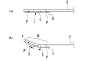
第2実施形態と第1実施形態との異なる点は、第1実施形態では、一対のリードフレームの先端部2aと接続電極8のパッド部8aとを溶接等で固定するのに対し、第2実施形態の温度センサでは、図8に示すように、サーミスタ部6よりも先端側と基端側とで一対のリードフレーム2を一対の接続電極8に溶接する点である。
すなわち、第2実施形態では、図8の(a)に示すように、一対のパッド部8aと直線状の一対のリードフレーム2の先端部2aとを抵抗溶接すると共に、一対の接続電極8の基端側と一対のリードフレーム2の中間部分とを抵抗溶接する。このように、リードフレーム2と接続電極8とを、サーミスタ部6の前後の少なくとも2カ所の溶接部分Pで溶接し、固定する。
さらに、図8の(b)に示すように、固定した一対のリードフレーム2の先端側を、絶縁性フィルム5を凸面側に配して曲げ加工し湾曲させる。なお、図8の(b)においては、保護テープ9A,9Bの図示を省略している。
さらに、図8の(b)に示すように、固定した一対のリードフレーム2の先端側を、絶縁性フィルム5を凸面側に配して曲げ加工し湾曲させる。なお、図8の(b)においては、保護テープ9A,9Bの図示を省略している。
このように第2実施形態の温度センサ及びその製造方法では、固定工程において、サーミスタ部6よりも先端側と基端側とで一対のリードフレーム2を一対の接続電極8に溶接するので、曲げ工程でリードフレーム2と共に湾曲させられた際に、前後の溶接部分Pの間で引っ張られ、センサ部3が緩まずにリードフレーム2に密着した状態で湾曲形状が得られる。
[規則91に基づく訂正 25.01.2017]
次に、第3実施形態と第1実施形態との異なる点は、第1実施形態では、リードフレーム2及びセンサ部3が定着ローラRの内周面の曲率半径よりも小さい一定の曲率半径で湾曲しているのに対し、第3実施形態の温度センサ31では、図9に示すように、湾曲した部分Wが、定着ローラRの内周面に接触する部分W1と接触する部分W1よりも先端側W2とを少なくとも有し、接触する部分W1の曲率半径に比べて、先端側W2の曲率半径が小さく設定されている点である。すなわち、第3実施形態では、湾曲した部分Wが、少なくとも2つの異なる曲率半径で湾曲した部分W1,W2の組み合わせで構成されている。
次に、第3実施形態と第1実施形態との異なる点は、第1実施形態では、リードフレーム2及びセンサ部3が定着ローラRの内周面の曲率半径よりも小さい一定の曲率半径で湾曲しているのに対し、第3実施形態の温度センサ31では、図9に示すように、湾曲した部分Wが、定着ローラRの内周面に接触する部分W1と接触する部分W1よりも先端側W2とを少なくとも有し、接触する部分W1の曲率半径に比べて、先端側W2の曲率半径が小さく設定されている点である。すなわち、第3実施形態では、湾曲した部分Wが、少なくとも2つの異なる曲率半径で湾曲した部分W1,W2の組み合わせで構成されている。
[規則91に基づく訂正 25.01.2017]
第3実施形態では、例えば定着ローラRの内周面に接触する部分W1の曲率半径を定着ローラRの内周面の曲率半径と同じかやや大きく設定すると共に先端側W2の曲率半径を定着ローラRの内周面の曲率半径よりも小さくする。この場合、弱い押し付け圧でもセンサ部3が定着ローラRの内周面に対して広く面接触すると共に、先端が定着ローラRの内周面に当接して傷つけることを防止できる。
なお、接触する部分W1と先端側W2との曲率半径が変わる接続部分については、漸次曲率半径が変わるようにするか、もしくは互いの接線を合わせるように設定されている。少なくとも上記接続部分で折り曲げた角部が生じないように設定することが好ましい。
このように第3実施形態の温度センサ31では、定着ローラRの内周面に接触する部分W1の曲率半径に比べて、先端側W2の曲率半径が小さく設定されているので、接触する部分W1の広い面接触と先端側W2の非接触とを両立させることができる。
第3実施形態では、例えば定着ローラRの内周面に接触する部分W1の曲率半径を定着ローラRの内周面の曲率半径と同じかやや大きく設定すると共に先端側W2の曲率半径を定着ローラRの内周面の曲率半径よりも小さくする。この場合、弱い押し付け圧でもセンサ部3が定着ローラRの内周面に対して広く面接触すると共に、先端が定着ローラRの内周面に当接して傷つけることを防止できる。
なお、接触する部分W1と先端側W2との曲率半径が変わる接続部分については、漸次曲率半径が変わるようにするか、もしくは互いの接線を合わせるように設定されている。少なくとも上記接続部分で折り曲げた角部が生じないように設定することが好ましい。
このように第3実施形態の温度センサ31では、定着ローラRの内周面に接触する部分W1の曲率半径に比べて、先端側W2の曲率半径が小さく設定されているので、接触する部分W1の広い面接触と先端側W2の非接触とを両立させることができる。
なお、本発明の技術範囲は上記各実施形態に限定されるものではなく、本発明の趣旨を逸脱しない範囲において種々の変更を加えることが可能である。
1,31…温度センサ、2…リードフレーム、3…センサ部、4…保持部、5…絶縁性フィルム、6…サーミスタ部、7…対向電極、7a…櫛部、8…接続電極、R…定着ローラ、W…湾曲した部分、W1…接触する部分、W2…接触する部分よりも先端側
Claims (6)
- 一対のリードフレームと、前記一対のリードフレームの先端側に接続され感熱素子を有するセンサ部と、前記一対のリードフレームの基端側に固定されて前記一対のリードフレームを保持する絶縁性の保持部とを備え、
前記センサ部が、上面に前記一対のリードフレームが接着された絶縁性フィルムと、
前記絶縁性フィルムの上面にサーミスタ材料で形成されたサーミスタ部と、
前記サーミスタ部に接続された一対の対向電極と、
一端が前記一対の対向電極に接続されていると共に他端が前記一対のリードフレームに接続され前記絶縁性フィルムの上面に形成された一対の接続電極とを備え、
前記一対のリードフレームの先端側が前記絶縁性フィルムの上下面のうち一方の側に湾曲しており、前記湾曲した部分にその湾曲形状に沿って前記センサ部が湾曲して取り付けられていることを特徴とする温度センサ。 - 請求項1に記載の温度センサにおいて、
前記サーミスタ部が、パターン形成された薄膜サーミスタであり、前記湾曲した部分に沿って湾曲していることを特徴とする温度センサ。 - [規則91に基づく訂正 25.01.2017]
請求項1に記載の温度センサにおいて、
画像形成装置の定着ローラの内側において前記定着ローラの内周面に対してその周方向に沿って前記センサ部の凸面側を接触させた状態で配置され、
前記湾曲した部分の曲率半径が、前記定着ローラの内周面の曲率半径よりも小さく設定されていることを特徴とする温度センサ。 - [規則91に基づく訂正 25.01.2017]
請求項1に記載の温度センサにおいて、
画像形成装置の定着ローラの内側において前記定着ローラの内周面に対してその周方向に沿って前記センサ部の凸面側を接触させた状態で配置され、
前記湾曲した部分が、前記定着ローラの内周面に接触する部分と前記接触する部分よりも先端側とを少なくとも有し、前記接触する部分の曲率半径に比べて、前記接触する部分よりも先端側の曲率半径が小さく設定されていることを特徴とする温度センサ。 - 請求項1に記載の温度センサを製造する方法であって、
直線状の一対のリードフレームを前記センサ部に固定する固定工程と、
固定した前記一対のリードフレームの先端側を、前記センサ部と共に曲げ加工し湾曲させる曲げ工程とを有していることを特徴とする温度センサの製造方法。 - 請求項5に記載の温度センサの製造方法において、
前記固定工程において、前記サーミスタ部よりも先端側と基端側とで前記一対のリードフレームを前記一対の接続電極に溶接し、
前記曲げ工程において、前記絶縁性フィルムを凸面側に配して曲げ加工し湾曲させることを特徴とする温度センサの製造方法。
Applications Claiming Priority (2)
| Application Number | Priority Date | Filing Date | Title |
|---|---|---|---|
| JP2015220263A JP6734559B2 (ja) | 2015-11-10 | 2015-11-10 | 温度センサ及びその製造方法 |
| JP2015-220263 | 2015-11-10 |
Publications (1)
| Publication Number | Publication Date |
|---|---|
| WO2017081832A1 true WO2017081832A1 (ja) | 2017-05-18 |
Family
ID=58694995
Family Applications (1)
| Application Number | Title | Priority Date | Filing Date |
|---|---|---|---|
| PCT/JP2016/003895 Ceased WO2017081832A1 (ja) | 2015-11-10 | 2016-08-26 | 温度センサ及びその製造方法 |
Country Status (2)
| Country | Link |
|---|---|
| JP (1) | JP6734559B2 (ja) |
| WO (1) | WO2017081832A1 (ja) |
Cited By (1)
| Publication number | Priority date | Publication date | Assignee | Title |
|---|---|---|---|---|
| CN112219091A (zh) * | 2018-06-08 | 2021-01-12 | 恩德斯+豪斯流量技术股份有限公司 | 测量装置 |
Citations (4)
| Publication number | Priority date | Publication date | Assignee | Title |
|---|---|---|---|---|
| JPS5677731A (en) * | 1979-11-30 | 1981-06-26 | Ishizuka Denshi Kk | Production of temperature sensor |
| JP2003307966A (ja) * | 2002-04-16 | 2003-10-31 | Ishizuka Electronics Corp | 定着装置及び定着用温度センサ |
| JP2014149154A (ja) * | 2013-01-31 | 2014-08-21 | Mitsubishi Materials Corp | 温度センサ |
| JP2014182086A (ja) * | 2013-03-21 | 2014-09-29 | Mitsubishi Materials Corp | 温度センサ |
Family Cites Families (4)
| Publication number | Priority date | Publication date | Assignee | Title |
|---|---|---|---|---|
| JP3434010B2 (ja) * | 1994-04-19 | 2003-08-04 | 石塚電子株式会社 | 温度センサ |
| JP4193429B2 (ja) * | 2002-07-08 | 2008-12-10 | 富士ゼロックス株式会社 | 画像形成装置 |
| JP5248356B2 (ja) * | 2009-02-02 | 2013-07-31 | 矢崎総業株式会社 | 温度検出部構造 |
| JP5763805B1 (ja) * | 2014-04-28 | 2015-08-12 | 株式会社芝浦電子 | 温度センサ |
-
2015
- 2015-11-10 JP JP2015220263A patent/JP6734559B2/ja active Active
-
2016
- 2016-08-26 WO PCT/JP2016/003895 patent/WO2017081832A1/ja not_active Ceased
Patent Citations (4)
| Publication number | Priority date | Publication date | Assignee | Title |
|---|---|---|---|---|
| JPS5677731A (en) * | 1979-11-30 | 1981-06-26 | Ishizuka Denshi Kk | Production of temperature sensor |
| JP2003307966A (ja) * | 2002-04-16 | 2003-10-31 | Ishizuka Electronics Corp | 定着装置及び定着用温度センサ |
| JP2014149154A (ja) * | 2013-01-31 | 2014-08-21 | Mitsubishi Materials Corp | 温度センサ |
| JP2014182086A (ja) * | 2013-03-21 | 2014-09-29 | Mitsubishi Materials Corp | 温度センサ |
Cited By (1)
| Publication number | Priority date | Publication date | Assignee | Title |
|---|---|---|---|---|
| CN112219091A (zh) * | 2018-06-08 | 2021-01-12 | 恩德斯+豪斯流量技术股份有限公司 | 测量装置 |
Also Published As
| Publication number | Publication date |
|---|---|
| JP6734559B2 (ja) | 2020-08-05 |
| JP2017090235A (ja) | 2017-05-25 |
Similar Documents
| Publication | Publication Date | Title |
|---|---|---|
| EP1847799B1 (en) | Strain gauge for measuring large strains | |
| JP6497133B2 (ja) | 温度センサ | |
| CN105899921B (zh) | 非接触式温度传感器 | |
| JP2000074752A (ja) | 温度センサ | |
| JP6617909B2 (ja) | 温度センサ | |
| JPH0868699A (ja) | サーミスタセンサ | |
| JP6603991B2 (ja) | 温度センサ | |
| JP6583073B2 (ja) | 温度センサ | |
| JP3756607B2 (ja) | 温度センサ | |
| WO2017081832A1 (ja) | 温度センサ及びその製造方法 | |
| JP2000312070A (ja) | 電極端子の接続方法 | |
| JP2017053782A (ja) | 温度センサ | |
| JP6684435B2 (ja) | 温度センサ | |
| WO2023276518A1 (ja) | 温度センサー | |
| JP6641770B2 (ja) | 温度センサ | |
| JP2017026415A (ja) | 温度センサ | |
| JP2017166939A (ja) | 温度センサ | |
| JP6772843B2 (ja) | 温度センサ | |
| JP6460376B2 (ja) | 温度センサ及びその製造方法 | |
| JP3380324B2 (ja) | 温度センサ | |
| JP2016090262A (ja) | 温度センサ及びその製造方法 | |
| JP2018132497A (ja) | 温度センサ | |
| JP2014169874A (ja) | 温度センサ | |
| JP2024141588A (ja) | 金属配線と無機酸化物配線との接合構造 | |
| JP2016050786A (ja) | 温度センサ |
Legal Events
| Date | Code | Title | Description |
|---|---|---|---|
| 121 | Ep: the epo has been informed by wipo that ep was designated in this application |
Ref document number: 16863799 Country of ref document: EP Kind code of ref document: A1 |
|
| NENP | Non-entry into the national phase |
Ref country code: DE |
|
| 122 | Ep: pct application non-entry in european phase |
Ref document number: 16863799 Country of ref document: EP Kind code of ref document: A1 |