WO2017073554A1 - タービン分析装置、タービン分析方法およびプログラム - Google Patents
タービン分析装置、タービン分析方法およびプログラム Download PDFInfo
- Publication number
- WO2017073554A1 WO2017073554A1 PCT/JP2016/081559 JP2016081559W WO2017073554A1 WO 2017073554 A1 WO2017073554 A1 WO 2017073554A1 JP 2016081559 W JP2016081559 W JP 2016081559W WO 2017073554 A1 WO2017073554 A1 WO 2017073554A1
- Authority
- WO
- WIPO (PCT)
- Prior art keywords
- turbine
- load
- time
- unit
- history
- Prior art date
- Legal status (The legal status is an assumption and is not a legal conclusion. Google has not performed a legal analysis and makes no representation as to the accuracy of the status listed.)
- Ceased
Links
Images


Classifications
-
- F—MECHANICAL ENGINEERING; LIGHTING; HEATING; WEAPONS; BLASTING
- F02—COMBUSTION ENGINES; HOT-GAS OR COMBUSTION-PRODUCT ENGINE PLANTS
- F02C—GAS-TURBINE PLANTS; AIR INTAKES FOR JET-PROPULSION PLANTS; CONTROLLING FUEL SUPPLY IN AIR-BREATHING JET-PROPULSION PLANTS
- F02C9/00—Controlling gas-turbine plants; Controlling fuel supply in air- breathing jet-propulsion plants
- F02C9/26—Control of fuel supply
- F02C9/28—Regulating systems responsive to plant or ambient parameters, e.g. temperature, pressure, rotor speed
-
- F—MECHANICAL ENGINEERING; LIGHTING; HEATING; WEAPONS; BLASTING
- F01—MACHINES OR ENGINES IN GENERAL; ENGINE PLANTS IN GENERAL; STEAM ENGINES
- F01D—NON-POSITIVE DISPLACEMENT MACHINES OR ENGINES, e.g. STEAM TURBINES
- F01D21/00—Shutting-down of machines or engines, e.g. in emergency; Regulating, controlling, or safety means not otherwise provided for
- F01D21/003—Arrangements for testing or measuring
-
- F—MECHANICAL ENGINEERING; LIGHTING; HEATING; WEAPONS; BLASTING
- F01—MACHINES OR ENGINES IN GENERAL; ENGINE PLANTS IN GENERAL; STEAM ENGINES
- F01D—NON-POSITIVE DISPLACEMENT MACHINES OR ENGINES, e.g. STEAM TURBINES
- F01D25/00—Component parts, details, or accessories, not provided for in, or of interest apart from, other groups
-
- F—MECHANICAL ENGINEERING; LIGHTING; HEATING; WEAPONS; BLASTING
- F01—MACHINES OR ENGINES IN GENERAL; ENGINE PLANTS IN GENERAL; STEAM ENGINES
- F01D—NON-POSITIVE DISPLACEMENT MACHINES OR ENGINES, e.g. STEAM TURBINES
- F01D25/00—Component parts, details, or accessories, not provided for in, or of interest apart from, other groups
- F01D25/005—Selecting particular materials
-
- F—MECHANICAL ENGINEERING; LIGHTING; HEATING; WEAPONS; BLASTING
- F02—COMBUSTION ENGINES; HOT-GAS OR COMBUSTION-PRODUCT ENGINE PLANTS
- F02C—GAS-TURBINE PLANTS; AIR INTAKES FOR JET-PROPULSION PLANTS; CONTROLLING FUEL SUPPLY IN AIR-BREATHING JET-PROPULSION PLANTS
- F02C3/00—Gas-turbine plants characterised by the use of combustion products as the working fluid
-
- F—MECHANICAL ENGINEERING; LIGHTING; HEATING; WEAPONS; BLASTING
- F02—COMBUSTION ENGINES; HOT-GAS OR COMBUSTION-PRODUCT ENGINE PLANTS
- F02C—GAS-TURBINE PLANTS; AIR INTAKES FOR JET-PROPULSION PLANTS; CONTROLLING FUEL SUPPLY IN AIR-BREATHING JET-PROPULSION PLANTS
- F02C7/00—Features, components parts, details or accessories, not provided for in, or of interest apart form groups F02C1/00 - F02C6/00; Air intakes for jet-propulsion plants
-
- F—MECHANICAL ENGINEERING; LIGHTING; HEATING; WEAPONS; BLASTING
- F02—COMBUSTION ENGINES; HOT-GAS OR COMBUSTION-PRODUCT ENGINE PLANTS
- F02C—GAS-TURBINE PLANTS; AIR INTAKES FOR JET-PROPULSION PLANTS; CONTROLLING FUEL SUPPLY IN AIR-BREATHING JET-PROPULSION PLANTS
- F02C7/00—Features, components parts, details or accessories, not provided for in, or of interest apart form groups F02C1/00 - F02C6/00; Air intakes for jet-propulsion plants
- F02C7/36—Power transmission arrangements between the different shafts of the gas turbine plant, or between the gas-turbine plant and the power user
-
- G—PHYSICS
- G01—MEASURING; TESTING
- G01M—TESTING STATIC OR DYNAMIC BALANCE OF MACHINES OR STRUCTURES; TESTING OF STRUCTURES OR APPARATUS, NOT OTHERWISE PROVIDED FOR
- G01M15/00—Testing of engines
- G01M15/14—Testing gas-turbine engines or jet-propulsion engines
-
- G—PHYSICS
- G01—MEASURING; TESTING
- G01M—TESTING STATIC OR DYNAMIC BALANCE OF MACHINES OR STRUCTURES; TESTING OF STRUCTURES OR APPARATUS, NOT OTHERWISE PROVIDED FOR
- G01M99/00—Subject matter not provided for in other groups of this subclass
-
- F—MECHANICAL ENGINEERING; LIGHTING; HEATING; WEAPONS; BLASTING
- F05—INDEXING SCHEMES RELATING TO ENGINES OR PUMPS IN VARIOUS SUBCLASSES OF CLASSES F01-F04
- F05D—INDEXING SCHEME FOR ASPECTS RELATING TO NON-POSITIVE-DISPLACEMENT MACHINES OR ENGINES, GAS-TURBINES OR JET-PROPULSION PLANTS
- F05D2220/00—Application
- F05D2220/30—Application in turbines
- F05D2220/32—Application in turbines in gas turbines
-
- F—MECHANICAL ENGINEERING; LIGHTING; HEATING; WEAPONS; BLASTING
- F05—INDEXING SCHEMES RELATING TO ENGINES OR PUMPS IN VARIOUS SUBCLASSES OF CLASSES F01-F04
- F05D—INDEXING SCHEME FOR ASPECTS RELATING TO NON-POSITIVE-DISPLACEMENT MACHINES OR ENGINES, GAS-TURBINES OR JET-PROPULSION PLANTS
- F05D2260/00—Function
- F05D2260/80—Diagnostics
-
- F—MECHANICAL ENGINEERING; LIGHTING; HEATING; WEAPONS; BLASTING
- F05—INDEXING SCHEMES RELATING TO ENGINES OR PUMPS IN VARIOUS SUBCLASSES OF CLASSES F01-F04
- F05D—INDEXING SCHEME FOR ASPECTS RELATING TO NON-POSITIVE-DISPLACEMENT MACHINES OR ENGINES, GAS-TURBINES OR JET-PROPULSION PLANTS
- F05D2260/00—Function
- F05D2260/81—Modelling or simulation
-
- F—MECHANICAL ENGINEERING; LIGHTING; HEATING; WEAPONS; BLASTING
- F05—INDEXING SCHEMES RELATING TO ENGINES OR PUMPS IN VARIOUS SUBCLASSES OF CLASSES F01-F04
- F05D—INDEXING SCHEME FOR ASPECTS RELATING TO NON-POSITIVE-DISPLACEMENT MACHINES OR ENGINES, GAS-TURBINES OR JET-PROPULSION PLANTS
- F05D2260/00—Function
- F05D2260/82—Forecasts
Definitions
- the present invention relates to a turbine analysis device, a turbine analysis method, and a program.
- Patent Document 1 in the rotation plan for a high-temperature gas turbine component, if the remaining life of the high-temperature component is less than the next scheduled operation period, the self-inspection timing is changed, so that the remaining time when the high-temperature component is discarded A technique for minimizing the lifetime is disclosed.
- An object of the present invention is to provide a turbine analysis device, a turbine analysis method, and a program for appropriately managing the life of a turbine according to a load.
- the turbine analyzer specifies a state quantity acquisition unit that acquires the state quantity of the turbine including the temperature of the turbine, and identifies a load history of the turbine based on the state quantity.
- the load specifying unit specifies a temperature history variable indicating a temperature history of the turbine based on the state quantity
- the load / time calculation unit calculates a relationship between the load of the turbine and the operable time when the turbine is operated at the load based on the design life of the turbine and the temperature history variable.
- the turbine analyzer according to the first or second aspect further includes a time specifying unit that specifies a time during which the operation of the turbine should be continued, and the load / time calculating unit However, the load capable of continuing the operation of the turbine for the time specified by the time specifying unit is calculated.
- the turbine analyzer determines whether or not the operation can be continued until a predetermined inspection time when the turbine operates at a predetermined load.
- the availability determining unit further includes the time specifying unit specifying the time from the current time to the inspection time as the time to continue the operation of the turbine, and when the operation determining unit determines that the operation cannot be continued
- the load / time calculation unit calculates a load capable of continuing the operation of the turbine during the time specified by the time specifying unit.
- the turbine analyzer includes a generated power amount prediction unit that predicts the amount of power to be generated by the plurality of turbines, and the load / time calculation.
- An operation plan generation unit that generates operation plans for the plurality of turbines based on the load calculated by the unit and the electric energy predicted by the generated electric energy prediction unit.
- the turbine analysis device further includes a load input unit that receives an input of a load for operating the turbine, and the load / time calculation unit includes: The operable time of the turbine with the input load is calculated.
- the turbine analysis method includes a step of acquiring a state quantity of the turbine including a temperature of the turbine, and a step of specifying a load history of the turbine based on the state quantity. And calculating a relationship between the load of the turbine and the operable time when the turbine is operated at the load based on the design life of the turbine and the identified history of the load.
- the program specifies a history of a load of the turbine based on the state quantity acquisition unit that acquires a state quantity of the turbine including a turbine temperature, and the state quantity. And calculating the relationship between the load of the turbine and the operable time when the turbine is operated with the load based on the design life of the turbine and the history of the load specified by the load specification unit Function as a load / time calculation unit.
- the turbine analyzer calculates the relationship between the turbine load and the operable time based on the turbine load history. Thereby, the turbine analyzer can appropriately manage the life of the turbine according to the load.
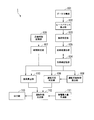
- FIG. 1 is a schematic block diagram illustrating the configuration of the planning device according to the first embodiment.
- the turbine analyzer 1 according to the first embodiment generates an operation plan for a plurality of turbines.
- the turbine operation plan according to the first embodiment is information indicating a load related to the operation of each turbine.
- the turbine analysis apparatus 1 according to the first embodiment includes a data collection unit 101, a heat balance calculation unit 102, a load specification unit 103, a remaining life storage unit 104, a remaining life calculation unit 105, an inspection time storage unit 106, and a time specification unit. 107, a drivable time calculation unit 108, a drivability determination unit 109, a load calculation unit 110, a generated power amount prediction unit 111, a driving plan generation unit 112, and an output unit 113.
- the data collection unit 101 collects turbine operation data in real time from a power plant owned by a customer. Specifically, the data collection unit 101 collects operation data from a sensor provided in the turbine every predetermined collection period (for example, 5 minutes). The collection period is a period that is so short that the immediacy of monitoring is not lost. Examples of operational data include flow rate, pressure, temperature, vibration, and other state quantities.
- the data collection unit 101 is an example of a state quantity acquisition unit that acquires a turbine state quantity.
- the heat balance calculation unit 102 calculates the heat balance of the turbine based on the operation data collected by the data collection unit 101.
- Heat balance is the temperature, pressure, enthalpy, flow rate, and other state quantities at each of the components attached to the turbine.
- the heat balance calculation unit 102 calculates the heat balance by simulation based on the operation data. Examples of simulation methods for calculating the heat balance include FEM (Finite Element Fluid Method) and CFD (Computational Fluid Dynamics).
- the heat balance calculation unit 102 is an example of a state quantity acquisition unit that acquires a turbine state quantity.
- Load specifying unit 103 based on the heat balance of the heat balance calculation unit 102 has calculated, to calculate the LMP (Larson-Miller Parameter) value L c indicating a degradation amount of each component in the immediate vicinity of the collection period.
- the LMP value L c is a parameter obtained by the following equation (1).
- T c indicates the thermodynamic temperature of the part.
- the thermodynamic temperature is equivalent to a value obtained by adding 273.15 to the Celsius temperature.
- the temperature of the component is specified by the heat balance calculated by the heat balance calculation unit 102.
- t c indicates the operating time of the turbine at the temperature T c . That is, the time t c is equal to the collection cycle by the data collection unit 101.
- C is a constant determined by the material of the part. For example, if the material of the part is low carbon steel or chrome molybdenum steel, the constant C may be 20. For example, when the material of the component is stainless steel, the constant C may be 15.
- the LMP value is a parameter specified from the temperature of the part and the operation time.
- the LMP value is an example of a temperature history variable related to a temperature history applied to a part.
- the state of the degree of creep deformation can be represented by the LMP value.
- the LMP value is an example of a load history applied to a component.
- the remaining life storage unit 104 stores the remaining life of each component of the turbine.
- the remaining life of the part stored in the remaining life storage unit 104 is represented by the time until the part reaches the end of its life when the turbine operates at the rated temperature.
- the remaining life storage unit 104 stores the design life of the part as an initial value of the remaining life of the part.
- the remaining life calculation unit 105 calculates the remaining life of each component of the turbine based on the LMP value calculated by the load specifying unit 103 and the remaining life and rated temperature of the component stored in the remaining life storage unit 104. Specifically, the remaining life calculation unit 105 converts the operation at the rated temperature by substituting the LMP value L c and the rated temperature T s calculated by the load specifying unit 103 into the following formula (2). to calculate the consumption life t s was. Then, the remaining life calculation unit 105 calculates the remaining life by subtracting the calculated consumed life from the remaining life stored in the remaining life storage unit 104.
- the inspection time storage unit 106 stores the inspection time of the turbine.
- the time specifying unit 107 specifies the time from the present to the inspection time based on the inspection time stored in the inspection time storage unit.
- the time from the present to the inspection time is an example of the time for which the operation of the turbine should be continued.
- the operable time calculation unit 108 calculates the turbine operable time in the operation according to the current operation plan.
- the operable time calculating unit 108 is an example of a load / time calculating unit that calculates the relationship between the load of the turbine and the operable time when the turbine is operated with the load. Specifically, the operable time calculation unit 108 substitutes the remaining life t 1 and the rated temperature T s stored in the remaining life storage unit 104 into the following equation (3), thereby calculating the LMP value L of each component. l is calculated.
- the operable time calculation unit 108 substitutes the calculated LMP value L 1 and the temperature T p corresponding to the load indicated by the operation plan into the following equation (4), so that the operable time t p Is calculated.
- the operation availability determination unit 109 determines that the turbine is operated at the load indicated by the operation plan based on the operation available time calculated by the operation available time calculation unit 108 and the time specified by the time specification unit 107. It is determined whether or not it can be continued for the time specified by 107.
- the load calculation unit 110 calculates a load that allows the turbine to operate until the time specified by the time specifying unit 107.
- the load calculation unit 110 is an example of a load / time calculation unit that calculates the relationship between the load on the turbine and the operable time when the turbine is operated with the load. Specifically load calculation unit 110 in, by substituting the LMP value L l calculated by the equation (3), and the time t i identified the time specifying unit 107, the equation (5) below And calculate the temperature T i . Then the load calculation unit 110 specifies the operating load of the turbine based on the calculated temperature T i.
- the power generation amount prediction unit 111 acquires market power demand information via the network, and predicts the amount of power that the power plant to be managed should generate as a whole.
- the operation plan generation unit 112 generates an operation plan indicating the turbine load based on the load calculated by the load calculation unit 110 and the prediction result of the generated power amount prediction unit 111. Specifically, the operation plan generation unit 112 loads the operation plan up to the turbine inspection time determined by the operation availability determination unit 109 to be unable to continue the operation at the load indicated by the current operation plan.
- the calculation unit 110 determines to operate with the load calculated.
- the operation plan generating unit 112 determines that the operation with the load indicated by the current operation plan can be continued by the operation availability determination unit 109 so as to satisfy the generated power amount predicted by the generated power amount prediction unit 111.
- a turbine operation plan is generated.
- the output unit 113 outputs the operation plan generated by the operation plan generation unit 112. Examples of the output format of the operation plan include display on a display, recording on a storage medium, and printing on a sheet.
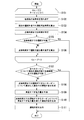
- FIG. 2 is a flowchart showing an operation for each collection period of the turbine analyzer according to the first embodiment.
- the turbine analyzer 1 executes the following process for each collection cycle.
- the data collection unit 101 collects turbine operation data from sensors provided in the turbine (step S1).
- the heat balance calculation unit 102 calculates the heat balance of the turbine using the collected operation data as an input (step S2).
- the turbine analysis device 1 selects the components incorporated in the turbine one by one, and executes the processes from step S4 to step S6 shown below for the selected components (step S3).
- the load specifying unit 103 uses the heat balance calculated by the heat balance calculation unit 102 to calculate an LMP value indicating the load history of the selected component (step S4).
- the remaining life calculating unit 105 calculates the consumed life converted into the operation at the rated temperature based on the LMP value calculated by the load specifying unit 103 (step S5).
- the remaining life calculation unit 105 subtracts the calculated consumed life from the remaining life stored in the remaining life storage unit 104 (step S6). As a result, the remaining life calculation unit 105 updates the remaining life stored in the remaining life storage unit 104.
- the turbine analyzer 1 can maintain the remaining life of each component stored in the remaining life storage unit 104 in the latest state by executing the processing from step S1 to step S6 for each collection period.
- the turbine analyzer 1 reviews the operation plan of each power plant at a timing designated by the user or periodically. That is, when it is predicted that the turbine components will reach the end of their service life by the inspection time by operating the turbine according to the currently used operation plan, all the turbine components will be in the inspection time. The operation plan is changed so that the service life is not reached.
- FIG. 3 is a flowchart showing operation plan generation processing by the turbine analyzer according to the first embodiment.
- the turbine analyzer 1 selects one turbine to be reviewed for the operation plan one by one, and executes the processes from step S102 to step S106 described below for the selected turbine.
- Step S101 the operable time calculation unit 108 reads out the remaining life associated with each component incorporated in the selected turbine from the remaining life storage unit 104 (step S102).
- step S102 the drivable time calculation unit 108 calculates the drivable time for the operation according to the current operation plan for each component (step S103).
- the time specifying unit 107 reads the inspection time associated with the selected turbine from the inspection time storage unit 106, and specifies the time from the present to the inspection time (step S104).
- the driving availability determination unit 109 compares the shortest possible driving time of each component calculated by the driving time calculation unit 108 with the time specified by the time specification unit 107, and until the next inspection time. It is determined whether or not the operation according to the current operation plan is possible (step S105).
- step S105 determines that the selected turbine can be operated according to the current operation plan until the next inspection time (step S105: YES)
- the turbine analyzer 1 returns to step S101, Select the next turbine.
- step S105: NO determines that the selected turbine cannot be operated in accordance with the current operation plan until the next inspection time
- step S106 determines each component. The maximum load capable of operating the selected turbine during the time specified by the time specifying unit 107 is calculated (step S106).
- step S107 the operation plan production
- generation part 112 determines whether all the determination results by the drive availability determination part 109 in step S105 are YES.
- step S107: YES the turbine analyzer 1 generates a new operation plan because there is no need to change the operation plan. The process is terminated without doing so.
- the operation plan generation unit 112 determines the turbine that cannot be operated in accordance with the operation plan until the inspection period. During this period, an operation plan for operating with the load calculated by the load calculation unit 110 is generated (step S108).
- the generated power amount prediction unit 111 acquires market power demand information via the network, and predicts the amount of power that should be generated by the power plant to be managed (step S109).
- the operation plan generation unit 112 generates an operation plan for the turbine to be inspected so as to satisfy the predicted electric energy (step S110).
- the operation plan generation unit 112 shares the generated power amount of the turbine determined to be able to operate according to the operation plan in step S105 so as to satisfy the generated power amount predicted by the generated power amount prediction unit 111. Is calculated. Then, the output unit 113 outputs the operation plan generated by the operation plan generation unit 112 (step S111).
- the turbine analysis device 1 is based on the turbine load history and the design life of the turbine, and the relationship between the turbine load and the operable time when the turbine is operated at the load. Is calculated. Specifically, the operable time calculation unit 108 calculates the operable time of the turbine with the load indicated by the current operation plan. Further, the load calculation unit 110 calculates a load capable of continuing the operation of the turbine for the time specified by the time specifying unit 107. Thereby, the turbine analyzer 1 can appropriately manage the life of the turbine according to the load.
- the turbine analyzer 1 when the turbine cannot continue operation until the inspection time with the load indicated by the current operation plan, the load that can continue the operation of the turbine until the inspection time. calculate. Thereby, the turbine analyzer 1 can change the operation plan so that the components do not reach the service life before the inspection time when there is a possibility that the high-temperature components may reach the service life before the inspection time.
- the turbine analysis device 1 generates an operation plan for a plurality of turbines based on the prediction of the amount of power to be generated by the plurality of turbines. Thereby, even if the operation plan of some turbines is changed so as not to reach the end of its life, the turbine analysis device 1 allows the remaining turbines of the remaining turbines to satisfy the predicted power amount.
- the operation plan can be changed.
- the turbine analyzer 1 determines the operation load of each turbine.
- the owner of a turbine sets the operation load of each turbine.
- the turbine analyzer 1 according to the second embodiment calculates and presents the turbine operable time at the operation load input by the owner.
- FIG. 4 is a schematic block diagram showing the configuration of the turbine analyzer according to the second embodiment.
- the turbine analyzer 1 according to the second embodiment includes an inspection time storage unit 106, a time specifying unit 107, an operation availability determination unit 109, a load calculation unit 110, and a generated power amount prediction unit, among the configurations of the first embodiment. 111 and the operation plan generator 112 are not provided.
- the turbine analyzer 1 according to the second embodiment further includes a load input unit 114 in addition to the configuration of the first embodiment.
- the load input unit 114 receives an input of the turbine operation load from the owner. Based on the remaining life stored in the remaining life storage unit 104, the operable time calculation unit 108 calculates an available operation time when the turbine is operated with the operation load input to the load input unit 114. The output unit 113 outputs the drivable time calculated by the drivable time calculation unit 108.
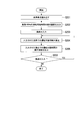
- FIG. 5 is a flowchart showing a process of presenting an operable time by the turbine analyzer according to the second embodiment.
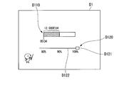
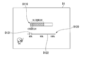
- FIG. 6 is a diagram illustrating a first example of a display screen of a possible operation time output by the turbine analyzer according to the second embodiment.
- the output unit 113 displays a presentation screen D ⁇ b> 1 that presents the drivable time when the load is 100% based on the remaining life read by the drivable time calculator 108 as an initial screen.
- the data is output to the display (step S202).
- the presentation screen D1 is a screen including a drivable time bar D110 and a load bar D120.
- the drivable time bar D110 is an indicator that indicates the drivable time according to its length. The longer the operable time of the turbine, the longer the operable time bar D110. On the other hand, the shorter the operable time of the turbine, the shorter the operable time bar D110.
- the load bar D120 is a slider that receives an input of the turbine operating load.
- the load bar D120 includes a handle D121 and a track D122. An arbitrary load can be selected by dragging and dropping the handle D121 on the track D122.
- a track D122 represents a movable range of the handle D121.
- the load input unit 114 receives an input of a load by receiving an operation of the handle D121 of the load bar D120 from the owner (step S203).
- the operable time calculation unit 108 calculates the operable time when the turbine is operated with the load input to the load input unit 114 based on the remaining life read in step S201 (step S204).
- the LMP value L 1 is calculated by substituting the remaining life t 1 and the rated temperature T s read in step S201 into the above-described equation (3), and the above-described equation (4) is calculated.
- the temperature T p corresponding to the type is calculated LMP value L l to the load input portion 114 loads, calculates the operable time t p.
- FIG. 7 is a diagram illustrating a second example of an operation possible time presentation screen output by the turbine analyzer according to the second embodiment.
- the output unit 113 outputs a presentation screen D1 that presents the drivable time calculated by the drivable time calculation unit 108 to the display (step S205).
- the length of the operable time bar D110 becomes longer than that presented in step S202.
- the drivable time bar D110 displays the increment from the drivable time presented in step S202 in a different manner (for example, color, pattern, etc.). For example, as shown in FIG.
- the load input unit 114 determines whether or not there is a further operation load input from the user (step S206).
- step S206: YES the turbine analyzer 1 returns the process to step S204 and recalculates the operation possible time.
- step S206: NO the turbine analyzer 1 ends the process.
- the turbine analysis device 1 receives an input of a turbine load, and calculates an operable time when the turbine is operated at the load. Thereby, the turbine analyzer 1 can present the operating time when the turbine load is changed to the owner.
- the turbine analyzer 1 determines whether or not the component will reach the end of its life due to creep deformation by using LMP, which is a temperature history variable indicating the temperature history applied to the turbine. I can't.
- LMP which is a temperature history variable indicating the temperature history applied to the turbine.
- other temperature history variables may be used to determine whether a part will reach end of life.
- the turbine analysis apparatus 1 may determine whether or not a component reaches the end of its life due to low cycle fatigue by using a temperature history variable indicating a relationship between the temperature and the number of cycles.
- the turbine analysis apparatus 1 may determine whether or not a part reaches the end of its life based on a plurality of deterioration causes such as creep deformation and low cycle fatigue using a plurality of temperature history variables. Good.
- the turbine analyzer 1 may calculate the consumption life using the load history specified by the turbine inlet temperature (T1T), the load factor, the power generation amount, or other state quantities. .
- the turbine analyzer 1 calculates the operable time of the entire turbine based on the remaining life of each component constituting the turbine, but is not limited thereto.
- the turbine analyzer 1 may calculate the remaining life of the entire turbine directly based on the design life of the entire turbine without calculating the remaining life for each part.
- the load specifying unit 103 performs the calculation based on the heat balance calculated by the heat balance calculating unit 102, but is not limited thereto.
- the load identification unit 103 may perform calculation based on the operation data collected by the data collection unit 101.
- the turbine analysis device 1 may not include the heat balance calculation unit 102.
- FIG. 8 is a schematic block diagram illustrating a configuration of a computer according to at least one embodiment.
- the computer 900 includes a CPU 901, a main storage device 902, an auxiliary storage device 903, and an interface 904.
- the turbine analysis apparatus 1 described above is mounted on a computer 900.
- the operation of each processing unit described above is stored in the auxiliary storage device 903 in the form of a program.
- the CPU 901 reads a program from the auxiliary storage device 903, develops it in the main storage device 902, and executes the above processing according to the program. Further, the CPU 901 secures a storage area corresponding to each of the above-described storage units in the main storage device 902 according to the program.
- the auxiliary storage device 903 is an example of a tangible medium that is not temporary.
- Other examples of the non-temporary tangible medium include a magnetic disk, a magneto-optical disk, a CD-ROM, a DVD-ROM, and a semiconductor memory connected via the interface 904.
- the program may be for realizing a part of the functions described above. Further, the program may be a so-called difference file (difference program) that realizes the above-described function in combination with another program already stored in the auxiliary storage device 903.
- difference file difference program
- the turbine analyzer calculates the relationship between the turbine load and the operable time based on the turbine load history. Thereby, the turbine analyzer can appropriately manage the life of the turbine according to the load.
Landscapes
- Engineering & Computer Science (AREA)
- Chemical & Material Sciences (AREA)
- Combustion & Propulsion (AREA)
- Mechanical Engineering (AREA)
- General Engineering & Computer Science (AREA)
- Physics & Mathematics (AREA)
- General Physics & Mathematics (AREA)
- Materials Engineering (AREA)
- Testing Of Devices, Machine Parts, Or Other Structures Thereof (AREA)
- Control Of Turbines (AREA)
Abstract
Description
本願は、2015年10月28日に日本に出願された特願2015-211899号について優先権を主張し、その内容をここに援用する。
本発明の目的は、タービンの寿命を負荷に応じて適切に管理するタービン分析装置、タービン分析方法およびプログラムを提供することにある。
以下、図面を参照しながら第1の実施形態について詳しく説明する。
図1は、第1の実施形態に係る計画装置の構成を示す概略ブロック図である。
第1の実施形態に係るタービン分析装置1は、複数のタービンの運転計画を生成する。
第1の実施形態に係るタービンの運転計画は、各タービンの運転に係る負荷を示す情報である。
第1の実施形態に係るタービン分析装置1は、データ収集部101、ヒートバランス算出部102、負荷特定部103、余寿命記憶部104、余寿命算出部105、点検時期記憶部106、時間特定部107、運転可能時間算出部108、運転可否判定部109、負荷算出部110、発電電力量予測部111、運転計画生成部112、出力部113を備える。

このように、LMP値は、部品の温度と運転時間とから特定されるパラメータである。
つまり、LMP値は、部品に掛かる温度履歴に関する温度履歴変数の一例である。LMP値により、クリープ変形の程度の状態を表すことができる。また、LMP値は、部品に掛かる負荷の履歴の一例である。
余寿命算出部105は、負荷特定部103が算出したLMP値と、余寿命記憶部104が記憶する部品の余寿命および定格温度とに基づいて、タービンの各部品の余寿命を算出する。
具体的には、余寿命算出部105は、以下の式(2)に、負荷特定部103が算出したLMP値Lcと定格温度Tsとを代入することで、定格温度での運転に換算した消費寿命tsを算出する。そして、余寿命算出部105は、算出された消費寿命を余寿命記憶部104が記憶する余寿命から減算することで、余寿命を算出する。

時間特定部107は、点検時期記憶部が記憶する点検時期に基づいて、現在から点検時期までの時間を特定する。現在から点検時期までの時間は、タービンの運転を継続すべき時間の一例である。



運転計画生成部112は、負荷算出部110が算出した負荷および発電電力量予測部111の予測結果に基づいて、タービンの負荷を示す運転計画を生成する。具体的には、運転計画生成部112は、運転可否判定部109によって、現在の運転計画が示す負荷での運転を継続することができないと判定されたタービンの点検時期までの運転計画を、負荷算出部110が算出した負荷での運転に決定する。そして、運転計画生成部112は、発電電力量予測部111が予測した発電電力量を満たすように、運転可否判定部109によって現在の運転計画が示す負荷での運転を継続することができると判定されたタービンの運転計画を生成する。
出力部113は、運転計画生成部112が生成した運転計画を出力する。運転計画の出力形式の例としては、ディスプレイへの表示、記憶媒体への記録、およびシートへの印刷が挙げられる。
図2は、第1の実施形態に係るタービン分析装置の収集周期ごとの動作を示すフローチャートである。
タービン分析装置1は、収集周期ごとに、以下に示す処理を実行する。
まずデータ収集部101は、タービンに設けられたセンサからタービンの運転データを収集する(ステップS1)。次に、ヒートバランス算出部102は、収集された運転データを入力としてタービンのヒートバランスを算出する(ステップS2)。
まず、負荷特定部103は、ヒートバランス算出部102が算出したヒートバランスを用いて、選択された部品の負荷の履歴を示すLMP値を算出する(ステップS4)。次に、余寿命算出部105は、負荷特定部103が算出したLMP値に基づいて、定格温度での運転に換算した消費寿命を算出する(ステップS5)。次に、余寿命算出部105は、余寿命記憶部104が記憶する余寿命から、算出された消費寿命を減算する(ステップS6)。これにより、余寿命算出部105は、余寿命記憶部104が記憶する余寿命を更新する。
タービン分析装置1は、運転計画の見直し処理を開始すると、運転計画の見直しの対象となるタービンを1つずつ選択し、選択されたタービンについて、以下に示すステップS102からステップS106の処理を実行する(ステップS101)。
まず、運転可能時間算出部108は、選択されたタービンに組み込まれた各部品に関連付けられた余寿命を余寿命記憶部104から読み出す(ステップS102)。次に、運転可能時間算出部108は、各部品について、現在の運転計画に従った運転での運転可能時間を算出する(ステップS103)。次に、時間特定部107は、選択されたタービンに関連付けられた点検時期を、点検時期記憶部106から読み出し、現在から点検時期までの時間を特定する(ステップS104)。次に、運転可否判定部109は、運転可能時間算出部108が算出した各部品の運転可能時間のうち最も短いものと、時間特定部107が特定した時間とを比較し、次回の点検時期まで現在の運転計画に従った運転ができるか否かを判定する(ステップS105)。
そして、出力部113は、運転計画生成部112が生成した運転計画を出力する(ステップS111)。
これにより、タービン分析装置1は、タービンの寿命を負荷に応じて適切に管理することができる。
以下、図面を参照しながら第2の実施形態について詳しく説明する。
第1の実施形態では、タービン分析装置1が各タービンの運転負荷を決定する。これに対し、第2の実施形態では、タービンの所有者が各タービンの運転負荷を設定する。第2の実施形態に係るタービン分析装置1は、所有者によって入力された運転負荷でのタービンの運転可能時間を算出し、提示する。
第2の実施形態に係るタービン分析装置1は、第1の実施形態の構成のうち、点検時期記憶部106、時間特定部107、運転可否判定部109、負荷算出部110、発電電力量予測部111、および運転計画生成部112を備えない。他方、第2の実施形態に係るタービン分析装置1は、第1の実施形態の構成に加え、さらに負荷入力部114を備える。
運転可能時間算出部108は、余寿命記憶部104が記憶する余寿命に基づいて、負荷入力部114に入力された運転負荷でタービンを運転する場合の運転可能時間を算出する。
出力部113は、運転可能時間算出部108が算出した運転可能時間を出力する。
図6は、第2の実施形態に係るタービン分析装置が出力する運転可能時間の提示画面の第1の例を示す図である。
タービン分析装置1は、タービンの所有者から運転可能時間の提示の要求を受け付けると、運転可能時間の提示処理を開始する。運転可能時間算出部108は、運転可能時間の提示対象のタービンの余寿命を余寿命記憶部104から読み出す(ステップS201)。
次に、出力部113は、初期画面として、図6に示すように、運転可能時間算出部108が読み出した余寿命に基づいて、負荷100%のときの運転可能時間を提示する提示画面D1をディスプレイに出力する(ステップS202)。提示画面D1は、運転可能時間バーD110と負荷バーD120とを含む画面である。運転可能時間バーD110は、その長さによって運転可能時間を示すインジケータである。タービンの運転可能時間が長いほど、運転可能時間バーD110の長さが長くなる。他方、タービンの運転可能時間が短いほど、運転可能時間バーD110の長さが短くなる。負荷バーD120は、タービンの運転負荷の入力を受け付けるスライダーである。負荷バーD120は、ハンドルD121とトラックD122とを含む。ハンドルD121は、トラックD122上でドラッグアンドドロップされることにより、任意の負荷を選択することができる。トラックD122は、ハンドルD121の可動範囲を表す。
具体的には、上述した式(3)に、ステップS201で読み出された余寿命tlと定格温度Tsとを代入することでLMP値Llを算出し、上述した式(4)に、算出されたLMP値Llと負荷入力部114に入力された負荷に対応する温度Tpとを代入することで、運転可能時間tpを算出する。
次に、出力部113は、図7に示すように、運転可能時間算出部108が算出した運転可能時間を提示する提示画面D1をディスプレイに出力する(ステップS205)。図7に示すように、負荷入力部114に100%未満の運転負荷が入力されると、運転可能時間バーD110の長さは、ステップS202で提示されたものより長くなる。このとき、運転可能時間バーD110は、ステップS202で提示された運転可能時間からの増加分を、異なる態様(例えば、色、模様など)で表示される。例えば、図6に示すように負荷100%での運転可能時間が12000EOH(等価運転時間:Equivalent Operating Hours)であり、図7に示すように負荷80%での運転可能時間が14000EOHである場合、運転可能時間バーD110のうち増加分である2000EOH相当が、異なる態様で表示される。これにより、所有者は、負荷の変更による運転可能時間の増加量を知ることができる。
例えば、上述した実施形態では、タービン分析装置1がタービンに掛かる温度履歴を示す温度履歴変数であるLMPを用いることで、クリープ変形により部品が寿命に至るか否かを判定するが、これに限られない。例えば、他の実施形態では、他の温度履歴変数を用いて部品が寿命に至るか否かを判定しても良い。例えば、他の実施形態に係るタービン分析装置1は、温度とサイクル数との関係を示す温度履歴変数を用いることで、低サイクル疲労により部品が寿命に至るか否かを判定してもよい。また他の実施形態に係るタービン分析装置1は、複数の温度履歴変数を用いて、クリープ変形および低サイクル疲労など、複数の劣化事由に基づいてパーツが寿命に至るか否かを判定してもよい。
また他の実施形態に係るタービン分析装置1は、タービンの入口温度(T1T)、負荷率、発電量、またはその他の状態量によって特定される負荷の履歴を用いて消費寿命を算出しても良い。
コンピュータ900は、CPU901、主記憶装置902、補助記憶装置903、インタフェース904を備える。
上述のタービン分析装置1は、コンピュータ900に実装される。そして、上述した各処理部の動作は、プログラムの形式で補助記憶装置903に記憶されている。CPU901は、プログラムを補助記憶装置903から読み出して主記憶装置902に展開し、当該プログラムに従って上記処理を実行する。また、CPU901は、プログラムに従って、上述した各記憶部に対応する記憶領域を主記憶装置902に確保する。
さらに、当該プログラムは、前述した機能を補助記憶装置903に既に記憶されている他のプログラムとの組み合わせで実現するもの、いわゆる差分ファイル(差分プログラム)であっても良い。
101 データ収集部
102 ヒートバランス算出部
103 負荷特定部
104 余寿命記憶部
105 余寿命算出部
106 点検時期記憶部
107 時間特定部
108 運転可能時間算出部
109 運転可否判定部
110 負荷算出部
111 発電電力量予測部
112 運転計画生成部
113 出力部
114 負荷入力部
900 コンピュータ
901 CPU
902 主記憶装置
903 補助記憶装置
904 インタフェース
Claims (8)
- タービンの温度を含む前記タービンの状態量を取得する状態量取得部と、
前記状態量に基づいて、前記タービンの負荷の履歴を特定する負荷特定部と、
前記タービンの設計寿命と前記負荷特定部が特定した負荷の履歴とに基づいて、前記タービンの負荷と、前記タービンを当該負荷で運転した場合の運転可能時間との関係を算出する負荷・時間算出部と
を備えるタービン分析装置。 - 前記負荷特定部が、前記状態量に基づいて、前記タービンに掛かる温度履歴を示す温度履歴変数を特定し、
前記負荷・時間算出部が、前記タービンの設計寿命と前記温度履歴変数に基づいて、前記タービンの負荷と、前記タービンを当該負荷で運転した場合の運転可能時間との関係を算出する
請求項1に記載のタービン分析装置。 - 前記タービンの運転を継続すべき時間を特定する時間特定部をさらに備え、
前記負荷・時間算出部が、前記時間特定部が特定した時間の間、前記タービンの運転を継続することができる負荷を算出する
請求項1または請求項2に記載のタービン分析装置。 - 前記タービンが所定の負荷で運転する場合に、所定の検査時期まで運転を継続できるか否かを判定する運転可否判定部をさらに備え、
前記時間特定部が、現在から前記検査時期までの時間を前記タービンの運転を継続すべき時間として特定し、
前記運転可否判定部が運転を継続できないと判定した場合に、前記負荷・時間算出部が、前記時間特定部が特定した時間の間、前記タービンの運転を継続することができる負荷を算出する
請求項3に記載のタービン分析装置。 - 複数の前記タービンが発電すべき電力量を予測する発電電力量予測部と、
前記負荷・時間算出部が算出した前記負荷と、前記発電電力量予測部が予測した電力量とに基づいて、前記複数のタービンの運転計画を生成する運転計画生成部と
をさらに備える請求項3または請求項4に記載のタービン分析装置。 - 前記タービンを運転させる負荷の入力を受け付ける負荷入力部をさらに備え、
前記負荷・時間算出部が、入力された前記負荷による前記タービンの運転可能時間を算出する
請求項1または請求項2に記載のタービン分析装置。 - タービンの温度を含む前記タービンの状態量を取得するステップと、
前記状態量に基づいて、前記タービンの負荷の履歴を特定するステップと、
前記タービンの設計寿命と特定した前記負荷の履歴とに基づいて、前記タービンの負荷と、前記タービンを当該負荷で運転した場合の運転可能時間との関係を算出するステップと
を有するタービン分析方法。 - コンピュータを、
タービンの温度を含む前記タービンの状態量を取得する状態量取得部、
前記状態量に基づいて、前記タービンの負荷の履歴を特定する負荷特定部、
前記タービンの設計寿命と前記負荷特定部が特定した負荷の履歴とに基づいて、前記タービンの負荷と、前記タービンを当該負荷で運転した場合の運転可能時間との関係を算出する負荷・時間算出部
として機能させるためのプログラム。
Priority Applications (5)
| Application Number | Priority Date | Filing Date | Title |
|---|---|---|---|
| KR1020187011880A KR20180059875A (ko) | 2015-10-28 | 2016-10-25 | 터빈 분석 장치, 터빈 분석 방법 및 프로그램 |
| US15/771,302 US10883427B2 (en) | 2015-10-28 | 2016-10-25 | Turbine analysis device, turbine analysis method, and program |
| DE112016004953.6T DE112016004953T5 (de) | 2015-10-28 | 2016-10-25 | Turbinenanalysevorrichtung, turbinenanalyseverfahren und programm |
| MX2018005094A MX2018005094A (es) | 2015-10-28 | 2016-10-25 | Dispositivo de analisis de turbina, metodo de analisis de turbina, y programa. |
| CN201680062564.5A CN108350752B (zh) | 2015-10-28 | 2016-10-25 | 涡轮机分析装置及分析方法、以及计算机可读取记录介质 |
Applications Claiming Priority (2)
| Application Number | Priority Date | Filing Date | Title |
|---|---|---|---|
| JP2015211899A JP6792939B2 (ja) | 2015-10-28 | 2015-10-28 | タービン分析装置、タービン分析方法およびプログラム |
| JP2015-211899 | 2015-10-28 |
Publications (1)
| Publication Number | Publication Date |
|---|---|
| WO2017073554A1 true WO2017073554A1 (ja) | 2017-05-04 |
Family
ID=58631469
Family Applications (1)
| Application Number | Title | Priority Date | Filing Date |
|---|---|---|---|
| PCT/JP2016/081559 Ceased WO2017073554A1 (ja) | 2015-10-28 | 2016-10-25 | タービン分析装置、タービン分析方法およびプログラム |
Country Status (7)
| Country | Link |
|---|---|
| US (1) | US10883427B2 (ja) |
| JP (1) | JP6792939B2 (ja) |
| KR (1) | KR20180059875A (ja) |
| CN (1) | CN108350752B (ja) |
| DE (1) | DE112016004953T5 (ja) |
| MX (1) | MX2018005094A (ja) |
| WO (1) | WO2017073554A1 (ja) |
Cited By (1)
| Publication number | Priority date | Publication date | Assignee | Title |
|---|---|---|---|---|
| JP2024027046A (ja) * | 2022-08-16 | 2024-02-29 | 東芝エネルギーシステムズ株式会社 | 蒸気タービンのクリープ変形評価装置、方法及びプログラム |
Families Citing this family (5)
| Publication number | Priority date | Publication date | Assignee | Title |
|---|---|---|---|---|
| JP5973096B1 (ja) * | 2016-01-14 | 2016-08-23 | 三菱日立パワーシステムズ株式会社 | プラント分析装置、プラント分析方法、およびプログラム |
| JP6892753B2 (ja) | 2016-12-02 | 2021-06-23 | 三菱パワー株式会社 | 機器状態推定装置、機器状態推定方法およびプログラム |
| US11286855B2 (en) * | 2019-03-15 | 2022-03-29 | General Electric Company | Systems and methods for operating a turbine engine |
| JP7288867B2 (ja) * | 2020-01-22 | 2023-06-08 | 三菱重工業株式会社 | 出力指令装置及び出力指令方法 |
| JP7572616B2 (ja) * | 2020-12-08 | 2024-10-24 | 日本製鉄株式会社 | コークス炉クロスタイロッドの監視方法及び監視装置 |
Citations (3)
| Publication number | Priority date | Publication date | Assignee | Title |
|---|---|---|---|---|
| JPS5764141A (en) * | 1980-10-07 | 1982-04-19 | Hitachi Ltd | Method and device for foreseening life of apparatus consisting of metallic structure |
| JP2001317369A (ja) * | 2000-05-11 | 2001-11-16 | Toshiba Corp | ガスタービン運転監視装置 |
| JP2015149885A (ja) * | 2013-12-31 | 2015-08-20 | ゼネラル・エレクトリック・カンパニイ | 発電所発電ユニットの制御を高度化するための方法およびシステム |
Family Cites Families (25)
| Publication number | Priority date | Publication date | Assignee | Title |
|---|---|---|---|---|
| JPS60182305A (ja) * | 1984-02-28 | 1985-09-17 | Toshiba Corp | 蒸気タ−ビンの損傷判定装置 |
| JPS61202136A (ja) * | 1985-03-06 | 1986-09-06 | Hitachi Ltd | 高温ボルトの寿命管理方法 |
| US5447059A (en) * | 1993-12-27 | 1995-09-05 | Solar Turbines Incorporated | Apparatus and method for determining gas turbine engine life |
| US6343251B1 (en) * | 2000-10-20 | 2002-01-29 | General Electric Company | Method and system for monitoring the operation of and predicting part life consumption for turbomachinery |
| JP3692294B2 (ja) | 2000-12-22 | 2005-09-07 | 財団法人電力中央研究所 | ガスタービン高温部品の廃却損最小化方法及びシステム及びガスタービン保守最適化支援プログラムを記録したコンピュータ読取可能な記録媒体 |
| JP3801071B2 (ja) | 2001-02-27 | 2006-07-26 | 株式会社日立製作所 | 発電設備の運転・保全計画支援システム |
| JP3801063B2 (ja) | 2001-02-27 | 2006-07-26 | 株式会社日立製作所 | 発電設備の運転・保全計画支援システム |
| US6853930B2 (en) | 2001-02-27 | 2005-02-08 | Hitachi, Ltd. | System for aiding the preparation of operation and maintenance plans for a power generation installation |
| US7582359B2 (en) * | 2002-09-23 | 2009-09-01 | Siemens Energy, Inc. | Apparatus and method of monitoring operating parameters of a gas turbine |
| US8744864B2 (en) * | 2003-07-29 | 2014-06-03 | General Electric Company | Methods and systems for generating a financial report |
| US7698030B2 (en) * | 2003-09-24 | 2010-04-13 | Siemens Energy, Inc. | Turbine component tracking system |
| JP2005240776A (ja) | 2004-02-27 | 2005-09-08 | Central Res Inst Of Electric Power Ind | 部品運用計画作成方法 |
| JP2009511807A (ja) * | 2005-10-17 | 2009-03-19 | シーメンス アクチエンゲゼルシヤフト | 化石燃料式エネルギ発生設備の構成部品の寿命消費の検出方法と装置 |
| US7368827B2 (en) * | 2006-09-06 | 2008-05-06 | Siemens Power Generation, Inc. | Electrical assembly for monitoring conditions in a combustion turbine operating environment |
| WO2008046931A2 (en) * | 2007-01-10 | 2008-04-24 | Shell Internationale Research Maatschappij B.V. | Method and device to measure, test and/or monitor turbine performance |
| JP4750868B2 (ja) * | 2009-03-19 | 2011-08-17 | 株式会社日立製作所 | 高温下で使用されるボルトの余寿命診断方法 |
| US9056372B2 (en) * | 2010-10-12 | 2015-06-16 | Alstom Technology Ltd | Extending useful life of a cobalt-based gas turbine component |
| PT2710438T (pt) * | 2011-05-20 | 2022-04-20 | Insight Analytics Solutions Holdings Ltd | Determinação de danos e de vida útil restante de mecanismos rotativos, incluindo unidades de tracção, caixas de engrenagens e geradores |
| ITCO20110032A1 (it) * | 2011-07-28 | 2013-01-29 | Nuovo Pignone Spa | Dispositivo e metodo di ottimizzazione e determinazione della vita di una turbina a gas |
| US9317249B2 (en) * | 2012-12-06 | 2016-04-19 | Honeywell International Inc. | Operations support systems and methods for calculating and evaluating turbine temperatures and health |
| CN104850904A (zh) * | 2015-05-12 | 2015-08-19 | 上海能策燃气轮机有限公司 | 一种优化燃气轮机维检修方案的分析方法 |
| JP5862827B2 (ja) | 2015-07-20 | 2016-02-16 | 株式会社三洋物産 | 遊技機 |
| JP6710039B2 (ja) * | 2015-10-28 | 2020-06-17 | 三菱日立パワーシステムズ株式会社 | 計画装置、計画方法およびプログラム |
| GB201621916D0 (en) * | 2016-12-21 | 2017-02-08 | Romax Tech Ltd | Wind farm operation |
| US20180335018A1 (en) * | 2017-05-16 | 2018-11-22 | Frontier Wind, Llc | Turbine Loads Determination and Condition Monitoring |
-
2015
- 2015-10-28 JP JP2015211899A patent/JP6792939B2/ja active Active
-
2016
- 2016-10-25 US US15/771,302 patent/US10883427B2/en active Active
- 2016-10-25 KR KR1020187011880A patent/KR20180059875A/ko not_active Ceased
- 2016-10-25 WO PCT/JP2016/081559 patent/WO2017073554A1/ja not_active Ceased
- 2016-10-25 CN CN201680062564.5A patent/CN108350752B/zh active Active
- 2016-10-25 MX MX2018005094A patent/MX2018005094A/es unknown
- 2016-10-25 DE DE112016004953.6T patent/DE112016004953T5/de active Pending
Patent Citations (3)
| Publication number | Priority date | Publication date | Assignee | Title |
|---|---|---|---|---|
| JPS5764141A (en) * | 1980-10-07 | 1982-04-19 | Hitachi Ltd | Method and device for foreseening life of apparatus consisting of metallic structure |
| JP2001317369A (ja) * | 2000-05-11 | 2001-11-16 | Toshiba Corp | ガスタービン運転監視装置 |
| JP2015149885A (ja) * | 2013-12-31 | 2015-08-20 | ゼネラル・エレクトリック・カンパニイ | 発電所発電ユニットの制御を高度化するための方法およびシステム |
Cited By (2)
| Publication number | Priority date | Publication date | Assignee | Title |
|---|---|---|---|---|
| JP2024027046A (ja) * | 2022-08-16 | 2024-02-29 | 東芝エネルギーシステムズ株式会社 | 蒸気タービンのクリープ変形評価装置、方法及びプログラム |
| JP7778658B2 (ja) | 2022-08-16 | 2025-12-02 | 東芝エネルギーシステムズ株式会社 | 蒸気タービンのクリープ変形評価装置、方法及びプログラム |
Also Published As
| Publication number | Publication date |
|---|---|
| CN108350752A (zh) | 2018-07-31 |
| US10883427B2 (en) | 2021-01-05 |
| US20180328290A1 (en) | 2018-11-15 |
| JP6792939B2 (ja) | 2020-12-02 |
| CN108350752B (zh) | 2020-09-22 |
| KR20180059875A (ko) | 2018-06-05 |
| JP2017082681A (ja) | 2017-05-18 |
| MX2018005094A (es) | 2018-08-15 |
| DE112016004953T5 (de) | 2018-07-19 |
Similar Documents
| Publication | Publication Date | Title |
|---|---|---|
| WO2017073554A1 (ja) | タービン分析装置、タービン分析方法およびプログラム | |
| KR102015744B1 (ko) | 플랜트 분석 장치, 플랜트 분석 방법, 및 프로그램 | |
| JP6247990B2 (ja) | 空調機器管理システム | |
| CN109983484B (zh) | 设备状态估计装置、设备状态估计方法以及记录介质 | |
| JP5874297B2 (ja) | 熱源制御装置、空調システム、熱源制御プログラムおよび熱源制御方法 | |
| CN108368748B (zh) | 计划装置、计划方法以及记录介质 | |
| KR102081573B1 (ko) | 플랜트 분석 장치, 플랜트 분석 방법, 및 프로그램 | |
| KR20110128171A (ko) | 에너지 관리 지원 장치, 에너지 관리 지원 시스템, 에너지 관리 지원 방법 및 프로그램 | |
| JP6635253B2 (ja) | 発電プラント分析装置、発電プラントの分析方法、およびプログラム | |
| CN101784971B (zh) | 用于确定发电厂部件寿命的方法 | |
| JP4664842B2 (ja) | エネルギープラントの最適運用システムと方法、およびプログラム |
Legal Events
| Date | Code | Title | Description |
|---|---|---|---|
| 121 | Ep: the epo has been informed by wipo that ep was designated in this application |
Ref document number: 16859784 Country of ref document: EP Kind code of ref document: A1 |
|
| WWE | Wipo information: entry into national phase |
Ref document number: MX/A/2018/005094 Country of ref document: MX |
|
| ENP | Entry into the national phase |
Ref document number: 20187011880 Country of ref document: KR Kind code of ref document: A |
|
| WWE | Wipo information: entry into national phase |
Ref document number: 15771302 Country of ref document: US |
|
| WWE | Wipo information: entry into national phase |
Ref document number: 112016004953 Country of ref document: DE |
|
| 122 | Ep: pct application non-entry in european phase |
Ref document number: 16859784 Country of ref document: EP Kind code of ref document: A1 |