WO2017073210A1 - 路面状況推定装置 - Google Patents
路面状況推定装置 Download PDFInfo
- Publication number
- WO2017073210A1 WO2017073210A1 PCT/JP2016/078021 JP2016078021W WO2017073210A1 WO 2017073210 A1 WO2017073210 A1 WO 2017073210A1 JP 2016078021 W JP2016078021 W JP 2016078021W WO 2017073210 A1 WO2017073210 A1 WO 2017073210A1
- Authority
- WO
- WIPO (PCT)
- Prior art keywords
- value
- rotation
- threshold value
- tire
- road surface
- Prior art date
- Legal status (The legal status is an assumption and is not a legal conclusion. Google has not performed a legal analysis and makes no representation as to the accuracy of the status listed.)
- Ceased
Links
Images


Classifications
-
- B—PERFORMING OPERATIONS; TRANSPORTING
- B60—VEHICLES IN GENERAL
- B60W—CONJOINT CONTROL OF VEHICLE SUB-UNITS OF DIFFERENT TYPE OR DIFFERENT FUNCTION; CONTROL SYSTEMS SPECIALLY ADAPTED FOR HYBRID VEHICLES; ROAD VEHICLE DRIVE CONTROL SYSTEMS FOR PURPOSES NOT RELATED TO THE CONTROL OF A PARTICULAR SUB-UNIT
- B60W40/00—Estimation or calculation of non-directly measurable driving parameters for road vehicle drive control systems not related to the control of a particular sub unit, e.g. by using mathematical models
- B60W40/02—Estimation or calculation of non-directly measurable driving parameters for road vehicle drive control systems not related to the control of a particular sub unit, e.g. by using mathematical models related to ambient conditions
- B60W40/06—Road conditions
- B60W40/068—Road friction coefficient
-
- B—PERFORMING OPERATIONS; TRANSPORTING
- B60—VEHICLES IN GENERAL
- B60T—VEHICLE BRAKE CONTROL SYSTEMS OR PARTS THEREOF; BRAKE CONTROL SYSTEMS OR PARTS THEREOF, IN GENERAL; ARRANGEMENT OF BRAKING ELEMENTS ON VEHICLES IN GENERAL; PORTABLE DEVICES FOR PREVENTING UNWANTED MOVEMENT OF VEHICLES; VEHICLE MODIFICATIONS TO FACILITATE COOLING OF BRAKES
- B60T8/00—Arrangements for adjusting wheel-braking force to meet varying vehicular or ground-surface conditions, e.g. limiting or varying distribution of braking force
- B60T8/17—Using electrical or electronic regulation means to control braking
- B60T8/171—Detecting parameters used in the regulation; Measuring values used in the regulation
-
- B—PERFORMING OPERATIONS; TRANSPORTING
- B60—VEHICLES IN GENERAL
- B60T—VEHICLE BRAKE CONTROL SYSTEMS OR PARTS THEREOF; BRAKE CONTROL SYSTEMS OR PARTS THEREOF, IN GENERAL; ARRANGEMENT OF BRAKING ELEMENTS ON VEHICLES IN GENERAL; PORTABLE DEVICES FOR PREVENTING UNWANTED MOVEMENT OF VEHICLES; VEHICLE MODIFICATIONS TO FACILITATE COOLING OF BRAKES
- B60T8/00—Arrangements for adjusting wheel-braking force to meet varying vehicular or ground-surface conditions, e.g. limiting or varying distribution of braking force
- B60T8/17—Using electrical or electronic regulation means to control braking
- B60T8/172—Determining control parameters used in the regulation, e.g. by calculations involving measured or detected parameters
- B60T8/1725—Using tyre sensors, e.g. Sidewall Torsion sensors [SWT]
-
- B—PERFORMING OPERATIONS; TRANSPORTING
- B60—VEHICLES IN GENERAL
- B60T—VEHICLE BRAKE CONTROL SYSTEMS OR PARTS THEREOF; BRAKE CONTROL SYSTEMS OR PARTS THEREOF, IN GENERAL; ARRANGEMENT OF BRAKING ELEMENTS ON VEHICLES IN GENERAL; PORTABLE DEVICES FOR PREVENTING UNWANTED MOVEMENT OF VEHICLES; VEHICLE MODIFICATIONS TO FACILITATE COOLING OF BRAKES
- B60T8/00—Arrangements for adjusting wheel-braking force to meet varying vehicular or ground-surface conditions, e.g. limiting or varying distribution of braking force
- B60T8/17—Using electrical or electronic regulation means to control braking
- B60T8/176—Brake regulation specially adapted to prevent excessive wheel slip during vehicle deceleration, e.g. ABS
- B60T8/1763—Brake regulation specially adapted to prevent excessive wheel slip during vehicle deceleration, e.g. ABS responsive to the coefficient of friction between the wheels and the ground surface
-
- B—PERFORMING OPERATIONS; TRANSPORTING
- B60—VEHICLES IN GENERAL
- B60W—CONJOINT CONTROL OF VEHICLE SUB-UNITS OF DIFFERENT TYPE OR DIFFERENT FUNCTION; CONTROL SYSTEMS SPECIALLY ADAPTED FOR HYBRID VEHICLES; ROAD VEHICLE DRIVE CONTROL SYSTEMS FOR PURPOSES NOT RELATED TO THE CONTROL OF A PARTICULAR SUB-UNIT
- B60W30/00—Purposes of road vehicle drive control systems not related to the control of a particular sub-unit, e.g. of systems using conjoint control of vehicle sub-units
- B60W30/18—Propelling the vehicle
- B60W30/18172—Preventing, or responsive to skidding of wheels
-
- G—PHYSICS
- G01—MEASURING; TESTING
- G01M—TESTING STATIC OR DYNAMIC BALANCE OF MACHINES OR STRUCTURES; TESTING OF STRUCTURES OR APPARATUS, NOT OTHERWISE PROVIDED FOR
- G01M17/00—Testing of vehicles
- G01M17/007—Wheeled or endless-tracked vehicles
- G01M17/02—Tyres
- G01M17/025—Tyres using infrasonic, sonic or ultrasonic vibrations
-
- G—PHYSICS
- G01—MEASURING; TESTING
- G01W—METEOROLOGY
- G01W1/00—Meteorology
-
- G—PHYSICS
- G01—MEASURING; TESTING
- G01W—METEOROLOGY
- G01W1/00—Meteorology
- G01W1/02—Instruments for indicating weather conditions by measuring two or more variables, e.g. humidity, pressure, temperature, cloud cover or wind speed
-
- B—PERFORMING OPERATIONS; TRANSPORTING
- B60—VEHICLES IN GENERAL
- B60T—VEHICLE BRAKE CONTROL SYSTEMS OR PARTS THEREOF; BRAKE CONTROL SYSTEMS OR PARTS THEREOF, IN GENERAL; ARRANGEMENT OF BRAKING ELEMENTS ON VEHICLES IN GENERAL; PORTABLE DEVICES FOR PREVENTING UNWANTED MOVEMENT OF VEHICLES; VEHICLE MODIFICATIONS TO FACILITATE COOLING OF BRAKES
- B60T2210/00—Detection or estimation of road or environment conditions; Detection or estimation of road shapes
- B60T2210/10—Detection or estimation of road conditions
- B60T2210/14—Rough roads, bad roads, gravel roads
-
- B—PERFORMING OPERATIONS; TRANSPORTING
- B60—VEHICLES IN GENERAL
- B60T—VEHICLE BRAKE CONTROL SYSTEMS OR PARTS THEREOF; BRAKE CONTROL SYSTEMS OR PARTS THEREOF, IN GENERAL; ARRANGEMENT OF BRAKING ELEMENTS ON VEHICLES IN GENERAL; PORTABLE DEVICES FOR PREVENTING UNWANTED MOVEMENT OF VEHICLES; VEHICLE MODIFICATIONS TO FACILITATE COOLING OF BRAKES
- B60T2240/00—Monitoring, detecting wheel/tyre behaviour; counteracting thereof
- B60T2240/03—Tyre sensors
-
- B—PERFORMING OPERATIONS; TRANSPORTING
- B60—VEHICLES IN GENERAL
- B60W—CONJOINT CONTROL OF VEHICLE SUB-UNITS OF DIFFERENT TYPE OR DIFFERENT FUNCTION; CONTROL SYSTEMS SPECIALLY ADAPTED FOR HYBRID VEHICLES; ROAD VEHICLE DRIVE CONTROL SYSTEMS FOR PURPOSES NOT RELATED TO THE CONTROL OF A PARTICULAR SUB-UNIT
- B60W50/00—Details of control systems for road vehicle drive control not related to the control of a particular sub-unit, e.g. process diagnostic or vehicle driver interfaces
- B60W2050/0001—Details of the control system
- B60W2050/0043—Signal treatments, identification of variables or parameters, parameter estimation or state estimation
- B60W2050/0052—Filtering, filters
- B60W2050/0054—Cut-off filters, retarders, delaying means, dead zones, threshold values or cut-off frequency
- B60W2050/0055—High-pass filters
-
- B—PERFORMING OPERATIONS; TRANSPORTING
- B60—VEHICLES IN GENERAL
- B60W—CONJOINT CONTROL OF VEHICLE SUB-UNITS OF DIFFERENT TYPE OR DIFFERENT FUNCTION; CONTROL SYSTEMS SPECIALLY ADAPTED FOR HYBRID VEHICLES; ROAD VEHICLE DRIVE CONTROL SYSTEMS FOR PURPOSES NOT RELATED TO THE CONTROL OF A PARTICULAR SUB-UNIT
- B60W2420/00—Indexing codes relating to the type of sensors based on the principle of their operation
- B60W2420/90—Single sensor for two or more measurements
-
- B—PERFORMING OPERATIONS; TRANSPORTING
- B60—VEHICLES IN GENERAL
- B60W—CONJOINT CONTROL OF VEHICLE SUB-UNITS OF DIFFERENT TYPE OR DIFFERENT FUNCTION; CONTROL SYSTEMS SPECIALLY ADAPTED FOR HYBRID VEHICLES; ROAD VEHICLE DRIVE CONTROL SYSTEMS FOR PURPOSES NOT RELATED TO THE CONTROL OF A PARTICULAR SUB-UNIT
- B60W2422/00—Indexing codes relating to the special location or mounting of sensors
- B60W2422/70—Indexing codes relating to the special location or mounting of sensors on the wheel or the tyre
Definitions
- the present disclosure relates to a road surface state estimation device that estimates a road surface state based on vibrations received by a tire.
- an acceleration sensor is embedded in the back surface of a tire tread and a road surface condition, for example, an asphalt road, a snow road, a frozen road, or the like is estimated based on a detection signal of the acceleration sensor (for example, a patent) Reference 1).
- a detection signal of the acceleration sensor for example, a patent
- the detection signal of the acceleration sensor is used.
- a vibration component corresponding to the road surface condition is superimposed.
- the road surface condition is estimated by analyzing the frequency component of the vibration in the contact section in which the portion corresponding to the location of the acceleration sensor in the tire tread is in contact with the road surface.
- pulse level The level of the vibration pulse waveform detected by the acceleration sensor (hereinafter referred to as pulse level) varies greatly depending on the traveling speed. For this reason, it is not possible to accurately determine the contact section where the portion corresponding to the location of the acceleration sensor in the tire tread is in contact with the road surface based on the pulse level, and the road surface condition cannot be accurately estimated.
- An object of the present disclosure is to provide a road surface state estimation device capable of accurately determining a contact section in which a portion corresponding to an arrangement position of a vibration detection unit that detects vibration of a tire is in contact with a road surface. .
- the road surface state estimation device has a tire-side device and a vehicle-side device.
- the tire-side device is attached to the rear surface of a tread of a tire provided in the vehicle, and outputs a vibration detection unit that outputs a detection signal corresponding to the magnitude of tire vibration, and a vibration detection unit of the tread during one rotation of the tire.
- a signal processing unit having a section specifying unit for identifying a grounding section in which a portion corresponding to the arrangement location of the ground is grounded, a level calculating unit for calculating a level of a high frequency component of a detection signal in the grounding section, and a level of the high frequency component
- a transmitter that transmits the calculation result as road surface state data representing the road surface state.
- the vehicle-side device includes a receiver that receives the road surface condition data transmitted from the transmitter, and a road surface state estimation unit that estimates the road surface state of the tire traveling road surface based on the road surface state data. It is said that.
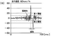
- the section specifying unit sets a first threshold value to be compared with the pulse level of the pulse waveform indicated by the detection signal and a second threshold value smaller than the first threshold value according to the traveling speed of the vehicle.
- the threshold value setting unit and the next maximum value when the pulse waveform indicated by the detection signal is larger than the first threshold value are set as the start of grounding, and the next minimum value when the pulse waveform is smaller than the second threshold value is set as the end of the grounding.
- a section extracting unit that extracts a section from the start of contact to the end of contact as a contact section.
- the detection signal of the vibration detection unit in the ground contact section is extracted for detecting the road surface condition.
- grounding area in that case are made variable according to the running speed of a vehicle.
- the road surface state estimation device is used for estimating a road surface state during traveling based on vibrations on a ground contact surface of a tire provided in each wheel of the vehicle.
- the road surface state estimating device 100 is configured to include a tire side device 1 provided on the tire side and a vehicle side device 2 provided on the vehicle body side. And the road surface condition estimation apparatus 100 transmits the data showing the road surface condition during driving
- the tire side device 1 and the vehicle side device 2 are configured as follows.
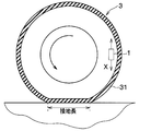
- the tire-side device 1 is configured to include a vibration power generation element 11, a power supply circuit 12, a processing circuit unit 13, and a transmitter 14, and as illustrated in FIG. 2, Provided on the back side of the tread 31.
- the vibration power generation element 11 generates a detection signal corresponding to the vibration in the tire tangential direction shown as the direction of the arrow X in FIG. 2 in the direction in contact with the circular orbit drawn by the tire side device 1 when the tire 3 rotates. It constitutes a vibration detection unit that outputs.
- the vibration energy is converted into electric energy, and the power source of the tire side device 1 is generated based on the vibration energy. ing.
- the vibration power generation element 11 is disposed so as to generate power with respect to vibration in the tire tangential direction.
- an electrostatic induction type power generation element for example, electret
- a piezoelectric element for example, a friction type, a magnetostriction type, or an electromagnetic induction type element
- an acceleration sensor can be used as the detection signal corresponding to the vibration in the tire tangential direction not taking into account the power generation application.
- an electrostatic induction type power generation element when used as the vibration power generation element 11, if the upper electrode charged positively by electrostatic induction is vibrated in the horizontal direction with respect to the lower electrode having a negative charge, Electricity is generated by changing the electric charge due to electrical induction and generating electromotive force. Based on such power generation by the vibration power generation element 11, the power source of the tire side device 1 is generated, and a detection signal corresponding to the magnitude of vibration in the tire tangential direction is generated.
- the processing circuit unit uses the output voltage of the vibration power generation element 11 as a detection signal representing the magnitude of vibration in the tire tangential direction. 13 to tell.
- the output voltage of the vibration power generation element 11 is an alternating voltage because the upper electrode reciprocates due to vibration.
- the power supply circuit 12 is a circuit for storing power based on the output voltage of the vibration power generation element 11 to generate a power source and supplying power to the processing circuit unit 13 and the transmitter 14.
- the power supply circuit 12 is a rectifier circuit 15 and a power storage circuit 16. It is set as the structure provided with.
- the rectifier circuit 15 is a known circuit that converts an alternating voltage output from the vibration power generation element 11 into a direct current.
- the AC voltage output from the vibration power generation element 11 is DC converted by the rectifier circuit 15 and output to the power storage circuit 16.
- the rectifier circuit 15 may be a full-wave rectifier circuit or a half-wave rectifier circuit.
- the accumulator circuit 16 is a circuit for accumulating the DC voltage applied from the rectifier circuit 15, and is constituted by a capacitor or the like.
- the output voltage of the vibration power generation element 11 is stored in the power storage circuit 16 via the rectifier circuit 15, and the power stored in the power storage circuit 16 is used as a power supply to the processing circuit unit 13 and the transmitter 14 included in the tire side device 1. Supplying.
- the power supply circuit 12 includes the power storage circuit 16, when the vibration power generation element 11 is generating excessive power, the surplus is stored, and when the power generation amount is insufficient, the shortage is stored. It comes to be able to compensate.
- the processing circuit unit 13 corresponds to a signal processing unit, and uses the output voltage of the vibration power generation element 11 as a detection signal representing vibration data in the tire tangential direction, and represents the road surface condition by processing this detection signal. It is responsible for obtaining data and communicating it to the transmitter 14. Specifically, the processing circuit unit 13 specifies the grounding section based on the time change of the output voltage of the vibration power generation element 11.
- the contact section here means a section in which a portion of the tread 31 of the tire 3 corresponding to the position where the vibration power generation element 11 is disposed is grounded on the road surface.
- the grounding section is specified by comparing the pulse level of the output voltage of the vibration power generation element 11 with a threshold value, but the pulse level of the output voltage changes according to the traveling speed. For this reason, by setting a threshold value corresponding to the traveling speed by the section identifying unit 17 described later, the ground contact section can be accurately identified according to the traveling speed.
- the processing circuit unit 13 extracts the high frequency component and the road surface based on the extracted high frequency component. Data representing the situation is generated and transmitted to the transmitter 14.
- the processing circuit unit 13 is configured by a known microcomputer having various circuits, a CPU, a ROM, a RAM, an I / O, and the like, and performs the above processing based on the output voltage of the vibration power generation element 11. ing.
- the processing circuit unit 13 includes a section specifying unit 17 and a level calculating unit 18 as parts for performing these processes.
- the section specifying unit 17 plays a role of specifying the grounding section and notifying the level calculating unit 18 that the grounding section is being performed.
- the section specifying unit 17 includes a section extracting unit 17a, a peak value detecting unit 17b, a threshold calculating unit 17c, and a threshold setting unit 17d.
- the section extracting unit 17a detects the peak value of the detection signal represented by the output voltage of the vibration power generation element 11, thereby extracting that it is in the grounding section and telling the level calculating unit 18 that it is in the grounding section. Tell.
- the section extraction unit 17a also causes the transmitter 14 to generate a transmission trigger that causes the vehicle-side device 2 to transmit the calculation result of the level calculation unit 18 as road surface state data representing the road surface state.
- the function of the section extraction unit 17a will be specifically described.
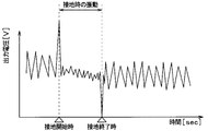
- the section extraction unit 17a detects the timing of the second peak value at which the output voltage of the vibration power generation element 11 takes a minimum value as the end of grounding. Specifically, when the output voltage of the vibration power generation element 11 becomes smaller than the second threshold specified by the section specifying unit 17 as will be described later, the next minimum value is detected and the end of grounding is detected. Yes. In this way, by detecting the minimum value of the output voltage on the condition that the output voltage of the vibration power generation element 11 becomes smaller than the second threshold value, it is possible to accurately detect the start of grounding.
- the reason why the vibration power generation element 11 takes the peak value at the above timing is as follows. That is, when the portion of the tread 31 corresponding to the placement location of the vibration power generation element 11 comes into contact with the rotation of the tire 3, the portion of the tire 3 that has been substantially cylindrical in the vicinity of the vibration power generation element 11 is It is pressed and deformed into a flat shape. By receiving the impact at this time, the output voltage of the vibration power generation element 11 takes the first peak value. Further, when the portion of the tread 31 corresponding to the place where the vibration power generation element 11 is disposed is separated from the grounding surface as the tire 3 rotates, the tire 3 is released from pressing in the vicinity of the vibration power generation element 11 and is planar. To return to a substantially cylindrical shape.
- the output voltage of the vibration power generation element 11 takes the second peak value. In this way, the output voltage of the vibration power generation element 11 takes the first and second peak values at the start and end of grounding, respectively. Moreover, since the direction of the impact when the tire 3 is pressed and the direction of the impact when released from the press are opposite directions, the sign of the output voltage is also opposite.
- the section extraction unit 17a transmits the timings of the first and second peak values to the level calculation unit 18, and outputs the output voltage of the vibration power generation element 11 during the period from the timing of the first peak value to the timing of the second peak value.
- An instruction to rectify and integrate the high-frequency components contained is issued. In this way, the section extraction unit 17a extracts the ground contact section and notifies the level calculation unit 18 that it is in the ground contact section.
- the section extraction unit 17a sends a transmission trigger to the transmitter 14 at this timing.
- the transmitter 14 transmits the calculation result transmitted from the level calculation unit 18 as road surface condition data. In this way, data transmission by the transmitter 14 is not always performed, but only when the vibration power generation element 11 is grounded, so that power consumption can be reduced.
- the peak value detector 17b detects the peak value of the output voltage of the vibration power generation element 11, and stores the peak value as the peak value of the output voltage of the vibration power generation element 11 at the time of the previous tire rotation, that is, before one rotation.
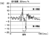
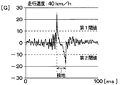
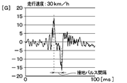
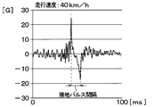
- the threshold value calculation unit 17c calculates the first threshold value and the second threshold value based on the peak value of the output voltage of the vibration power generation element 11 during the previous tire rotation stored in the peak value detection unit 17b. That is, the pulse level of the output voltage of the vibration power generation element 11 varies according to the traveling speed. For example, as shown in FIGS. 4A to 4C, the pulse level of the output voltage of the vibration power generation element 11 decreases as the vehicle traveling speed decreases, and the output of the vibration power generation element 11 increases as the vehicle traveling speed increases. The voltage pulse level increases. In FIGS. 4A to 4C, the vertical axis represents the acceleration applied to the vibration power generation element 11, but the output voltage of the vibration power generation element 11 has the same waveform.
- the first threshold value and the second threshold value are set to constant values, even if the output voltage of the vibration power generation element 11 takes a maximum value or a minimum value when the traveling speed of the vehicle is low, it is between the first threshold value and the second threshold value. May not exceed range. Further, when the first threshold value and the second threshold value are set to constant values, even when the output voltage of the vibration power generation element 11 does not take the maximum value or the minimum value when the traveling speed of the vehicle is high, it is between the first threshold value and the second threshold value. May exceed the range. In this case, as shown in FIG. 4C, the maximum value and the minimum value are erroneously detected.
- the first threshold value and the second threshold value are changed according to the peak value of the output voltage of the vibration power generation element 11 at the time of the previous tire rotation, thereby obtaining a value that follows the traveling speed of the vehicle. Like that.
- the first threshold value is calculated based on the first peak value at the previous tire rotation
- the second threshold value is calculated based on the second peak value at the previous tire rotation.
- the initial value is set for the first threshold, and a new first threshold is set by correcting the initial value.
- the initial value is set to a threshold value at the minimum traveling speed to be sensed.
- the first threshold value increases as the first peak value increases and decreases as the first peak value decreases in accordance with the first peak value during the previous tire rotation.
- the first threshold value is increased or decreased by an amount corresponding to the difference between the first peak values during the previous and current tire rotations, or by an amount obtained by multiplying the difference by a predetermined coefficient.
- the initial value is also set for the second threshold, and a new second threshold is set by correcting this initial value.
- the initial value is set to a threshold value at the minimum traveling speed to be sensed.
- the second threshold value is smaller than the first threshold value.
- the second threshold value is decreased as the second peak value is decreased in accordance with the second peak value during the previous tire rotation, and the second peak value is increased. Increased.
- the second threshold value is decreased or increased by the difference between the second peak values during the previous and current tire rotations, or by the amount obtained by multiplying the difference by a predetermined coefficient.
- the first threshold value and the second threshold value are variably set based on the first peak value and the second peak value at the previous tire rotation. Therefore, even if the pulse level of the output voltage of the vibration power generation element 11 changes according to the traveling speed of the vehicle, the first threshold value and the second threshold value corresponding to the pulse level can be set. Therefore, accurate determination can be performed by determining the contact section using the first threshold value and the second threshold value.
- the maximum value and minimum value of the output signal of the vibration electric power generation element 11 for predetermined tire rotation speed are the range between a 1st threshold value and a 2nd threshold value.
- the first threshold value and the second threshold value are returned to the initial values again.
- the level calculation unit 18 calculates the level of the high-frequency component caused by the vibration of the tire 3 included in the output voltage of the vibration power generation element 11 during the period. . Then, the level calculation unit 18 transmits the calculation result to the transmitter 14 as road surface state data representing the road surface state.
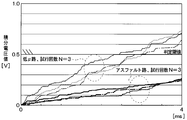
- the level of the high-frequency component is calculated as an index representing the road surface condition, and the reason will be described with reference to FIGS.
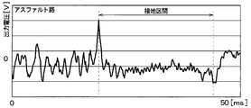
- FIG. 5A shows a change in the output voltage of the vibration power generation element 11 when traveling on a high ⁇ road surface having a relatively large road surface ⁇ such as an asphalt road.
- FIG. 5B shows a change in the output voltage of the vibration power generation element 11 when traveling on a low ⁇ road surface having a relatively small road surface ⁇ such as a frozen road.
- the first and second peak values appear at the beginning and end of the grounding section, that is, at the start and end of grounding of the vibration power generation element 11, regardless of the road surface ⁇ .
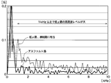
- the road surface ⁇ due to the influence of the road surface ⁇ , when the vehicle is traveling on a low ⁇ road surface, fine high-frequency vibration due to the slip of the tire 3 is superimposed on the output voltage. For this reason, when the frequency analysis of the output voltage in the grounding section is performed for each of the case where the vehicle is traveling on the high ⁇ road surface and the case where the vehicle is traveling on the low ⁇ road surface, the result shown in FIG. 6 is obtained.
- the level of the high frequency component of the output voltage of the vibration power generation element 11 is an index representing the road surface condition.
- the level calculation unit 18 calculates the level of the high frequency component of the output voltage of the vibration power generation element 11 during the grounding section by the level calculation unit 18, this can be used as road surface condition data.
- the level of the high frequency component can be calculated by extracting the high frequency component from the output voltage of the vibration power generation element and integrating the extracted high frequency component during the grounding section.
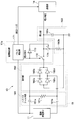
- FIG. 7 is a diagram showing a specific circuit configuration of the processing circuit unit 13 applied when the level of the high frequency component is calculated by integrating the high frequency component extracted during the grounding section.
- the section extraction unit 17 a receives the detection signal (output voltage) of the vibration power generation element 11, outputs an integration instruction signal to the level calculation unit 18 based on the analysis result of the detection signal, and transmits to the transmitter 14. To output a transmission trigger.
- the section extraction unit 17a has a ground pulse detection unit 171, and the ground pulse detection unit 171 detects the peak of the detection signal when the vibration power generation element 11 is grounded and when the grounding is terminated. Yes. Then, the ground pulse detection unit 171 outputs an integration instruction signal when the detection signal of the vibration power generation element 11 reaches the first peak value, and cancels the integration instruction signal when the detection signal reaches the second peak value.
- the switch 172 when a high level is output as an integration instruction signal from the ground pulse detector 171, the switch 172 is turned on, and when it is inverted by the inverter 173 and a low level is transmitted, the switch 174 is turned off and the high frequency component is turned on. Integration of starts.
- the switch 172 is turned off, and when it is inverted by the inverter 173 and a high level is transmitted, the switch 174 is turned on and the high frequency component is generated. Integration is terminated.
- the level calculation unit 18 includes a high-pass filter unit 181, a rectification unit 182 and an integration unit 183.
- the high-pass filter unit 181 constitutes a high-frequency component extraction unit that extracts a high-frequency component of the detection signal of the vibration power generation element 11.
- the high-pass filter unit 181 is configured by a CR filter circuit having capacitors 181a and 181b and a resistor 181c. Only the high-frequency component of the detection signal of the vibration power generation element 11 is adjusted by adjusting the capacitance values of the capacitors 181a and 181b and the resistance value of the resistor 181c. Pass through.
- the rectifying unit 182 is configured by a full-wave rectifier circuit having diodes 182a to 182d arranged in a bridge shape, and full-wave rectifies the high-frequency component of the detection signal extracted by the high-pass filter unit 181. Thereby, only the positive voltage after full-wave rectification can be applied to the integrating unit 183.
- the integrating unit 183 is a part that integrates the high-frequency component of the detection signal of the vibration power generation element 11, and in this embodiment, the integrating unit 183 has a configuration including a capacitor 183a and a resistor 183b.
- the capacitor 183a is charged based on the high-frequency component after full-wave rectification.
- the charging voltage of the capacitor 183a corresponds to a value obtained by integrating the high frequency component, and the integrated voltage value of the capacitor 183a is input to the transmitter 14 as data representing the road surface condition. That is, as shown in FIG. 6, since the level of the high frequency component of the detection signal of the vibration power generation element 11 is different between the case where the traveling road surface is a low ⁇ road surface and the case where the road surface is a high ⁇ road surface, Accordingly, the integrated voltage value of the capacitor 183a changes.
- the number of trials N 3.
- the traveling road surface is a low ⁇ road surface
- the level of the high frequency component of the detection signal of the vibration power generation element 11 is higher than that of the high ⁇ road surface, so that the integrated voltage value of the capacitor 183a is growing.
- the integrated voltage value of the capacitor 183a becomes data representing the road surface condition.
- the resistor 183b is connected to the capacitor 183a to discharge the capacitor 183a when the ground pulse detector 171 releases the integration instruction signal and the switch 174 is turned on. As a result, the voltage of the capacitor 183a can be reset to 0 when the high-frequency component is integrated next time.
- the processing circuit unit 13 can be configured by such a circuit, and the high-frequency component of the output voltage of the vibration power generation element 11 is integrated by the integration unit 183, thereby calculating the level of the high-frequency component in the ground section. Can do.
- the transmitter 14 transmits the road surface condition data transmitted from the processing circuit unit 13 to the vehicle-side device 2.
- Communication between the transmitter 14 and the receiver 21 included in the vehicle-side device 2 can be performed by a known short-range wireless communication technology such as Bluetooth (registered trademark).
- the timing for transmitting the road surface condition data is arbitrary, but as described above, in the present embodiment, the road surface condition is transmitted from the transmitter 14 by sending a transmission trigger from the section extraction unit 17a when the grounding of the vibration power generation element 11 is completed. Data is sent. In this way, data transmission by the transmitter 14 is not always performed, but only when the vibration power generation element 11 is grounded, so that power consumption can be reduced.
- the road surface condition data can be sent together with the unique recognition information (hereinafter referred to as ID information) of the wheels provided in advance for each tire 3 provided in the vehicle.
- ID information unique recognition information
- the position of each wheel can be specified by a well-known wheel position detection device that detects which position of the vehicle the wheel is attached to. Therefore, by transmitting road surface condition data together with ID information to the vehicle side device 2, which wheel is detected. It is possible to determine whether it is the data.
- the road surface ⁇ of the road surface is assumed to be uniform, but there are ⁇ split roads with different road surface ⁇ between the left and right wheels of the vehicle, and on such ⁇ split roads road surface condition data is transmitted for each wheel.
- the average value of the integrated voltage value indicated by the road surface data sent from each wheel is used to estimate the road surface condition. You may make it use for estimation of.
- the vehicle-side device 2 is configured to include a receiver 21 and a road surface condition estimation unit 22, and receives road surface condition data transmitted from the tire-side device 1, and performs various processes based on this data. By doing so, the road surface condition while traveling is detected.
- the receiver 21 is a device for receiving road surface condition data transmitted by the tire side device 1.
- the road surface condition data received by the receiver 21 is sequentially output to the road surface state estimation unit 22 every time it is received.
- the road surface condition estimation unit 22 is configured by a known microcomputer including a CPU, ROM, RAM, I / O, and the like, and performs processing for detecting road surface conditions in accordance with a program stored in the ROM or the like. Specifically, the road surface state estimation unit 22 estimates the road surface ⁇ based on the magnitude of the integrated voltage value indicated by the road surface state data. For example, if the integrated voltage value is larger than the determination threshold, the road surface is low ⁇ . If the road surface is small, the traveling road surface is determined to be a high ⁇ road surface. As shown in FIG.
- the determination threshold is set to an intermediate value between an integrated voltage value assumed when the traveling road surface is a low ⁇ road surface and an integrated voltage value assumed when the traveling road surface is a high ⁇ road surface. For this reason, it is possible to estimate the road surface condition of the traveling road surface by comparing with the determination threshold value.
- the estimation result is placed in, for example, CAN (abbreviation of Controller Area Network) communication that is an in-vehicle network.
- the estimation result of the road surface condition is input to, for example, an electronic control device (so-called brake ECU) for brake control and used for setting an index for performing antilock brake control, for example, a control start threshold value in antilock brake control. .
- brake ECU electronice control device
- the road surface condition estimation apparatus 100 extracts the detection signal of the vibration power generation element 11 in the ground contact section for detection of the road surface condition.
- the threshold value used for the determination of being in the ground contact section at that time is made variable according to the traveling speed of the vehicle. Therefore, even if the pulse level of the output voltage of the vibration power generation element 11 changes according to the traveling speed of the vehicle, a threshold value corresponding to the pulse level can be set.
- determining the ground contact section using such a threshold value it is possible to perform accurate determination. Therefore, it is possible to detect the road surface condition with high accuracy based on the contact section determined with high accuracy.
- the tire side device 1 calculates the level of the high frequency component of the detection signal of the vibration power generation element 11 during the ground contact section, and transmits it as road surface condition data. And the road surface condition data is received by the vehicle side apparatus 2, and the road surface condition of the traveling road surface is estimated. As a result, it is possible to estimate the road surface condition without performing frequency analysis, thereby reducing power consumption and reducing frequency analysis components. Therefore, cost reduction can be achieved.
- the processing circuit unit 13 extracts the high frequency component by passing the detection signal of the vibration power generation element 11 through the high pass filter unit 181, and then charges the capacitor 183 a after rectification until the grounding of the vibration power generation element 11 is completed. An integrated voltage value is obtained.
- the portion other than the ground pulse detection unit 171 in the processing circuit unit 13 can be composed mainly of an analog circuit, so that signal processing can be performed with a low-cost and space-saving circuit.
- the tire side apparatus 1 should just transmit the integrated voltage value by the capacitor
- first threshold value and the second threshold value are set independently, in which the first threshold value is changed based on the first peak value and the second threshold value is changed based on the second peak value, will be described. did. However, these can also be set in association so that the first threshold value and the second threshold value are set more accurately.
- the first threshold value is changed to a large value
- the second threshold value is changed to a small value.
- the maximum value and the minimum value change in terms of noise. It is possible to prevent the first threshold value and the second threshold value from being erroneously changed.
- the present embodiment is a modification of the threshold setting method used for detecting the grounding section with respect to the first embodiment, and the rest is the same as the first embodiment. Only explained.
- the first threshold value and the second threshold value are set based on the first peak value and the second peak value at the previous tire rotation.
- the first threshold value and the second threshold value are set based on the time interval between the first peak value and the second peak value at the time of the previous tire rotation (hereinafter referred to as the ground pulse interval). To do.
- the ground contact pulse interval changes according to the traveling speed of the vehicle, and is longer as the traveling speed is lower and shorter as the traveling speed is higher. For this reason, the ground pulse interval changes according to the traveling speed of the vehicle. Therefore, by setting a threshold corresponding to the traveling speed based on the grounding pulse interval, the grounding section can be accurately extracted according to the traveling speed.
- the section specifying unit 17 is configured to include a pulse interval detecting unit 17e, a threshold calculating unit 17f, and a threshold setting unit 17g as shown in FIG.
- the pulse interval detection unit 17e detects a first peak value that is a maximum value and a second peak value that is a minimum value of the output voltage of the vibration power generation element 11, and sets these time intervals as the ground pulse interval during the previous tire rotation.
- the threshold value calculation unit 17f calculates the first threshold value and the second threshold value based on the ground contact pulse interval at the previous tire rotation stored in the pulse interval detection unit 17e.
- the ground pulse interval varies depending on the traveling speed. For example, as shown in FIGS. 10 (a) to 10 (c), the lower the traveling speed of the vehicle, the shorter the ground pulse interval, and the higher the traveling speed of the vehicle, the longer the ground pulse interval.
- the first threshold value and the second threshold value are changed in accordance with the ground pulse interval at the time of the previous tire rotation so as to follow the traveling speed of the vehicle.
- the first threshold value and the second threshold value are variably set as follows.
- the initial value is set for the first threshold, and a new first threshold is set by correcting the initial value.
- the initial value is set to a threshold value at the minimum traveling speed to be sensed.
- the first threshold value decreases as the ground pulse interval during the previous tire rotation increases, and increases as the ground pulse interval decreases.
- the first threshold value is increased or decreased by an amount corresponding to the difference between the previous and current ground pulse intervals multiplied by a predetermined coefficient.
- the initial value is also set for the second threshold, and a new second threshold is set by correcting this initial value.
- the initial value is set to a threshold value at the minimum traveling speed to be sensed.
- the second threshold value is smaller than the first threshold value.
- the second threshold value is increased as the ground pulse interval during the previous tire rotation is increased, and is decreased as the ground pulse interval is decreased.
- the second threshold value is decreased or increased by an amount obtained by multiplying the difference between the ground pulse intervals during the previous and current tire rotations by a predetermined coefficient.
- the first threshold value and the second threshold value are variably set based on the ground contact pulse interval at the previous tire rotation. Therefore, even if the pulse level of the output voltage of the vibration power generation element 11 changes according to the traveling speed of the vehicle, the first threshold value and the second threshold value corresponding to the pulse level can be set. Therefore, accurate determination can be performed by determining the contact section using the first threshold value and the second threshold value.
- the maximum value and minimum value of the output signal of the vibration electric power generation element 11 for predetermined tire rotation speed are the range between a 1st threshold value and a 2nd threshold value.
- the first threshold value and the second threshold value are returned to the initial values again.
- the first threshold value and the second threshold value can be variably set based on the ground pulse interval at the previous tire rotation. Even if it does in this way, the effect similar to 1st Embodiment can be acquired.
- the local maximum value during the current tire rotation is greater than the first peak value, the local minimum value during the current tire rotation is smaller than the second peak value, and the ground pulse interval during the current tire rotation is one. It is determined whether it is shorter than the ground pulse interval before rotation. Then, only when these conditions are satisfied, the first threshold value is changed to a larger value than before one rotation, and the second threshold value is changed to a smaller value than before one rotation. Similarly, the local maximum value during the current tire rotation is smaller than the first peak value, the local minimum value during the current tire rotation is larger than the second peak value, and the ground pulse interval during the current tire rotation is further increased. It is determined whether it is longer than the ground pulse interval before one rotation. Then, only when these conditions are satisfied, the first threshold value is changed to a smaller value than before one rotation, and the second threshold value is changed to a larger value than before one rotation.
- the first threshold value and the second threshold value can be set more accurately, and further, the ground contact section can be recognized accurately and the road surface condition can be detected with higher accuracy.
- the traveling speed of the vehicle can be estimated based on the grounding pulse interval, and further, the time required until the next grounding section can be estimated. Therefore, the section extraction unit 17a is provided with a mask function so that the first peak value and the second peak value are not set before the time when the next section is assumed to be a grounding section.
- the section extraction unit 17a calculates the time that is expected to be taken from the end of the current grounding to the next grounding section based on the previous grounding pulse interval. And even if the output voltage of the vibration power generation element 11 becomes larger than the first threshold value or becomes smaller than the second threshold value during the predetermined period before reaching the time, the first peak value or the second value is extracted by the section extraction unit 17a. Prevent peak values from being set. As described above, even when the output voltage of the vibration power generation element 11 is larger than the first threshold value or smaller than the second threshold value when it is assumed that it is not the ground section, the first peak value and the second peak value are set. I'm trying not to be. As a result, it is possible to prevent erroneous determination as a ground contact section or erroneous change of the first threshold value or the second threshold value.
- the first threshold value and the second threshold value can be set more accurately, and further, the ground contact section can be recognized accurately and the road surface condition can be detected with higher accuracy.
- the first threshold value and the second threshold value are set based on the first peak value and the second peak value at the previous tire rotation.
- the first threshold value and the second threshold value are set based on the centrifugal force (hereinafter referred to as tire centrifugal force) that works due to tire rotation.
- the tire centrifugal force changes according to the traveling speed of the vehicle, and decreases as the traveling speed decreases and increases as the traveling speed increases. For this reason, the tire centrifugal force changes according to the traveling speed of the vehicle. Therefore, by setting a threshold value corresponding to the traveling speed based on the tire centrifugal force, the ground contact section can be accurately extracted according to the traveling speed.
- the section specifying unit 17 includes a centrifugal force detecting unit 17h, a threshold calculating unit 17i, and a threshold setting unit 17j in addition to the section extracting unit 17a. .
- the centrifugal force detection unit 17h detects the centrifugal force acting on the vibration detection power generation unit 11.
- the vibration detection power generation unit 11 is provided with an acceleration sensor that can detect centrifugal force, and the centrifugal force detection unit 17h operates the vibration detection power generation unit 11 by using a detection signal of the acceleration sensor. Force can be detected.
- the threshold value calculation unit 17 f calculates the first threshold value and the second threshold value based on the centrifugal force detected by the centrifugal force detection unit 17.
- the centrifugal force varies according to the traveling speed. The lower the traveling speed of the vehicle, the smaller the centrifugal force. The higher the traveling speed of the vehicle, the larger the centrifugal force.
- the first threshold value and the second threshold value are changed according to the centrifugal force at the time of the previous tire rotation so as to follow the traveling speed of the vehicle.
- the first threshold value and the second threshold value are variably set as follows.
- the initial value is set for the first threshold, and a new first threshold is set by correcting the initial value.
- the initial value is set to a threshold value at the minimum traveling speed to be sensed.
- the first threshold value decreases as the centrifugal force during the previous tire rotation decreases, and increases as the centrifugal force increases.
- the first threshold value is decreased or increased by an amount obtained by multiplying the difference between the previous and current centrifugal forces by a predetermined coefficient.
- the initial value is also set for the second threshold, and a new second threshold is set by correcting this initial value.
- the initial value is set to a threshold value at the minimum traveling speed to be sensed.
- the second threshold value is smaller than the first threshold value.
- the second threshold value is increased as the centrifugal force during the previous tire rotation is decreased, and is decreased as the centrifugal force is increased.
- the second threshold value is decreased or increased by an amount obtained by multiplying the difference in centrifugal force between the previous and current tire rotations by a predetermined coefficient.
- the first threshold value and the second threshold value are variably set based on the centrifugal force during the previous tire rotation. Therefore, even if the pulse level of the output voltage of the vibration power generation element 11 changes according to the traveling speed of the vehicle, the first threshold value and the second threshold value corresponding to the pulse level can be set. Therefore, accurate determination can be performed by determining the contact section using the first threshold value and the second threshold value.
- the first threshold value and the second threshold value can be variably set based on the centrifugal force during the previous tire rotation. Even if it does in this way, the effect similar to 1st Embodiment can be acquired.
- the peak value detection unit 17b may store the peak value of the output voltage of the vibration power generation element 11 at the previous tire rotation, but the output voltage of the vibration power generation element 11 at the previous number of tire rotations including the previous time.
- the peak value can also be stored.
- the average value of the peak value of the output voltage of the vibration power generation element 11 in the number of rotations of the tire is obtained, and the average value is compared with the peak value of the output voltage of the vibration power generation element 11 during the current rotation of the tire.
- the first threshold value and the second threshold value may be set.
- the pulse interval detection unit 17e may store the ground pulse interval at the time of the previous tire rotation, but can also store the ground pulse interval for the previous number of tire rotations including the previous time. In that case, the first threshold value and the second threshold value may be set by obtaining an average value of the ground pulse intervals for the number of rotations of the tire and comparing the average value with the current ground pulse.
- the road surface condition is estimated by comparing the integrated voltage value transmitted from the tire-side device 1 with the constant determination threshold value in the vehicle-side device 2, but the determination threshold value may be variable.
- the vibration generated in the tire 3 changes according to the vehicle speed, and the vibration generated in the tire 3 increases as the vehicle speed increases even under the same road surface condition. For this reason, as the vehicle speed increases, the high-frequency component included in the detection signal of the vibration power generation element 11 also increases, and the integrated voltage value charged in the capacitor 183a also increases. Therefore, for example, the vehicle speed data can be input to the road surface condition estimation unit 22, and the determination threshold can be changed to a larger value as the vehicle speed indicated by the vehicle speed data increases.
- the vehicle speed data for example, what is calculated by an in-vehicle ECU (that is, an electronic control unit) based on detection signals of a vehicle speed sensor or a wheel speed sensor may be acquired through CAN communication.
- the ground pulse detection unit 171 extracts the high frequency component of the detection signal of the vibration power generation element 11 from the start of grounding of the vibration power generation element 11 to the end of grounding, that is, during the grounding section,
- the integrated voltage value was obtained by charging the capacitor 183a with the high frequency component.
- this shows an example of the charging time when obtaining the integrated voltage value.
- a certain period from the start of grounding of the vibration power generation element 11 may be set as the charging time when obtaining the integrated voltage value.
- the charging time can be assumed as the grounding time of the vibration power generation element 11 when the vehicle travels at a speed of 60 km / h.
- a period that is not a ground section is estimated from the ground pulse interval.
- This concept can also be applied to other values used as values corresponding to the traveling speed of the vehicle. For example, it is possible to estimate a period that is assumed not to be a grounding section based on the maximum value or the minimum value of the pulse waveform described in the first embodiment. Similarly, based on the centrifugal force described in the fourth embodiment, a period that is assumed not to be a ground contact section can be estimated.
- the first threshold value and the second threshold value can be set more accurately, and further, the ground contact section can be accurately recognized and the road surface condition can be detected with higher accuracy.
Landscapes
- Engineering & Computer Science (AREA)
- Transportation (AREA)
- Mechanical Engineering (AREA)
- Environmental & Geological Engineering (AREA)
- Physics & Mathematics (AREA)
- Automation & Control Theory (AREA)
- Biodiversity & Conservation Biology (AREA)
- Ecology (AREA)
- Environmental Sciences (AREA)
- Atmospheric Sciences (AREA)
- Life Sciences & Earth Sciences (AREA)
- Mathematical Physics (AREA)
- General Physics & Mathematics (AREA)
- Tires In General (AREA)
- Control Of Driving Devices And Active Controlling Of Vehicle (AREA)
Priority Applications (2)
| Application Number | Priority Date | Filing Date | Title |
|---|---|---|---|
| US15/770,517 US10597009B2 (en) | 2015-10-27 | 2016-09-23 | Road surface condition estimation device |
| DE112016004909.9T DE112016004909B8 (de) | 2015-10-27 | 2016-09-23 | Strassenoberflächenzustands-Schätzvorrichtung |
Applications Claiming Priority (2)
| Application Number | Priority Date | Filing Date | Title |
|---|---|---|---|
| JP2015-210984 | 2015-10-27 | ||
| JP2015210984A JP6365503B2 (ja) | 2015-10-27 | 2015-10-27 | 路面状況推定装置 |
Publications (1)
| Publication Number | Publication Date |
|---|---|
| WO2017073210A1 true WO2017073210A1 (ja) | 2017-05-04 |
Family
ID=58630197
Family Applications (1)
| Application Number | Title | Priority Date | Filing Date |
|---|---|---|---|
| PCT/JP2016/078021 Ceased WO2017073210A1 (ja) | 2015-10-27 | 2016-09-23 | 路面状況推定装置 |
Country Status (4)
| Country | Link |
|---|---|
| US (1) | US10597009B2 (enExample) |
| JP (1) | JP6365503B2 (enExample) |
| DE (1) | DE112016004909B8 (enExample) |
| WO (1) | WO2017073210A1 (enExample) |
Cited By (2)
| Publication number | Priority date | Publication date | Assignee | Title |
|---|---|---|---|---|
| CN110622043A (zh) * | 2017-05-12 | 2019-12-27 | 株式会社普利司通 | 路面状态判别方法和路面状态判别装置 |
| US10605780B2 (en) | 2015-10-27 | 2020-03-31 | Denso Corporation | Road surface condition estimation device |
Families Citing this family (9)
| Publication number | Priority date | Publication date | Assignee | Title |
|---|---|---|---|---|
| JP6365503B2 (ja) | 2015-10-27 | 2018-08-01 | 株式会社Soken | 路面状況推定装置 |
| JP6551463B2 (ja) * | 2016-07-13 | 2019-07-31 | 株式会社デンソー | タイヤマウントセンサおよびそれを含む路面状態推定装置 |
| JP6627670B2 (ja) * | 2016-07-13 | 2020-01-08 | 株式会社デンソー | タイヤマウントセンサおよびそれを含む路面状態推定装置 |
| JP6547793B2 (ja) * | 2016-08-12 | 2019-07-24 | 株式会社デンソー | タイヤマウントセンサ、ダイアグ履歴記憶装置およびダイアグ報知装置 |
| JP2019006351A (ja) * | 2017-06-28 | 2019-01-17 | 株式会社ブリヂストン | 路面状態推定方法及び路面状態推定装置 |
| US11249108B2 (en) | 2018-11-30 | 2022-02-15 | Pacific Industrial Co., Ltd. | Road surface information collection device |
| KR102267901B1 (ko) * | 2019-10-02 | 2021-06-24 | 한국타이어앤테크놀로지 주식회사 | 노면 상태 추정 장치 및 이를 이용한 노면 상태 추정 방법 |
| EP4140782B1 (en) * | 2021-08-27 | 2025-12-10 | Bridgestone Europe NV/SA | A method to synchronize the time of a tire-mounted sensor to the road impact and measure the contact patch duration and amplitude |
| DE112022005974T5 (de) * | 2022-02-14 | 2024-10-10 | Hitachi Astemo, Ltd. | Straßenoberflächentyp-Erfassungsvorrichtung |
Citations (4)
| Publication number | Priority date | Publication date | Assignee | Title |
|---|---|---|---|---|
| JP2005059800A (ja) * | 2003-08-19 | 2005-03-10 | Bridgestone Corp | 路面状態推定方法及び路面状態推定装置 |
| JP2005306160A (ja) * | 2004-04-20 | 2005-11-04 | Bridgestone Corp | 路面摩擦係数の推定方法、路面摩擦係数推定装置、車両制御方法及びその装置 |
| JP2008162392A (ja) * | 2006-12-28 | 2008-07-17 | Bridgestone Corp | タイヤ接地状態推定方法、タイヤ接地状態推定装置、タイヤ、及び、車輌制御装置 |
| JP2015174637A (ja) * | 2014-03-18 | 2015-10-05 | 株式会社日本自動車部品総合研究所 | 路面状況推定装置 |
Family Cites Families (11)
| Publication number | Priority date | Publication date | Assignee | Title |
|---|---|---|---|---|
| US7032436B2 (en) * | 2000-06-23 | 2006-04-25 | Kabushiki Kaisha Bridgestone | Method for estimating vehicular running state, vehicular running state estimating device, vehicle control device, and tire wheel |
| JP4349151B2 (ja) * | 2004-02-26 | 2009-10-21 | トヨタ自動車株式会社 | 接触状態取得装置 |
| JP5103066B2 (ja) * | 2007-06-21 | 2012-12-19 | 富士重工業株式会社 | 車両の路面状態推定装置 |
| JP4926850B2 (ja) * | 2007-06-25 | 2012-05-09 | 富士重工業株式会社 | 車両の路面状態推定装置 |
| JP5657917B2 (ja) | 2010-05-19 | 2015-01-21 | 株式会社ブリヂストン | 路面状態推定方法 |
| JP5993804B2 (ja) * | 2013-06-12 | 2016-09-14 | 株式会社ブリヂストン | タイヤ接地状態推定方法 |
| JP6281346B2 (ja) | 2014-03-18 | 2018-02-21 | 株式会社Soken | 路面状況推定装置 |
| JP6275541B2 (ja) | 2014-04-28 | 2018-02-07 | 東芝燃料電池システム株式会社 | 燃料電池スタック |
| JP6488986B2 (ja) | 2015-10-27 | 2019-03-27 | 株式会社Soken | 路面状況推定装置 |
| JP6365503B2 (ja) | 2015-10-27 | 2018-08-01 | 株式会社Soken | 路面状況推定装置 |
| JP6544302B2 (ja) * | 2016-06-22 | 2019-07-17 | 株式会社Soken | 路面状況推定装置 |
-
2015
- 2015-10-27 JP JP2015210984A patent/JP6365503B2/ja not_active Expired - Fee Related
-
2016
- 2016-09-23 WO PCT/JP2016/078021 patent/WO2017073210A1/ja not_active Ceased
- 2016-09-23 DE DE112016004909.9T patent/DE112016004909B8/de not_active Expired - Fee Related
- 2016-09-23 US US15/770,517 patent/US10597009B2/en active Active
Patent Citations (4)
| Publication number | Priority date | Publication date | Assignee | Title |
|---|---|---|---|---|
| JP2005059800A (ja) * | 2003-08-19 | 2005-03-10 | Bridgestone Corp | 路面状態推定方法及び路面状態推定装置 |
| JP2005306160A (ja) * | 2004-04-20 | 2005-11-04 | Bridgestone Corp | 路面摩擦係数の推定方法、路面摩擦係数推定装置、車両制御方法及びその装置 |
| JP2008162392A (ja) * | 2006-12-28 | 2008-07-17 | Bridgestone Corp | タイヤ接地状態推定方法、タイヤ接地状態推定装置、タイヤ、及び、車輌制御装置 |
| JP2015174637A (ja) * | 2014-03-18 | 2015-10-05 | 株式会社日本自動車部品総合研究所 | 路面状況推定装置 |
Cited By (2)
| Publication number | Priority date | Publication date | Assignee | Title |
|---|---|---|---|---|
| US10605780B2 (en) | 2015-10-27 | 2020-03-31 | Denso Corporation | Road surface condition estimation device |
| CN110622043A (zh) * | 2017-05-12 | 2019-12-27 | 株式会社普利司通 | 路面状态判别方法和路面状态判别装置 |
Also Published As
| Publication number | Publication date |
|---|---|
| JP2017081380A (ja) | 2017-05-18 |
| DE112016004909B4 (de) | 2023-01-12 |
| JP6365503B2 (ja) | 2018-08-01 |
| US10597009B2 (en) | 2020-03-24 |
| DE112016004909T5 (de) | 2018-07-12 |
| US20180222458A1 (en) | 2018-08-09 |
| DE112016004909B8 (de) | 2023-03-16 |
Similar Documents
| Publication | Publication Date | Title |
|---|---|---|
| JP6273937B2 (ja) | 路面状況推定装置 | |
| JP6281346B2 (ja) | 路面状況推定装置 | |
| JP6365503B2 (ja) | 路面状況推定装置 | |
| US10866161B2 (en) | Road surface condition estimation apparatus | |
| JP6488986B2 (ja) | 路面状況推定装置 | |
| JP6318743B2 (ja) | タイヤ状態検出装置 | |
| JP6515517B2 (ja) | 車両制御装置 | |
| US11034356B2 (en) | Tire-mounted sensor and road surface condition estimation apparatus including the same | |
| JP6372214B2 (ja) | タイヤ状態検出装置 | |
| WO2014141690A1 (ja) | タイヤ装置 | |
| JP6601261B2 (ja) | 路面状況推定装置 | |
| JP6119330B6 (ja) | タイヤ装置 |
Legal Events
| Date | Code | Title | Description |
|---|---|---|---|
| 121 | Ep: the epo has been informed by wipo that ep was designated in this application |
Ref document number: 16859447 Country of ref document: EP Kind code of ref document: A1 |
|
| WWE | Wipo information: entry into national phase |
Ref document number: 15770517 Country of ref document: US |
|
| WWE | Wipo information: entry into national phase |
Ref document number: 112016004909 Country of ref document: DE |
|
| 122 | Ep: pct application non-entry in european phase |
Ref document number: 16859447 Country of ref document: EP Kind code of ref document: A1 |