WO2017073173A1 - 開閉体開閉装置 - Google Patents
開閉体開閉装置 Download PDFInfo
- Publication number
- WO2017073173A1 WO2017073173A1 PCT/JP2016/076185 JP2016076185W WO2017073173A1 WO 2017073173 A1 WO2017073173 A1 WO 2017073173A1 JP 2016076185 W JP2016076185 W JP 2016076185W WO 2017073173 A1 WO2017073173 A1 WO 2017073173A1
- Authority
- WO
- WIPO (PCT)
- Prior art keywords
- opening
- latch
- engagement
- closing
- closing body
- Prior art date
- Legal status (The legal status is an assumption and is not a legal conclusion. Google has not performed a legal analysis and makes no representation as to the accuracy of the status listed.)
- Ceased
Links
Images




Classifications
-
- B—PERFORMING OPERATIONS; TRANSPORTING
- B60—VEHICLES IN GENERAL
- B60J—WINDOWS, WINDSCREENS, NON-FIXED ROOFS, DOORS, OR SIMILAR DEVICES FOR VEHICLES; REMOVABLE EXTERNAL PROTECTIVE COVERINGS SPECIALLY ADAPTED FOR VEHICLES
- B60J5/00—Doors
-
- E—FIXED CONSTRUCTIONS
- E05—LOCKS; KEYS; WINDOW OR DOOR FITTINGS; SAFES
- E05B—LOCKS; ACCESSORIES THEREFOR; HANDCUFFS
- E05B81/00—Power-actuated vehicle locks
- E05B81/12—Power-actuated vehicle locks characterised by the function or purpose of the powered actuators
- E05B81/14—Power-actuated vehicle locks characterised by the function or purpose of the powered actuators operating on bolt detents, e.g. for unlatching the bolt
-
- E—FIXED CONSTRUCTIONS
- E05—LOCKS; KEYS; WINDOW OR DOOR FITTINGS; SAFES
- E05B—LOCKS; ACCESSORIES THEREFOR; HANDCUFFS
- E05B81/00—Power-actuated vehicle locks
- E05B81/12—Power-actuated vehicle locks characterised by the function or purpose of the powered actuators
- E05B81/18—Power-actuated vehicle locks characterised by the function or purpose of the powered actuators to effect movement of a bolt or bolts
-
- E—FIXED CONSTRUCTIONS
- E05—LOCKS; KEYS; WINDOW OR DOOR FITTINGS; SAFES
- E05B—LOCKS; ACCESSORIES THEREFOR; HANDCUFFS
- E05B81/00—Power-actuated vehicle locks
- E05B81/54—Electrical circuits
- E05B81/56—Control of actuators
- E05B81/58—Control of actuators including time control, e.g. for controlling run-time of electric motors
-
- E—FIXED CONSTRUCTIONS
- E05—LOCKS; KEYS; WINDOW OR DOOR FITTINGS; SAFES
- E05B—LOCKS; ACCESSORIES THEREFOR; HANDCUFFS
- E05B81/00—Power-actuated vehicle locks
- E05B81/54—Electrical circuits
- E05B81/64—Monitoring or sensing, e.g. by using switches or sensors
- E05B81/66—Monitoring or sensing, e.g. by using switches or sensors the bolt position, i.e. the latching status
-
- B—PERFORMING OPERATIONS; TRANSPORTING
- B60—VEHICLES IN GENERAL
- B60J—WINDOWS, WINDSCREENS, NON-FIXED ROOFS, DOORS, OR SIMILAR DEVICES FOR VEHICLES; REMOVABLE EXTERNAL PROTECTIVE COVERINGS SPECIALLY ADAPTED FOR VEHICLES
- B60J5/00—Doors
- B60J5/04—Doors arranged at the vehicle sides
-
- B—PERFORMING OPERATIONS; TRANSPORTING
- B60—VEHICLES IN GENERAL
- B60J—WINDOWS, WINDSCREENS, NON-FIXED ROOFS, DOORS, OR SIMILAR DEVICES FOR VEHICLES; REMOVABLE EXTERNAL PROTECTIVE COVERINGS SPECIALLY ADAPTED FOR VEHICLES
- B60J5/00—Doors
- B60J5/10—Doors arranged at the vehicle rear
Definitions
- the present invention relates to an opening / closing body opening / closing device.
- An opening / closing device that opens or closes an opening by driving an opening / closing body by an opening / closing drive unit or manually is known.
- an opening / closing mechanism including this opening / closing device an opening / closing drive unit or an opening / closing body that has been moved manually to a closed position includes an engaging portion provided on the opening / closing body and an engaged portion provided on the periphery of the opening. Some have a lock mechanism that engages and maintains the closed state.
- the opening / closing mechanism having such a locking mechanism is engaged by closing the locking mechanism by moving the opening / closing body to the closed position by an opening / closing drive unit or manually when the opening is changed from the open state to the closed state.
- the joint portion and the engaged portion are engaged, and the opening is closed by the opening / closing body.
- the opening is changed from the closed state to the open state, the engagement between the engagement portion and the engaged portion is released by the release operation of the lock mechanism, and the opening / closing body is opened by the opening / closing drive portion or manually.
- the opening is moved from the closed state to the open state.
- the external environment such as foreign object trapping or temperature change may act on the opening / closing body, thereby hindering the opening / closing operation of the opening / closing drive unit. is there.
- Such control corresponds to the case where an external environment such as the sandwiching of the opening / closing body directly acts on the opening / closing body.
- the external environment such as moisture does not directly act on the opening / closing body, but the engaging part and the engaged part are frozen or rusted, and the external environment acts to fix the locking mechanism.
- the opening / closing operation of the opening / closing body will be hindered.
- An object of the present invention is to provide an opening / closing body opening / closing device that can easily eliminate the locking mechanism.
- the opening / closing body opening / closing device of the present invention includes an opening member, an opening / closing body, a lock mechanism, and a control unit.
- the opening member has an opening.
- the opening / closing body sets the opening to an open state or a closed state.
- the locking mechanism includes an engaging portion provided on one of the opening member and the opening / closing body, an engaged portion provided on the other of the opening / closing body and the opening member and engaging the engaging portion, and the engaging portion and the engaged member.
- an engagement drive unit that performs an engagement operation and a release operation with the joint portion.
- the control unit controls the engagement operation and the release operation by the engagement drive unit.
- the control unit determines that the opening / closing body is in an open operation disabled state, the control unit causes the engagement drive unit to perform a repeated operation in which the engagement operation and the release operation are alternately repeated.
- the fixation in the engaged state between the engaging portion and the engaged portion can be efficiently eliminated.
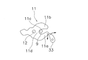
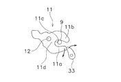
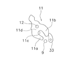
- FIG. 1 shows the outline of the opening-closing body opening / closing apparatus of one Embodiment in this invention. It is a block diagram which shows the structure of the control part about the opening / closing body opening / closing apparatus of FIG. It is a figure which shows the position state of the positional relationship in the latching and striker perfect engagement state about the locking mechanism used for the opening-and-closing body opening and closing apparatus of FIG. It is a figure which shows the position state of the positional relationship of a latch and striker in the state (1st state) in which the pole contact
- FIG. 1 is a diagram showing an outline of an opening / closing body opening / closing device.
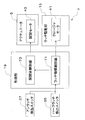
- FIG. 2 is a diagram illustrating a configuration of the control unit.
- the opening / closing body opening / closing device is a device for opening / closing the opening / closing body with respect to the opening member.
- the opening / closing body opening / closing device is the opening / closing body opening / closing device 100.
- the opening / closing body opening / closing device includes an opening member, an opening / closing body, a lock mechanism, and a control unit.
- An opening member is a member which has an opening part, and is the rear part 1 of the vehicle V in this embodiment.
- the opening member is a member capable of communicating one space with another space through the opening.
- the opening is an opening 1a that communicates the space inside the vehicle and the space outside the vehicle at the rear part of the vehicle V.
- the opening member may be a side part, an upper part of the vehicle, or a structure other than the vehicle. Examples of the structure other than the vehicle include a window and a door.
- the opening / closing body is a member that opens or closes the opening.
- the closed state may be a state in which at least a part of the opening of the opening is closed by the opening / closing body for a desired purpose, and the entire opening may not be closed.
- the open state does not need to be fully open as long as the opening of the opening is secured in a desired size.
- the opening / closing body is the back door 3 for opening or closing the opening 1a of the vehicle V.
- the opening / closing body may be an opening / closing type wall (door) that separates one space from another space.
- the opening / closing body may be a slide door that is disposed on at least one side surface of the vehicle V and opens / closes the side surface of the vehicle V, or may be a window glass attached to the door.
- the opening / closing body may be a trunk, a bonnet, a sunroof or the like in addition to the door.
- the opening / closing body can be a shoji.
- the opening / closing body opening / closing device may include an opening / closing drive unit.
- the opening / closing drive unit is a device that performs opening and closing operations of the opening / closing body.
- the opening operation refers to moving the opening / closing body whose opening is closed to a position where the opening is open.
- the closing operation refers to moving the opening / closing body having the opening in the open state to a position where the opening is in the closed state.
- the opening operation and the closing operation may be performed by an opening / closing drive unit or may be performed manually.
- the opening / closing drive unit includes an actuator 5 that can extend and contract in the length direction.
- the lower end of the actuator 5 is connected to the rear end of the inside of the vehicle V, and the upper end is connected to the inside of the vehicle V of the back door 3.
- the actuator 5 can move the back door 3 by expansion and contraction in the length direction, and can move the back door 3 between the closed state and the open state.
- One actuator 5 may be arranged on each of the left and right sides of the vehicle V and the back door 3, or one actuator 5 may be arranged in the center of the vehicle V and the back door 3. Further, two or more actuators 5 may be arranged.
- the lock mechanism is a mechanism provided for restricting movement of the opening / closing body in a closed state with respect to the opening. More specifically, the closed opening / closing body is locked with respect to the opening to maintain the closed state, and the opening / closing body is moved from the opening to lock the opening. It is a mechanism to release.
- the lock mechanism includes an engagement portion, an engaged portion, and an engagement drive portion.
- the locking mechanism is a latch mechanism 7.
- the engaging portion is a member that can be engaged with the engaged portion.
- the engaging portion is provided on one of the opening member and the opening / closing portion.
- the engaging portion is a latch 11.
- the latch 11 is provided at an inner lower portion when the opening 1a of the back door 3 is in a closed state so as to be rotatable between an engaged position and an engaged position.
- the engaged portion is a member that can be engaged with the engaging portion.
- the engaged portion is provided on the other of the opening and the opening / closing body.
- the engaged portion is a striker 9.
- the striker 9 is provided on the lower rear side of the vehicle V at a position where the latch 11 provided on the back door 3 can be engaged in the closed state.
- the striker 9 may be provided on the back door 3 and the latch 11 may be provided on the vehicle V.
- the engagement drive unit is a mechanism that performs an engagement operation and a release operation for the engagement between the engagement portion and the engaged portion.
- the engagement drive unit is a latch drive unit 15 (FIG. 2), and performs an engagement operation and a release operation of the latch 11 and the striker 9.
- the latch drive unit 15 includes a closure motor 41 and rotates the latch 11 as described later. As for the latch 11, the rotation is controlled by the closure motor 41 rotating a pole 33 (described later).
- the control unit controls the engagement operation and the release operation by the engagement drive unit.
- the control unit is the control unit 19 (FIG. 2).
- the control unit 19 controls the engagement operation and the release operation by the latch drive unit 15. The configuration of the control unit 19 will be described later.
- the control unit determines that the opening / closing body is in an open operation disabled state
- the control unit causes the engagement drive unit to perform a repeated operation in which the engagement operation and the release operation are alternately repeated.
- the inoperable state refers to a state in which the opening / closing body cannot be moved.
- the engagement drive unit releases the engagement between the engagement portion and the engaged portion. Usually caused by results that are not possible.
- the engagement operation is an operation in which the engagement drive unit moves the engagement unit to engage the engagement unit with the engaged unit.
- the release operation is an operation in which the engagement drive unit moves the engagement unit to release the engagement between the engagement unit and the engaged portion.
- the engagement part drive part cannot release the engagement between the engagement part and the engaged part
- the engaging portion cannot be moved to the target position, that is, the moving range of the engaging portion is limited.
- the closed inoperable state occurs when the engaging portion and the engaged portion are frozen, rusted, or the like, and an external environment or the like acts to fix the lock mechanism.
- water may enter and be present in the surroundings. In this case, the surroundings of the latch 11 and the striker 9 are frozen as the ambient temperature decreases.
- a minute gap between the latch 11 and the striker 9 is frozen, and the latch 11 and the striker 9 are in an integrated state.
- the presence of ice or rust in the movement direction of the latch 11 limits the movement range of the latch 11.
- rust may be generated depending on the material of the latch 11 and the striker 9, and the latch 11 and the striker 9 may be coupled by rust. In this case, the movement of the latch 11 is restricted, and the engagement between the latch 11 and the striker 9 cannot be released.
- the control unit 19 determines that the back door 3 cannot be opened, the control unit 19 causes the latch drive unit 15 to repeatedly perform an engagement operation and a release operation.
- the sticking in the engaged state between the latch 11 and the striker 9 can be efficiently eliminated.
- the latch 11 cannot be moved at all due to ice or rust, the ice or rust is distorted by applying stress to the ice or rust during the engagement operation. Since stress in the opposite direction to the operation is applied, distortion in the opposite direction occurs before the strain due to the engagement operation is relieved, so ice and rust are destroyed as a result of repeated engagement and release operations. Then, the adhesion between the latch 11 and the striker 9 can be eliminated.
- alternately repeating the engagement operation and the release operation may include at least one engagement operation and at least one release operation, and the order and combination of the engagement operation and the release operation are not particularly limited.
- the operation may be performed in the order of the engagement operation and the release operation, or the operation may be performed in the order of the release operation and the engagement operation.
- performing one release operation after two engagement operations is included in alternately repeating the engagement operation and the release operation.
- the engagement operation and the release operation may be performed so that the release operation includes a plurality of times including the release operation when determining that the release is impossible.
- the load applied to the motor of the engagement drive unit is reduced.
- the load applied to the closure motor 41 of the latch drive unit 15 is reduced. This is because, unlike the conventional case, the release operation is not performed for a long time in a state where the engaging portion and the engaged portion are locked in the engaged state, and an excessive current does not flow to the motor. is there.
- the latch mechanism 7 As the latch mechanism 7, a known latch mechanism used in a back door lock mechanism can be used. As described above, the latch mechanism 7 includes the latch 11 and the striker 9. As shown in FIGS. 3 to 6, the latch 11 is a member having a substantially U-shape when viewed from the side. More specifically, the latch 11 is configured such that the first arm 11a and the second arm 11b have a certain distance from the base portion 11d and protrude in substantially the same direction. Therefore, the concave portion 11c is formed by the first arm 11a, the second arm 11b, and the base portion 11d.
- the striker 9 is a member having a rod-shaped portion, and is formed so that the rod-shaped portion can be inserted into the recess 11c.
- the latch 11 is engaged completely so that the striker 9 inserted into the recess 11c cannot be detached from the position (FIG. 6) where the striker 9 is not inserted into the recess 11c.
- the rotary shaft 12 is pivotally supported so as to reciprocate between the position (FIG. 3). Further, between the position where the engagement is released and the position where the engagement is complete, the detachable state (FIG. 5) in which the engagement force between the latch 11 and the striker 9 is weaker than that in the complete engagement state. A position is provided.
- the insertion amount of the striker 9 into the recessed portion 11c is smaller than that in the fully engaged state, and more specifically, the opening of the recessed portion 11c is smaller than that in the fully engaged state. It is located on the side.
- the position of the latch 11 in the fully engaged state may be referred to as a full latch position
- the position of the latch 11 in the detachable state may be referred to as a half latch position
- the position of the latch 11 in the disengaged state may be referred to as an unlatched position.
- FIG. 4 shows a state in which the latch 11 is rotated by a predetermined angle from a position where the latch 11 is completely engaged to a position where the latch 11 can be detached.
- the latch 11 is urged so as to rotate clockwise in FIGS. 3 to 6 by an urging member (not shown).
- the latch driving unit 15 has a pole 33.
- the pole 33 is a member for restricting and releasing the clockwise rotation of the latch 11 in FIGS. 3 to 6.
- the rotation of the latch 11 in the clockwise direction is limited by the tip of the pole 33 coming into contact with the tips of the first arm 11a and the second arm 11b. That is, the frictional force generated when the tip of the pole 33 comes into contact with the tips of the first arm 11a and the second arm 11b, or the stopper of the pole 33 that restricts the rotation of the latch 11, The rotation of the latch 11 in the clockwise direction is restricted.
- the pole 33 is attached to a latch mechanism base (not shown) in the vicinity of the latch 11 so as to be rotatable in the clockwise direction in the drawing.
- the pole 33 is provided in the vicinity of the latch 11, a first position (FIG. 3) where the tip of the pole 33 abuts on the tip of the first arm 11a to limit the rotation of the latch 11, and the tip of the second arm 11b. Between the third position where the tip of the pole 33 abuts (FIG. 5) and the fourth position where the tip of the pole 33 abuts neither the tip of the first arm 11a nor the second arm 11b (FIG. 6). Moving. The latch 11 is in the full latch position when the pole 33 is in the first position, is in the half latch position when the pole 33 is in the third position, and is in the unlatched position when the pole 33 is in the fourth position. .
- the latch drive unit 15 includes a closure motor 41 (FIG.
- a drive transmission mechanism for example, a pinion gear, a sector gear, and a pole rotation mechanism fixed to the rotation output shaft.
- the pawl 33 is in contact with the first arm 11 a of the latch 11, thereby restricting the rotation of the latch 11 in the disengaged state. That is, the rotation of the latch 11 is restricted by the pole 33.
- the opening 1 a is closed by the back door 3.
- the latch 11 is in a state in which the striker 9 is housed in the recess 11c of the latch 11, and is fixed against the biasing force at a rotation angle at which the striker 9 is not detached from the opening side of the recess 11c of the latch 11. Is done. Thereby, even if the striker 9 and the latch 11 will be in a complete engagement state and the opening operation of the back door 3 is performed, it can prevent that the back door 3 opens.
- the rotation of the latch 11 is not restricted, so that the latch 11 is a biasing member (not shown). It is rotated to a predetermined angle by the urging force. At this time, the pole 33 is in contact with the first arm 11a of the latch 11, but the force by which the first arm 11a pushes the pole 33 by the urging force acting on the latch 11 is smaller than in the fully engaged state. is there. That is, the latch 11 and the striker 9 are engaged with each other with a predetermined engagement force that is weaker than that in the fully engaged state inside the recess 11 c of the latch 11.
- the latch 11 is rotated to a larger predetermined angle. At this time, the pole 33 contacts the second arm 11b of the latch 11, and the latch 11 stops at the half latch position. In such a contact state, the engagement force between the striker 9 and the latch 11 (the force by which the second arm 11b pushes the pole 33) is even smaller than that in the contact state of FIG.
- the latch 11 When the pole 33 is rotated to the fourth position shown in FIG. 6, the latch 11 is rotated to the fully open position.
- the striker 9 can freely enter and exit the recess 11c of the latch 11 (disengaged state). That is, the back door 3 can be freely opened and closed.
- the rotation of the pole 33 from the third position to the fourth position may be performed by at least one of moving the latch driving unit 15 and the back door 3 in the opening operation direction.
- the engagement force between the striker 9 and the latch 11 is small, the engagement between the striker 9 and the latch 11 can also be released by moving the back door 3 in the opening operation direction.
- the rotation of the pole 33 from the third position to the fourth position is performed by both the movement of the latch drive unit 15 and the back door 3.
- the latch mechanism 7 has a half latch detection switch 35 as shown in FIG.
- the half latch detection switch 35 detects from the rotation angle of the latch 11 that the contact state between the latch 11 and the pole 33 has become the detachable state shown in FIG.
- a mechanical switch that is turned off (generates a neutral position return completion position detection signal) when the rotation angle of the latch 11 is in a detachable state can be used.
- the latch mechanism 7 has an unlatch detection switch 37 as shown in FIG.
- the unlatch detection switch 37 detects from the rotation angle of the latch 11 that the contact state between the latch 11 and the pole 33 is the disengaged state shown in FIG.
- a mechanical switch that is turned off when the rotation angle of the latch 11 reaches a predetermined rotation angle (generates a stop position detection signal during the turning operation) can be used.
- the control unit 19 is a microcomputer system including a CPU, a storage device such as a RAM and a ROM, various interfaces, and the like, such as an electronic control unit (ECU) of the vehicle V.
- the functions of the following elements may be realized as programs that can be executed on the ECU.
- the control unit 19 of this embodiment includes a latch mechanism control unit 71 and an opening / closing body control unit 73.
- the latch mechanism control unit 71 drives the latch 11 by driving the latch driving unit 15, that is, the closure motor 41 (details will be described later).
- the opening / closing body control unit 73 opens and closes the back door 3 by driving the actuator 5 that is the opening / closing drive unit, that is, the opening / closing motor 43 (FIG. 2).
- the control unit 19 opens or closes the back door 3 that is output from a switch (not shown) provided on the back door 3 or at least one of the keys that can command the opening and closing of the back door 3 wirelessly. Can be received.
- the latch mechanism control unit 71 is connected to the half latch detection switch 35 of the latch mechanism 7 and receives a signal from the half latch detection switch 35, so that the half latch detection switch 35 is in an ON state or an OFF state. Can be confirmed. Thereby, it can be confirmed whether the latch 11 is in the half latch state of FIG.
- the latch mechanism control unit 71 is connected to the unlatch detection switch 37 of the latch mechanism 7 and can confirm whether the switch of the unlatch detection switch 37 is in an ON state or an OFF state. Thereby, the latch mechanism control part 71 can confirm from the switch state of the unlatch detection switch 37 whether the latch 11 is a disengagement state of FIG.
- the latch mechanism control unit 71 supplies a motor control signal as a drive voltage to the closure motor 41 to control the rotation of the closure motor 41.
- a motor control signal for example, a voltage having a constant voltage value, a pulse width modulation (PWM) voltage, or the like can be used.
- PWM pulse width modulation
- the opening / closing body control unit 73 supplies a motor control signal as a drive voltage to the opening / closing motor 43 to control the rotation of the opening / closing motor 43.
- the opening / closing body control unit 73 starts driving the actuator 5 when receiving an opening / closing body drive start signal from the latch mechanism control unit 71.
- the motor control signal (drive voltage) output from the opening / closing body control unit 73 to the opening / closing motor 43 is a pulse-width modulated voltage.
- the present invention is not limited to this, and a voltage having a constant voltage value may be used as the drive voltage.
- the opening / closing body control unit 73 preferably outputs the same drive voltage to the two actuators 5. Thereby, since the two actuators 5 can be expanded and contracted at the same speed, the back door 3 can be moved stably.
- control part 19 may be comprised by microcomputer systems, such as one electronic control unit, and may be comprised by the some electronic control unit (microcomputer system).
- microcomputer system such as one electronic control unit
- the latch mechanism control unit 71 and the opening / closing body control unit 73 may be configured as individual electronic control units (microcomputer systems).
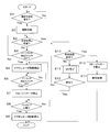
- FIG. 7 is a flowchart showing an opening operation of the opening / closing body opening / closing device.
- the control unit 19 checks whether or not a signal requesting an opening operation has been received (step S1).
- control unit 19 detects that a switch provided in the back door 3 or the vehicle is pressed, or a commanding device that can command the opening / closing of the back door 3 wirelessly with a signal requesting an opening operation (for example, , The remote controller attached to the key or the like), the control unit 19 can determine that the signal requesting the opening operation has been received.
- Step S1 When it is determined that the control unit 19 has not received a signal requesting an opening operation (“No” in Step S1), the control unit 19 waits until a signal requesting an opening operation is received. On the other hand, when it is determined that the control unit 19 has received a signal requesting an opening operation (“Yes” in step S1), the latch mechanism control unit 71 engages the closure motor 41 as an engagement release operation. A match release signal is output as a drive voltage to drive the latch mechanism 7 (rotate the latch 11) (step S2).
- the control unit opens and closes the lock mechanism when the engagement unit does not obtain information that the engagement unit has reached the neutral position that is the neutral position between the engagement position and the engagement release position during the engagement operation of the engagement unit.
- the body is determined to be inoperable.
- the engagement position is a full latch position
- the engagement release position is an unlatching position
- the neutral position is a half latch position.
- the control unit 19 determines that the back door 3 cannot be opened when the information that the latch 11 has reached the half latch position (FIG. 5) is not obtained.
- the information indicating that the half door position has been reached determines whether or not the back door 3 can be opened.
- the control unit 19 monitors whether or not the half latch detection switch 35 is in the OFF state before the predetermined time ta has elapsed.
- the fact that the half latch detection switch 35 does not enter the OFF state indicates that the above-mentioned “latch 11 has reached the neutral position (FIG. 5), which is the neutral position between the engagement position (FIG. 3) and the release position (FIG. 6). Corresponds to “When I didn't get it”.
- control unit 19 determines whether or not a predetermined time ta has elapsed since the engagement release signal was transmitted (step S3).
- the latch mechanism control unit 71 determines whether or not the switch state of the half latch detection switch 35 is OFF. Is monitored (step S4).
- step S3 determines that the predetermined time ta has elapsed (in the case of “Yes” in step S3).
- step S10 determines that the switch state of the half latch detection switch 35 is not OFF (in the case of “No” in step S4), the process returns to step S3.
- step S4 When the latch mechanism control unit 71 determines that the switch state of the half latch detection switch 35 is OFF (“Yes” in step S4), the latch mechanism control unit 71 causes the opening / closing body control unit 73 to drive the opening / closing body. Output a start signal. Next, the opening / closing body control unit 73 outputs a motor control signal to the opening / closing motor 43 of the actuator 5 to drive the actuator 5 (step S5).
- the latch mechanism control unit 71 monitors the switch state of the unlatch detection switch 37 and waits for the unlatch detection switch 37 to be turned off (step S6). If the unlatch detection switch 37 is turned off (“Yes” in step S6), it is determined that the engagement state between the latch 11 and the striker 9 is the disengagement state shown in FIG. 6, and the process proceeds to step S7. Proceed to The latch mechanism control unit 71 stops the closure motor 41 of the latch mechanism 7 (step S7).
- the opening / closing body control unit 73 monitors the switch state of a fully open detection switch (not shown) (step S8). When it is determined that the back door 3 has reached the fully open position (“Yes” in step S8), the opening / closing body control unit 73 stops driving the actuator 5 by stopping the output of the motor control signal. (Step S9). Then, the opening / closing body opening / closing device 100 ends the opening operation.
- the control unit 19 determines that the predetermined time ta has elapsed (in the case of “Yes” in step S3), the control unit 19 retries the motor engagement operation and the release operation, and the half latch detection switch 35 is turned off. Repeat until it becomes.
- control unit 19 determines whether or not the retry has been executed a predetermined number of times (step S10). If it is determined that the retry has not been executed a predetermined number of times, a retry operation is executed (step S11). Subsequently, the control unit 19 determines whether or not the retry is successful (step S12). The control unit 19 determines success if the information that the half latch detection switch 35 is OFF can be obtained, and determines failure if the information is not available. If unsuccessful, the process returns to step S10. If successful, the process moves to step S5.
- the control unit 19 stops the motor (step S13), and then executes an abnormality process (step S14).
- the abnormality process is, for example, generation of an abnormal signal.
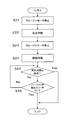
- the retry operation will be described with reference to FIG. FIG. 8 is a flowchart of the retry operation.
- the engagement operation and the release operation each end once before an excessive current flows through the engagement drive unit. As a result, it is possible to prevent the engagement drive unit from failing when the engagement between the engaging portion and the engaged portion cannot be eliminated.
- the engagement operation (step S22) and the release operation (step S24) are completed before an excessive current flows through the latch drive unit 15, respectively. As a result, it is possible to prevent the latch drive unit 15 from failing when the sticking cannot be resolved. That is, since an excessive load does not act on the latch driving unit 15, the life of the closure motor 41 is extended.
- the latch mechanism control unit 71 stops the closure motor 41 of the latch mechanism 7 (step S21), engages the closure motor 41 (step S22), and finally stops the engagement operation of the closure motor 41 (step S23). ).
- the engagement operation of the closure motor 41 is executed only for a predetermined time tc. Therefore, the engagement operation ends before an excessive current flows through the latch drive unit 15.
- the engagement operation specifically refers to applying to the closure motor 41 a drive voltage that generates torque in a direction in which the pole 33 rotates from the first position to the third position.
- the latch mechanism control unit 71 outputs an opening operation control signal as a drive voltage to the closure motor 41, and drives the latch mechanism 7 (rotates the latch 11) (step S24).
- the latch mechanism control unit 71 monitors whether or not the half latch detection switch 35 is turned off before the predetermined time tb elapses. Specifically, it is determined whether or not a predetermined time tb has elapsed (step S25). When the latch mechanism control unit 71 determines that the predetermined time tb has not elapsed (in the case of “No” in step S25), the latch mechanism control unit 71 sets the switch state of the half latch detection switch 35 to the OFF state. It is monitored whether or not (step S26). When the latch mechanism control unit 71 determines that the predetermined time tb has elapsed (in the case of “Yes” in step S25), the process ends with a retry failure. That is, even if the release operation is long, it is not executed beyond the predetermined time tb. Therefore, the release operation is completed before an excessive current flows through the latch drive unit 15.
- step S26 If the latch mechanism control unit 71 determines that the switch state of the half latch detection switch 35 is not OFF ("No" in step S26), the process returns to step S25. If the latch mechanism control unit 71 determines that the switch state of the half latch detection switch 35 is in the OFF state (in the case of “Yes” in step S26), the process ends with a retry being successful.
- the drive voltage output to the closure motor 41 as the release operation may be the same condition every time or may be a different condition as necessary.
- the drive voltage application time may be lengthened only for the first time.
- the drive voltage may be increased only for the first time, and in the case of a pulse width modulated motor control signal, the pulse period may be decreased only for the first time. As a result, the torque of the motor increases at the first time.
- the drive voltage may be increased or the pulse period may be reduced in the case of a pulse width modulated motor control signal.
- the torque of the motor gradually increases.
- the operation of each step is changed and / or the order of each step is within the scope of the present invention. You may make changes such as swapping.
- FIGS. 9 to 10 are timing charts showing the release operation of the latch drive section.
- FIG. 9 shows a case where the retry operation is not performed.
- Timing (c) The OFF state of the unlatch detection switch 37 is detected.
- step S2 the above-described operation is released at step S2 in FIG. 7, and the OFF state of the half latch detection switch 35 is detected at step S4 before the predetermined time ta elapses (FIG. 5).
- step S4 the OFF state of the unlatch detection switch 37 is detected in step S6 (FIG. 6), and the motor is stopped in step S7.
- the rotation of the pole 33 from the half latch position to the unlatch position is performed by both the latch drive unit 15 and the movement of the back door 3. Therefore, at timing (c), the closure motor 41 of the actuator 5 is driven in a direction for opening the back door 3. This also applies to the timing (o) when the retry operation described below is performed twice.
- FIG. 10 shows a case where the retry operation is performed twice.
- Timing (f) The release operation is started.
- Timing (l) The engagement operation is started.
- Timing (m) Since the predetermined time tc has elapsed, the motor is stopped.
- the engagement member in the engagement position means that the latch is in the full latch position
- the engagement member in the release position means that the latch is in the unlatching position
- the engagement member in the engagement position may mean that the latch is in the full latch position
- the engagement member in the release position may mean that the latch is in the half latch position.
- the engagement member in the engagement position means that the latch is in the half latch position
- the engagement member in the release position means that the engagement member is in the unlatching position. May be. This assumes, for example, a case where the latch is in contact with an obstacle such as ice at a half-latch position in the middle of moving from the full latch position and further movement is restricted.
- the opening / closing body opening / closing device may not include an opening / closing drive unit.
- the actuator 5 is operated from the half latch position. However, the actuator 5 may not be operated until the unlatched position, and the latch 11 may be moved to the unlatched position only by the latch driving unit.
- each switch only needs to be able to detect a desired state, the ON-OFF relationship may be reversed.
- the type of switch is not limited to the above embodiment.
- the present invention can be widely applied to an opening / closing body opening / closing device, in particular, an apparatus for opening / closing an opening / closing body such as a vehicle door.
Landscapes
- Engineering & Computer Science (AREA)
- Mechanical Engineering (AREA)
- Lock And Its Accessories (AREA)
Abstract
ロック機構の固着を容易に解消することができる開閉体開閉装置を提供することを目的とする。開閉体開閉装置100は、開口部1aを有する後部1と、開口部1aを開状態または閉状態とするバックドア3と、バックドア3の開作動および閉作動を行うアクチュエータ5と、後部1に設けられたストライカ9と、バックドア3に設けられてストライカ9に係合するラッチ11と、ストライカ9とラッチ11との係合作動および解除作動を行うラッチ駆動部15とを有するラッチ機構7と、ラッチ駆動部15による係合作動と解除作動とを制御する制御部19と、を備えている。制御部19は、バックドア3を開作動不能状態と判断したときに、ラッチ駆動部15が係合作動と解除作動とを交互に繰返して作動する繰返し作動を行わせる。
Description
本発明は、開閉体開閉装置に関する。
開閉駆動部や手動によって開閉体を駆動することにより、開口部を開状態または閉状態とする開閉装置が知られている。
この開閉装置を含む開閉機構としては、開閉駆動部や手動によって閉位置にまで移動された開閉体を、開閉体に設けられた係合部と開口部の周縁に設けられた被係合部とを係合させて、閉状態に維持するロック機構を備えるものがある。
この開閉装置を含む開閉機構としては、開閉駆動部や手動によって閉位置にまで移動された開閉体を、開閉体に設けられた係合部と開口部の周縁に設けられた被係合部とを係合させて、閉状態に維持するロック機構を備えるものがある。
このようなロック機構を備えた開閉機構は、開口部を開状態から閉状態にする際には、開閉駆動部や手動により開閉体を閉位置まで移動させ、ロック機構を閉作動させることで係合部と被係合部との係合をさせて、開口部を開閉体により閉状態とする。また、開口部を閉状態から開状態にする際には、ロック機構の解除動作によって、係合部と被係合部との係合を解除したうえで、開閉駆動部や手動により開閉体を移動させて、開口部を閉状態から開状態にする。
このような開口部を開状態とする開作動時においては、異物の挟み込みや気温の変化など外部環境等が開閉体に作用して、開閉駆動部の閉動作や開動作が阻害される場合がある。
このような開口部を開状態とする開作動時においては、異物の挟み込みや気温の変化など外部環境等が開閉体に作用して、開閉駆動部の閉動作や開動作が阻害される場合がある。
例えば、特許文献1には、開閉体の閉作動中に開閉体に所定以上の荷重が作用したとき、開閉体を開方向に駆動する自動反転を行うようにした車両用開閉体制御装置において、車両状況検出手段により所定状況が検出されたとき、自動反転を禁止する禁止手段、を備えている車両用開閉体制御装置が開示されている。
このような制御は、開閉体の挟み込みのような外部環境等が開閉体に直接作用する場合に対応している。しかし、開閉体については、水分などの外部環境が開閉体に直接作用するのではなく、係合部と被係合部とが凍りつきや錆などにより、外部環境等が作用してロック機構が固着する場合もある。このような、ロック機構の固着が生じると、開閉体の開閉作動に支障をきたすこととなってしまう。
本発明の目的は、ロック機構の固着を容易に解消することができる開閉体開閉装置を提供することにある。
本発明の開閉体開閉装置は、開口部材と、開閉体と、ロック機構と、制御部とを備えている。
開口部材は、開口部を有する。
開閉体は、開口部を開状態または閉状態とする。
ロック機構は、開口部材及び開閉体の一方に設けられた係合部と、開閉体及び開口部材の他方に設けられて係合部に係合する被係合部と、係合部と被係合部との係合作動および解除作動を行う係合駆動部とを有する。
制御部は、係合駆動部による係合作動と解除作動とを制御する。
制御部は、開閉体を開作動不能状態と判断したときに、係合駆動部が係合作動と解除作動とを交互に繰り返して作動する繰返し作動を行わせる。
開口部材は、開口部を有する。
開閉体は、開口部を開状態または閉状態とする。
ロック機構は、開口部材及び開閉体の一方に設けられた係合部と、開閉体及び開口部材の他方に設けられて係合部に係合する被係合部と、係合部と被係合部との係合作動および解除作動を行う係合駆動部とを有する。
制御部は、係合駆動部による係合作動と解除作動とを制御する。
制御部は、開閉体を開作動不能状態と判断したときに、係合駆動部が係合作動と解除作動とを交互に繰り返して作動する繰返し作動を行わせる。
本発明の開閉体開閉装置によれば、係合部と被係合部との係合状態での固着を効率的に解消できうる。
1.第1実施形態
(1)開閉体開閉装置の概略
以下、図1及び図2を参照して、本発明の第1実施形態の開閉体開閉装置を説明する。図1は、開閉体開閉装置の概略を示す図である。図2は、制御部の構成を示す図である。
(1)開閉体開閉装置の概略
以下、図1及び図2を参照して、本発明の第1実施形態の開閉体開閉装置を説明する。図1は、開閉体開閉装置の概略を示す図である。図2は、制御部の構成を示す図である。
開閉体開閉装置は、開口部材に対して開閉体を開閉する装置である。この実施形態では、開閉体開閉装置は、開閉体開閉装置100である。
開閉体開閉装置は、開口部材と、開閉体と、ロック機構と、制御部とを備えている。
開口部材は、開口部を有する部材であり、この実施形態では、車両Vの後部1である。開口部材は、開口部を介して1つの空間と他の空間とを連通可能な部材である。この実施形態では、開口部は、車内の空間と車外の空間とを車両Vの後部で連通する開口部1aである。開口部材は、車両の側部、上部、又は車両以外の構造であってもよい。車両以外の構造としては、例えば窓やドアなどが挙げられる。
開口部材は、開口部を有する部材であり、この実施形態では、車両Vの後部1である。開口部材は、開口部を介して1つの空間と他の空間とを連通可能な部材である。この実施形態では、開口部は、車内の空間と車外の空間とを車両Vの後部で連通する開口部1aである。開口部材は、車両の側部、上部、又は車両以外の構造であってもよい。車両以外の構造としては、例えば窓やドアなどが挙げられる。
開閉体は、開口部を開状態または閉状態とする部材である。閉状態は、所望の目的で、開口部の開口の少なくとも一部が開閉体により塞がれた状態であればよく、開口部全てが塞がれていなくてもよい。また、開状態についても、所望の大きさで開口部の開口が確保されていれば、全開である必要もない。この実施形態では、開閉体は、車両Vの開口部1aを開状態または閉状態とするためのバックドア3である。開閉体は、1つの空間を他の空間から隔てる開閉式の壁(ドア)であればよい。したがって、開閉体の他の例としては、車両Vの少なくとも1つの側面に配置され、車両Vの側面の開閉を行うスライドドアであってもよいし、ドアに取り付けられる窓ガラスであってもよい。開閉体は、ドア以外に、トランク、ボンネット、サンルーフなどでもよい。また、開口部材が窓の場合、開閉体は障子とすることができる。
開閉体開閉装置は、開閉駆動部を備えてもよい。開閉駆動部は、開閉体の開作動および閉作動を行う装置である。開作動とは、開口部を閉状態としている開閉体を、開口部が開状態となる位置まで移動させることをいう。また、閉作動とは、開口部を開状態としている開閉体を、開口部が閉状態となる位置まで移動させることをいう。開作動及び閉作動は、開閉駆動部により行われてもよく、手動により行われてもよい。この実施形態では、開閉駆動部は、長さ方向に伸縮可能なアクチュエータ5を含む。アクチュエータ5は、例えば、長さ方向の下端が車両Vの内部の後部端に接続され、上端がバックドア3の車両Vの内部側に接続される。これにより、アクチュエータ5は、長さ方向の伸縮によりバックドア3を移動可能となり、バックドア3を閉状態と開状態との間に移動できる。
なお、アクチュエータ5は、車両V及びバックドア3の左右両側に1つずつ配置されてもよいし、車両V及びバックドア3の中央に1つ配置されていてもよい。さらに、アクチュエータ5は2以上配置されていてもよい。
なお、アクチュエータ5は、車両V及びバックドア3の左右両側に1つずつ配置されてもよいし、車両V及びバックドア3の中央に1つ配置されていてもよい。さらに、アクチュエータ5は2以上配置されていてもよい。
ロック機構は、開口部に対して開閉体を閉状態で移動規制するために設けられる機構である。より詳細には、閉状態の開閉体を開口部に対してロックして閉状態を維持し、開閉体を開口部から移動させることで開口部を閉状態から開状態にしようとするときにロックを解除する機構である。ロック機構は、係合部と、被係合部と、係合駆動部とを有する。この実施形態では、ロック機構は、ラッチ機構7である。
係合部は、被係合部との係合が可能な部材である。係合部は、開口部材及び開閉部の一方に設けられている。この実施形態では、係合部は、ラッチ11である。ラッチ11は、バックドア3の開口部1aを閉状態とした場合における内側下部に、係合位置と被係合位置との間を回動可能となるように設けられている。
被係合部は、係合部との係合が可能な部材である。被係合部は、開口部及び開閉体の他方に設けられている。この実施形態では、被係合部は、ストライカ9である。ストライカ9は、車両Vの後部下側において、バックドア3に設けられたラッチ11が閉状態において係合することが可能な位置に設けられている。
なお、ストライカ9がバックドア3に設けられ、ラッチ11が車両Vに設けられていてもよい。この実施形態におけるラッチ11とストライカ9との詳細については、後述するが、ラッチ11とストライカ9とには、公知の構成の物を用いることができる。
係合部は、被係合部との係合が可能な部材である。係合部は、開口部材及び開閉部の一方に設けられている。この実施形態では、係合部は、ラッチ11である。ラッチ11は、バックドア3の開口部1aを閉状態とした場合における内側下部に、係合位置と被係合位置との間を回動可能となるように設けられている。
被係合部は、係合部との係合が可能な部材である。被係合部は、開口部及び開閉体の他方に設けられている。この実施形態では、被係合部は、ストライカ9である。ストライカ9は、車両Vの後部下側において、バックドア3に設けられたラッチ11が閉状態において係合することが可能な位置に設けられている。
なお、ストライカ9がバックドア3に設けられ、ラッチ11が車両Vに設けられていてもよい。この実施形態におけるラッチ11とストライカ9との詳細については、後述するが、ラッチ11とストライカ9とには、公知の構成の物を用いることができる。
係合駆動部は、係合部と被係合部との係合について係合作動および解除作動を行う機構である。この実施形態では、係合駆動部はラッチ駆動部15(図2)であり、ラッチ11とストライカ9との係合作動及び解除作動を行う。具体的には、ラッチ駆動部15は、後述するように、クロージャモータ41を有しており、ラッチ11を回動させる。ラッチ11については、クロージャモータ41がポール33(後述)を回動することで、回動が制御されている。
制御部は、係合駆動部による係合作動と解除作動とを制御する。この実施形態では、制御部は制御部19(図2)である。制御部19は、ラッチ駆動部15による係合作動と解除作動とを制御する。制御部19の構成については、後述する。
制御部は、係合駆動部による係合作動と解除作動とを制御する。この実施形態では、制御部は制御部19(図2)である。制御部19は、ラッチ駆動部15による係合作動と解除作動とを制御する。制御部19の構成については、後述する。
制御部は、開閉体を開作動不能状態と判断したときに、係合駆動部が係合作動と解除作動とを交互に繰返して作動する繰返し作動を行わせる。
開作動不能状態とは、開閉体を移動できない状態のことをいい、開口部を閉状態から開状態にする際において、係合駆動部が係合部と被係合部との係合を解除できない結果により生じるのが通常である。
係合作動とは、係合駆動部が係合部を移動させて、係合部を被係合部に係合させようとする動作である。
解除作動とは、係合駆動部が係合部を移動させて、係合部と被係合部との係合を解除しようとする動作である。
係合部駆動部が係合部と被係合部との係合を解除できない場合としては、(1)係合駆動部が係合部を全く移動できない場合、(2)係合部を移動できるが、係合部を目標の位置まで移動できない場合、すなわち係合部の移動範囲が制限されている場合を挙げることができる。上述したように、閉作動不能状態は、係合部と被係合部とが凍りつきや錆などにより、外部環境等が作用してロック機構が固着することなどにより生じる。例えば、ラッチ11とストライカ9とが係合した状態において水が進入して周囲に存在することがある。この場合、周囲の温度が低下することによって、ラッチ11とストライカ9の周囲が氷結する。これにより、例えば、ラッチ11とストライカ9との間の微小な隙間が氷結してラッチ11とストライカ9とがいわば一体化した状態となる。また、ラッチ11の移動方向に氷や錆が存在したりすることで、ラッチ11の移動範囲が制限されたりする。また、水分が進入したまま長期間放置することで、ラッチ11とストライカ9との材質によっては錆が発生し、ラッチ11とストライカ9とが錆びにより結合したりしうる。この場合、ラッチ11の移動が制限され、ラッチ11とストライカ9との係合を解除できない。
開作動不能状態とは、開閉体を移動できない状態のことをいい、開口部を閉状態から開状態にする際において、係合駆動部が係合部と被係合部との係合を解除できない結果により生じるのが通常である。
係合作動とは、係合駆動部が係合部を移動させて、係合部を被係合部に係合させようとする動作である。
解除作動とは、係合駆動部が係合部を移動させて、係合部と被係合部との係合を解除しようとする動作である。
係合部駆動部が係合部と被係合部との係合を解除できない場合としては、(1)係合駆動部が係合部を全く移動できない場合、(2)係合部を移動できるが、係合部を目標の位置まで移動できない場合、すなわち係合部の移動範囲が制限されている場合を挙げることができる。上述したように、閉作動不能状態は、係合部と被係合部とが凍りつきや錆などにより、外部環境等が作用してロック機構が固着することなどにより生じる。例えば、ラッチ11とストライカ9とが係合した状態において水が進入して周囲に存在することがある。この場合、周囲の温度が低下することによって、ラッチ11とストライカ9の周囲が氷結する。これにより、例えば、ラッチ11とストライカ9との間の微小な隙間が氷結してラッチ11とストライカ9とがいわば一体化した状態となる。また、ラッチ11の移動方向に氷や錆が存在したりすることで、ラッチ11の移動範囲が制限されたりする。また、水分が進入したまま長期間放置することで、ラッチ11とストライカ9との材質によっては錆が発生し、ラッチ11とストライカ9とが錆びにより結合したりしうる。この場合、ラッチ11の移動が制限され、ラッチ11とストライカ9との係合を解除できない。
この実施形態では、制御部19は、バックドア3を開作動不能状態と判断したときに、ラッチ駆動部15が係合作動と解除作動とを交互に繰り返して作動する繰返し作動を行わせる。この結果、ラッチ11とストライカ9との係合状態での固着を効率的に解消できうる。例えば、氷や錆によりラッチ11を全く移動できなくても、係合作動で氷や錆に応力が加わることで氷や錆に歪が生じ、更に、短い時間を置いた後に解除動作によって係合動作と反対方向の応力が加わるために、係合作動による歪が緩和される前に反対方向への歪が生じるため、係合作動と解除作動との繰り返しの結果として氷や錆が破壊されて、ラッチ11とストライカ9との固着が解消されうる。また、ラッチ11の移動範囲が制限されていても、解除作動を行うことで、移動方向に存在する氷や錆に、微小であっても、衝撃を加えることができ、この衝撃により氷や錆を破壊することで、ラッチ11の移動範囲の制限が解消されうる。この際、係合作動も行うことで、解除作動の際に氷や錆に与える衝撃を与えることもできる。このように、ラッチ駆動部15が係合作動後に解除作動を行うことを繰り返すことで、固着部分に複数回の応力の付加を与えることや、氷や錆に複数回の衝撃を与えることができるので、閉作動不能状態を効果的に解消しうる。
なお、係合作動と解除作動とを交互に繰り返すとは、少なくとも1回の係合作動と少なくとも1回の解除作動とを含めばよく、係合作動と解除作動の順序及び組み合わせは特に限定されない。例えば、係合作動と解除作動の順序で動作が行われてもよいし、解除作動と係合作動の順序で動作が行われてもよい。また、2回の係合作動の後に1回の解除作動を行うことなども、係合作動と解除作動とを交互に繰り返すことに含まれる。解除不能状態と判断する際の解除作動を含めて、解除作動が複数回含むように、係合作動と解除作動とが行われてもよい。
また、本実施形態では、係合駆動部のモータへかかる負荷が軽減される。この実施形態では、ラッチ駆動部15のクロージャモータ41へかかる負荷が低減される。これは、従来とは異なり、係合部と被係合部との係合状態での固着がある状態で解除作動が長時間にわたって実行されることがなく、モータに過大電流が流れないからである。
(2)ラッチ機構の詳細構成
ラッチ機構7の詳細を説明する。ラッチ機構7としてはバックドアのロック機構において用いられる公知のラッチ機構を用いることができ、上述したように、ラッチ機構7は、ラッチ11とストライカ9とを備える。ラッチ11は、図3~図6に示すように、側面から見た形状が略U字形状の部材である。より詳細には、ラッチ11は、第1アーム11aと、第2アーム11bとが基部11dから一定の間隔を有し、かつ、略同方向に突出するように構成されている。よって、第1アーム11aと、第2アーム11bと、基部11dにより凹部11cが形成される。ストライカ9は、ここでは棒状の部分を有する部材であり、この棒状の部分が凹部11cに挿入可能なように形成されている。
ラッチ11は、凹部11cにストライカ9が挿入されない状態である係合解除状態となる位置(図6)と、凹部11cに挿入されたストライカ9を凹部11cから離脱できないように係合する完全係合状態となる位置(図3)との間を往復できるように、回動軸12に軸支されている。また、係合解除状態となる位置と完全係合状態となる位置との間には、ラッチ11とストライカ9との係合力が、完全係合状態よりも弱い脱離可能状態(図5)となる位置が設けられている。なお、ここでの脱離可能状態は、凹部11cへのストライカ9の挿入量が完全係合状態よりも少なくなっており、より具体的には、ストライカ9が完全係合状態よりも凹部11c開口側に位置することをいう。また、以下では、完全係合状態のラッチ11の位置をフルラッチ位置、脱離可能状態のラッチ11の位置をハーフラッチ位置、係合解除状態のラッチ11の位置をアンラッチ位置という場合がある。
なお、図4はラッチ11が完全係合状態となる位置から脱離可能状態となる位置までの間で所定角度回動した状態を示している。
また、ラッチ11は、付勢部材(図示せず)により図3~図6において、時計回りに回動するように付勢されている。
ラッチ機構7の詳細を説明する。ラッチ機構7としてはバックドアのロック機構において用いられる公知のラッチ機構を用いることができ、上述したように、ラッチ機構7は、ラッチ11とストライカ9とを備える。ラッチ11は、図3~図6に示すように、側面から見た形状が略U字形状の部材である。より詳細には、ラッチ11は、第1アーム11aと、第2アーム11bとが基部11dから一定の間隔を有し、かつ、略同方向に突出するように構成されている。よって、第1アーム11aと、第2アーム11bと、基部11dにより凹部11cが形成される。ストライカ9は、ここでは棒状の部分を有する部材であり、この棒状の部分が凹部11cに挿入可能なように形成されている。
ラッチ11は、凹部11cにストライカ9が挿入されない状態である係合解除状態となる位置(図6)と、凹部11cに挿入されたストライカ9を凹部11cから離脱できないように係合する完全係合状態となる位置(図3)との間を往復できるように、回動軸12に軸支されている。また、係合解除状態となる位置と完全係合状態となる位置との間には、ラッチ11とストライカ9との係合力が、完全係合状態よりも弱い脱離可能状態(図5)となる位置が設けられている。なお、ここでの脱離可能状態は、凹部11cへのストライカ9の挿入量が完全係合状態よりも少なくなっており、より具体的には、ストライカ9が完全係合状態よりも凹部11c開口側に位置することをいう。また、以下では、完全係合状態のラッチ11の位置をフルラッチ位置、脱離可能状態のラッチ11の位置をハーフラッチ位置、係合解除状態のラッチ11の位置をアンラッチ位置という場合がある。
なお、図4はラッチ11が完全係合状態となる位置から脱離可能状態となる位置までの間で所定角度回動した状態を示している。
また、ラッチ11は、付勢部材(図示せず)により図3~図6において、時計回りに回動するように付勢されている。
ラッチ駆動部15は、ポール33を有している。ポール33は、ラッチ11の図3~図6において、時計回りの回動を制限及び制限解除するための部材である。ラッチ11の時計回り方向への回動は、ポール33の先端が第1アーム11aおよび第2アーム11bの先端に当接することで制限される。すなわち、ポール33の先端が第1アーム11aおよび第2アーム11bの先端に当接することで発生する摩擦力や、ポール33の先端がラッチ11の回動を規制する当止めとなることなどで、ラッチ11の時計回り方向への回動が規制される。ポール33は、ラッチ11の近傍にラッチ機構基体(図示せず)に図中時計回り方向へ回動可能に取り付けられている。ポール33は、ラッチ11の近傍に設けられ、第1アーム11aの先端にポール33の先端が当接してラッチ11の回動を制限する第1位置(図3)と、第2アーム11bの先端にポール33の先端が当接する第3位置(図5)と、ポール33の先端が第1アーム11aおよび第2アーム11bの先端のいずれとも当接しない第4位置(図6)との間を移動する。ラッチ11は、ポール33が第1位置にあるときはフルラッチ位置であり、ポール33が第3位置にあるときはハーフラッチ位置であり、ポール33が第4位置にあるときは、アンラッチ位置である。ラッチ駆動部15は、ポール33を回動するためのクロージャモータ41(図2)及び駆動伝達機構(例えば、回転出力軸に固定されたピニオンギア、セクタギア、ポール回動機構)を有している。
バックドア3を開状態にしようとするとき、ポール33は、クロージャモータ41により図3~図6において、時計回りに、つまりポール33と第1アーム11aとの当接が解除される方向に回転される。その結果、ラッチ11は時計回りに回転されて、ラッチ11とストライカ9との係合状態が、図3の完全係合状態から図6の係合解除状態へと遷移する。
バックドア3を開状態にしようとするとき、ポール33は、クロージャモータ41により図3~図6において、時計回りに、つまりポール33と第1アーム11aとの当接が解除される方向に回転される。その結果、ラッチ11は時計回りに回転されて、ラッチ11とストライカ9との係合状態が、図3の完全係合状態から図6の係合解除状態へと遷移する。
以下、ポール33の位置とラッチ11の位置関係を説明する。
ポール33は、図3に示す第1位置にあるときには、ラッチ11の第1アーム11aに当接することで、ラッチ11の係合解除状態の方向への回動を制限する。つまり、ラッチ11はポール33によって回動を制限されている。このとき、開口部1aは、バックドア3により塞がれて閉状態となっている。そして、ラッチ11は、ラッチ11の凹部11cにストライカ9が収納された状態であって、ストライカ9がラッチ11の凹部11cの開口側から離脱しない回動角度に、上記の付勢力に逆らって固定される。これにより、ストライカ9とラッチ11とが完全係合状態となり、仮にバックドア3の開作動が行われたとしても、バックドア3が開くのを防止できる。
ポール33は、図3に示す第1位置にあるときには、ラッチ11の第1アーム11aに当接することで、ラッチ11の係合解除状態の方向への回動を制限する。つまり、ラッチ11はポール33によって回動を制限されている。このとき、開口部1aは、バックドア3により塞がれて閉状態となっている。そして、ラッチ11は、ラッチ11の凹部11cにストライカ9が収納された状態であって、ストライカ9がラッチ11の凹部11cの開口側から離脱しない回動角度に、上記の付勢力に逆らって固定される。これにより、ストライカ9とラッチ11とが完全係合状態となり、仮にバックドア3の開作動が行われたとしても、バックドア3が開くのを防止できる。
ポール33が図4のように第1位置と第3位置との間の第2位置に回動すると、ラッチ11の回動が制限されなくなるため、ラッチ11は付勢部材(図示せず)の付勢力によって所定角度まで回動する。このとき、ポール33がラッチ11の第1アーム11aに当接しているが、ラッチ11に働く付勢力により第1アーム11aがポール33を押す力は、完全係合状態よりも小さくなった状態である。すなわち、ラッチ11とストライカ9が、ラッチ11の凹部11cの内部にて完全係合状態のときよりも弱い所定の係合力にて係合している状態である。
ポール33が図5の第3位置に回動すると、ラッチ11はさらに大きな所定角度まで回動する。このとき、ポール33はラッチ11の第2アーム11bと当接し、ラッチ11はハーフラッチ位置で停止する。このような当接状態においては、ストライカ9とラッチ11との係合力(第2アーム11bがポール33を押す力)は、図4の当接状態の時よりもさらに小さい。
ポール33が図5の第3位置に回動すると、ラッチ11はさらに大きな所定角度まで回動する。このとき、ポール33はラッチ11の第2アーム11bと当接し、ラッチ11はハーフラッチ位置で停止する。このような当接状態においては、ストライカ9とラッチ11との係合力(第2アーム11bがポール33を押す力)は、図4の当接状態の時よりもさらに小さい。
ポール33が図6に示す第4位置に回動すると、ラッチ11は全開位置まで回動する。ラッチ11が全開位置の回動角度にあるとき、ストライカ9は、ラッチ11の凹部11cに出入り自由となる(係合解除状態)。すなわち、バックドア3が開閉自由に回動可能となる。
第3位置から第4位置へのポール33の回動は、ラッチ駆動部15およびバックドア3を開作動方向へ移動させることの少なくとも一方により行われることが挙げられる。上述したように、ストライカ9とラッチ11との係合力は小さいため、バックドア3を開作動方向へ移動させることでも、ストライカ9とラッチ11との係合を解除することができる。なお、後述するように、この実施形態では、第3位置から第4位置へのポール33の回動は、ラッチ駆動部15とバックドア3の移動との両方により行われる。ラッチ駆動部については、ラッチ11を回動させることでストライカ9とラッチ11との係合解除をすることにより、係合作動と解除作動とをさせてもよい。
第3位置から第4位置へのポール33の回動は、ラッチ駆動部15およびバックドア3を開作動方向へ移動させることの少なくとも一方により行われることが挙げられる。上述したように、ストライカ9とラッチ11との係合力は小さいため、バックドア3を開作動方向へ移動させることでも、ストライカ9とラッチ11との係合を解除することができる。なお、後述するように、この実施形態では、第3位置から第4位置へのポール33の回動は、ラッチ駆動部15とバックドア3の移動との両方により行われる。ラッチ駆動部については、ラッチ11を回動させることでストライカ9とラッチ11との係合解除をすることにより、係合作動と解除作動とをさせてもよい。
ラッチ機構7は、図2に示すように、ハーフラッチ検出スイッチ35を有している。ハーフラッチ検出スイッチ35は、ラッチ11とポール33との当接状態が図5に示す脱離可能状態となったことを、ラッチ11の回動角度から検知する。ハーフラッチ検出スイッチ35としては、ラッチ11の回動角度が脱離可能状態となった時にOFFとなる(中立位置戻し完了位置検出信号を発生する)メカニカルスイッチを用いることができる。
ラッチ機構7は、図2に示すように、アンラッチ検出スイッチ37を有している。アンラッチ検出スイッチ37は、ラッチ11とポール33との当接状態が図6に示す係合解除状態となったことを、ラッチ11の回動角度から検知する。アンラッチ検出スイッチ37としては、例えば、ラッチ11の回動角度が所定の回動角度となった時にOFFとなる(回動作時停止位置検出信号を発生する)メカニカルスイッチを用いることができる。
(3)制御部の構成
次に、制御部19の構成の詳細について図2を用いて説明する。制御部19は、車両Vの電子制御ユニット(Electronic Control Unit、ECU)のような、CPUと、RAM及びROMなどの記憶装置と、各種インターフェースなどとを備えたマイコンシステムである。以下の各要素の機能は、上記のECU上において実行可能なプログラムとして実現されていてもよい。この実施形態の制御部19は、ラッチ機構制御部71と、開閉体制御部73と、を有する。
次に、制御部19の構成の詳細について図2を用いて説明する。制御部19は、車両Vの電子制御ユニット(Electronic Control Unit、ECU)のような、CPUと、RAM及びROMなどの記憶装置と、各種インターフェースなどとを備えたマイコンシステムである。以下の各要素の機能は、上記のECU上において実行可能なプログラムとして実現されていてもよい。この実施形態の制御部19は、ラッチ機構制御部71と、開閉体制御部73と、を有する。
ラッチ機構制御部71は、ラッチ駆動部15、つまりクロージャモータ41を駆動することで、ラッチ11を駆動させる(詳細は後述)。
開閉体制御部73は、開閉駆動部であるアクチュエータ5、つまり開閉モータ43(図2)を駆動することで、バックドア3の開閉動作を行う。
開閉体制御部73は、開閉駆動部であるアクチュエータ5、つまり開閉モータ43(図2)を駆動することで、バックドア3の開閉動作を行う。
制御部19は、バックドア3に設けられたスイッチ(図示せず)、及びバックドア3の開閉を無線にて指令できるカギの少なくとも一方などから出力される、バックドア3の開動作又は閉動作を要求する信号を受信可能となっている。
ラッチ機構制御部71は、ラッチ機構7のハーフラッチ検出スイッチ35に接続され、ハーフラッチ検出スイッチ35からの信号を受信することで、ハーフラッチ検出スイッチ35がON状態であるかOFF状態であるかを確認できる。これにより、ラッチ11が図5のハーフラッチ状態であるかを確認できる。
ラッチ機構制御部71は、ラッチ機構7のアンラッチ検出スイッチ37に接続され、アンラッチ検出スイッチ37のスイッチがON状態であるかOFF状態かを確認できる。これにより、ラッチ機構制御部71は、アンラッチ検出スイッチ37のスイッチ状態から、ラッチ11が図6の係合解除状態であるか否かを確認できる。
ラッチ機構制御部71は、ラッチ機構7のハーフラッチ検出スイッチ35に接続され、ハーフラッチ検出スイッチ35からの信号を受信することで、ハーフラッチ検出スイッチ35がON状態であるかOFF状態であるかを確認できる。これにより、ラッチ11が図5のハーフラッチ状態であるかを確認できる。
ラッチ機構制御部71は、ラッチ機構7のアンラッチ検出スイッチ37に接続され、アンラッチ検出スイッチ37のスイッチがON状態であるかOFF状態かを確認できる。これにより、ラッチ機構制御部71は、アンラッチ検出スイッチ37のスイッチ状態から、ラッチ11が図6の係合解除状態であるか否かを確認できる。
ラッチ機構制御部71は、クロージャモータ41に対して、モータ制御信号を駆動電圧として供給し、クロージャモータ41の回転を制御する。モータ制御信号としては、例えば、一定の電圧値を有する電圧や、パルス幅変調(Pulse Width Modulation、PWM)された電圧などを用いることができる。
開閉体制御部73は、開閉モータ43に対してモータ制御信号を駆動電圧として供給し、開閉モータ43の回転を制御する。なお、開閉体制御部73は、ラッチ機構制御部71から開閉体駆動開始信号を受信したときに、アクチュエータ5の駆動を開始する。
開閉体制御部73は、開閉モータ43に対してモータ制御信号を駆動電圧として供給し、開閉モータ43の回転を制御する。なお、開閉体制御部73は、ラッチ機構制御部71から開閉体駆動開始信号を受信したときに、アクチュエータ5の駆動を開始する。
本実施形態において、開閉体制御部73から開閉モータ43に出力されるモータ制御信号(駆動電圧)は、パルス幅変調された電圧である。しかし、これに限られず、一定の電圧値を有する電圧を駆動電圧としてもよい。
なお、アクチュエータ5が車両Vの後部の左右に取り付けられている場合、開閉体制御部73は、同一の駆動電圧を2つのアクチュエータ5に対して出力することが好ましい。これにより、2つのアクチュエータ5を同一の速度にて伸縮できるので、バックドア3を安定して移動させることができる。
なお、アクチュエータ5が車両Vの後部の左右に取り付けられている場合、開閉体制御部73は、同一の駆動電圧を2つのアクチュエータ5に対して出力することが好ましい。これにより、2つのアクチュエータ5を同一の速度にて伸縮できるので、バックドア3を安定して移動させることができる。
なお、制御部19は、1つの電子制御ユニットなどのマイコンシステムにより構成されていてもよいし、複数の電子制御ユニット(マイコンシステム)により構成されていてもよい。複数の電子制御ユニット(マイコンシステム)により制御部19が構成されている場合、例えば、ラッチ機構制御部71と開閉体制御部73とをそれぞれ個別の電子制御ユニット(マイコンシステム)としてもよい。
(4)開閉体開閉装置の具体的な動作
次に、第1実施形態に係る開閉体開閉装置100の具体的な動作について、図7を用いて説明する。図7は、開閉体開閉装置の開動作を示すフローチャートである。
開口部が閉状態となった開閉体開閉装置100において、まず、制御部19は、開作動を要求する信号を受信したかどうかを確認する(ステップS1)。例えば、制御部19が、バックドア3や車内に設けられたスイッチが押されたことを検知する、又は、開動作を要求する信号をバックドア3の開閉を無線にて指令できる指令機(例えば、カギなどに付属するリモートコントローラなど)から受信すると、制御部19は開動作を要求する信号を受信したと判断できる。
次に、第1実施形態に係る開閉体開閉装置100の具体的な動作について、図7を用いて説明する。図7は、開閉体開閉装置の開動作を示すフローチャートである。
開口部が閉状態となった開閉体開閉装置100において、まず、制御部19は、開作動を要求する信号を受信したかどうかを確認する(ステップS1)。例えば、制御部19が、バックドア3や車内に設けられたスイッチが押されたことを検知する、又は、開動作を要求する信号をバックドア3の開閉を無線にて指令できる指令機(例えば、カギなどに付属するリモートコントローラなど)から受信すると、制御部19は開動作を要求する信号を受信したと判断できる。
制御部19が開動作を要求する信号を受信していないと判断した場合(ステップS1において「No」の場合)、制御部19は開動作を要求する信号を受信するまで待機する。
一方、制御部19が開動作を要求する信号を受信したと判断した場合(ステップS1において「Yes」の場合)、ラッチ機構制御部71は、係合解除作動として、クロージャモータ41に対して係合解除信号を駆動電圧として出力し、ラッチ機構7を駆動する(ラッチ11を回動させる)(ステップS2)。
一方、制御部19が開動作を要求する信号を受信したと判断した場合(ステップS1において「Yes」の場合)、ラッチ機構制御部71は、係合解除作動として、クロージャモータ41に対して係合解除信号を駆動電圧として出力し、ラッチ機構7を駆動する(ラッチ11を回動させる)(ステップS2)。
制御部は、係合部の係合作動時に、係合部が、係合位置と係合解除位置との中立の位置である中立位置に到達した情報を入手しなかったときに、ロック機構開閉体を開作動不能状態と判断する。この実施形態では、係合位置がフルラッチ位置であり、係合解除位置がアンラッチ位置であり、中立位置がハーフラッチ位置である。具体的には、制御部19は、ラッチ11がハーフラッチ位置(図5)に到達した情報を入手しなかったときに、バックドア3を開作動不能と判断する。このようにハーフラッチ位置に到達した情報によって、バックドア3の開作動不能を判断するので、開作動不能時に比較的短期間で判断が可能になり、復旧作業を効率的に実行できる。
以下、上記の特徴の具体例を説明する。
ラッチ11の回動中、制御部19は、所定時間ta経過前にハーフラッチ検出スイッチ35がOFF状態になっているか否かを監視する。ハーフラッチ検出スイッチ35がOFF状態にならないことが、前述の「ラッチ11が係合位置(図3)と解除位置(図6)との中立の位置である中立位置(図5)に到達した情報を入手しなかったとき」に該当する。具体的には、制御部19は、係合解除信号を発信してから所定時間taが経過したか否かを判断する(ステップS3)。制御部19が所定時間taが経過していないと判断した場合(ステップS3において「No」の場合)、ラッチ機構制御部71は、ハーフラッチ検出スイッチ35のスイッチ状態がOFF状態になっているか否かを監視する(ステップS4)。
以下、上記の特徴の具体例を説明する。
ラッチ11の回動中、制御部19は、所定時間ta経過前にハーフラッチ検出スイッチ35がOFF状態になっているか否かを監視する。ハーフラッチ検出スイッチ35がOFF状態にならないことが、前述の「ラッチ11が係合位置(図3)と解除位置(図6)との中立の位置である中立位置(図5)に到達した情報を入手しなかったとき」に該当する。具体的には、制御部19は、係合解除信号を発信してから所定時間taが経過したか否かを判断する(ステップS3)。制御部19が所定時間taが経過していないと判断した場合(ステップS3において「No」の場合)、ラッチ機構制御部71は、ハーフラッチ検出スイッチ35のスイッチ状態がOFF状態になっているか否かを監視する(ステップS4)。
制御部19が所定時間taが経過していると判断した場合(ステップS3において「Yes」の場合)、プロセスはステップS10に移行する(後述)。
ラッチ機構制御部71は、ハーフラッチ検出スイッチ35のスイッチ状態がOFF状態になっていないと判断すると(ステップS4で「No」の場合)、プロセスはステップS3に戻る。
ラッチ機構制御部71は、ハーフラッチ検出スイッチ35のスイッチ状態がOFF状態になっていないと判断すると(ステップS4で「No」の場合)、プロセスはステップS3に戻る。
ラッチ機構制御部71がハーフラッチ検出スイッチ35のスイッチ状態がOFF状態になっていると判断すると(ステップS4で「Yes」の場合)、ラッチ機構制御部71が開閉体制御部73に開閉体駆動開始信号を出力する。次に、開閉体制御部73が、アクチュエータ5の開閉モータ43にモータ制御信号を出力し、アクチュエータ5を駆動する(ステップS5)。
ラッチ機構制御部71は、アンラッチ検出スイッチ37のスイッチ状態を監視し、アンラッチ検出スイッチ37がOFF状態になるのを待機する(ステップS6)。
アンラッチ検出スイッチ37がOFF状態になれば(ステップS6で「Yes」の場合)、ラッチ11とストライカ9との係合状態が図6に示す係合解除状態になったと判断し、プロセスはステップS7に進む。ラッチ機構制御部71は、ラッチ機構7のクロージャモータ41を停止する(ステップS7)。
アンラッチ検出スイッチ37がOFF状態になれば(ステップS6で「Yes」の場合)、ラッチ11とストライカ9との係合状態が図6に示す係合解除状態になったと判断し、プロセスはステップS7に進む。ラッチ機構制御部71は、ラッチ機構7のクロージャモータ41を停止する(ステップS7)。
開閉体制御部73は、全開検出スイッチ(図示せず)のスイッチ状態を監視する(ステップS8)。バックドア3が全開位置に到達したと判断された場合(ステップS8において「Yes」の場合)、開閉体制御部73は、モータ制御信号の出力を停止することで、アクチュエータ5の駆動を停止する(ステップS9)。そして、開閉体開閉装置100は、開動作を終了する。
制御部19が所定時間taが経過していると判断した場合(ステップS3において「Yes」の場合)、制御部19は、モータ係合作動及び解除作動のリトライを、ハーフラッチ検出スイッチ35がOFFになるまで繰り返し実行する。具体的には、制御部19はリトライが所定回数実行された否かを判断する(ステップS10)。リトライが所定回数実行されていないと判断すれば、リトライ動作が実行される(ステップS11)。続いて、制御部19は、リトライが成功したか否かを判断する(ステップS12)。制御部19は、ハーフラッチ検出スイッチ35がOFFとなった情報を入手できれば成功と判断し、入手できなければ失敗と判断する。失敗すれば、プロセスはステップS10に戻る。成功すれば、プロセスはステップS5に移行する。
制御部19が所定時間taが経過していると判断した場合(ステップS3において「Yes」の場合)、制御部19は、モータ係合作動及び解除作動のリトライを、ハーフラッチ検出スイッチ35がOFFになるまで繰り返し実行する。具体的には、制御部19はリトライが所定回数実行された否かを判断する(ステップS10)。リトライが所定回数実行されていないと判断すれば、リトライ動作が実行される(ステップS11)。続いて、制御部19は、リトライが成功したか否かを判断する(ステップS12)。制御部19は、ハーフラッチ検出スイッチ35がOFFとなった情報を入手できれば成功と判断し、入手できなければ失敗と判断する。失敗すれば、プロセスはステップS10に戻る。成功すれば、プロセスはステップS5に移行する。
リトライが所定回数実行されていると判断すれば、制御部19はモータを停止し(ステップS13)、次に異常処理を実行する(ステップS14)。異常処理は、例えば、異常信号の発生である。
図8を用いて、リトライ動作を説明する。図8は、リトライ動作のフローチャートである。
係合作動と解除作動とは、それぞれ1回の作動が、係合駆動部に過大電流が流れるまでに終了する。この結果、係合部と被係合部との固着が解消できない場合に、係合駆動部が故障することを防ぐ。この実施形態では、係合作動(ステップS22)と解除作動(ステップS24)が、それぞれラッチ駆動部15に過大電流が流れるまでに終了する。この結果、固着が解消できない場合に、ラッチ駆動部15が故障することを防ぐ。つまり、ラッチ駆動部15に過度な負荷が作用しないので、クロージャモータ41の寿命が長くなる。
図8を用いて、リトライ動作を説明する。図8は、リトライ動作のフローチャートである。
係合作動と解除作動とは、それぞれ1回の作動が、係合駆動部に過大電流が流れるまでに終了する。この結果、係合部と被係合部との固着が解消できない場合に、係合駆動部が故障することを防ぐ。この実施形態では、係合作動(ステップS22)と解除作動(ステップS24)が、それぞれラッチ駆動部15に過大電流が流れるまでに終了する。この結果、固着が解消できない場合に、ラッチ駆動部15が故障することを防ぐ。つまり、ラッチ駆動部15に過度な負荷が作用しないので、クロージャモータ41の寿命が長くなる。
ラッチ機構制御部71は、ラッチ機構7のクロージャモータ41を停止し(ステップS21)、クロージャモータ41を係合作動し(ステップS22)、最後にクロージャモータ41の係合作動を停止する(ステップS23)。クロージャモータ41の係合作動は、所定時間tcのみ実行される。したがって、ラッチ駆動部15に過大電流が流れるまでに、係合作動は終了する。
なお、係合作動とは、具体的にはクロージャモータ41に、ポール33が第1の位置から第3の位置へ回動する方向にトルクを発生させる駆動電圧を印加することである。
続いて、ラッチ機構制御部71は、解除作動として、クロージャモータ41に対して開作動制御信号を駆動電圧として出力し、ラッチ機構7を駆動する(ラッチ11を回動させる)(ステップS24)。
なお、係合作動とは、具体的にはクロージャモータ41に、ポール33が第1の位置から第3の位置へ回動する方向にトルクを発生させる駆動電圧を印加することである。
続いて、ラッチ機構制御部71は、解除作動として、クロージャモータ41に対して開作動制御信号を駆動電圧として出力し、ラッチ機構7を駆動する(ラッチ11を回動させる)(ステップS24)。
ラッチ11の回動中、ラッチ機構制御部71は、所定時間tb経過前にハーフラッチ検出スイッチ35がOFF状態になるか否かを監視する。具体的には、所定時間tbが経過したか否かを判断する(ステップS25)。ラッチ機構制御部71が所定時間tbが経過していないと判断した場合(ステップS25において「No」の場合)、ラッチ機構制御部71は、ハーフラッチ検出スイッチ35のスイッチ状態がOFF状態になっているか否かを監視する(ステップS26)。
ラッチ機構制御部71が所定時間tbが経過していると判断した場合(ステップS25において「Yes」の場合)、リトライが失敗した状態でプロセスは終了する。つまり、解除作動は長くても所定時間tbを超えて実行されない。したがって、ラッチ駆動部15に過大電流が流れるまでに、解除作動は終了する。
ラッチ機構制御部71が所定時間tbが経過していると判断した場合(ステップS25において「Yes」の場合)、リトライが失敗した状態でプロセスは終了する。つまり、解除作動は長くても所定時間tbを超えて実行されない。したがって、ラッチ駆動部15に過大電流が流れるまでに、解除作動は終了する。
ラッチ機構制御部71がハーフラッチ検出スイッチ35のスイッチ状態がOFF状態になっていないと判断すると(ステップS26で「No」の場合)、プロセスはステップS25に戻る。
ラッチ機構制御部71がハーフラッチ検出スイッチ35のスイッチ状態がOFF状態になっていると判断すると(ステップS26で「Yes」の場合)、リトライが成功した状態でプロセスは終了する。
ラッチ機構制御部71がハーフラッチ検出スイッチ35のスイッチ状態がOFF状態になっていると判断すると(ステップS26で「Yes」の場合)、リトライが成功した状態でプロセスは終了する。
なお、リトライ動作において、解除作動として、クロージャモータ41に対して出力される駆動電圧は、毎回同じ条件であってもよいし、必要に応じて異なる条件としてもよい。
例えば、1回目だけ駆動電圧印加の時間を長くしてもよい。
1回目だけ駆動電圧を大きくしてもよく、パルス幅変調されたモータ制御信号の場合は、1回目だけパルスの周期を小さくしてもよい。これにより1回目において、モータのトルクが増大する。
例えば、1回目だけ駆動電圧印加の時間を長くしてもよい。
1回目だけ駆動電圧を大きくしてもよく、パルス幅変調されたモータ制御信号の場合は、1回目だけパルスの周期を小さくしてもよい。これにより1回目において、モータのトルクが増大する。
回数が増えるごとに、駆動電圧を大きくしていく又はパルス幅変調されたモータ制御信号の場合はパルスの周期を小さくしていってもよい。これにより徐々にモータのトルクが増大する。
なお、図7及び図8を用いて説明した上記の開閉体開閉装置100の動作に対しては、本発明の範囲を超えない範囲にて、各ステップの動作の変更及び/又は各ステップの順番を入れ替えるなどの変更を行ってもよい。
なお、図7及び図8を用いて説明した上記の開閉体開閉装置100の動作に対しては、本発明の範囲を超えない範囲にて、各ステップの動作の変更及び/又は各ステップの順番を入れ替えるなどの変更を行ってもよい。
(5)タイミングチャート
図9~図10は、ラッチ駆動部の解除動作を示すタイミングチャートである。
図9は、リトライ動作が行われなかった場合を示している。
タイミング(a):解除作動が開始される。
タイミング(b):所定時間ta経過前に、ハーフラッチ検出スイッチ35のOFF状態が検出される。
図9~図10は、ラッチ駆動部の解除動作を示すタイミングチャートである。
図9は、リトライ動作が行われなかった場合を示している。
タイミング(a):解除作動が開始される。
タイミング(b):所定時間ta経過前に、ハーフラッチ検出スイッチ35のOFF状態が検出される。
タイミング(c):アンラッチ検出スイッチ37のOFF状態が検出される。
タイミング(d):モータ停止が行われる。
タイミング(d):モータ停止が行われる。
つまり、上記の動作は、図7のステップS2で解除作動が行われ、所定時間ta経過前にステップS4でハーフラッチ検出スイッチ35のOFF状態が検出され(図5)、ステップS5でアクチュエータ5の駆動が開始され、ステップS6でアンラッチ検出スイッチ37のOFF状態が検出され(図6)、ステップS7でモータ停止が行われる場合に対応している。なお、この実施形態では、上述したように、ハーフラッチ位置からアンラッチ位置へのポール33の回動は、ラッチ駆動部15とバックドア3の移動との両方により行われる。そのため、タイミング(c)では、アクチュエータ5のクロージャモータ41がバックドア3を開作動させる方向に駆動される。この点は、下記で説明するリトライ動作が2回行われた場合のタイミング(o)でも同様である。
図10は、リトライ動作が2回行われた場合を示している。
タイミング(f):解除作動が開始される。
タイミング(g):所定時間taが経過したので、モータを停止する。
タイミング(f):解除作動が開始される。
タイミング(g):所定時間taが経過したので、モータを停止する。
<1回目のリトライ動作> (h)~(k)
タイミング(h):係合作動が開始される。
タイミング(i):所定時間tcが経過したので、モータを停止する。
タイミング(j):解除作動が開始される。
タイミング(k):所定時間tbが経過したので、モータを停止する。
タイミング(h):係合作動が開始される。
タイミング(i):所定時間tcが経過したので、モータを停止する。
タイミング(j):解除作動が開始される。
タイミング(k):所定時間tbが経過したので、モータを停止する。
<2回目のリトライ動作> (l)~(n)
タイミング(l):係合作動が開始される。
タイミング(m):所定時間tcが経過したので、モータを停止する。
タイミング(n):解除作動が行われる。
タイミング(l):係合作動が開始される。
タイミング(m):所定時間tcが経過したので、モータを停止する。
タイミング(n):解除作動が行われる。
タイミング(o):所定時間tbが経過する前に、ハーフラッチ検出スイッチ35のOFF状態が検出される。
タイミング(p):モータ停止が行われる。
つまり、上記の動作は、図3のステップS2で解除作動が行われ、ステップS3で所定時間taが経過し、ステップS11でリトライ動作が行われ、1回目は失敗であったが2回目は成功した場合である。
なお、2回目のリトライも失敗した場合は、3回目のリトライが行われる。そして、所定の回数になるまではリトライ動作が繰り返される。
タイミング(p):モータ停止が行われる。
つまり、上記の動作は、図3のステップS2で解除作動が行われ、ステップS3で所定時間taが経過し、ステップS11でリトライ動作が行われ、1回目は失敗であったが2回目は成功した場合である。
なお、2回目のリトライも失敗した場合は、3回目のリトライが行われる。そして、所定の回数になるまではリトライ動作が繰り返される。
(6)他の実施形態
以上、本発明の一実施形態について説明したが、本発明は上記実施形態に限定されるものではなく、発明の要旨を逸脱しない範囲で種々の変更が可能である。特に、本明細書に書かれた複数の実施形態及び変形例は必要に応じて任意に組み合せ可能である。
以上、本発明の一実施形態について説明したが、本発明は上記実施形態に限定されるものではなく、発明の要旨を逸脱しない範囲で種々の変更が可能である。特に、本明細書に書かれた複数の実施形態及び変形例は必要に応じて任意に組み合せ可能である。
前記実施形態では、係合部材が係合位置にあるとはラッチがフルラッチ位置にあることを意味し、係合部材が解除位置にあるとはラッチがアンラッチ位置にあることを意味していた。しかし、係合部材が係合位置にあるとはラッチがフルラッチ位置にあることを意味し、係合部材が解除位置にあるとはラッチがハーフラッチ位置にあることを意味してもよい。
さらに別の例として、係合部材が係合位置にあるとはラッチがハーフラッチ位置にあることを意味し、係合部材が解除位置にあるとは係合部材がアンラッチ位置にあることを意味してもよい。これは、例えば、ラッチが、フルラッチ位置から移動する途中のハーフラッチ位置で氷などの障害物に当接してそれ以上の移動が制限された場合を想定している。
さらに別の例として、係合部材が係合位置にあるとはラッチがハーフラッチ位置にあることを意味し、係合部材が解除位置にあるとは係合部材がアンラッチ位置にあることを意味してもよい。これは、例えば、ラッチが、フルラッチ位置から移動する途中のハーフラッチ位置で氷などの障害物に当接してそれ以上の移動が制限された場合を想定している。
加えて、開閉体開閉装置は、開閉駆動部を備えずともよい。また、前記実施形態では、ハーフラッチ位置からアクチュエータ5が作動する構成としていたが、アンラッチ位置まではアクチュエータ5が作動せず、ラッチ駆動部のみによりアンラッチ位置までラッチ11が移動する構成としてもよい。
各スイッチは所望の状態を検出できれば良いので、ON-OFFの関係は逆であってもよい。
スイッチの種類は、前記実施形態に限定されない。
スイッチの種類は、前記実施形態に限定されない。
本発明は、開閉体開閉装置、特に、車両のドア等の開閉体を開閉する装置に広く適用できる。
1 :後部
1a :開口部
3 :バックドア
5 :アクチュエータ
7 :ラッチ機構
9 :ストライカ
11 :ラッチ
11a :第1アーム
11b :第2アーム
11c :凹部
11d :基部
12 :回動軸
15 :ラッチ駆動部
19 :制御部
33 :ポール
35 :ハーフラッチ検出スイッチ
37 :アンラッチ検出スイッチ
41 :クロージャモータ
43 :開閉モータ
71 :ラッチ機構制御部
73 :開閉体制御部
100 :開閉体開閉装置
1a :開口部
3 :バックドア
5 :アクチュエータ
7 :ラッチ機構
9 :ストライカ
11 :ラッチ
11a :第1アーム
11b :第2アーム
11c :凹部
11d :基部
12 :回動軸
15 :ラッチ駆動部
19 :制御部
33 :ポール
35 :ハーフラッチ検出スイッチ
37 :アンラッチ検出スイッチ
41 :クロージャモータ
43 :開閉モータ
71 :ラッチ機構制御部
73 :開閉体制御部
100 :開閉体開閉装置
Claims (5)
- 開口部を有する開口部材と、
前記開口部を開状態または閉状態とする開閉体と、
前記開口部材及び前記開閉体の一方に設けられた係合部と、前記開口部材及び前記開閉体の他方に設けられて前記係合部に係合する被係合部と、前記係合部と前記被係合部との係合作動および解除作動を行う係合駆動部とを有するロック機構と、
前記係合駆動部による係合作動と解除作動とを制御する制御部と、
を備えた開閉体開閉装置であって、
前記制御部は、前記開閉体を開作動不能状態と判断したときに、前記係合駆動部が係合作動と解除作動とを交互に繰り返して作動する繰返し作動を行わせる、
開閉体開閉装置。 - 前記制御部は、前記係合部の係合作動時に、前記係合部が、係合位置と係合解除位置との中立の位置である中立位置に到達した情報を入手しなかったときに、前記開閉体を開作動不能状態と判断する、請求項1に記載の開閉体開閉装置。
- 前記係合作動と前記解除作動とは、それぞれ1回の作動が、前記係合駆動部に過大電流が流れるまでに終了する、請求項1または請求項2に記載の開閉体開閉装置。
- 前記係合部がラッチであり、前記被係合部がストライカである、請求項1から請求項3のいずれかに記載の開閉体開閉装置。
- 前記開閉体の開作動および閉作動を行う開閉駆動部を備える、請求項1から請求項4のいずれかに記載の開閉体開閉装置。
Applications Claiming Priority (2)
| Application Number | Priority Date | Filing Date | Title |
|---|---|---|---|
| JP2015-211900 | 2015-10-28 | ||
| JP2015211900A JP2017082489A (ja) | 2015-10-28 | 2015-10-28 | 開閉体開閉装置 |
Publications (1)
| Publication Number | Publication Date |
|---|---|
| WO2017073173A1 true WO2017073173A1 (ja) | 2017-05-04 |
Family
ID=58630164
Family Applications (1)
| Application Number | Title | Priority Date | Filing Date |
|---|---|---|---|
| PCT/JP2016/076185 Ceased WO2017073173A1 (ja) | 2015-10-28 | 2016-09-06 | 開閉体開閉装置 |
Country Status (2)
| Country | Link |
|---|---|
| JP (1) | JP2017082489A (ja) |
| WO (1) | WO2017073173A1 (ja) |
Cited By (2)
| Publication number | Priority date | Publication date | Assignee | Title |
|---|---|---|---|---|
| CN114270011A (zh) * | 2019-08-30 | 2022-04-01 | 株式会社海莱客思 | 开闭体开闭装置 |
| CN116044264A (zh) * | 2021-10-28 | 2023-05-02 | 株式会社海莱客思 | 开闭体开闭装置 |
Citations (2)
| Publication number | Priority date | Publication date | Assignee | Title |
|---|---|---|---|---|
| JPH06108727A (ja) * | 1992-09-28 | 1994-04-19 | Toyota Auto Body Co Ltd | 車両ドアのイージクローザ装置 |
| JPH0813883A (ja) * | 1994-07-04 | 1996-01-16 | Mitsui Mining & Smelting Co Ltd | 自動閉扉機構付ドアロック装置 |
-
2015
- 2015-10-28 JP JP2015211900A patent/JP2017082489A/ja active Pending
-
2016
- 2016-09-06 WO PCT/JP2016/076185 patent/WO2017073173A1/ja not_active Ceased
Patent Citations (2)
| Publication number | Priority date | Publication date | Assignee | Title |
|---|---|---|---|---|
| JPH06108727A (ja) * | 1992-09-28 | 1994-04-19 | Toyota Auto Body Co Ltd | 車両ドアのイージクローザ装置 |
| JPH0813883A (ja) * | 1994-07-04 | 1996-01-16 | Mitsui Mining & Smelting Co Ltd | 自動閉扉機構付ドアロック装置 |
Cited By (2)
| Publication number | Priority date | Publication date | Assignee | Title |
|---|---|---|---|---|
| CN114270011A (zh) * | 2019-08-30 | 2022-04-01 | 株式会社海莱客思 | 开闭体开闭装置 |
| CN116044264A (zh) * | 2021-10-28 | 2023-05-02 | 株式会社海莱客思 | 开闭体开闭装置 |
Also Published As
| Publication number | Publication date |
|---|---|
| JP2017082489A (ja) | 2017-05-18 |
Similar Documents
| Publication | Publication Date | Title |
|---|---|---|
| CN110359787B (zh) | 具有动力打开特征的汽车门闩锁 | |
| US10767397B2 (en) | Single motor latch assembly with power cinch and power release having soft opening function | |
| US20210348426A1 (en) | Smart latch | |
| KR101189896B1 (ko) | 개폐체 제어장치 | |
| US20170089103A1 (en) | One motor latch assembly with power cinch and power release having soft opening function | |
| US20200115932A1 (en) | Single motor latch assembly with power cinch and power release having soft opening function | |
| JP4706937B2 (ja) | 開閉体制御装置 | |
| US9745783B2 (en) | Motor vehicle door lock and method for electrically actuating a locking mechanism | |
| US9677318B2 (en) | Hatch arrangement for a motor vehicle | |
| CN105804535B (zh) | 车辆门锁单元的驱动装置 | |
| US9970220B2 (en) | Vehicle door latch device | |
| KR100891504B1 (ko) | 일방향 클러치 구조가 마련된 전동식 도어 잠금장치 | |
| US20210087863A1 (en) | Vehicle door latch apparatus | |
| US9714532B2 (en) | Latch assembly with pawl switch override device | |
| WO2017073173A1 (ja) | 開閉体開閉装置 | |
| WO2017179227A1 (ja) | 車両ドアラッチ装置 | |
| JP4327539B2 (ja) | 開閉体の閉鎖駆動装置 | |
| JP7187796B2 (ja) | ドアクローザ | |
| JP3820246B2 (ja) | 車両用ドアの開閉制御装置 | |
| JP2008502826A (ja) | 開放可能なユニットの開放・閉鎖補助装置 | |
| JP2004052337A (ja) | オートクロージャ制御装置 | |
| JPH09235926A (ja) | 自動車用ドアロック装置 | |
| JP2011052472A (ja) | 車両用開閉体の駆動装置 | |
| JP4459110B2 (ja) | ドア開閉制御装置 | |
| JP2014015833A (ja) | 車両用開閉体の駆動装置 |
Legal Events
| Date | Code | Title | Description |
|---|---|---|---|
| 121 | Ep: the epo has been informed by wipo that ep was designated in this application |
Ref document number: 16859410 Country of ref document: EP Kind code of ref document: A1 |
|
| NENP | Non-entry into the national phase |
Ref country code: DE |
|
| 122 | Ep: pct application non-entry in european phase |
Ref document number: 16859410 Country of ref document: EP Kind code of ref document: A1 |