WO2017073036A1 - 回転電気機械のロータ - Google Patents
回転電気機械のロータ Download PDFInfo
- Publication number
- WO2017073036A1 WO2017073036A1 PCT/JP2016/004639 JP2016004639W WO2017073036A1 WO 2017073036 A1 WO2017073036 A1 WO 2017073036A1 JP 2016004639 W JP2016004639 W JP 2016004639W WO 2017073036 A1 WO2017073036 A1 WO 2017073036A1
- Authority
- WO
- WIPO (PCT)
- Prior art keywords
- rotor
- rotor shaft
- sleeve
- axial direction
- electric machine
- Prior art date
- Legal status (The legal status is an assumption and is not a legal conclusion. Google has not performed a legal analysis and makes no representation as to the accuracy of the status listed.)
- Ceased
Links
Images

Classifications
-
- H—ELECTRICITY
- H02—GENERATION; CONVERSION OR DISTRIBUTION OF ELECTRIC POWER
- H02K—DYNAMO-ELECTRIC MACHINES
- H02K1/00—Details of the magnetic circuit
- H02K1/06—Details of the magnetic circuit characterised by the shape, form or construction
- H02K1/22—Rotating parts of the magnetic circuit
- H02K1/28—Means for mounting or fastening rotating magnetic parts on to, or to, the rotor structures
-
- H—ELECTRICITY
- H02—GENERATION; CONVERSION OR DISTRIBUTION OF ELECTRIC POWER
- H02K—DYNAMO-ELECTRIC MACHINES
- H02K1/00—Details of the magnetic circuit
- H02K1/06—Details of the magnetic circuit characterised by the shape, form or construction
- H02K1/22—Rotating parts of the magnetic circuit
- H02K1/27—Rotor cores with permanent magnets
- H02K1/2706—Inner rotors
- H02K1/272—Inner rotors the magnetisation axis of the magnets being perpendicular to the rotor axis
- H02K1/274—Inner rotors the magnetisation axis of the magnets being perpendicular to the rotor axis the rotor consisting of two or more circumferentially positioned magnets
- H02K1/2753—Inner rotors the magnetisation axis of the magnets being perpendicular to the rotor axis the rotor consisting of two or more circumferentially positioned magnets the rotor consisting of magnets or groups of magnets arranged with alternating polarity
-
- H—ELECTRICITY
- H02—GENERATION; CONVERSION OR DISTRIBUTION OF ELECTRIC POWER
- H02K—DYNAMO-ELECTRIC MACHINES
- H02K1/00—Details of the magnetic circuit
- H02K1/06—Details of the magnetic circuit characterised by the shape, form or construction
- H02K1/22—Rotating parts of the magnetic circuit
- H02K1/27—Rotor cores with permanent magnets
- H02K1/2706—Inner rotors
- H02K1/272—Inner rotors the magnetisation axis of the magnets being perpendicular to the rotor axis
- H02K1/274—Inner rotors the magnetisation axis of the magnets being perpendicular to the rotor axis the rotor consisting of two or more circumferentially positioned magnets
-
- H—ELECTRICITY
- H02—GENERATION; CONVERSION OR DISTRIBUTION OF ELECTRIC POWER
- H02K—DYNAMO-ELECTRIC MACHINES
- H02K1/00—Details of the magnetic circuit
- H02K1/06—Details of the magnetic circuit characterised by the shape, form or construction
- H02K1/22—Rotating parts of the magnetic circuit
- H02K1/27—Rotor cores with permanent magnets
- H02K1/2706—Inner rotors
- H02K1/272—Inner rotors the magnetisation axis of the magnets being perpendicular to the rotor axis
- H02K1/274—Inner rotors the magnetisation axis of the magnets being perpendicular to the rotor axis the rotor consisting of two or more circumferentially positioned magnets
- H02K1/2753—Inner rotors the magnetisation axis of the magnets being perpendicular to the rotor axis the rotor consisting of two or more circumferentially positioned magnets the rotor consisting of magnets or groups of magnets arranged with alternating polarity
- H02K1/278—Surface mounted magnets; Inset magnets
-
- H—ELECTRICITY
- H02—GENERATION; CONVERSION OR DISTRIBUTION OF ELECTRIC POWER
- H02K—DYNAMO-ELECTRIC MACHINES
- H02K1/00—Details of the magnetic circuit
- H02K1/06—Details of the magnetic circuit characterised by the shape, form or construction
- H02K1/22—Rotating parts of the magnetic circuit
- H02K1/28—Means for mounting or fastening rotating magnetic parts on to, or to, the rotor structures
- H02K1/30—Means for mounting or fastening rotating magnetic parts on to, or to, the rotor structures using intermediate parts, e.g. spiders
Definitions
- the present invention relates to a rotor structure of a permanent magnet type synchronous rotating electric machine.
- Permanent magnet type synchronous rotating electrical machine using a permanent magnet as a field, such as a permanent magnet type synchronous motor and a permanent magnet type synchronous generator
- Permanent magnet type synchronous rotating electric machine has a surface magnet type (SPM: Surface Permanent Magnet) in which the magnet is incorporated on the rotor surface and a magnet is incorporated in the rotor core due to the difference in the permanent magnet holding mode on the rotor. It is broadly classified as an interior magnet type (IPM: Interior permanent magnet).
- Patent Document 1 discloses a surface magnet type rotary electric machine.
- a permanent magnet type rotating electric machine described in Patent Document 1 includes a stator formed by winding an armature winding around an armature core, and a rotor rotatably inserted in an axial center portion of the stator.
- the rotor includes a shaft, a plurality of holding rings that cover the peripheral surface of the shaft side by side in the axial direction of the shaft, and a plurality of field permanent magnets fixed to the inner peripheral surfaces of the plurality of holding rings. ing.
- the plurality of holding rings arranged in the axial direction are welded to each other.
- the permanent magnet is held around the rotor by a plurality of holding rings so that the permanent magnet does not jump out due to the centrifugal force acting on the permanent magnet when the rotor is rotating.
- the present invention provides a permanent magnet holding structure capable of exhibiting a predetermined performance even when the rotation speed of the rotor of the rotating electric machine is increased, in the rotor of the surface magnet type permanent magnet type synchronous rotating electric machine as described above. For the purpose.
- the rotor of the rotating electrical machine is A rotor shaft; A tubular sleeve extending in the axial direction and fitted on the rotor shaft; A plurality of field permanent magnets provided between the rotor shaft and the sleeve in a radial direction and held around the rotor shaft by the sleeve;
- the sleeve is composed of a plurality of short sleeves arranged in the axial direction, and ends of the adjacent short sleeves butted in the axial direction are mechanically joined to transmit torque.
- the sleeves are subdivided in the axial direction and the short sleeves are mechanically joined to each other, the sleeves are integrated or the short sleeves are joined by welding.
- the electrical resistance of the sleeve is large, and the current path of the eddy current is shortened.
- eddy current flowing through the sleeve is reduced, and eddy current loss can be reduced. Therefore, even if the rotation of the rotor is increased, the rotary electric machine can exhibit a predetermined performance.
- the short sleeves are joined so as to be able to transmit torque, it is possible to transmit rotational torque using the sleeve.
- the sleeve is subdivided in the axial direction, processing becomes easier as compared with the case where the sleeve is a single piece. As a result, the shape accuracy of the sleeve can be increased, and a large rotor with improved output density of the rotating electrical machine can be easily realized.
- the end portions of the adjacent short sleeves butted in the axial direction may be joined together by face gear coupling.
- the rotor of the rotary electric machine may further include a pair of end members fixed to the rotor shaft that sandwich the sleeve from both sides in the axial direction and press the adjacent short sleeves together.
- a plurality of short sleeves can be integrated by sandwiching a plurality of short sleeves with a pair of end members.
- one of the plurality of short sleeves and one of a pair of end members fixed to the rotor shaft are mechanically joined to transmit torque.
- the plurality of short sleeves may be made of a nonmagnetic material.
- the centrifugal force acting on the magnet increases with an increase in the rotational speed of the rotor, and the centrifugal force is released from the outer peripheral surface of the rotor shaft. If this happens, if the magnet is not pressed sufficiently against the sleeve, the torque of the magnet cannot be efficiently transmitted to the rotor shaft, resulting in failure to obtain a predetermined performance, or the rotor being out of balance and causing vibration. .
- the rotor of the rotating electrical machine is A rotor shaft; A tubular sleeve extending in the axial direction and fitted on the rotor shaft; A plurality of field permanent magnets provided between the rotor shaft and the sleeve in a radial direction and held around the rotor shaft by the sleeve; Part of the plurality of permanent magnets is arranged on the same circumference on the outer circumferential surface of the rotor shaft to form an annular row, and between the permanent magnets adjacent in the circumferential direction of the annular row
- the permanent magnet is provided with a stopper that is arranged on the same circumference as the permanent magnet and is fixed to the rotor shaft so as to be able to transmit torque.
- a part of the plurality of permanent magnets are arranged on the same circumference on the outer peripheral surface of the rotor shaft to form an annular row
- the rotor May be further provided with a stopper that is arranged on the same circumference as these permanent magnets between the permanent magnets adjacent to each other in the circumferential direction of the annular row, and is fixed to the rotor shaft so as to be able to transmit torque. Good.
- the stopper provided in the rotor prevents the permanent magnet released from the rotor shaft from moving in the circumferential direction when the rotor rotates, so that the circumferential position of the permanent magnet with respect to the rotor shaft is maintained. . Further, since the permanent magnet released from the rotor shaft during the rotation of the rotor is pressed against the stopper, the torque of the permanent magnet is transmitted to the rotor shaft through the stopper. As described above, even if the permanent magnet is separated from the rotor shaft, the torque of the permanent magnet can be transmitted to the rotor shaft. Therefore, even if the rotation of the rotor is increased, the rotating electric machine can exhibit a predetermined performance. it can. In addition, it is possible to suppress vibration caused by the balance of the rotor being lost.
- the stopper may be made of a nonmagnetic material.
- the stopper includes a base portion fitted in a key groove formed on the rotor shaft, and a head projecting in a radial direction from an outer peripheral surface of the rotor shaft. And a key having a part.
- a permanent magnet holding structure which can exhibit a predetermined performance even when the rotation speed of the rotor is increased. Can be provided.
- FIG. 1 is a cross-sectional view showing a schematic configuration of a permanent magnet type rotating electric machine according to an embodiment of the present invention.
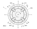
- FIG. 2 is a schematic cross-sectional view orthogonal to the axial direction of the rotor.
- FIG. 1 is a cross-sectional view showing a schematic configuration of a permanent magnet type rotating electric machine according to an embodiment of the present invention. In this figure, only the lower half of the rotor 5 is shown in cross section.
- the rotating electric machine 100 includes a stator 1 and a rotor 5.
- the stator 1 is formed by winding an armature winding around an armature core (both not shown).
- the rotor 5 includes a rotor shaft 9, a sleeve 3 that surrounds the circumferential surface of the rotor shaft 9, and a plurality of field permanent magnets 11 that are disposed between the outer circumferential surface of the rotor shaft 9 and the inner circumferential surface of the sleeve 3. And.
- the rotor 5 is inserted into the shaft center portion of the stator 1, and the rotor shaft 9 is supported by the bearing 7 so that the rotor 5 can rotate with respect to the stator 1.
- a rotating torque is generated by the rotating magnetic field generated in the stator 1 and the field generated in the rotor 5, and the rotor 5 rotates.
- FIG. 2 is a schematic cross-sectional view orthogonal to the axial direction X of the rotor 5.
- a plurality of permanent magnets 11 are arranged in the circumferential direction around the rotor shaft 9 to form an annular row.
- An annular row of a plurality of permanent magnets 11 is arranged in the axial direction X of the rotor 5.
- the inner peripheral surface side (that is, the rotor shaft 9 side) is magnetized to S pole
- the outer peripheral side (that is, the sleeve 3 side) is magnetized to N pole
- the outer peripheral surface side is S pole.
- Those whose inner peripheral surface is magnetized to N poles are alternately arranged according to the number of poles.
- a pair of permanent magnets 11 whose inner peripheral surface is magnetized to the S pole and a pair of permanent magnets 11 whose inner peripheral side is magnetized to the N pole are alternately arranged in the circumferential direction.
- one annular row is formed by a total of eight permanent magnets 11.
- a stopper 4 disposed on the circumference is provided.
- the stopper 4 according to this embodiment is a key 41 driven into the rotor shaft 9.
- the stoppers 4 are provided at four positions with respect to the annular row of one permanent magnet 11, but the stoppers 4 need only be provided at at least one position.
- the key 41 is made of, for example, a non-magnetic material such as a titanium alloy that is lightweight and has a strength that can withstand centrifugal force.
- a plurality of key grooves 92 extending in the axial direction X are provided on the outer peripheral surface of the rotor shaft 9 at predetermined intervals in the circumferential direction.
- the root portion 41 b of the key 41 is fitted into the key groove 92, whereby the key 41 is fixed to the rotor shaft 9. Further, torque can be transmitted from the key 41 thus fixed to the rotor shaft 9.
- the head portion 41a of the key 41 protrudes outward in the radial direction from the key groove 92, and the head portion 41a of the key 41 is located on the same circumference as the permanent magnet 11 forming the annular row.
- the head 41 a of the key 41 substantially functions as the stopper 4.
- each permanent magnet 11 When each permanent magnet 11 is viewed from the axial direction X, each permanent magnet 11 has a sector shape in which the outer arc is slightly larger than the inner arc.
- the key 41 When the key 41 is viewed from the axial direction X, at least the head 41a of the key 41 also has a fan shape.
- the root 41b of the key 41 when the key 41 is viewed from the axial direction X, also has a fan shape, but the shape of the root 41b of the key 41 is not limited to this.
- the plurality of permanent magnets 11 disposed around the rotor shaft 9 and the head 41a of the key 41 have a fan shape, so that they are adjacent to each other. The gaps between the permanent magnets 11 and between the adjacent permanent magnets 11 and the key 41 can be reduced, and the movement of the permanent magnets 11 in the circumferential direction can be more effectively prevented.
- the sleeve 3 of the rotor 5 is composed of a plurality of short sleeves 30 arranged in the axial direction X.
- Each short sleeve 30 is made of, for example, a nonmagnetic material having a strength capable of withstanding a centrifugal force such as a nickel alloy.
- the dimension in the axial direction X of each short sleeve 30 is longer than the dimension in the axial direction X of the permanent magnet 11, and in this embodiment, the dimension in the axial direction X of each short sleeve 30 is the dimension in the axial direction X of the permanent magnet 11. It is about twice.
- the dimensional relationship in the axial direction X between the short sleeve 30 and the permanent magnet 11 is not limited to this embodiment.
- a pair of end members 31 and 32 are provided at both ends in the axial direction X of the plurality of short sleeves 30, that is, at both ends in the axial direction X of the sleeve 3.
- One end member 31 is fixed to the rotor shaft 9.
- the other end member 32 is nut-shaped, and a female screw 321 is formed on the inner periphery thereof.
- a male screw 91 formed on the rotor shaft 9 is screwed into the female screw 321.
- Each short sleeve 30 has a circular opening at both ends in the axial direction X, and a face gear 33 is formed at each opening edge by a plurality of radially extending teeth arranged regularly in the circumferential direction.
- a face gear coupling is formed between the short sleeves 30 adjacent to each other in the axial direction X by meshing the teeth of the face gear 33 provided on each of the opposing surfaces in the axial direction X.
- the plurality of short sleeves 30 arranged in the axial direction X are pressurized from both sides in the axial direction X by the pair of end members 31 and 32, and the adjacent short sleeves 30 are pressed against each other in the axial direction X.
- the short sleeves 30 adjacent to each other in the axial direction X are fixed so as not to move relative to each other in the circumferential direction and the axial direction X, so that they are mechanically butt-joined.
- the adjacent short sleeves 30 mechanically joined in this way can transmit torque.
- a cylindrical (hollow shaft) sleeve 3 is formed by the plurality of short sleeves 30 sequentially connected in the axial direction X in this way.
- the end member 31 is fitted to the rotor shaft 9 from the axial direction X, and the end member 31 is fixed to the rotor shaft 9 by welding or the like.
- the end member 31 has a flange shape protruding from the rotor shaft 9 in the radial direction.
- a face gear 33 is formed on one side of the end member 31 in the axial direction X and on the side where the permanent magnet 11 is disposed.
- the end member 31 may be formed integrally with the rotor shaft 9 by processing the rotor shaft 9.
- each permanent magnet 11 is attached to the outer peripheral surface of the rotor shaft 9 with an adhesive or the like.
- the key 41 is driven into each key groove 92 of the rotor shaft 9.
- the outer peripheral surface of the key 41 and the outer peripheral surface of the permanent magnet 11 may be substantially flush with each other, or the outer peripheral surface of the key 41 is located slightly outward in the radial direction from the outer peripheral surface of the permanent magnet 11. May be.
- a plurality of short sleeves 30 are sequentially fitted from the axial direction X to the rotor shaft 9.
- the short sleeve 30 and the end member 31 fitted first are butted in the axial direction X, and the teeth of the face gear 33 formed on these butting surfaces are meshed.
- the short sleeves 30 arranged in the axial direction X are butted in the axial direction X, and the teeth of the face gear 33 formed on these butting surfaces are meshed.
- the radial gap between the short sleeve 30 and the permanent magnet 11 or the key 41 is filled with a filler made of, for example, a cured resin material.
- the end member 32 is fitted to the rotor shaft 9 from the axial direction X.
- the internal thread of the end member 32 is arranged so that the adjacent short sleeves 30 are pressed against each other in the axial direction X by sandwiching and pressing the sleeve 3 from both sides in the axial direction X by the end member 31 and the end member 32. 321 is screwed into the male screw 91 of the rotor shaft 9.
- the face gear 33 is not formed on the surface that contacts the end member 32.
- the rotor 5 of the rotary electric machine 100 includes the rotor shaft 9, the tubular sleeve 3 that is fitted on the rotor shaft 9 and extends in the axial direction X, and the rotor shaft 9 and the sleeve. 3 and a plurality of field permanent magnets 11 held around the rotor shaft 9 by the sleeve 3.
- the sleeve 3 is composed of a plurality of short sleeves 30 arranged in the axial direction X, and ends of the adjacent short sleeves 30 butted in the axial direction X are mechanically joined so as to transmit torque.
- an eddy current is generated in the permanent magnet 11, and similarly, an eddy current is also generated in the sleeve 3.
- the sleeve 3 is configured to be subdivided in the axial direction X, the electricity of the sleeve 3 can be compared with the case where the sleeve 3 is a single body or the case where the short sleeves 30 are joined together by welding. The resistance is large, and the eddy current path (the length of eddy current flow) is shortened.
- the eddy current flowing through the sleeve 3 decreases as a whole, and the energy loss of the rotating electrical machine 100 can be suppressed by reducing the eddy current loss. Furthermore, since heat generation due to eddy current can be suppressed, the risk of permanent demagnetization of the permanent magnet 11 due to the temperature rise of the sleeve 3 can be reduced.
- the sleeve 3 is subdivided in the axial direction X, when the axial direction X length of the rotor 5 is longer than the radius, the sleeve 3 is integrated. Compared with the case where it is, processing becomes easy. As a result, the shape accuracy of the sleeve 3 can be increased. Furthermore, since the short sleeves 30 are mechanically joined rather than welded, in order to weld the short sleeves 30 to each other, the welded portion is avoided so that the welding heat does not reach the permanent magnet 11. Therefore, it is not necessary to arrange or precisely position the short sleeve 30 and the permanent magnet 11 for that purpose. Therefore, the large rotor 5 in which the output density of the rotating electric machine 100 is improved can be easily realized.
- the end portions of the adjacent short sleeves 30 butted in the axial direction X are mechanically joined by face gear coupling.
- the face gear coupling includes a Kirbic coupling, a hearth coupling, and the like, but any mode may be used as long as the face gear 33 formed on the abutting surface meshes.
- the short sleeve 30 can be connected in the circumferential direction and positioned in the circumferential direction simply by meshing the face gears 33 of the short sleeve 30. And self-aligning. Thereby, the operation
- a face gear coupling as a mechanical joining method between the short sleeves 30, but the mechanical joining method is not limited to this.
- Any mechanical joining method may be used for the short sleeves 30 as long as they can be butt-joined to transmit torque.
- a mechanical joining method for example, an internal gear is formed on one short sleeve 30, an external gear is formed on the other short sleeve 30, and gear couplings in which the teeth of these gears are engaged,
- An example is a gear coupling in which an external gear is formed at the abutting ends of both the short sleeves 30 and the short sleeve 30 is connected with a collar having an internal gear that meshes with these external gears.
- the rotor 5 of this embodiment includes a pair of end members 31 and 32 fixed to the rotor shaft 9.
- the pair of end members 31 and 32 sandwich the sleeve 3 from both sides in the axial direction X and press the adjacent short sleeves 30 together.
- the short sleeve 30 initially fitted to the rotor shaft 9 and the end member 31 fixed to the rotor shaft 9 are mechanically joined so as to transmit torque.
- the combination of the short sleeve 30 and the end member 31 is not limited to the above, and one of the plurality of short sleeves 30 and one of the pair of end members 31 and 32 fixed to the rotor shaft 9 are: It only needs to be mechanically joined so that torque can be transmitted.
- a face gear coupling is adopted as a mechanical joining method between the end member 31 and the short sleeve 30, but the mechanical joining method is not limited to this.
- the permanent magnet 11 In general, in the surface magnet type rotary electric machine 100, when the rotation of the rotor 5 becomes high speed, the permanent magnet 11 is released from the surface of the rotor shaft 9 due to the centrifugal force acting on the permanent magnet 11, and moves outward in the radial direction. Try to jump out. On the other hand, in the rotor 5 of this embodiment, the permanent magnet 11 is prevented from moving outward in the radial direction by the sleeve 3 positioned radially outward, and the permanent magnet 11 is held on the outer peripheral surface of the rotor shaft 9. .
- the permanent magnet 11 released from the surface of the rotor shaft 9 is pressed against the sleeve 3, and the permanent magnet 11 and the sleeve 3 rotate together by friction between the permanent magnet 11 and the inner peripheral surface of the sleeve 3.
- the torque of the permanent magnet 11 (magnet torque) generated by the magnetic field of the permanent magnet 11 of the rotor 5 and the pole of the rotating magnetic field is transmitted via the sleeve 3. Is transmitted to the rotor shaft 9.
- the torque of the permanent magnet 11 can be reliably transmitted to the rotor shaft 9. Therefore, even if the rotation of the rotor 5 is increased, the predetermined performance of the rotating electric machine 100 can be obtained.
- a part of the plurality of permanent magnets 11 are arranged on the same circumference on the outer circumferential surface of the rotor shaft 9 to form an annular row, and in the circumferential direction of the annular row A stopper 4 is provided between the adjacent permanent magnets 11.
- the stopper 4 is disposed on the same circumference as the permanent magnet 11 forming an annular row, and is fixed to the rotor shaft 9 so as to be able to transmit torque.
- the permanent magnet 11 released from the surface of the rotor shaft 9 by the centrifugal force during the rotation of the rotor 5 generates a shearing force due to torque between the permanent magnet 11 and the rotor shaft 9, and the permanent magnet 11 is moved to the rotor shaft. 9 tries to move in the circumferential direction on the outer peripheral surface.
- the stopper 4 the head 41a of the key 41
- the stopper 4 prevents the permanent magnet 11 from moving in the circumferential direction with respect to the rotor shaft 9. 11 circumferential positions are maintained. Thereby, the favorable rotation balance of the rotor 5 is maintained, and the electrical control of the rotary electric machine 100 is stably maintained.
- the permanent magnet 11 released from the surface of the rotor shaft 9 is pressed against the stopper 4 while the permanent magnet 11 released from the surface of the rotor shaft 9 is pressed against the rotor via the stopper 4. It is transmitted to the shaft 9.
- the torque of the permanent magnet 11 can be reliably transmitted to the rotor shaft 9. Therefore, even if the rotation of the rotor 5 is increased, the predetermined performance of the rotating electric machine 100 can be obtained.
- the stopper 4 includes a root portion 41 b fitted in a key groove 92 formed in the rotor shaft 9 and a head portion 41 a that protrudes in the radial direction from the outer peripheral surface of the rotor shaft 9.
- the key 41 is realized.
- the stopper 4 joined to the rotor shaft 9 so as to be able to transmit torque can have a simple and easily manufactured structure.
- the stopper 4 according to the present invention is not limited to the key 41 and may be a member that is fixed so as to be able to transmit torque to the rotor shaft 9 and that can prevent the permanent magnet 11 from moving in the circumferential direction. That's fine.
- each of the short sleeve 30 and the stopper 4 is made of a nonmagnetic material.
- the influence which the sleeve 3 and the stopper 4 exert on the electromagnetic design of the rotor 5 can be suppressed.
- a material having a small electrical resistance is selected as the material of the short sleeve 30, heat generation due to eddy current can be more effectively suppressed.
- Stator 3 Sleeve 4: Stopper 41: Key 41a: Head 41b: Root part 5: Rotor 9: Rotor shaft 11: Permanent magnet 30: Short sleeve 31: End member 32: End member 33: Face gear 92: Key groove 100: Rotating electric machine
Landscapes
- Engineering & Computer Science (AREA)
- Power Engineering (AREA)
- Permanent Field Magnets Of Synchronous Machinery (AREA)
- Iron Core Of Rotating Electric Machines (AREA)
Abstract
回転電気機械のロータが、ロータ軸と、ロータ軸に外嵌された軸方向Xに延びる筒状のスリーブと、ロータ軸とスリーブとの半径方向の間に設けられ、スリーブによってロータ軸の周囲に保持された界磁用の複数の永久磁石とを備えている。スリーブは、軸方向Xに並ぶ複数のショートスリーブから成り、隣接するショートスリーブの軸方向Xに突き合わされた端部同士がトルク伝達可能に機械的に接合されている。
Description
本発明は、永久磁石形同期回転電気機械のロータの構造に関する。
従来、永久磁石形同期モータや永久磁石形同期発電機などの、界磁に永久磁石を用いた永久磁石形同期回転電気機械が知られている。永久磁石形同期回転電気機械は、ロータへの永久磁石保持態様の違いから、磁石がロータ表面に組み込まれた表面磁石形(SPM:Surface Permanent Magnet)と、磁石がロータの鉄心内部に組み込まれた埋込磁石形(IPM:Interior permanent Magnet)とに大きく分類される。特許文献1には、そのうち表面磁石形の回転電気機械が示されている。
特許文献1に記載の永久磁石形回転電気機械は、電機子鉄心に電機子巻線が巻回されて成るステータと、ステータの軸心部に回転可能に内挿されたロータとを備えている。このロータは、シャフトと、シャフトの軸方向に並んで当該シャフトの周面を覆う複数の保持環と、複数の保持環の内周面に固着された界磁用の複数の永久磁石とを備えている。軸方向に並ぶ複数の保持環は互いに溶接接合されている。この回転電気機械では、ロータが回転しているときに永久磁石に作用する遠心力によって当該永久磁石が飛び出さないように、複数の保持環によって永久磁石がロータの周囲に保持される。
本発明は、上記のような表面磁石形の永久磁石形同期回転電気機械のロータにおいて、回転電気機械のロータの回転を高速化しても所定の性能を発揮し得る永久磁石の保持構造を提供することを目的とする。
近年では、永久磁石の高性能化と低価格化に伴い、大型の回転電気機械にも永久磁石が使われるようになった。このような大型の回転電気機械では、永久磁石が大きくなり、更に、ロータの回転が高速化されることにより、永久磁石からの渦電流によるエネルギー損失も大きくなる。特許文献1の回転電気機械では、永久磁石を保持する複数の保持環は導体であり、ここにも渦電流が流れて渦電流損が発生する。特許文献1の複数の保持環は溶接により一体化されていることから電気抵抗が小さく、保持環に生じる渦電流によるエネルギー損失を抑えることができない。
そこで、本発明の第一の態様に係る回転電気機械のロータは、
ロータ軸と、
前記ロータ軸に外嵌された軸方向に延びる筒状のスリーブと、
前記ロータ軸と前記スリーブとの半径方向の間に設けられ、前記スリーブによって前記ロータ軸の周囲に保持された界磁用の複数の永久磁石とを備え、
前記スリーブが前記軸方向に並ぶ複数のショートスリーブから成り、隣接するショートスリーブの前記軸方向に突き合わされた端部同士がトルク伝達可能に機械的に接合されていることを特徴としている。
ロータ軸と、
前記ロータ軸に外嵌された軸方向に延びる筒状のスリーブと、
前記ロータ軸と前記スリーブとの半径方向の間に設けられ、前記スリーブによって前記ロータ軸の周囲に保持された界磁用の複数の永久磁石とを備え、
前記スリーブが前記軸方向に並ぶ複数のショートスリーブから成り、隣接するショートスリーブの前記軸方向に突き合わされた端部同士がトルク伝達可能に機械的に接合されていることを特徴としている。
上記ロータでは、スリーブが軸方向に細分化されており、且つ、ショートスリーブ同士が機械的に接合されていることから、スリーブが一体物である場合やショートスリーブ同士が溶接で接合されている場合と比較して、スリーブの電気抵抗が大きく、渦電流の電流路が短くなる。その結果、スリーブを流れる渦電流が減少し、渦電流損を低減することができる。よって、ロータの回転が高速化しても、回転電気機械は所定の性能を発揮することができる。
また、ショートスリーブ同士がトルク伝達可能に接合されているので、スリーブを利用して回転トルクを伝達することが可能である。
更に、スリーブが軸方向に細分化されているので、スリーブが一体物である場合と比較して加工が容易となる。その結果、スリーブの形状精度を高めることができ、回転電気機械の出力密度を向上させた大型のロータを容易に実現することができる。
上記回転電気機械のロータにおいて、前記隣接するショートスリーブの前記軸方向に突き合わされた端部同士がフェースギアカップリングにより接合されていてよい。
これにより、ショートスリーブのフェースギア同士を噛み合わせるだけでショートスリーブ同士の円周方向の連結、円周方向の位置決め、及び自動調心が為されるので、ロータの製造作業を簡易化することができる。
上記回転電気機械のロータは、前記スリーブを前記軸方向の両側から挟み込んで、前記隣接するショートスリーブ同士を圧接させる、前記ロータ軸に固定された一対のエンド部材を更に備えていてよい。
このように一対のエンド部材で複数のショートスリーブを挟み込むことによって、複数のショートスリーブを一体化することができる。
上記回転電気機械のロータにおいて、前記複数のショートスリーブのうちの一つと、前記ロータ軸に固定された一対のエンド部材のうちの一つとが、トルク伝達可能に機械的に接合されている。
これにより、ロータの回転時にロータ軸から遊離した永久磁石がスリーブに押し付けられるので、この永久磁石のトルクがスリーブを介してロータ軸へ伝達される。
上記回転電気機械のロータにおいて、前記複数のショートスリーブが非磁性材料で構成されていてよい。
これにより、スリーブによってロータの電磁気設計に与える影響を抑えることができる。
ところで、表面磁石形の回転電気機械では、ロータの回転数の増加に伴い磁石に作用する遠心力が増大して、遠心力がロータ軸の外周面から遊離する。そうなると、磁石がスリーブに十分に押し付けられなければ、磁石のトルクをロータ軸に効率的に伝達することができなくなって所定の性能が得られなくなったり、ロータのバランスが崩れて振動が生じたりする。
そこで、本発明の第二の態様に係る回転電気機械のロータは、
ロータ軸と、
前記ロータ軸に外嵌された軸方向に延びる筒状のスリーブと、
前記ロータ軸と前記スリーブとの半径方向の間に設けられ、前記スリーブによって前記ロータ軸の周囲に保持された界磁用の複数の永久磁石と、
前記複数の永久磁石の一部が、前記ロータ軸の外周面において同一円周上に並んで環状列を形成しており、前記環状列の円周方向に隣接している永久磁石の間においてこれらの永久磁石と同一円周上に配置され、前記ロータ軸にトルク伝達可能に固定されたストッパとを備えることを特徴としている。
ロータ軸と、
前記ロータ軸に外嵌された軸方向に延びる筒状のスリーブと、
前記ロータ軸と前記スリーブとの半径方向の間に設けられ、前記スリーブによって前記ロータ軸の周囲に保持された界磁用の複数の永久磁石と、
前記複数の永久磁石の一部が、前記ロータ軸の外周面において同一円周上に並んで環状列を形成しており、前記環状列の円周方向に隣接している永久磁石の間においてこれらの永久磁石と同一円周上に配置され、前記ロータ軸にトルク伝達可能に固定されたストッパとを備えることを特徴としている。
また、上記第一の態様に係る回転電気機械のロータにおいて、前記複数の永久磁石の一部が、前記ロータ軸の外周面において同一円周上に並んで環状列を形成しており、前記ロータが、前記環状列の円周方向に隣接している永久磁石の間においてこれらの永久磁石と同一円周上に配置され、前記ロータ軸にトルク伝達可能に固定されたストッパを更に備えていてもよい。
上記のようにロータに備えられたストッパにより、ロータの回転時にロータ軸から遊離した永久磁石の円周方向への移動が阻止されるので、ロータ軸に対する永久磁石の円周方向位置が保持される。また、ロータの回転時にロータ軸から遊離した永久磁石がストッパに押し付けられるので、この永久磁石のトルクがストッパを介してロータ軸へ伝達される。このように、永久磁石がロータ軸から遊離しても永久磁石のトルクをロータ軸へ伝達することができるので、ロータの回転が高速化しても、回転電気機械は所定の性能を発揮することができる。また、ロータのバランスが崩れることに起因する振動を抑えることができる。
上記第一及び第二の態様に係る回転電気機械のロータにおいて、前記ストッパが非磁性材料で構成されていてよい。
これにより、ストッパによってロータの電磁気設計に与える影響を抑えることができる。
上記第一及び第二の態様に係る回転電気機械のロータにおいて、前記ストッパが、前記ロータ軸に形成されたキー溝に嵌め込まれた基部と、前記ロータ軸の外周面から半径方向に突出する頭部とを有するキーであってよい。
これにより、ロータ軸にトルク伝達可能に接合されたストッパを単純且つ製造容易な構造で実現することができる。
本発明によれば、表面磁石形の永久磁石形同期回転電気機械のロータにおいて、ロータの回転を高速化しても、回転電気機械が所定の性能を発揮することのできる、永久磁石の保持構造を提供することができる。
次に、図面を参照して本発明の実施の形態を説明する。先ず、図1を参照しながら、本発明の一実施形態に係る回転電気機械100の概略構成から説明する。図1は本発明の一実施形態に係る永久磁石形回転電気機械の概略構成を示す断面図である。この図において、ロータ5は下半分のみが断面で示されている。
回転電気機械100は、ステータ1とロータ5とを備えている。ステータ1は、電機子鉄心に電機子巻線が巻回されて成る(いずれも図示略)。ロータ5は、ロータ軸9と、ロータ軸9の周面を取り囲むスリーブ3と、ロータ軸9の外周面とスリーブ3の内周面との間に配置された複数の界磁用の永久磁石11とを備えている。ロータ5はステータ1の軸心部に挿入され、ステータ1に対しロータ5が回転自在となるようにロータ軸9が軸受7に支持されている。上記構成の回転電気機械100では、ステータ1に生じた回転磁界とロータ5に生じた界磁とにより回転トルクが発生し、ロータ5が回転する。
次に、ロータ5の構造について詳細に説明する。図2はロータ5の軸方向Xと直交する概略断面図である。
図1及び図2に示すように、ロータ軸9の周囲には、複数の永久磁石11が円周方向に並べられて環状列を成している。そして、複数の永久磁石11の環状列がロータ5の軸方向Xに並べられている。
永久磁石11の環状列には、内周面側(即ち、ロータ軸9側)がS極、外周側(即ち、スリーブ3側)がN極に磁化されたものと、外周面側がS極、内周面側がN極に磁化されたものとが、極数に応じて交互に配置されている。本実施形態においては、内周面側がS極に磁化された1ペアの永久磁石11と、内周側がN極に磁化された1ペアの永久磁石11とが交互に円周方向に並べられており、合計8個の永久磁石11によって1つの環状列が形成されている。
内周面側がS極に磁化された1ペアの永久磁石11と、内周側がN極に磁化された1ペアの永久磁石11との円周方向の間に、これらの永久磁石11と同一円周上に配置されたストッパ4が設けられている。本実施形態に係るストッパ4は、ロータ軸9に打ち込まれたキー41である。本実施形態において、1の永久磁石11の環状列に対し、4箇所においてストッパ4が設けられているが、ストッパ4は少なくとも1箇所に設けられていればよい。
キー41は、例えば、軽量で且つ遠心力に耐えうる強度を有するチタン合金などの非磁性体材料で構成されている。ロータ軸9の外周面には、軸方向Xに延びる複数のキー溝92が、円周方向に所定間隔で設けられている。キー41の根部41bはキー溝92に嵌め込まれ、これにより、キー41がロータ軸9に固定されている。また、このように固定されたキー41からロータ軸9へトルクの伝達が可能である。キー41の頭部41aはキー溝92より半径方向外向きに突出しており、このキー41の頭部41aは環状列を形成している永久磁石11と同一円周上に位置している。キー41のうち頭部41aが実質的にストッパ4として機能する。
各永久磁石11を軸方向Xから見たときに、各永久磁石11は内周側円弧と比べて外周側円弧が若干大きい扇形形状を有している。そして、キー41を軸方向Xから見たときに、キー41の少なくとも頭部41aも扇形形状を有している。本実施形態では、キー41を軸方向Xから見たときに、キー41の根部41bも扇形形状を有するが、キー41の根部41bの形状はこれに限定されない。上記のように、ロータ5を軸方向Xから見たときに、ロータ軸9の周囲に配置される複数の永久磁石11及びキー41の頭部41aが扇形形状を有しているので、隣接する永久磁石11間、及び、隣接する永久磁石11とキー41との間の間隙を詰めることができ、永久磁石11の円周方向への移動をより効果的に阻止することができる。
ロータ5のスリーブ3は、軸方向Xに並ぶ複数のショートスリーブ30から構成されている。各ショートスリーブ30は、例えば、ニッケル合金などの遠心力に耐えうる強度を有する非磁性材料で構成されている。各ショートスリーブ30の軸方向Xの寸法は、永久磁石11の軸方向Xの寸法より長く、本実施形態においては、各ショートスリーブ30の軸方向Xの寸法は永久磁石11の軸方向Xの寸法のおよそ2倍となっている。但し、ショートスリーブ30と永久磁石11の軸方向Xの寸法関係は本実施形態に限定されない。
複数のショートスリーブ30の軸方向Xの両端、即ち、スリーブ3の軸方向Xの両端には、一対のエンド部材31,32が設けられている。一方のエンド部材31はロータ軸9に固定されている。他方のエンド部材32はナット状であって、その内周に雌ネジ321が形成されている。この雌ネジ321には、ロータ軸9に形成された雄ネジ91が螺入されている。
各ショートスリーブ30は軸方向Xの両端部に円形の開口を有し、各開口縁には円周方向に規則的に並んだ複数の放射状に延びる歯によってフェースギア33が形成されている。軸方向Xに隣接するショートスリーブ30間では、軸方向Xの対向面の各々に設けられたフェースギア33の歯が噛み合うことにより、フェースギアカップリングが形成されている。このフェースギアカップリングにより、隣接するショートスリーブ30の円周方向の連結、円周方向の位置決め、及び自動調心が為されている。
軸方向Xに並ぶ複数のショートスリーブ30は、一対のエンド部材31,32によって軸方向X両側から加圧され、隣接するショートスリーブ30同士が軸方向Xに圧接されている。このようにして軸方向Xに隣接するショートスリーブ30同士が、円周方向と軸方向Xに相対的移動不能に固定されることによって、機械的に突き合わせ接合されている。このように機械的に接合された隣接するショートスリーブ30同士はトルクを伝達可能である。そして、このように軸方向Xに順次接続された複数のショートスリーブ30によって筒状(中空軸状)のスリーブ3が形成されている。
続いて、上記構成のロータ5の製造方法について説明する。
まず、ロータ軸9にエンド部材31を軸方向Xから嵌めて、エンド部材31をロータ軸9に溶接などによって固定する。エンド部材31はロータ軸9から半径方向に出っ張ったフランジ形状を成している。エンド部材31の軸方向Xの一方側であって永久磁石11が配置される側には、フェースギア33が形成されている。なお、エンド部材31は、ロータ軸9の加工により当該ロータ軸9と一体的に成形されたものであってもよい。
次に、ロータ軸9の周囲に複数の永久磁石11を配置し、各永久磁石11を接着剤等によってロータ軸9の外周面に貼りつける。続いて、ロータ軸9の各キー溝92にキー41が打ち込む。ここで、キー41の外周面と永久磁石11の外周面とが概ね面一となっていてもよいし、キー41の外周面が永久磁石11の外周面よりも若干半径方向外側へ位置していてもよい。
続いて、ロータ軸9に複数のショートスリーブ30を順に軸方向Xから嵌める。ここで、最初に嵌められたショートスリーブ30とエンド部材31とを軸方向Xに突き合わせて、これらの突き合わせ面に形成されたフェースギア33の歯を噛み合わせる。また、軸方向Xに並ぶショートスリーブ30を軸方向Xに突き合わせて、これらの突き合わせ面に形成されたフェースギア33の歯を噛み合わせる。ロータ軸9にショートスリーブ30を嵌める前又は後で、ショートスリーブ30と永久磁石11又はキー41との半径方向の間隙を例えば硬化樹脂材料製の充填材で埋める。
最後に、ロータ軸9にエンド部材32を軸方向Xから嵌める。ここで、エンド部材31及びエンド部材32によってスリーブ3を軸方向Xの両側から挟み込んで加圧することによって、隣接するショートスリーブ30同士が軸方向Xに圧接されるように、エンド部材32の雌ネジ321をロータ軸9の雄ネジ91にねじ込む。なお、ロータ軸9に最後に嵌められたショートスリーブ30において、エンド部材32と接触する面にはフェースギア33は形成されていない。以上の工程により、ロータ5を製造することができる。
以上に説明したように、本実施形態の回転電気機械100のロータ5は、ロータ軸9と、ロータ軸9に外嵌された軸方向Xに延びる筒状のスリーブ3と、ロータ軸9とスリーブ3との半径方向の間に設けられ、スリーブ3によってロータ軸9の周囲に保持された界磁用の複数の永久磁石11とを備えている。そして、スリーブ3は、軸方向Xに並ぶ複数のショートスリーブ30から成り、隣接するショートスリーブ30の軸方向Xに突き合わされた端部同士がトルク伝達可能に機械的に接合されている。
回転電気機械100のロータ5が回転すると、永久磁石11に渦電流が生じ、同様に、スリーブ3にも渦電流が生じる。ここで、スリーブ3が軸方向Xに細分化された構成となっているので、スリーブ3が一体物である場合やショートスリーブ30同士が溶接で接合されている場合と比較してスリーブ3の電気抵抗が大きく、渦電流の電流路(渦電流の流れる長さ)が短くなる。その結果、スリーブ3を流れる渦電流が全体として減少し、渦電流損の低減により、回転電気機械100のエネルギー損失を抑えることができる。更に、渦電流による発熱も抑制できるので、スリーブ3の温度上昇による永久磁石11の永久減磁のリスクを軽減することができる。
上記ロータ5では、ショートスリーブ30同士がトルク伝達可能に接合されているので、スリーブ3を利用して回転トルクを伝達することが可能となる。
上記ロータ5では、スリーブ3が軸方向Xに細分化された構成となっているので、ロータ5の軸方向X長さが半径と比較して長尺となる場合には、スリーブ3が一体物である場合と比較して加工が容易となる。その結果、スリーブ3の形状精度を高めることができる。更に、ショートスリーブ30同士は溶接ではなく機械的に接合されていることから、ショートスリーブ30同士を溶接するためにその溶接熱が永久磁石11に及ばないように溶接部を避けて永久磁石11を配置したり、そのためにショートスリーブ30と永久磁石11とを精確に位置決めしたりすることが不要である。よって、回転電気機械100の出力密度を向上させた大型のロータ5を容易に実現することができる。
また、本実施形態のロータ5において、隣接するショートスリーブ30の軸方向Xに突き合わされた端部同士の機械的接合はフェースギアカップリングによりなされている。なお、フェースギアカップリングには、カービックカップリングやハースカップリングなどがあるが、突き合わせ面に形成されたフェースギア33が噛み合う態様であればいずれでもよい。
このようにショートスリーブ30同士の機械的接合方式としてフェースギアカップリングを用いることで、ショートスリーブ30のフェースギア33同士を噛み合わせるだけでショートスリーブ30の円周方向の連結、円周方向の位置決め、及び自動調心が為される。これにより、ロータ5の製造においてスリーブ3を形成する作業を簡易化することができる。更に、フェースギアカップリングによって結合された複数のショートスリーブ30は一体的な中空軸と等しい状態となるので、ボルトなどの他の接手に比較して高トルクの伝達が可能であり、また、ロータ5の高速回転中もショートスリーブ30同士の相対的位置を良好に固定することができる。
上記のようにショートスリーブ30同士の機械的接合方式としてフェースギアカップリングを用いることが望ましいが、機械的接合方式はこれに限定されない。ショートスリーブ30同士の機械的接合方式は、トルク伝達可能に両者を突き合わせ接合できるものであればよい。このような機械的接合方式として、例えば、一方のショートスリーブ30にインターナルギアを形成し、他方のショートスリーブ30にエクスターナルギアを形成して、これらのギアの歯を噛み合わせたギアカップリングや、双方のショートスリーブ30の突き合わせ端部にエクスターナルギアを形成し、これらのエクスターナルギアと噛み合うインターネルギアを有するカラーでショートスリーブ30を繋ぎ合わせるギアカップリングなどを挙げることができる。
また、本実施形態のロータ5は、ロータ軸9に固定された一対のエンド部材31,32を備えている。これら一対のエンド部材31,32は、スリーブ3を軸方向Xの両側から挟み込んで、隣接するショートスリーブ30同士を圧接させている。
このように一対のエンド部材31,32によってスリーブ3が軸方向X両側から挟み込まれることによって、隣接するショートスリーブ30同士が軸方向Xに圧接され、複数のショートスリーブ30が一体化される。このような構造によれば、ロータ5の製造において、隣接するショートスリーブ30を個々に圧接する作業を行わなくて済むので、ロータ5の製造作業を簡易化することができる。
また、本実施形態のロータ5において、ロータ軸9に最初に嵌められたショートスリーブ30と、ロータ軸9に固定されたエンド部材31とがトルク伝達可能に機械的に接合されている。但し、ショートスリーブ30とエンド部材31の組み合わせは上記に限定されず、複数のショートスリーブ30のうちの一つと、ロータ軸9に固定された一対のエンド部材31,32のうちの一つとが、トルク伝達可能に機械的に接合されていればよい。ここでは、エンド部材31とショートスリーブ30との機械的接合方式としてフェースギアカップリングが採用されているが、機械的接合方式はこれに限定されない。
一般に、表面磁石形の回転電気機械100では、ロータ5の回転が高速となると、永久磁石11に作用する遠心力によって永久磁石11がロータ軸9の表面から遊離し(浮き上がり)、半径方向外側へ飛び出そうとする。これに対し、本実施形態のロータ5では、永久磁石11はその半径方向外側に位置するスリーブ3によって半径方向外向きの移動が阻止され、永久磁石11はロータ軸9の外周面に保持される。このとき、ロータ軸9の表面から遊離した永久磁石11は、スリーブ3に押し付けられており、永久磁石11とスリーブ3内周面との摩擦により永久磁石11とスリーブ3とが一体となって回転する。ここで、スリーブ3とロータ軸9とがトルク伝達可能に接合されているので、ロータ5の永久磁石11の磁界と回転磁界の極によって生じる永久磁石11のトルク(マグネットトルク)はスリーブ3を介してロータ軸9へ伝達される。このように、永久磁石11がロータ軸9から遊離しても、永久磁石11のトルクを確実にロータ軸9へ伝達することができる。よって、ロータ5の回転を高速化しても、回転電気機械100の所定の性能を得ることができる。
また、本実施形態のロータ5において、複数の永久磁石11の一部が、ロータ軸9の外周面において同一円周上に並んで環状列を形成しており、この環状列の円周方向に隣接している永久磁石11の間にストッパ4が設けられている。ストッパ4は、環状列を成す永久磁石11と同一円周上に配置されており、ロータ軸9にトルク伝達可能に固定されている。
前述の通りロータ5の回転時に遠心力によってロータ軸9の表面から遊離した永久磁石11は、永久磁石11とロータ軸9との間にトルクに起因する剪断力が生じ、永久磁石11がロータ軸9の外周面上を円周方向へ移動しようとする。これに対し、本実施形態に係るロータ5では、ストッパ4(キー41の頭部41a)によって永久磁石11のロータ軸9に対する円周方向への移動が阻止されるので、ロータ軸9に対する永久磁石11の円周方向位置が保持される。これにより、ロータ5の良好な回転バランスが維持され、回転電気機械100の電気的な制御が安定的に維持される。
そして、上記のようにロータ軸9の表面から遊離した永久磁石11はロータ軸9の表面から遊離した永久磁石11はストッパ4に押し付けられており、永久磁石11のトルクはストッパ4を介してロータ軸9へ伝達される。このように、永久磁石11がロータ軸9から遊離しても、永久磁石11のトルクを確実にロータ軸9へ伝達することができる。よって、ロータ5の回転を高速化しても、回転電気機械100の所定の性能を得ることができる。
また、本実施形態のロータ5では、上記ストッパ4が、ロータ軸9に形成されたキー溝92に嵌め込まれた根部41bと、ロータ軸9の外周面から半径方向に突出する頭部41aとを有するキー41として実現されている。
このようにして、ロータ軸9にトルク伝達可能に接合されたストッパ4を単純且つ製造容易な構造とすることができる。但し、本発明に係るストッパ4はキー41に限定されず、ロータ軸9に対しトルク伝達可能に固定されており、且つ、永久磁石11の円周方向の移動を阻止することができる部材であればよい。
また、本実施形態のロータ5において、各ショートスリーブ30及びストッパ4は、いずれも非磁性材料で構成されている。これにより、スリーブ3やストッパ4によってロータ5の電磁気設計に与える影響を抑えることができる。特に、ショートスリーブ30の材料として、電気抵抗が小さいものを選ぶと、渦電流による発熱をより効果的に抑制することができる。
以上に本発明の好適な実施形態を説明した。この説明から、当業者にとっては、本発明の多くの改良や他の実施形態が明らかである。従って、上記説明は、例示としてのみ解釈されるべきであり、本発明を実行する最良の態様を当業者に教示する目的で提供されたものである。本発明の精神を逸脱することなく、その構造及び/又は機能の詳細を実質的に変更できる。
1 :ステータ
3 :スリーブ
4 :ストッパ
41 :キー
41a:頭部
41b:根部
5 :ロータ
9 :ロータ軸
11 :永久磁石
30 :ショートスリーブ
31 :エンド部材
32 :エンド部材
33 :フェースギア
92 :キー溝
100 :回転電気機械
3 :スリーブ
4 :ストッパ
41 :キー
41a:頭部
41b:根部
5 :ロータ
9 :ロータ軸
11 :永久磁石
30 :ショートスリーブ
31 :エンド部材
32 :エンド部材
33 :フェースギア
92 :キー溝
100 :回転電気機械
Claims (9)
- ロータ軸と、
前記ロータ軸に外嵌された軸方向に延びる筒状のスリーブと、
前記ロータ軸と前記スリーブとの半径方向の間に設けられ、前記スリーブによって前記ロータ軸の周囲に保持された界磁用の複数の永久磁石とを備え、
前記スリーブが前記軸方向に並ぶ複数のショートスリーブから成り、隣接するショートスリーブの前記軸方向に突き合わされた端部同士がトルク伝達可能に機械的に接合されている、
回転電気機械のロータ。 - 前記隣接するショートスリーブの前記軸方向に突き合わされた端部同士がフェースギアカップリングにより接合されている、
請求項1に記載の回転電気機械のロータ。 - 前記スリーブを前記軸方向の両側から挟み込んで、前記隣接するショートスリーブ同士を圧接させる、前記ロータ軸に固定された一対のエンド部材を更に備える、
請求項1又は2に記載の回転電気機械のロータ。 - 前記複数のショートスリーブのうちの一つと、前記ロータ軸に固定された一対のエンド部材のうちの一つとが、トルク伝達可能に機械的に接合されている、
請求項3に記載の回転電気機械のロータ。 - 前記複数のショートスリーブが非磁性材料で構成されている、
請求項1~4のいずれか一項に記載の回転電気機械のロータ。 - 前記複数の永久磁石の一部が、前記ロータ軸の外周面において同一円周上に並んで環状列を形成しており、
前記環状列の円周方向に隣接している永久磁石の間においてこれらの永久磁石と同一円周上に配置され、前記ロータ軸にトルク伝達可能に固定されたストッパを更に備える、
請求項1~5のいずれか一項に記載の回転電気機械のロータ。 - ロータ軸と、
前記ロータ軸に外嵌された軸方向に延びる筒状のスリーブと、
前記ロータ軸と前記スリーブとの半径方向の間に設けられ、前記スリーブによって前記ロータ軸の周囲に保持された界磁用の複数の永久磁石と、
前記複数の永久磁石の一部が、前記ロータ軸の外周面において同一円周上に並んで環状列を形成しており、前記環状列の円周方向に隣接している永久磁石の間においてこれらの永久磁石と同一円周上に配置され、前記ロータ軸にトルク伝達可能に固定されたストッパとを備える、
回転電気機械のロータ。 - 前記ストッパが非磁性材料で構成されている、
請求項6又は7に記載の回転電気機械のロータ。 - 前記ストッパが、前記ロータ軸に形成されたキー溝に嵌め込まれた基部と、前記ロータ軸の外周面から半径方向に突出する頭部とを有するキーである、
請求項6~8のいずれか一項に記載の回転電気機械のロータ。
Priority Applications (2)
| Application Number | Priority Date | Filing Date | Title |
|---|---|---|---|
| DE112016004399.6T DE112016004399T5 (de) | 2015-10-28 | 2016-10-20 | Rotor für eine elektrische drehmaschine |
| US15/772,103 US10978924B2 (en) | 2015-10-28 | 2016-10-20 | Rotor of electrical rotating machine |
Applications Claiming Priority (2)
| Application Number | Priority Date | Filing Date | Title |
|---|---|---|---|
| JP2015-211743 | 2015-10-28 | ||
| JP2015211743A JP6618768B2 (ja) | 2015-10-28 | 2015-10-28 | 回転電気機械のロータ |
Publications (1)
| Publication Number | Publication Date |
|---|---|
| WO2017073036A1 true WO2017073036A1 (ja) | 2017-05-04 |
Family
ID=58630173
Family Applications (1)
| Application Number | Title | Priority Date | Filing Date |
|---|---|---|---|
| PCT/JP2016/004639 Ceased WO2017073036A1 (ja) | 2015-10-28 | 2016-10-20 | 回転電気機械のロータ |
Country Status (4)
| Country | Link |
|---|---|
| US (1) | US10978924B2 (ja) |
| JP (1) | JP6618768B2 (ja) |
| DE (1) | DE112016004399T5 (ja) |
| WO (1) | WO2017073036A1 (ja) |
Cited By (1)
| Publication number | Priority date | Publication date | Assignee | Title |
|---|---|---|---|---|
| CN109245361A (zh) * | 2018-10-08 | 2019-01-18 | 珠海格力电器股份有限公司 | 电机转子、电机和空调器 |
Families Citing this family (10)
| Publication number | Priority date | Publication date | Assignee | Title |
|---|---|---|---|---|
| CN109302044B (zh) * | 2018-12-11 | 2023-12-22 | 开天传动技术(上海)有限公司 | 一种可调双离合机构的永磁联轴器 |
| CN110224642B (zh) * | 2019-04-25 | 2020-12-22 | 上海电机系统节能工程技术研究中心有限公司 | 一种同步电机的设计方法 |
| EP3758195A1 (en) * | 2019-06-27 | 2020-12-30 | General Electric Company | Permanent magnet machine |
| KR102951770B1 (ko) * | 2019-12-23 | 2026-04-14 | 엘지이노텍 주식회사 | 모터 |
| EP4131742A4 (en) * | 2020-03-25 | 2024-04-10 | IHI Corporation | ROTOR OF AN ELECTRIC LATHE |
| CN113098220A (zh) * | 2021-03-14 | 2021-07-09 | 重庆恒博机械制造有限公司 | 一种永磁电机及其制作方法 |
| FR3123165B1 (fr) * | 2021-05-18 | 2024-03-01 | Tem | Machine électrique tournante à aimants surfaciques |
| DE102022001674B4 (de) | 2022-05-12 | 2024-05-23 | Mercedes-Benz Group AG | Axialflussmaschine für ein Kraftfahrzeug, insbesondere für einen Kraftwagen |
| DE102023106172A1 (de) * | 2023-03-13 | 2024-09-19 | Rolls-Royce Deutschland Ltd & Co Kg | Rotoranordnung |
| CN120750119B (zh) * | 2025-08-25 | 2025-10-31 | 南京师范大学 | 一种基于温敏调磁线圈的磁场调控型高速永磁电机 |
Citations (3)
| Publication number | Priority date | Publication date | Assignee | Title |
|---|---|---|---|---|
| JPH08289493A (ja) * | 1995-04-14 | 1996-11-01 | Matsushita Electric Ind Co Ltd | 永久磁石回転子とその製造方法 |
| US20080238234A1 (en) * | 2007-03-27 | 2008-10-02 | Hamilton Sundstrand Corporation | Segmented permanent magnet rotor for high speed synchronous machines |
| JP2008295178A (ja) * | 2007-05-24 | 2008-12-04 | Meidensha Corp | 永久磁石式回転機の回転子構造 |
Family Cites Families (3)
| Publication number | Priority date | Publication date | Assignee | Title |
|---|---|---|---|---|
| JP3850579B2 (ja) * | 1999-03-24 | 2006-11-29 | 株式会社東芝 | 永久磁石形回転電機 |
| JP4253199B2 (ja) | 2003-02-28 | 2009-04-08 | 株式会社東芝 | 永久磁石形回転電機およびその製造方法 |
| MX2013003006A (es) * | 2010-09-17 | 2013-04-29 | Hoeganaes Ab Publ | Rotor para maquina de polo modulado. |
-
2015
- 2015-10-28 JP JP2015211743A patent/JP6618768B2/ja active Active
-
2016
- 2016-10-20 DE DE112016004399.6T patent/DE112016004399T5/de active Pending
- 2016-10-20 WO PCT/JP2016/004639 patent/WO2017073036A1/ja not_active Ceased
- 2016-10-20 US US15/772,103 patent/US10978924B2/en active Active
Patent Citations (3)
| Publication number | Priority date | Publication date | Assignee | Title |
|---|---|---|---|---|
| JPH08289493A (ja) * | 1995-04-14 | 1996-11-01 | Matsushita Electric Ind Co Ltd | 永久磁石回転子とその製造方法 |
| US20080238234A1 (en) * | 2007-03-27 | 2008-10-02 | Hamilton Sundstrand Corporation | Segmented permanent magnet rotor for high speed synchronous machines |
| JP2008295178A (ja) * | 2007-05-24 | 2008-12-04 | Meidensha Corp | 永久磁石式回転機の回転子構造 |
Cited By (1)
| Publication number | Priority date | Publication date | Assignee | Title |
|---|---|---|---|---|
| CN109245361A (zh) * | 2018-10-08 | 2019-01-18 | 珠海格力电器股份有限公司 | 电机转子、电机和空调器 |
Also Published As
| Publication number | Publication date |
|---|---|
| US20180316233A1 (en) | 2018-11-01 |
| JP6618768B2 (ja) | 2019-12-11 |
| US10978924B2 (en) | 2021-04-13 |
| JP2017085778A (ja) | 2017-05-18 |
| DE112016004399T5 (de) | 2018-06-14 |
Similar Documents
| Publication | Publication Date | Title |
|---|---|---|
| JP6618768B2 (ja) | 回転電気機械のロータ | |
| JP4729551B2 (ja) | アキシャルギャップ型モータ | |
| US9793768B2 (en) | Rotor and rotary electric machine having the same | |
| KR102896767B1 (ko) | 2중 및 다중 공극 회전기기 | |
| WO2022118598A1 (ja) | 磁気ギアードモータ及び磁気ギア | |
| JP2011041371A (ja) | 永久磁石形回転電機の回転子およびその組立方法 | |
| US7411330B2 (en) | Rotating electric machine | |
| JP2010057233A (ja) | 永久磁石式回転機の回転子構造 | |
| JP6824032B2 (ja) | リラクタンス回転電機の組立方法およびリラクタンス回転電機 | |
| JP4678321B2 (ja) | ロータの製造方法及び電動パワーステアリング用モータ | |
| EP4084295B1 (en) | Rotary electric machine | |
| JP5894414B2 (ja) | 発電機 | |
| JP2002112521A (ja) | ステップモータのロータ構造 | |
| JP5292953B2 (ja) | アキシャルギャップ型モータ | |
| JP6745212B2 (ja) | 回転子およびリラクタンス回転電機 | |
| JP3850579B2 (ja) | 永久磁石形回転電機 | |
| JP5609514B2 (ja) | リングコイルモータ | |
| JP2006311702A (ja) | 回転電機のステータ構造 | |
| JP2022156718A (ja) | 電動機用ロータ、及び電動機 | |
| JP2018007351A (ja) | ロボット、モーター、及びモーターの製造方法 | |
| JP3671928B2 (ja) | 回転電機のアウターロータ構造 | |
| JP5786685B2 (ja) | 回転電機用ロータ及びその製造方法 | |
| WO2012086613A1 (ja) | 回転電機 | |
| JP2020195257A (ja) | 電動機 | |
| CN121285922A (zh) | 轴向磁通机 |
Legal Events
| Date | Code | Title | Description |
|---|---|---|---|
| 121 | Ep: the epo has been informed by wipo that ep was designated in this application |
Ref document number: 16859274 Country of ref document: EP Kind code of ref document: A1 |
|
| WWE | Wipo information: entry into national phase |
Ref document number: 112016004399 Country of ref document: DE |
|
| WWE | Wipo information: entry into national phase |
Ref document number: 15772103 Country of ref document: US |
|
| 122 | Ep: pct application non-entry in european phase |
Ref document number: 16859274 Country of ref document: EP Kind code of ref document: A1 |