WO2017072877A1 - 作業機械の校正装置、作業機械及び作業機械の校正方法 - Google Patents
作業機械の校正装置、作業機械及び作業機械の校正方法 Download PDFInfo
- Publication number
- WO2017072877A1 WO2017072877A1 PCT/JP2015/080375 JP2015080375W WO2017072877A1 WO 2017072877 A1 WO2017072877 A1 WO 2017072877A1 JP 2015080375 W JP2015080375 W JP 2015080375W WO 2017072877 A1 WO2017072877 A1 WO 2017072877A1
- Authority
- WO
- WIPO (PCT)
- Prior art keywords
- work machine
- imu
- posture
- error
- angle
- Prior art date
- Legal status (The legal status is an assumption and is not a legal conclusion. Google has not performed a legal analysis and makes no representation as to the accuracy of the status listed.)
- Ceased
Links
Images






Classifications
-
- E—FIXED CONSTRUCTIONS
- E02—HYDRAULIC ENGINEERING; FOUNDATIONS; SOIL SHIFTING
- E02F—DREDGING; SOIL-SHIFTING
- E02F3/00—Dredgers; Soil-shifting machines
- E02F3/04—Dredgers; Soil-shifting machines mechanically-driven
- E02F3/28—Dredgers; Soil-shifting machines mechanically-driven with digging tools mounted on a dipper- or bucket-arm, i.e. there is either one arm or a pair of arms, e.g. dippers, buckets
- E02F3/36—Component parts
- E02F3/42—Drives for dippers, buckets, dipper-arms or bucket-arms
- E02F3/43—Control of dipper or bucket position; Control of sequence of drive operations
- E02F3/435—Control of dipper or bucket position; Control of sequence of drive operations for dipper-arms, backhoes or the like
-
- E—FIXED CONSTRUCTIONS
- E02—HYDRAULIC ENGINEERING; FOUNDATIONS; SOIL SHIFTING
- E02F—DREDGING; SOIL-SHIFTING
- E02F9/00—Component parts of dredgers or soil-shifting machines, not restricted to one of the kinds covered by groups E02F3/00 - E02F7/00
- E02F9/26—Indicating devices
- E02F9/267—Diagnosing or detecting failure of vehicles
- E02F9/268—Diagnosing or detecting failure of vehicles with failure correction follow-up actions
-
- E—FIXED CONSTRUCTIONS
- E02—HYDRAULIC ENGINEERING; FOUNDATIONS; SOIL SHIFTING
- E02F—DREDGING; SOIL-SHIFTING
- E02F3/00—Dredgers; Soil-shifting machines
- E02F3/04—Dredgers; Soil-shifting machines mechanically-driven
- E02F3/28—Dredgers; Soil-shifting machines mechanically-driven with digging tools mounted on a dipper- or bucket-arm, i.e. there is either one arm or a pair of arms, e.g. dippers, buckets
- E02F3/36—Component parts
- E02F3/42—Drives for dippers, buckets, dipper-arms or bucket-arms
- E02F3/43—Control of dipper or bucket position; Control of sequence of drive operations
- E02F3/431—Control of dipper or bucket position; Control of sequence of drive operations for bucket-arms, front-end loaders, dumpers or the like
- E02F3/434—Control of dipper or bucket position; Control of sequence of drive operations for bucket-arms, front-end loaders, dumpers or the like providing automatic sequences of movements, e.g. automatic dumping or loading, automatic return-to-dig
-
- E—FIXED CONSTRUCTIONS
- E02—HYDRAULIC ENGINEERING; FOUNDATIONS; SOIL SHIFTING
- E02F—DREDGING; SOIL-SHIFTING
- E02F9/00—Component parts of dredgers or soil-shifting machines, not restricted to one of the kinds covered by groups E02F3/00 - E02F7/00
- E02F9/20—Drives; Control devices
- E02F9/2004—Control mechanisms, e.g. control levers
-
- E—FIXED CONSTRUCTIONS
- E02—HYDRAULIC ENGINEERING; FOUNDATIONS; SOIL SHIFTING
- E02F—DREDGING; SOIL-SHIFTING
- E02F9/00—Component parts of dredgers or soil-shifting machines, not restricted to one of the kinds covered by groups E02F3/00 - E02F7/00
- E02F9/20—Drives; Control devices
- E02F9/2025—Particular purposes of control systems not otherwise provided for
- E02F9/2029—Controlling the position of implements in function of its load, e.g. modifying the attitude of implements in accordance to vehicle speed
-
- E—FIXED CONSTRUCTIONS
- E02—HYDRAULIC ENGINEERING; FOUNDATIONS; SOIL SHIFTING
- E02F—DREDGING; SOIL-SHIFTING
- E02F9/00—Component parts of dredgers or soil-shifting machines, not restricted to one of the kinds covered by groups E02F3/00 - E02F7/00
- E02F9/26—Indicating devices
- E02F9/264—Sensors and their calibration for indicating the position of the work tool
-
- E—FIXED CONSTRUCTIONS
- E02—HYDRAULIC ENGINEERING; FOUNDATIONS; SOIL SHIFTING
- E02F—DREDGING; SOIL-SHIFTING
- E02F9/00—Component parts of dredgers or soil-shifting machines, not restricted to one of the kinds covered by groups E02F3/00 - E02F7/00
- E02F9/26—Indicating devices
- E02F9/264—Sensors and their calibration for indicating the position of the work tool
- E02F9/265—Sensors and their calibration for indicating the position of the work tool with follow-up actions (e.g. control signals sent to actuate the work tool)
-
- E—FIXED CONSTRUCTIONS
- E02—HYDRAULIC ENGINEERING; FOUNDATIONS; SOIL SHIFTING
- E02F—DREDGING; SOIL-SHIFTING
- E02F3/00—Dredgers; Soil-shifting machines
- E02F3/04—Dredgers; Soil-shifting machines mechanically-driven
- E02F3/76—Graders, bulldozers, or the like with scraper plates or ploughshare-like elements; Levelling scarifying devices
- E02F3/80—Component parts
- E02F3/84—Drives or control devices therefor, e.g. hydraulic drive systems
- E02F3/844—Drives or control devices therefor, e.g. hydraulic drive systems for positioning the blade, e.g. hydraulically
-
- E—FIXED CONSTRUCTIONS
- E02—HYDRAULIC ENGINEERING; FOUNDATIONS; SOIL SHIFTING
- E02F—DREDGING; SOIL-SHIFTING
- E02F9/00—Component parts of dredgers or soil-shifting machines, not restricted to one of the kinds covered by groups E02F3/00 - E02F7/00
- E02F9/20—Drives; Control devices
- E02F9/22—Hydraulic or pneumatic drives
- E02F9/2278—Hydraulic circuits
- E02F9/2296—Systems with a variable displacement pump
Definitions
- the present invention relates to a calibration device for a work machine, a work machine, and a calibration method for the work machine.
- Patent Document 1 a machine provided with a gyro sensor as a device for detecting and specifying a working posture
- attitude detection apparatus An apparatus for detecting the attitude of the work machine (hereinafter appropriately referred to as an attitude detection apparatus) is attached to the work machine to detect an acceleration or detect an angular velocity.
- the attitude detection device includes an error in the detected value when mounted offset with respect to the position of the reference to be mounted on the work machine. Since the posture of the work machine obtained using the detection value including the error also includes the error, it is necessary to correct the error included in the detection value of the posture detection device.
- the posture angle of the work machine detected by the posture detection device may tilt.
- the present invention corrects an error included in the detection value of the posture detection device caused by the occurrence of inclination by installing the posture detection device with the yaw angle shifted with respect to the front-rear direction of the working machine. With the goal.
- the work machine in order to correct an error due to a deviation from the work machine of the posture detection device for outputting the posture of a work machine having a swing body to which a work machine is attached and swivels, the work machine takes a first posture.
- the position of the portion is the position of the portion of the work machine
- the first position is a position where the work machine is installed on the inclined surface and the rotating body is facing in the first direction.
- the second position is a position where the work machine is installed on the inclined surface and the swing body is directed in a second direction.
- the first position and the second position be positions when the pitch angle output by the posture detection device is 0 degree.
- the position of the portion is the position of a portion of the work machine that the work machine has.
- the first position and the second position are positions of the portion obtained with reference to a position other than the work machine, and are obtained using information on the attitude of the work machine output from the attitude detection device. Being preferred.
- the recalculation of the first position and the second position is repeated while correcting the parameter for correcting the information on the attitude of the work machine, and the difference between the first position and the second position becomes equal to or less than a threshold. It is preferable to correct the error using the parameters at one time.
- position of the said working machine is the pitch angle and roll angle which the said attitude
- the present invention is a working machine having the above-described working machine calibration device.
- the work machine in order to correct an error due to a deviation from the work machine of the posture detection device for outputting the posture of a work machine having a swing body to which a work machine is attached and swivels, the work machine takes a first posture.
- the first position which is the position of the part of the work machine at a certain time is acquired, and the second position which is the position of the part when the work machine is in the second posture is acquired, the first position and the It is a calibration method of a working machine which corrects the above-mentioned error using the 2nd position.
- the present invention corrects an error included in the detection value of the posture detection device caused by the occurrence of inclination by installing the posture detection device with the yaw angle shifted with respect to the front-rear direction of the working machine. Can.
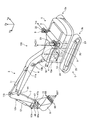
- FIG. 1 is a perspective view of a working machine according to a first embodiment.
- FIG. 2 is a diagram for explaining a vehicle body coordinate system.
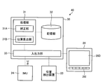
- FIG. 3 is a diagram illustrating an example of a calibration system of a work machine including the calibration device of the work machine according to the first embodiment.
- FIG. 4 is a view showing a case where the IMU has a mounting error and does not have a mounting error when the hydraulic shovel is placed on a slope.
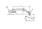
- FIG. 5 is a diagram for explaining the position of the cutting edge when the IMU has no attachment error.
- FIG. 6 is a diagram for explaining the position of the cutting edge when the IMU has a mounting error.
- FIG. 7 is a flowchart illustrating an example of processing of the calibration method of the working machine according to the first embodiment.
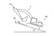
- FIG. 8 is a side view showing a state where a hydraulic shovel is installed on an inclined surface in order to correct the measurement error of the IMU.
- FIG. 9 is a view showing a first posture of the hydraulic shovel installed on the inclined surface.
- FIG. 10 is a view showing a second posture of the hydraulic shovel installed on the inclined surface.
- FIG. 11 is a side view showing a difference between the position of the work machine in the first posture and the position of the work machine in the second posture.
- FIG. 12 is a front view showing a difference between the position of the work machine in the first posture and the position of the work machine in the second posture.
- FIG. 13 is a view showing a modified example for obtaining the first attitude and the second attitude.
- FIG. 14 is a diagram showing an example of measuring the first position in the first posture in the second embodiment.
- FIG. 15 is a diagram showing an example of measuring the second position in the second posture in the second embodiment.
- FIG. 1 is a perspective view of a working machine according to a first embodiment.
- FIG. 2 is a diagram for explaining a vehicle body coordinate system.
- the work machine is the hydraulic shovel 100.
- the hydraulic shovel 100 has a vehicle body 1 and a work implement 2.
- the vehicle body 1 has a revolving unit 3, a cab 4 and a traveling unit 5.
- the revolving unit 3 is attached to the traveling unit 5 so as to be pivotable about a pivoting center axis Zr.
- the revolving unit 3 accommodates devices such as a hydraulic pump and an engine.
- the work implement 2 is attached and the revolving unit 3 is pivoted.
- the handrail 9 is attached to the upper part of the revolving unit 3.
- Antennas 21 and 22 are attached to the handrail 9.
- the antennas 21 and 22 are antennas for RTK-GNSS (Real Time Kinematic-Global Navigation Satellite Systems, GNSS means Global Navigation Satellite System).
- the antennas 21 and 22 are spaced apart by a constant distance along the Ym axis of the vehicle body coordinate system (Xm, Ym, Zm).
- the antennas 21 and 22 receive GNSS radio waves and output a signal corresponding to the received GNSS radio waves.
- the antennas 21 and 22 may be antennas for GPS (Global Positioning System).
- the operator's cab 4 is placed at the front of the revolving unit 3.
- the traveling body 5 has crawler belts 5a and 5b.
- the hydraulic shovel 100 travels as the crawler belts 5a and 5b rotate.
- the work machine 2 is attached to the front of the vehicle body 1 and includes a boom 6, an arm 7, a bucket 8, a boom cylinder 10, an arm cylinder 11 and a bucket cylinder 12.
- the base end of the boom 6 is rotatably attached to the front of the vehicle body 1 via a boom pin 13. That is, the boom pin 13 corresponds to the rotation center of the boom 6 with respect to the swing body 3.
- the proximal end of the arm 7 is rotatably attached to the distal end of the boom 6 via an arm pin 14. That is, the arm pin 14 corresponds to the rotation center of the arm 7 with respect to the boom 6.
- the bucket 8 is rotatably attached to the tip of the arm 7 via a bucket pin 15. That is, the bucket pin 15 corresponds to the rotation center of the bucket 8 with respect to the arm 7.
- the boom cylinder 10, the arm cylinder 11, and the bucket cylinder 12 shown in FIG. 1 are hydraulic cylinders driven by hydraulic pressure.
- the base end of the boom cylinder 10 is rotatably attached to the revolving unit 3 via a boom cylinder foot pin 10a.
- the tip of the boom cylinder 10 is rotatably attached to the boom 6 via a boom cylinder top pin 10b.
- the boom cylinder 10 drives the boom 6 by expanding and contracting hydraulically.
- the base end of the arm cylinder 11 is rotatably attached to the boom 6 via an arm cylinder foot pin 11a.
- the tip of the arm cylinder 11 is rotatably attached to the arm 7 via an arm cylinder top pin 11b.
- the arm cylinder 11 drives the arm 7 by expanding and contracting hydraulically.
- the base end of the bucket cylinder 12 is rotatably attached to the arm 7 via a bucket cylinder foot pin 12a.
- the tip of the bucket cylinder 12 is rotatably attached to one end of the first link member 47 and one end of the second link member 48 via the bucket cylinder top pin 12 b.
- the other end of the first link member 47 is rotatably attached to the tip of the arm 7 via a first link pin 47a.
- the other end of the second link member 48 is rotatably attached to the bucket 8 via a second link pin 48a.
- the bucket cylinder 12 drives the bucket 8 by expanding and contracting hydraulically.
- the bucket 8 has a plurality of blades 8B.
- the plurality of blades 8B are arranged in a line along the width direction of the bucket 8.
- the tip of the blade 8B is a cutting edge 8BT.
- the bucket 8 is an example of a work implement.
- the work tool is not limited to the bucket 8.
- the work tool may be, for example, a tilt bucket having a single blade, a slope bucket or a rock drilling attachment with a rock drilling tip, or any of these. Good.
- the swing body 3 includes a position detection device 23, an IMU (Inertial Measurement Unit: inertial measurement device) 24 which is an example of a posture detection device, a calibration device 30 for a working machine, and a control device 25 for controlling the hydraulic shovel 100. Is attached.
- the position detection device 23 receives signals from the antennas 21 and 22.
- the position detection device 23 detects and outputs the current position of the antennas 21 and 22 and the orientation of the rotating body 3 in the global coordinate system (Xg, Yg, Zg) using the signals acquired from the antennas 21 and 22.
- the orientation of the revolving unit 3 represents the orientation of the revolving unit 3 in the global coordinate system.
- the orientation of the swing body 3 can be represented, for example, by the longitudinal direction of the swing body 3 around the Zg axis of the global coordinate system.
- the azimuth of the rotating body 3 is represented by the azimuth angle ⁇ d.
- the azimuth angle ⁇ d is a rotation angle of the reference axis in the front-rear direction of the rotating body 3 around the Zg axis of the global coordinate system.
- the position detection device 23 calculates the azimuth angle ⁇ d from the relative position of the two antennas 21 and 22.
- the vehicle body coordinate system (Xm, Ym, Zm) described above is a coordinate system based on the origin fixed to the vehicle body 1, in the present embodiment, to the revolving unit 3.
- the origin of the vehicle body coordinate system (Xm, Ym, Zm) is, for example, the center of the swing circle of the revolving unit 3.
- the center of the swing circle is on the swing center axis Zr of the swing body 3.
- the Zm axis of the vehicle body coordinate system (Xm, Ym, Zm) is an axis serving as the turning center axis Zr of the turning body 3, and the Xm axis is an axis extending in the front-rear direction of the turning body 3 and orthogonal to the Zm axis,
- the Ym axis is an axis extending in the width direction of the revolving unit 3 which is orthogonal to the Zm axis and the Xm axis.
- the Xm axis is a reference axis in the front-rear direction of the swing body 3.
- the above-mentioned global coordinate system (Xg, Yg, Zg) is a coordinate system measured by GNSS, and is a coordinate system based on the origin fixed to the earth.
- the IMU 24 has its own coordinate system (Xi, Yi, Zi) as shown in FIG.
- the IMU 24 is installed below the cab 4.
- the IMU 24 detects an acceleration acting on the hydraulic shovel 100.
- the IMU 24 can detect an inclination angle in the width direction of the vehicle body 1, in the present embodiment, the swing body 3.
- the width direction of the vehicle body 1 is a direction parallel to the axial direction of the boom pin 13.
- the inclination angle in the width direction of the vehicle body 1 is an angle ⁇ r around the Xm axis of the vehicle body coordinate system (Xm, Ym, Zm) shown in FIG.
- the angle ⁇ r is appropriately referred to as a roll angle ⁇ r.
- the IMU 24 can detect, from the detected angular velocity, an inclination angle in the front-rear direction of the vehicle body 1 with respect to the direction in which gravity acts, in the present embodiment, the revolving unit 3.
- the longitudinal direction of the vehicle body 1 is a direction in which the Xm axis of the vehicle body coordinate system (Xm, Ym, Zm) shown in FIG. 2 extends.
- the inclination angle in the front-rear direction of the vehicle body 1 is an angle ⁇ p around the Ym axis of the vehicle body coordinate system (Xm, Ym, Zm) shown in FIG.
- the angle ⁇ p is appropriately referred to as a pitch angle ⁇ p.
- the IMU 24 can obtain information necessary for control of the hydraulic shovel 100, such as acceleration, angular velocity, roll angle ⁇ r, pitch angle ⁇ p, and yaw angle ⁇ y of the hydraulic shovel 100 with one device.
- the control device 25 controls the work machine 2 using the position of the work machine 2, for example, the position of the cutting edge 8BT of the bucket 8 in the global coordinate system.
- the roll angle ⁇ r, the pitch angle ⁇ p, and the azimuth angle ⁇ d are used to obtain the position of the work machine 2 in the global coordinate system.
- the calibration device 30 of the work machine obtains the position of the work machine 2, but the position of the work machine 2 may be obtained by the control device 25 or may be obtained by devices other than the control device 25. Good.
- FIG. 3 is a diagram showing an example of a calibration system 40 for a work machine including the calibration device 30 for a work machine according to the first embodiment.
- the work machine calibration system 40 includes a work machine calibration device 30, a position detection device 23, an IMU 24, and an input / output device 26.
- the position detection device 23 is not necessarily required in the present embodiment.
- the calibration device 30 for the work machine is appropriately referred to as a calibration device 30, and the calibration system 40 for the work machine is appropriately referred to as a calibration system 40.
- the calibration device 30 includes a processing unit 31, a storage unit 32, and an input / output unit 33.
- the processing unit 31 includes a correction unit 31A and a position calculation unit 31B.
- the processing unit 31 is, for example, a processor such as a central processing unit (CPU) and a memory.
- the processing unit 31 executes the calibration method of the working machine according to the embodiment.
- the correction unit 31A mainly installs the IMU 24 with the yaw angle shifted with respect to the front-rear direction of the hydraulic shovel 1 by executing the calibration method of the working machine according to the present embodiment, thereby generating inclination. And correct the errors contained in the detected values of the IMU 24.
- the position calculation unit 31B mainly obtains the position of the work machine 2 using the corrected detection value of the IMU 24.
- the storage unit 32 is, for example, a nonvolatile or volatile memory such as a random access memory (RAM), a random access memory (ROM), a flash memory, an erasable programmable random access memory (EPROM), and an electrically erasable programmable random access memory (EEPROM).
- RAM random access memory
- ROM random access memory
- EPROM erasable programmable random access memory
- EEPROM electrically erasable programmable random access memory
- At least one of semiconductor memory, magnetic disk, flexible disk, and magneto-optical disk is used.
- the storage unit 32 is a computer program for causing the processing unit 31 to execute the calibration method of the working machine according to the embodiment, and information used when the processing unit 31 executes the calibration method of the work machine according to the embodiment Remember.
- the processing unit 31 implements the calibration method of the working machine according to the embodiment by reading and executing the computer program described above from the storage unit 32.
- the input / output unit is an interface circuit for connecting the calibration device 30 and the devices.
- the IMU 24, the position detection device 23, and the input / output device 26 are connected to the input / output unit 33.
- the input / output device 26 has a display unit 26D and an input unit 26I.
- the display unit 26D of the input / output device 26 displays, for example, the calculation result of the calibration device 30 and the information input to the calibration device 30.
- the display unit 26D is a liquid crystal display or an organic EL (Electro Luminescence) display or the like, but is not limited thereto.
- the input unit 26I is a button-type input key for inputting information to the calibration device 30, but is not limited to such.
- the IMU 24 can not be disposed at the turning center of the turning body 3 which is the reference position of the car body coordinate system, the coordinate system (Xi, Yi, Zi) of the IMU 24 and the car body coordinate system (Xm, Ym, Zm) It is different.
- the IMU 24 can be obtained from the angular velocity and acceleration detected by the IMU 24 if the Xi axis of the IMU 24 coordinate system (Xi, Yi, Zi) and the Xm axis of the vehicle coordinate system (Xm, Ym, Zm) are parallel. The accuracy of the roll angle ⁇ r and the pitch angle ⁇ p is guaranteed.
- the Xi axis is the reference axis of the IMU 24.
- the IMU 24 When the Xi axis of the IMU 24 has a yaw angle offset with respect to the Xm axis of the vehicle body coordinate system, ie, has an angle offset, the IMU 24 attached to the revolving unit 3 which is a part of the hydraulic shovel 100 It has an angular deviation with respect to it. Hereinafter, this angular deviation is appropriately referred to as a mounting error.
- the deviation of the IMU 24 relative to the hydraulic shovel 100 is shown.
- the pitch angle ⁇ p and the roll angle ⁇ r of the hydraulic shovel 100 detected by the IMU 24 and recognized by the calibration device 30 include errors. That is, the detection value of the IMU 24 includes an error due to the mounting error of the IMU 24.
- this error is appropriately referred to as a measurement error.
- FIG. 4 is a view showing the case where the IMU 24 has and does not have a mounting error when the hydraulic shovel 100 is placed on the inclined surface PD.
- FIG. 5 is a diagram for explaining the position of the cutting edge 8BT when the IMU 24 has no mounting error.
- FIG. 6 is a diagram for explaining the position of the cutting edge 8BT when the IMU 24 has a mounting error.
- FIG. 4 shows the state of the IMU 24 when the hydraulic shovel 100 shown in FIG. 1 is placed on the inclined surface PD where the inclination angle from the horizontal surface is ⁇ .
- a in FIG. 4 shows the case where the Xi axis of the coordinate system of the IMU 24 is parallel to the Xm axis of the vehicle coordinate system. That is, the case where the IMU 24 has no mounting error is shown.
- B in FIG. 4 shows the case where the Xi axis of the coordinate system of the IMU 24 and the Xm axis of the vehicle coordinate system are not parallel. This example shows the case where the IMU 24 has a mounting error.
- the swivel body 3 the Xi axis of the coordinate system of IMU 24 is the vehicle coordinates It is in a state of being shifted by an angle ⁇ y with respect to the Xm axis of the system. That is, the IMU 24 is mounted in a state where a shift in the yaw direction occurs with respect to the front-rear direction of the hydraulic shovel 100.
- the pitch angle ⁇ p is 0 degrees
- the roll angle ⁇ r is ⁇ .
- the pitch angle ⁇ p has a value different from 0 degrees
- the roll angle ⁇ r has a value different from ⁇ .
- the actual height of the cutting edge 8BT of the bucket 8 of the work machine 2 is Hr, and the height of the cutting edge 8BT of the bucket 8 recognized by the calibration device 30 shown in FIG. .
- the height Hb is the same as the actual height Hr.
- the actual height Hr is the height from the reference surface PH to the position of the cutting edge 8BT.
- the mounting error of the IMU 24 is about ⁇ 1 degree.
- the height Hb of the cutting edge 8BT recognized by the calibration device 30 includes an error.
- the height Hb of the cutting edge 8 BT recognized by the calibration device 30 causes the work machine 2 to operate along the design surface. It may include errors to the extent that the accuracy to perform can not be guaranteed.
- the pitch angle ⁇ p affects the position of the blade edge 8BT of the bucket 8
- the roll angle ⁇ r affects the parallelism of the blade edge of the bucket 8.
- Skew correction is performed. It has been found that when the hydraulic shovel 1 becomes large, the mounting error of the IMU 24 has a large effect on the error of the pitch angle ⁇ p on the inclined surface, and therefore the positional accuracy of the cutting edge 8BT on the inclined surface is affected. Therefore, in this embodiment, the measurement error of the IMU 24 is corrected.
- the error included in the height Hb of the blade tip 8BT recognized by the calibration device 30 is the maximum when the direction from the lower side of the slope on which the hydraulic shovel 100 is placed upward to the Xm axis of the vehicle body coordinate system is orthogonal It becomes.
- the calibration device 30 and the calibration method according to the present embodiment correct the measurement error by correcting the detection value of the IMU 24 when the IMU 24 has a mounting error.
- the calibration device 30 executes the calibration method according to the present embodiment to correct the measurement error of the IMU 24 will be described.
- FIG. 7 is a flowchart illustrating an example of processing of the calibration method of the working machine according to the first embodiment.
- FIG. 8 is a side view showing the hydraulic shovel 100 installed on the inclined surface PD in order to correct the measurement error of the IMU 24.
- FIG. 9 is a view showing a first posture FF of the hydraulic shovel 100 installed on the inclined surface PD.
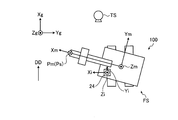
- FIG. 10 is a view showing a second posture FS of the hydraulic shovel 100 installed on the inclined surface PD.
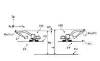
- FIG. 11 is a side view showing the difference between the position of the work implement 2 in the first posture FF and the position of the work implement 2 in the second posture FS.
- FIG. 12 is a front view showing a difference between the position of the work implement 2 in the first posture FF and the position of the work implement 2 in the second posture FS.
- the hydraulic shovel 100 having the IMU 24 to be corrected is installed on the inclined surface PD having the inclination angle ⁇ .
- the correction unit 31A of the calibration device 30 obtains the first position Pf, which is the position of the portion Pm of the hydraulic shovel 100 when the hydraulic shovel 100 is in the first posture FF shown in FIGS. (Step S101).
- the correction unit 31A of the calibration device 30 acquires a second position Ps, which is the position of the portion Pm of the hydraulic shovel 100 when the hydraulic shovel 100 has the second posture FS shown in FIGS. 10 and 11. (Step S102).
- the first position Pf is a position where the hydraulic shovel 100 is installed on the inclined surface PD and the swing body 3 is facing in the first direction
- the second position Ps is a position where the hydraulic shovel 100 is on the inclined surface PD It is a position in which it is installed and turning object 3 has turned to the 2nd direction. That is, the first position Pf and the second position Ps are two different positions when the orientation of the swing body 3 is different.
- the part Pm of the hydraulic shovel 100 may be a part of the swing body 3 and the work implement 2 attached thereto, and may be a position other than the center of rotation of the swing body 3.
- a portion Pm is a portion of the work implement 2, more specifically, a portion of the arm cylinder top pin 11b shown in FIG. 1, but is not limited to this portion.
- the first attitude FF and the second attitude FS are attitudes when the pitch angle ⁇ p output by the IMU 24 is 0 degree. That is, the first position Pf and the second position Ps are positions when the pitch angle ⁇ p output by the IMU 24 is 0 degree.
- a direction from the lower side to the upper side of the inclined surface PD is taken as an inclined direction DD.
- the angle between the inclination direction DD and the horizontal plane is the inclination angle ⁇ .
- the direction orthogonal to the tilt direction DD is parallel to the horizontal plane.
- the case where the pitch angle ⁇ p output by the IMU 24 is 0 degrees is the case where the Yi axis in the coordinate system of the IMU 24 is parallel to the tilt direction DD.
- the second posture FS is a posture in which the posture of the work machine 2 is different from that of the first posture FF.
- the swing body 3 turns from the state of the first posture FF in which the pitch angle ⁇ p output by the IMU 24 is 0 degree, and the pitch angle ⁇ p output by the IMU 24 is 0 again Attitude when it comes to In this case, the swing body 3 swings 180 degrees.
- the first position Pf and the second position Ps are two different positions when the orientation of the swing body 3 differs by 180 degrees, but the present invention is not limited to such a positional relationship.
- the first position Pf and the second position Ps may be two different positions when the orientation of the swing body 3 is different by a size other than 180 degrees. In this case, it is necessary to correct the first position Pf and the second position Pf in accordance with the size between two different orientations. It is preferable to set the first position Pf and the second position Ps as two different positions when the orientation of the revolving unit 3 differs by 180 degrees, since the correction of the first position Pf and the second position Pf becomes unnecessary.
- the first position Pf and the second position Ps are measured by the external measuring device TS shown in FIGS. 9 and 10.
- the external measurement device TS is, for example, a measurement device called a total station, but is not limited to this.
- the first position Pf and the second position Ps are positions in the global coordinate system (Xg, Yg, Zg), but are not limited thereto.
- the first position Pf and the second position Ps may be input to the calibration device 30 from the input / output device 26 shown in FIG. Further, by connecting the external measurement device TS to the input / output unit 33 of the calibration device 30, the calibration device 30 may obtain the first position Pf and the second position Ps directly from the external measurement device TS.
- the first position Pf and the second position Ps are different.
- the height Hf of the first position Pf from the reference plane PH and the height Hs of the second position Ps from the reference plane PH are different.
- a difference ⁇ h between the height Hf and the height Hs occurs.
- the error D of the height of the portion Pm due to the mounting error of the IMU 24 is ⁇ h / 2.
- the correction unit 31A of the calibration device 30 corrects the measurement error of the IMU 24 using the first position Pf and the second position Ps (step S103).
- the calibration device 30 corrects the measurement error of the IMU 24 using the error D obtained from the difference ⁇ h between the first position Pf and the second position Ps.
- the relationship between the true pitch angle ⁇ pt2 at the second attitude FS, the error D, and the distance L from the origin of the vehicle body coordinate system to the part Pm of the work machine 2 is calculated using the inclination angle ⁇ and the angle ⁇ y. It is calculated by the equation (1).
- the distance L is a distance from the origin of the vehicle body coordinate system to a part Pm, and is a distance in the Xm direction of the vehicle body coordinate system.
- the distance L is obtained from the attitude and dimensions of the work implement 2.
- the inclination angle ⁇ is an inclination angle of the inclined surface PD on which the hydraulic shovel 100 is installed when measuring the first position Pf and the second position Ps.
- the inclination angle ⁇ is a peak value of the roll angle ⁇ r detected and output by the IMU 24 when the swing body 3 turns when the hydraulic shovel 100 changes from the first attitude FF to the second attitude FS.
- ⁇ y is a yaw angle error.
- the yaw angle error ⁇ y is an angle formed between the Xi axis and the Xm axis when the Xi axis of the coordinate system of the IMU 24 is shifted with respect to the Xm axis of the vehicle body coordinate system.
- the yaw angle error ⁇ y is an error generated when the IMU 24 is attached to the hydraulic shovel 100, in this embodiment, the swing body 3 by rotating around the Zi axis.
- Equation (2) is obtained by modifying equation (1) and solving for the yaw angle error ⁇ y.
- ⁇ y sin ⁇ 1 ⁇ (D / L) ⁇ (1 / sin ⁇ ) ⁇ (2)
- the correction unit 31A of the calibration device 30 obtains the yaw angle error ⁇ y by giving the error D, the distance L, and the inclination angle ⁇ obtained from the detection value of the IMU 24 to Expression (2).
- the correction unit 31A of the calibration device 30 stores the obtained yaw angle error ⁇ y in the storage unit 32 shown in FIG.
- the processing unit 31 of the calibration device 30, more specifically, the position calculation unit 31B shown in FIG. 3 reads the yaw angle error ⁇ y from the storage unit 32, and uses this to detect and output the acceleration and angle detected by the IMU 24. Correct the
- the equation (3) indicates the correction values Gxn, Gyn, Gzn of the acceleration that the IMU 24 detects and outputs.
- the position calculation unit 31B corrects the equation (3) with the yaw angle error ⁇ y.
- the position calculation unit 31B corrects the angle acquired from the IMU 24, in the present embodiment, the pitch angle ⁇ p and the roll angle ⁇ r, using the yaw angle error ⁇ y.
- Formula (4) shows roll angle (theta) rn after correction
- Formula (5) shows pitch angle (theta) pn after correction
- the position calculation unit 31 B gives the yaw angle error ⁇ y read from the storage unit 32 and the roll angle ⁇ r and the pitch angle ⁇ p output from the IMU 24 to the equations (4) and (5), thereby correcting the corrected roll angle ⁇ rn.
- the pitch angle ⁇ pn after correction is determined.
- the position of the work implement 2 is determined using the corrected roll angle ⁇ rn, the corrected pitch angle ⁇ pn, and the azimuth angle ⁇ d.
- a cutting edge position the position of the cutting edge 8BT of the bucket 8 (hereinafter, referred to as a cutting edge position) is obtained as the position of the work machine 2.
- the blade position is PB
- the blade position PB in the vehicle body coordinate system (Xm, Ym, Zm) can be obtained from the dimensions and posture of the work machine 2.
- the obtained blade tip position PB is converted from the vehicle body coordinate system (Xm, Ym, Zm) to the value of the global coordinate system (Xg, Yg, Zg), for example, by the equation (1).
- PBg R ⁇ PBm + T (6)
- PBg is the edge position PB in the global coordinate system (Xg, Yg, Zg)
- PBm is the edge position PB in the vehicle coordinate system
- R is the rotation matrix shown in the equation (7)
- T is the equation (8) It is a translation vector shown by).
- the rotation matrix R includes the roll angle ⁇ r, the pitch angle ⁇ p, and the azimuth angle ⁇ d.
- the roll angle ⁇ r and the pitch angle ⁇ p are values that the IMU 24 detects and outputs.
- the azimuth angle ⁇ d is a value calculated and output from the relative position of the antennas 21 and 22 by the position detection device 23.
- the translational vector T is obtained from the positional relationship between the positions of the antennas 21 and 22 in the global coordinate system (Xg, Yg, Zg) detected by the position detection device 23 and the vehicle body coordinate system (Xm, Ym, Zm) .
- the true pitch angle ⁇ pt2 at the second posture FS can be obtained by the equation (9) using the error D and the distance L from the origin of the vehicle body coordinate system to the part Pm of the work machine 2.
- ⁇ pt2 sin ⁇ 1 (D / L) (9)
- the correction unit 31A of the calibration device 30 obtains the true pitch angle ⁇ pt2 using Expression (9).
- the relationship between the true pitch angle ⁇ pt2, the yaw angle error ⁇ y, and the roll angle ⁇ r and the pitch angle ⁇ p detected and output by the IMU 24 can be obtained from the equations (4) and (5).
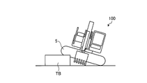
- FIG. 13 is a view showing a modified example for obtaining the first posture FF and the second posture FS.
- the hydraulic shovel 100 is installed on the inclined surface PD.
- a posture similar to that when the hydraulic shovel 100 is installed on the inclined surface PD can be created. it can.
- the calibration apparatus 30 can correct the measurement error caused by the mounting error of the IMU 24 by preparing the table TB even in a place where the inclined surface PD does not exist.
- the present embodiment and the modification thereof correct the error included in the detection value of the IMU 24 caused by the occurrence of the inclination by the IMU 24 being installed with the yaw angle shifted with respect to the front-rear direction of the hydraulic shovel 100 can do.
- the mounting error in the yaw direction of IMU 24 hardly affects the accuracy when the position of work implement 2 is determined when the body 1 of hydraulic excavator 100 to which IMU 24 is attached is horizontal, but the hydraulic excavator on slopes When 100 is placed, the accuracy in determining the position of the work implement 2 decreases. In particular, in the posture in which the vehicle body 1 of the hydraulic shovel 100 rolls, the accuracy when the position of the work machine 2 is obtained is lowered.
- the present embodiment and the modification thereof use IMU 24 by using two positions of a part of hydraulic excavator 100, which is measured in two attitudes including at least one attitude in which vehicle body 1 of hydraulic excavator 100 is inclined. Correct the measurement error caused by the mounting error of. As described above, since at least one, and in the present embodiment, two, postures in which the hydraulic shovel 100 inclined in which the mounting error of the IMU 24 is likely to be affected in the yaw direction is inclined, measurement errors due to the mounting error of the IMU 24 A correction amount for correcting the image is easily obtained.
- the first position FF is the first position FF in which the vehicle body 1 of the hydraulic shovel 100 rolls, that is, the first position FF and the second position FS in which the pitch angle ⁇ p output by the IMU 24 is 0 degrees.
- Pf and the second position Ps are measured. From the first position Pf and the second position Ps measured in this manner, a correction amount for correcting the mounting error of the IMU 24 in the yaw direction, that is, the yaw angle error ⁇ y is obtained.
- the first position Pf and the second position Ps are obtained in the posture in which the accuracy of the position of the work machine 2 is greatly reduced, the difference between the two becomes large. As a result, the influence of the measurement error of the first position Pf and the second position Ps can be reduced, so that the above-described decrease in accuracy of the correction amount is suppressed.
- the IMU 24 can correct the pitch angle ⁇ p and the roll angle ⁇ r detected and output with high accuracy. . Further, in the present embodiment and the modification thereof, since the measurement using the positioning satellite such as the GPS becomes unnecessary by the external measurement device TS, it is not influenced by the positioning error in the measurement using the positioning satellite. As a result, according to this embodiment and its modification, the pitch angle ⁇ p and the roll angle ⁇ r detected and output by the IMU 24 can be corrected with high accuracy.
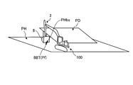
- FIG. 14 is a diagram illustrating an example of measuring the first position Pf at the first posture FF in the second embodiment.
- FIG. 15 is a diagram illustrating an example of measuring the second position Ps in the second posture FS in the second embodiment.
- the hydraulic shovel 100, the position detection device 23, the IMU 24, the control device 25, the calibration device 30, and the calibration system 40 are the same as in the first embodiment, and thus the description thereof is omitted.
- a processing example of the calibration method of the working machine according to the second embodiment will be described using the flowchart shown in FIG. 7.
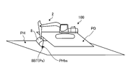
- the first position Pf and the second position Ps shown in FIG. 14 are obtained based on a part of the hydraulic shovel 100, in this example, a position other than the hydraulic shovel 100 (hereinafter referred to as measurement position as appropriate) Also, it is the position of a part Pm of the work implement 2.
- the measurement position is a part PHbs of the reference surface PH.
- the measurement position may be immobile or the same position when the first position Pf is measured and the second position Ps is measured, and is not limited to the part PHbs of the reference surface PH.
- a part PHbs of the reference surface PH is appropriately referred to as a measurement position PHbs.
- the first position Pf and the second position Ps are obtained using the information on the posture of the hydraulic shovel 100 output from the IMU 24.
- As information on the posture of the hydraulic shovel 100 a roll angle ⁇ r, a pitch angle ⁇ p, and an azimuth angle ⁇ d are exemplified.
- a part Pm of the work machine 2 is a cutting edge 8BT of the bucket 8.
- the first position Pf is the position of the cutting edge 8BT when the cutting edge 8BT contacts the measurement position PHbs when the hydraulic shovel 100 has the first posture FF.
- the second position Ps is the position of the cutting edge 8BT when the cutting edge 8BT contacts the measurement position PHbs when the hydraulic shovel 100 has the second posture FS.
- the first position Pf and the second position Ps are obtained in a state where the same cutting edge 8BT of the bucket 8 is in contact with the same portion of the reference point.
- the position of the blade tip 8BT using the roll angle ⁇ r and the pitch angle ⁇ p which are information related to the attitude of the hydraulic shovel 100 output from the IMU 24.
- the position azimuth angle ⁇ d of the work machine 2 and the attitude and dimensions of the work machine 2 are used to obtain the position of the cutting edge 8BT.
- the first posture FF is a posture of the hydraulic shovel 100 in a state where the hydraulic shovel 100 is installed on the reference plane PH.
- the second posture FS is a posture of the hydraulic shovel 100 in a state where the hydraulic shovel 100 is installed on the inclined surface PD which is inclined with respect to the reference surface PH.
- the correction unit 31A of the calibration device 30 acquires the first position Pf when the hydraulic shovel 100 is in the first posture FF (step S101 in FIG. 7).
- the correction unit 31A of the calibration device 30 acquires the second position Ps when the hydraulic shovel 100 is in the second posture FS (step S102 in FIG. 7).
- the first position Pf and the second position Ps do not match. If the yaw angle error ⁇ y exists, the pitch angle ⁇ p and the roll angle ⁇ r output by the IMU 24 also include errors.
- the correction unit 31A of the calibration device 30 shown in FIG. 3 corrects the yaw angle error ⁇ y, and the correction is performed using the aforementioned equations (4) and (5).
- the pitch angle ⁇ pn of and the roll angle ⁇ rn after correction are determined.
- the position calculation unit 31B recalculates the first position Pf and the second position Ps using the corrected pitch angle ⁇ pn and the corrected roll angle ⁇ rn.
- the correction unit 31A obtains a difference between the first position Pf and the second position Ps obtained by the position calculation unit 31B (hereinafter referred to as a position difference as appropriate), and compares it with a threshold. The correction unit 31A determines whether the position difference has become equal to or less than a threshold. When the position difference is larger than the threshold, the correction unit 31A and the position calculation unit 31B repeat the correction of the yaw angle error ⁇ y and the recalculation of the first position Pf and the second position Ps until the position difference becomes equal to or less than the threshold. The correction unit 31A stores the yaw angle error ⁇ y when the difference between the first position Pf and the second position Ps becomes equal to or less than the threshold in the storage unit 32 shown in FIG.
- the position calculation unit 31B reads the yaw angle error ⁇ y from the storage unit 32, detects the IMU 24 using Equations (4) and (5), and corrects the output acceleration and the pitch angle ⁇ p and the roll angle ⁇ r.
- the calibration apparatus 30 corrects the measurement error of the IMU 24 using the yaw angle error ⁇ y obtained using the first position Pf and the second position Ps (step S103 in FIG. 7).
- the correction unit 31A repeats the recalculation of the first position Pf and the second position Ps while performing correction using a parameter for correcting information on the attitude of the hydraulic shovel 100, in the present embodiment, the yaw angle error ⁇ y. Then, the correction unit 31A of the calibration device 30 uses the yaw angle error ⁇ y when the difference between the first position Pf and the second position Ps (hereinafter appropriately referred to as a position difference) becomes equal to or less than the threshold value. Correct the measurement error caused by the mounting error of.
- the calibration device 30 can correct the error included in the detection value of the IMU 24 caused by the occurrence of the deviation in the yaw direction due to the IMU 24 tilting relative to the front-rear direction of the hydraulic shovel 100 it can.
- the correction unit 31A determines, for example, an initial value of the yaw angle error ⁇ y, and a direction in which the yaw angle error ⁇ y increases and decreases from the initial value.
- the yaw angle error .DELTA..theta. Y is changed by a predetermined amount from the initial value.
- the initial value of the yaw angle error ⁇ y can be 0 degrees
- the predetermined magnitude can be 0.01 degrees, but is not limited to these values.
- the threshold value to be compared with the position difference is not limited, for example, the absolute value of the distance is used.
- the threshold can be, for example, about the measurement error of GNSS.
- the yaw angle ⁇ y when the difference between the first position Pf and the second position Ps obtained by recalculation is equal to or less than a predetermined ratio of the difference between the first position Pf and the second position Ps before correction.
- the measurement error may be corrected using
- the threshold is a predetermined ratio of the difference between the first position Pf and the second position Ps before correction.
- the predetermined percentage can be, for example, 1% or 5%, but is not limited to these values.
- the position calculation unit 31B corrects the yaw angle error ⁇ y.
- the position calculation unit 31B corrects the roll angle ⁇ r and the pitch angle ⁇ p detected and output by the IMU 24 by using, as a correction value, the yaw angle error ⁇ y when the position difference becomes equal to or less than the threshold.
- the present embodiment is caused by the mounting error of the IMU 24 using the position of a part of the hydraulic shovel 100 measured in two postures including at least one posture in which the vehicle body 1 of the hydraulic shovel 100 is inclined. Correct the measurement error. At this time, the position of a part of the hydraulic shovel 100 is measured based on the measurement position PHbs other than the hydraulic shovel 100. As described above, the present embodiment uses at least one posture in which the hydraulic shovel 100 is inclined, which is easily affected by the mounting error of the IMU 24 in the yaw direction. Therefore, the correction amount for correcting the mounting error of the IMU 24 in the yaw direction Is easily obtained. In the present embodiment, since the external measuring device TS is unnecessary, even in a place without the external measuring device TS, for example, at a work site of the hydraulic shovel 100, it is possible to correct the measurement error caused by the mounting error of the IMU 24.
- the blade tip 8BT of the bucket 8 is brought into contact with the measurement position PHbs of the reference surface PH, but if the positional relationship between the blade tip 8BT and the measurement position PHbs is known, the measurement position PHbs and the blade tip 8BT are not in contact with each other. It is also good.
- the calibration device 30 may obtain the first position Pf and the second position Ps using the output of the IMU 24 when the blade tip 8BT is stopped at a predetermined position above the measurement position PHbs in the vertical direction.
- the first position Pf and the second position Ps may be positions of parts of the hydraulic shovel 100 obtained based on the position other than the hydraulic shovel 100.
- the position of a part of the hydraulic shovel 100 is not limited to the cutting edge 8 BT of the bucket 8, and may be, for example, the bottom of the bucket 8 or a part of the second link member 48 shown in FIG.
- Embodiment 1 the modification, and Embodiment 2 were described, these are not limited by the content mentioned above.
- the above-mentioned constituent elements include those which can be easily conceived by those skilled in the art, substantially the same ones, and so-called equivalent ranges.
- the components described above can be combined as appropriate.
- various omissions, replacements, or changes of the components can be made without departing from the subject matter of the first embodiment, its modification, and the second embodiment.
- Reference Signs List 1 vehicle body 2 work machine 3 revolving body 4 cab 5 traveling body 6 boom 7 arm 8 bucket 8B blade 8 BT blade edge 10 boom cylinder 11 arm cylinder 12 bucket cylinder 13 boom pin 14 arm pin 15 bucket pin 23 position detection device 25 control device 26 input / output Device 30 Calibration device 31 Processing unit 31A Correction unit 31B Position calculation unit 32 Storage unit 33 Input / output unit 40 Calibration system 100 Hydraulic shovel D Error FF First attitude FS Second attitude L Distance PD Slope Pf First position PH Reference Surface PHbs Measurement position Pm Partial Ps Second position TB Table TS External measurement device ⁇ r Roll angle ⁇ p Pitch angle ⁇ y Yaw angle ⁇ Inclination angle ⁇ y Yaw angle error
Landscapes
- Engineering & Computer Science (AREA)
- Mining & Mineral Resources (AREA)
- Civil Engineering (AREA)
- General Engineering & Computer Science (AREA)
- Structural Engineering (AREA)
- Mechanical Engineering (AREA)
- Operation Control Of Excavators (AREA)
- Component Parts Of Construction Machinery (AREA)
- Length Measuring Devices With Unspecified Measuring Means (AREA)
Abstract
Description
<作業機械の全体構成>
図1は、実施形態1に係る作業機械の斜視図である。図2は、車体座標系を説明するための図である。本実施形態において、作業機械は油圧ショベル100である。油圧ショベル100は、車体1及び作業機2を有する。車体1は、旋回体3、運転室4及び走行体5を有する。旋回体3は、走行体5に、旋回中心軸Zrを中心として旋回可能に取り付けられている。旋回体3は、油圧ポンプ及びエンジン等の装置を収容している。
図3は、実施形態1に係る作業機械の校正装置30を含む作業機械の校正システム40の一例を示す図である。作業機械の校正システム40は、作業機械の校正装置30と、位置検出装置23と、IMU24と、入出力装置26とを含む。本実施形態において位置検出装置23は必ずしも必要ではない。以下において、作業機械の校正装置30を適宜、校正装置30と称し、作業機械の校正システム40を適宜、校正システム40と称する。
図7は、実施形態1に係る作業機械の校正方法の処理例を示すフローチャートである。図8は、IMU24の計測誤差を補正するために油圧ショベル100を傾斜面PDに設置した状態を示す側面図である。図9は、傾斜面PDに設置された油圧ショベル100の第1の姿勢FFを示す図である。図10は、傾斜面PDに設置された油圧ショベル100の第2の姿勢FSを示す図である。図11は、第1の姿勢FFにおける作業機2の位置と第2の姿勢FSにおける作業機2の位置との差を示す側面図である。図12は、第1の姿勢FFにおける作業機2の位置と第2の姿勢FSにおける作業機2の位置との差を示す正面図である。
sinθpt2=D/L=sinφ×sinΔθy・・・(1)
Δθy=sin-1{(D/L)×(1/sinφ)}・・・(2)



PBg=R・PBm+T・・・(6)


第2の姿勢FSのときにおける真のピッチ角θpt2は、誤差D及び車体座標系の原点から作業機2の一部分Pmまでの距離Lを用いると、式(9)で求められる。
θpt2=sin-1(D/L)・・・(9)
図13は、第1の姿勢FF及び第2の姿勢FSを得るための変形例を示す図である。前述した例では、図8に示されるように、油圧ショベル100を傾斜面PDに設置した。変形例は、図13に示されるように、油圧ショベル100の走行体5の一部を台TBに乗り上げさせることにより、油圧ショベル100を傾斜面PDに設置した場合と同様の姿勢を作り出すことができる。台TBを用いることにより、傾斜面PDが存在しない場所でも、台TBを用意することにより、校正装置30は、IMU24の取付誤差に起因する計測誤差を補正することができる。
図14は、実施形態2において、第1の姿勢FFで第1位置Pfを計測する例を示す図である。図15は、実施形態2において、第2の姿勢FSで第2位置Psを計測する例を示す図である。本実施形態において、油圧ショベル100、位置検出装置23、IMU24、制御装置25、校正装置30及び校正システム40は、実施形態1と同様なので、説明を省略する。次においては、図7に示されるフローチャートを用いて、実施形態2に係る作業機械の校正方法の処理例が説明される。
2 作業機
3 旋回体
4 運転室
5 走行体
6 ブーム
7 アーム
8 バケット
8B 刃
8BT 刃先
10 ブームシリンダ
11 アームシリンダ
12 バケットシリンダ
13 ブームピン
14 アームピン
15 バケットピン
23 位置検出装置
25 制御装置
26 入出力装置
30 校正装置
31 処理部
31A 補正部
31B 位置算出部
32 記憶部
33 入出力部
40 校正システム
100 油圧ショベル
D 誤差
FF 第1の姿勢
FS 第2の姿勢
L 距離
PD 傾斜面
Pf 第1位置
PH 基準面
PHbs 計測位置
Pm 一部分
Ps 第2位置
TB 台
TS 外部計測装置
θr ロール角
θp ピッチ角
θy ヨー角
φ 傾斜角
Δθy ヨー角誤差
Claims (9)
- 作業機が取り付けられて旋回する旋回体を有する作業機械の姿勢を出力する姿勢検出装置の前記作業機械に対するずれに起因する誤差を補正するにあたり、
前記作業機械が第1の姿勢であるときにおける前記作業機械の一部分の位置である第1位置と、前記作業機械が第2の姿勢であるときにおける前記一部分の位置である第2位置とを用いて前記誤差を補正する、作業機械の校正装置。 - 前記一部分の位置は、前記作業機の一部の位置であり、
前記第1位置は、前記作業機械が傾斜面に設置され、かつ前記旋回体が第1の方向を向いているときの位置であり、
前記第2位置は、前記作業機械が傾斜面に設置され、かつ前記旋回体が第2の方向を向いているときの位置である、
請求項1に記載の作業機械の校正装置。 - 前記第1位置及び前記第2位置は、前記姿勢検出装置が出力したピッチ角が0度のときの位置である、請求項2に記載の作業機械の校正装置。
- 前記一部分の位置は、前記作業機械が有する前記作業機の一部分の位置である、請求項1から請求項3のいずれか1項に記載の作業機械の校正装置。
- 前記第1位置及び前記第2位置は、前記作業機械以外の位置を基準として得られた前記一部分の位置であり、前記姿勢検出装置から出力された、前記作業機械の姿勢に関する情報を用いて求められる、請求項1に記載の作業機械の校正装置。
- 前記作業機械の姿勢に関する情報を補正するためのパラメータを補正しながら、前記第1位置及び前記第2位置の再計算を繰り返し、前記第1位置と前記第2位置との差が閾値以下になったときの前記パラメータを用いて前記誤差を補正する、請求項5に記載の作業機械の校正装置。
- 前記作業機械の姿勢に関する情報は、前記姿勢検出装置が出力したピッチ角及びロール角である、請求項6に記載の作業機械の校正装置。
- 請求項1から請求項7のいずれか1項に記載の作業機械の校正装置を有する、作業機械。
- 作業機が取り付けられて旋回する旋回体を有する作業機械の姿勢を出力する姿勢検出装置の前記作業機械に対するずれに起因する誤差を補正するにあたり、
前記作業機械が第1の姿勢であるときにおける前記作業機械の一部分の位置である第1位置を取得し、
前記作業機械が第2の姿勢であるときにおける前記一部分の位置である第2位置を取得し、
前記第1位置及び前記第2位置を用いて前記誤差を補正する、作業機械の校正方法。
Priority Applications (6)
| Application Number | Priority Date | Filing Date | Title |
|---|---|---|---|
| DE112015006905.4T DE112015006905T5 (de) | 2015-10-28 | 2015-10-28 | Kalibriervorrichtung einer Arbeitsmaschine, Arbeitsmaschine und Kalibrierverfahren einer Arbeitsmaschine |
| CN201580080350.6A CN107614803B (zh) | 2015-10-28 | 2015-10-28 | 作业机械的校正装置、作业机械以及作业机械的校正方法 |
| US15/574,951 US10968607B2 (en) | 2015-10-28 | 2015-10-28 | Calibration device of work machine, work machine, and calibration method of work machine |
| PCT/JP2015/080375 WO2017072877A1 (ja) | 2015-10-28 | 2015-10-28 | 作業機械の校正装置、作業機械及び作業機械の校正方法 |
| KR1020177033468A KR101972558B1 (ko) | 2015-10-28 | 2015-10-28 | 작업 기계의 교정 장치, 작업 기계 및 작업 기계의 교정 방법 |
| JP2017547249A JP6701224B2 (ja) | 2015-10-28 | 2015-10-28 | 作業機械の校正装置、作業機械及び作業機械の校正方法 |
Applications Claiming Priority (1)
| Application Number | Priority Date | Filing Date | Title |
|---|---|---|---|
| PCT/JP2015/080375 WO2017072877A1 (ja) | 2015-10-28 | 2015-10-28 | 作業機械の校正装置、作業機械及び作業機械の校正方法 |
Publications (1)
| Publication Number | Publication Date |
|---|---|
| WO2017072877A1 true WO2017072877A1 (ja) | 2017-05-04 |
Family
ID=58629962
Family Applications (1)
| Application Number | Title | Priority Date | Filing Date |
|---|---|---|---|
| PCT/JP2015/080375 Ceased WO2017072877A1 (ja) | 2015-10-28 | 2015-10-28 | 作業機械の校正装置、作業機械及び作業機械の校正方法 |
Country Status (6)
| Country | Link |
|---|---|
| US (1) | US10968607B2 (ja) |
| JP (1) | JP6701224B2 (ja) |
| KR (1) | KR101972558B1 (ja) |
| CN (1) | CN107614803B (ja) |
| DE (1) | DE112015006905T5 (ja) |
| WO (1) | WO2017072877A1 (ja) |
Cited By (9)
| Publication number | Priority date | Publication date | Assignee | Title |
|---|---|---|---|---|
| WO2018168553A1 (ja) * | 2017-03-17 | 2018-09-20 | 日立建機株式会社 | 建設機械 |
| JP2020033747A (ja) * | 2018-08-29 | 2020-03-05 | 日立建機株式会社 | 建設機械 |
| WO2020066409A1 (ja) * | 2018-09-28 | 2020-04-02 | 株式会社小松製作所 | 作業機械のためのシステム及び方法 |
| WO2020137275A1 (ja) * | 2018-12-27 | 2020-07-02 | 日立建機株式会社 | 作業機械 |
| JP2021127993A (ja) * | 2020-02-10 | 2021-09-02 | 大成建設株式会社 | 重機械の方位計測方法 |
| KR20210151964A (ko) * | 2019-06-06 | 2021-12-14 | 히다찌 겐끼 가부시키가이샤 | 건설 기계 |
| CN115298395A (zh) * | 2020-06-25 | 2022-11-04 | 株式会社小松制作所 | 用于校正作业机械的方位的系统以及方法 |
| WO2023047793A1 (ja) * | 2021-09-22 | 2023-03-30 | 株式会社小松製作所 | 作業機械を制御するためのシステム及び方法 |
| JP2023088220A (ja) * | 2021-12-14 | 2023-06-26 | 日立建機株式会社 | 建設機械 |
Families Citing this family (18)
| Publication number | Priority date | Publication date | Assignee | Title |
|---|---|---|---|---|
| JP6714534B2 (ja) * | 2017-03-29 | 2020-06-24 | 日立建機株式会社 | 建設機械 |
| DE102018200060B4 (de) | 2018-01-04 | 2024-05-08 | Robert Bosch Gmbh | Verfahren zum Betreiben einer mobilen Arbeitsmaschine und mobile Arbeitsmaschine |
| KR102687696B1 (ko) * | 2018-10-03 | 2024-07-22 | 스미도모쥬기가이고교 가부시키가이샤 | 쇼벨 |
| JP7153594B2 (ja) * | 2019-03-26 | 2022-10-14 | 日立建機株式会社 | 較正作業支援システム |
| US11274416B2 (en) | 2019-04-10 | 2022-03-15 | Deere & Company | Method of calibrating a sensor on a work vehicle |
| JP7255364B2 (ja) * | 2019-05-31 | 2023-04-11 | セイコーエプソン株式会社 | 移動体、センサーモジュール及びセンサーモジュールの較正方法 |
| JP7842526B2 (ja) * | 2020-04-17 | 2026-04-08 | 株式会社小松製作所 | 作業機械の測位システム、作業機械及び作業機械の測位方法 |
| JP7089550B2 (ja) * | 2020-06-16 | 2022-06-22 | 日立建機株式会社 | 建設機械 |
| US11624169B2 (en) | 2020-06-18 | 2023-04-11 | Deere & Company | Excavator with improved movement sensing |
| JP7009590B1 (ja) * | 2020-10-20 | 2022-01-25 | 日立建機株式会社 | 建設機械 |
| US20220325502A1 (en) * | 2021-04-09 | 2022-10-13 | Caterpilar Inc. | Methods and systems for determining machine state |
| JP7691869B2 (ja) * | 2021-07-08 | 2025-06-12 | 株式会社小松製作所 | 作業機械の制御システム、作業機械、及び作業機械の制御方法 |
| CN113400318B (zh) * | 2021-07-16 | 2023-03-24 | 四川成焊宝玛焊接装备工程有限公司 | 机器人用户坐标系补偿方法、汽车在线滚边系统及方法 |
| CN115030247B (zh) * | 2022-05-27 | 2023-10-31 | 三一重机有限公司 | 一种臂架位姿信息的校正方法、装置及挖掘机 |
| CN115183732B (zh) * | 2022-06-27 | 2023-10-20 | 三一重机有限公司 | 一种挖掘机的位姿标定方法及其系统、挖掘机 |
| CN116330270A (zh) * | 2022-10-14 | 2023-06-27 | 丰疆智能(深圳)有限公司 | 机械臂标定方法、装置及计算机可读存储介质 |
| DE102022213440A1 (de) * | 2022-12-12 | 2024-06-13 | Robert Bosch Gesellschaft mit beschränkter Haftung | Verfahren zum Ermitteln eines Gelenkwinkels einer Arbeitsmaschine, Verfahren zum Kalibrieren einer Sensorvorrichtung einer Arbeitsmaschine, Steuergerät und Arbeitsmaschine |
| EP4431873A1 (en) * | 2023-03-13 | 2024-09-18 | Leica Geosystems Technology A/S | Sensor chain fusion algorithm |
Citations (3)
| Publication number | Priority date | Publication date | Assignee | Title |
|---|---|---|---|---|
| JP2004132137A (ja) * | 2002-10-15 | 2004-04-30 | Hitachi Constr Mach Co Ltd | 高所解体作業機の表示処理装置及び高所解体作業機 |
| JP2010229663A (ja) * | 2009-03-26 | 2010-10-14 | Komatsu Ltd | 作業車両におけるセンサの故障原因判断方法 |
| JP2014137343A (ja) * | 2013-01-18 | 2014-07-28 | Komatsu Ltd | 油圧ショベルおよび油圧ショベルの油圧シリンダのストローク計測方法 |
Family Cites Families (11)
| Publication number | Priority date | Publication date | Assignee | Title |
|---|---|---|---|---|
| US5957989A (en) | 1996-01-22 | 1999-09-28 | Hitachi Construction Machinery Co. Ltd. | Interference preventing system for construction machine |
| JP3476702B2 (ja) * | 1999-02-24 | 2003-12-10 | 新キャタピラー三菱株式会社 | ポンプ故障診断装置 |
| US6725142B2 (en) * | 2002-07-09 | 2004-04-20 | Caterpillar Inc | Control system for a work machine digging assembly |
| US7139651B2 (en) * | 2004-03-05 | 2006-11-21 | Modular Mining Systems, Inc. | Multi-source positioning system for work machines |
| EP1835079B1 (en) * | 2006-03-17 | 2008-05-07 | Qinghua He | Electromechanically controlled excavator and method for controlling the electromechanically controlled excavator. |
| EP1914353A3 (en) * | 2006-10-19 | 2011-04-20 | Hitachi Construction Machinery Co., Ltd. | Construction machine |
| DE102009018070A1 (de) * | 2009-04-20 | 2010-10-21 | Robert Bosch Gmbh | Mobile Arbeitsmaschine mit einer Positionsregeleinrichtung eines Arbeitsarms und Verfahren zur Positionregelung eines Arbeitsarms einer mobilen Arbeitsmaschine |
| JP5237408B2 (ja) | 2011-03-24 | 2013-07-17 | 株式会社小松製作所 | 油圧ショベルの較正システム及び較正方法 |
| JP5328830B2 (ja) | 2011-03-24 | 2013-10-30 | 株式会社小松製作所 | 油圧ショベルの較正装置及び油圧ショベルの較正方法 |
| JP6088508B2 (ja) | 2012-06-08 | 2017-03-01 | 住友重機械工業株式会社 | ショベルの制御方法及び制御装置 |
| JP6155873B2 (ja) | 2013-06-13 | 2017-07-05 | コベルコ建機株式会社 | 建設機械 |
-
2015
- 2015-10-28 CN CN201580080350.6A patent/CN107614803B/zh active Active
- 2015-10-28 WO PCT/JP2015/080375 patent/WO2017072877A1/ja not_active Ceased
- 2015-10-28 US US15/574,951 patent/US10968607B2/en active Active
- 2015-10-28 KR KR1020177033468A patent/KR101972558B1/ko active Active
- 2015-10-28 JP JP2017547249A patent/JP6701224B2/ja active Active
- 2015-10-28 DE DE112015006905.4T patent/DE112015006905T5/de not_active Ceased
Patent Citations (3)
| Publication number | Priority date | Publication date | Assignee | Title |
|---|---|---|---|---|
| JP2004132137A (ja) * | 2002-10-15 | 2004-04-30 | Hitachi Constr Mach Co Ltd | 高所解体作業機の表示処理装置及び高所解体作業機 |
| JP2010229663A (ja) * | 2009-03-26 | 2010-10-14 | Komatsu Ltd | 作業車両におけるセンサの故障原因判断方法 |
| JP2014137343A (ja) * | 2013-01-18 | 2014-07-28 | Komatsu Ltd | 油圧ショベルおよび油圧ショベルの油圧シリンダのストローク計測方法 |
Cited By (27)
| Publication number | Priority date | Publication date | Assignee | Title |
|---|---|---|---|---|
| JP2018155027A (ja) * | 2017-03-17 | 2018-10-04 | 日立建機株式会社 | 建設機械 |
| WO2018168553A1 (ja) * | 2017-03-17 | 2018-09-20 | 日立建機株式会社 | 建設機械 |
| US11149413B2 (en) | 2017-03-17 | 2021-10-19 | Hitachi Construction Machinery Co., Ltd. | Construction machine |
| KR102378805B1 (ko) | 2018-08-29 | 2022-03-28 | 히다찌 겐끼 가부시키가이샤 | 건설 기계 |
| JP2020033747A (ja) * | 2018-08-29 | 2020-03-05 | 日立建機株式会社 | 建設機械 |
| WO2020044777A1 (ja) * | 2018-08-29 | 2020-03-05 | 日立建機株式会社 | 建設機械 |
| US11866913B2 (en) | 2018-08-29 | 2024-01-09 | Hitachi Construction Machinery Co., Ltd. | Construction machine |
| KR20200111804A (ko) * | 2018-08-29 | 2020-09-29 | 히다찌 겐끼 가부시키가이샤 | 건설 기계 |
| JP7134024B2 (ja) | 2018-08-29 | 2022-09-09 | 日立建機株式会社 | 建設機械 |
| WO2020066409A1 (ja) * | 2018-09-28 | 2020-04-02 | 株式会社小松製作所 | 作業機械のためのシステム及び方法 |
| US11686856B2 (en) | 2018-09-28 | 2023-06-27 | Komatsu Ltd. | System and method for work machine |
| JP2020105802A (ja) * | 2018-12-27 | 2020-07-09 | 日立建機株式会社 | 作業機械 |
| WO2020137275A1 (ja) * | 2018-12-27 | 2020-07-02 | 日立建機株式会社 | 作業機械 |
| JP7182458B2 (ja) | 2018-12-27 | 2022-12-02 | 日立建機株式会社 | 作業機械 |
| US12031303B2 (en) | 2018-12-27 | 2024-07-09 | Hitachi Construction Machinery Co., Ltd. | Work machine |
| KR20210151964A (ko) * | 2019-06-06 | 2021-12-14 | 히다찌 겐끼 가부시키가이샤 | 건설 기계 |
| KR102606049B1 (ko) | 2019-06-06 | 2023-11-29 | 히다찌 겐끼 가부시키가이샤 | 건설 기계 |
| JP7277398B2 (ja) | 2020-02-10 | 2023-05-18 | 大成建設株式会社 | 重機械の方位計測方法 |
| JP2021127993A (ja) * | 2020-02-10 | 2021-09-02 | 大成建設株式会社 | 重機械の方位計測方法 |
| CN115298395A (zh) * | 2020-06-25 | 2022-11-04 | 株式会社小松制作所 | 用于校正作业机械的方位的系统以及方法 |
| US12352017B2 (en) | 2020-06-25 | 2025-07-08 | Komatsu Ltd. | System and method for calibrating bearing of work machine |
| WO2023047793A1 (ja) * | 2021-09-22 | 2023-03-30 | 株式会社小松製作所 | 作業機械を制御するためのシステム及び方法 |
| JP7682747B2 (ja) | 2021-09-22 | 2025-05-26 | 株式会社小松製作所 | 作業機械を制御するためのシステム及び方法 |
| JP2023045554A (ja) * | 2021-09-22 | 2023-04-03 | 株式会社小松製作所 | 作業機械を制御するためのシステム及び方法 |
| US12416136B2 (en) | 2021-09-22 | 2025-09-16 | Komatsu Ltd. | System and method for controlling work machine |
| JP2023088220A (ja) * | 2021-12-14 | 2023-06-26 | 日立建機株式会社 | 建設機械 |
| JP7707049B2 (ja) | 2021-12-14 | 2025-07-14 | 日立建機株式会社 | 建設機械 |
Also Published As
| Publication number | Publication date |
|---|---|
| JP6701224B2 (ja) | 2020-05-27 |
| CN107614803A (zh) | 2018-01-19 |
| JPWO2017072877A1 (ja) | 2018-08-23 |
| CN107614803B (zh) | 2020-10-16 |
| KR20170139101A (ko) | 2017-12-18 |
| DE112015006905T5 (de) | 2018-07-05 |
| US10968607B2 (en) | 2021-04-06 |
| US20180171598A1 (en) | 2018-06-21 |
| KR101972558B1 (ko) | 2019-04-25 |
Similar Documents
| Publication | Publication Date | Title |
|---|---|---|
| JP6701224B2 (ja) | 作業機械の校正装置、作業機械及び作業機械の校正方法 | |
| JP5823046B1 (ja) | 油圧ショベルの較正システム及び較正方法 | |
| US9157216B2 (en) | Hydraulic shovel calibration device and hydraulic shovel calibration method | |
| CN113167052B (zh) | 作业机械 | |
| CN113874862B (zh) | 工程机械 | |
| JP5969712B1 (ja) | 作業車両および作業車両の制御方法 | |
| JP5237408B2 (ja) | 油圧ショベルの較正システム及び較正方法 | |
| CN109642409B (zh) | 工程机械 | |
| JP6068730B2 (ja) | 作業機械、及び作業機械の作業機パラメータ補正方法 | |
| JP6618856B2 (ja) | 施工システム及び施工方法 | |
| CN112013869A (zh) | 移动体、传感器模块以及传感器模块的校准方法 | |
| US11195351B2 (en) | Work machine measurement system, work machine, and measuring method for work machine | |
| CN109196168B (zh) | 工作装置控制装置及作业机械 | |
| JP7016297B2 (ja) | 作業機械 | |
| JP6918524B2 (ja) | 建築作業機械における傾斜センサー補正量取得方法 | |
| CN112334618B (zh) | 液压挖掘机 | |
| CN105829616A (zh) | 作业车和倾斜角度的取得方法 | |
| CN115698434A (zh) | 信息取得系统及信息取得方法 | |
| JP6553702B2 (ja) | 作業機械の制御システム、作業機械、作業機械の制御方法及びナビゲーションコントローラ | |
| JP7349956B2 (ja) | 施工方法及び施工システム | |
| CN118640895A (zh) | 用于imu安装对准的校准例程 | |
| JP7691870B2 (ja) | 作業機械の制御システム、作業機械、及び作業機械の制御方法 | |
| WO2023204197A1 (ja) | 作業支援システム |
Legal Events
| Date | Code | Title | Description |
|---|---|---|---|
| 121 | Ep: the epo has been informed by wipo that ep was designated in this application |
Ref document number: 15907241 Country of ref document: EP Kind code of ref document: A1 |
|
| ENP | Entry into the national phase |
Ref document number: 2017547249 Country of ref document: JP Kind code of ref document: A |
|
| WWE | Wipo information: entry into national phase |
Ref document number: 15574951 Country of ref document: US |
|
| ENP | Entry into the national phase |
Ref document number: 20177033468 Country of ref document: KR Kind code of ref document: A |
|
| WWE | Wipo information: entry into national phase |
Ref document number: 112015006905 Country of ref document: DE |
|
| 122 | Ep: pct application non-entry in european phase |
Ref document number: 15907241 Country of ref document: EP Kind code of ref document: A1 |