WO2017069241A1 - 粒子状物質検出装置 - Google Patents
粒子状物質検出装置 Download PDFInfo
- Publication number
- WO2017069241A1 WO2017069241A1 PCT/JP2016/081276 JP2016081276W WO2017069241A1 WO 2017069241 A1 WO2017069241 A1 WO 2017069241A1 JP 2016081276 W JP2016081276 W JP 2016081276W WO 2017069241 A1 WO2017069241 A1 WO 2017069241A1
- Authority
- WO
- WIPO (PCT)
- Prior art keywords
- temperature
- particulate matter
- unit
- element unit
- temperature range
- Prior art date
- Legal status (The legal status is an assumption and is not a legal conclusion. Google has not performed a legal analysis and makes no representation as to the accuracy of the status listed.)
- Ceased
Links
Images





Classifications
-
- G—PHYSICS
- G01—MEASURING; TESTING
- G01N—INVESTIGATING OR ANALYSING MATERIALS BY DETERMINING THEIR CHEMICAL OR PHYSICAL PROPERTIES
- G01N15/00—Investigating characteristics of particles; Investigating permeability, pore-volume or surface-area of porous materials
- G01N15/06—Investigating concentration of particle suspensions
- G01N15/0656—Investigating concentration of particle suspensions using electric, e.g. electrostatic methods or magnetic methods
-
- F—MECHANICAL ENGINEERING; LIGHTING; HEATING; WEAPONS; BLASTING
- F01—MACHINES OR ENGINES IN GENERAL; ENGINE PLANTS IN GENERAL; STEAM ENGINES
- F01N—GAS-FLOW SILENCERS OR EXHAUST APPARATUS FOR MACHINES OR ENGINES IN GENERAL; GAS-FLOW SILENCERS OR EXHAUST APPARATUS FOR INTERNAL-COMBUSTION ENGINES
- F01N11/00—Monitoring or diagnostic devices for exhaust-gas treatment apparatus
-
- F—MECHANICAL ENGINEERING; LIGHTING; HEATING; WEAPONS; BLASTING
- F01—MACHINES OR ENGINES IN GENERAL; ENGINE PLANTS IN GENERAL; STEAM ENGINES
- F01N—GAS-FLOW SILENCERS OR EXHAUST APPARATUS FOR MACHINES OR ENGINES IN GENERAL; GAS-FLOW SILENCERS OR EXHAUST APPARATUS FOR INTERNAL-COMBUSTION ENGINES
- F01N3/00—Exhaust or silencing apparatus having means for purifying, rendering innocuous, or otherwise treating exhaust
-
- F—MECHANICAL ENGINEERING; LIGHTING; HEATING; WEAPONS; BLASTING
- F01—MACHINES OR ENGINES IN GENERAL; ENGINE PLANTS IN GENERAL; STEAM ENGINES
- F01N—GAS-FLOW SILENCERS OR EXHAUST APPARATUS FOR MACHINES OR ENGINES IN GENERAL; GAS-FLOW SILENCERS OR EXHAUST APPARATUS FOR INTERNAL-COMBUSTION ENGINES
- F01N3/00—Exhaust or silencing apparatus having means for purifying, rendering innocuous, or otherwise treating exhaust
- F01N3/02—Exhaust or silencing apparatus having means for purifying, rendering innocuous, or otherwise treating exhaust for cooling, or for removing solid constituents of, exhaust
- F01N3/021—Exhaust or silencing apparatus having means for purifying, rendering innocuous, or otherwise treating exhaust for cooling, or for removing solid constituents of, exhaust by means of filters
- F01N3/023—Exhaust or silencing apparatus having means for purifying, rendering innocuous, or otherwise treating exhaust for cooling, or for removing solid constituents of, exhaust by means of filters using means for regenerating the filters, e.g. by burning trapped particles
-
- F—MECHANICAL ENGINEERING; LIGHTING; HEATING; WEAPONS; BLASTING
- F01—MACHINES OR ENGINES IN GENERAL; ENGINE PLANTS IN GENERAL; STEAM ENGINES
- F01N—GAS-FLOW SILENCERS OR EXHAUST APPARATUS FOR MACHINES OR ENGINES IN GENERAL; GAS-FLOW SILENCERS OR EXHAUST APPARATUS FOR INTERNAL-COMBUSTION ENGINES
- F01N3/00—Exhaust or silencing apparatus having means for purifying, rendering innocuous, or otherwise treating exhaust
- F01N3/08—Exhaust or silencing apparatus having means for purifying, rendering innocuous, or otherwise treating exhaust for rendering innocuous
- F01N3/10—Exhaust or silencing apparatus having means for purifying, rendering innocuous, or otherwise treating exhaust for rendering innocuous by thermal or catalytic conversion of noxious components of exhaust
- F01N3/18—Exhaust or silencing apparatus having means for purifying, rendering innocuous, or otherwise treating exhaust for rendering innocuous by thermal or catalytic conversion of noxious components of exhaust characterised by methods of operation; Control
-
- F—MECHANICAL ENGINEERING; LIGHTING; HEATING; WEAPONS; BLASTING
- F01—MACHINES OR ENGINES IN GENERAL; ENGINE PLANTS IN GENERAL; STEAM ENGINES
- F01N—GAS-FLOW SILENCERS OR EXHAUST APPARATUS FOR MACHINES OR ENGINES IN GENERAL; GAS-FLOW SILENCERS OR EXHAUST APPARATUS FOR INTERNAL-COMBUSTION ENGINES
- F01N9/00—Electrical control of exhaust gas treating apparatus
- F01N9/002—Electrical control of exhaust gas treating apparatus of filter regeneration
-
- F—MECHANICAL ENGINEERING; LIGHTING; HEATING; WEAPONS; BLASTING
- F02—COMBUSTION ENGINES; HOT-GAS OR COMBUSTION-PRODUCT ENGINE PLANTS
- F02D—CONTROLLING COMBUSTION ENGINES
- F02D41/00—Electrical control of supply of combustible mixture or its constituents
- F02D41/02—Circuit arrangements for generating control signals
- F02D41/14—Introducing closed-loop corrections
- F02D41/1438—Introducing closed-loop corrections using means for determining characteristics of the combustion gases; Sensors therefor
- F02D41/1444—Introducing closed-loop corrections using means for determining characteristics of the combustion gases; Sensors therefor characterised by the characteristics of the combustion gases
- F02D41/1466—Introducing closed-loop corrections using means for determining characteristics of the combustion gases; Sensors therefor characterised by the characteristics of the combustion gases the characteristics being a soot concentration or content
-
- G—PHYSICS
- G01—MEASURING; TESTING
- G01N—INVESTIGATING OR ANALYSING MATERIALS BY DETERMINING THEIR CHEMICAL OR PHYSICAL PROPERTIES
- G01N15/00—Investigating characteristics of particles; Investigating permeability, pore-volume or surface-area of porous materials
- G01N15/06—Investigating concentration of particle suspensions
- G01N15/0606—Investigating concentration of particle suspensions by collecting particles on a support
-
- F—MECHANICAL ENGINEERING; LIGHTING; HEATING; WEAPONS; BLASTING
- F01—MACHINES OR ENGINES IN GENERAL; ENGINE PLANTS IN GENERAL; STEAM ENGINES
- F01N—GAS-FLOW SILENCERS OR EXHAUST APPARATUS FOR MACHINES OR ENGINES IN GENERAL; GAS-FLOW SILENCERS OR EXHAUST APPARATUS FOR INTERNAL-COMBUSTION ENGINES
- F01N2550/00—Monitoring or diagnosing the deterioration of exhaust systems
- F01N2550/04—Filtering activity of particulate filters
-
- F—MECHANICAL ENGINEERING; LIGHTING; HEATING; WEAPONS; BLASTING
- F01—MACHINES OR ENGINES IN GENERAL; ENGINE PLANTS IN GENERAL; STEAM ENGINES
- F01N—GAS-FLOW SILENCERS OR EXHAUST APPARATUS FOR MACHINES OR ENGINES IN GENERAL; GAS-FLOW SILENCERS OR EXHAUST APPARATUS FOR INTERNAL-COMBUSTION ENGINES
- F01N2560/00—Exhaust systems with means for detecting or measuring exhaust gas components or characteristics
- F01N2560/05—Exhaust systems with means for detecting or measuring exhaust gas components or characteristics the means being a particulate sensor
-
- F—MECHANICAL ENGINEERING; LIGHTING; HEATING; WEAPONS; BLASTING
- F01—MACHINES OR ENGINES IN GENERAL; ENGINE PLANTS IN GENERAL; STEAM ENGINES
- F01N—GAS-FLOW SILENCERS OR EXHAUST APPARATUS FOR MACHINES OR ENGINES IN GENERAL; GAS-FLOW SILENCERS OR EXHAUST APPARATUS FOR INTERNAL-COMBUSTION ENGINES
- F01N2560/00—Exhaust systems with means for detecting or measuring exhaust gas components or characteristics
- F01N2560/20—Sensor having heating means
-
- F—MECHANICAL ENGINEERING; LIGHTING; HEATING; WEAPONS; BLASTING
- F01—MACHINES OR ENGINES IN GENERAL; ENGINE PLANTS IN GENERAL; STEAM ENGINES
- F01N—GAS-FLOW SILENCERS OR EXHAUST APPARATUS FOR MACHINES OR ENGINES IN GENERAL; GAS-FLOW SILENCERS OR EXHAUST APPARATUS FOR INTERNAL-COMBUSTION ENGINES
- F01N2900/00—Details of electrical control or of the monitoring of the exhaust gas treating apparatus
- F01N2900/06—Parameters used for exhaust control or diagnosing
- F01N2900/14—Parameters used for exhaust control or diagnosing said parameters being related to the exhaust gas
-
- F—MECHANICAL ENGINEERING; LIGHTING; HEATING; WEAPONS; BLASTING
- F01—MACHINES OR ENGINES IN GENERAL; ENGINE PLANTS IN GENERAL; STEAM ENGINES
- F01N—GAS-FLOW SILENCERS OR EXHAUST APPARATUS FOR MACHINES OR ENGINES IN GENERAL; GAS-FLOW SILENCERS OR EXHAUST APPARATUS FOR INTERNAL-COMBUSTION ENGINES
- F01N2900/00—Details of electrical control or of the monitoring of the exhaust gas treating apparatus
- F01N2900/06—Parameters used for exhaust control or diagnosing
- F01N2900/16—Parameters used for exhaust control or diagnosing said parameters being related to the exhaust apparatus, e.g. particulate filter or catalyst
- F01N2900/1602—Temperature of exhaust gas apparatus
-
- F—MECHANICAL ENGINEERING; LIGHTING; HEATING; WEAPONS; BLASTING
- F01—MACHINES OR ENGINES IN GENERAL; ENGINE PLANTS IN GENERAL; STEAM ENGINES
- F01N—GAS-FLOW SILENCERS OR EXHAUST APPARATUS FOR MACHINES OR ENGINES IN GENERAL; GAS-FLOW SILENCERS OR EXHAUST APPARATUS FOR INTERNAL-COMBUSTION ENGINES
- F01N2900/00—Details of electrical control or of the monitoring of the exhaust gas treating apparatus
- F01N2900/06—Parameters used for exhaust control or diagnosing
- F01N2900/16—Parameters used for exhaust control or diagnosing said parameters being related to the exhaust apparatus, e.g. particulate filter or catalyst
- F01N2900/1606—Particle filter loading or soot amount
-
- G—PHYSICS
- G01—MEASURING; TESTING
- G01N—INVESTIGATING OR ANALYSING MATERIALS BY DETERMINING THEIR CHEMICAL OR PHYSICAL PROPERTIES
- G01N15/00—Investigating characteristics of particles; Investigating permeability, pore-volume or surface-area of porous materials
- G01N2015/0042—Investigating dispersion of solids
- G01N2015/0046—Investigating dispersion of solids in gas, e.g. smoke
-
- Y—GENERAL TAGGING OF NEW TECHNOLOGICAL DEVELOPMENTS; GENERAL TAGGING OF CROSS-SECTIONAL TECHNOLOGIES SPANNING OVER SEVERAL SECTIONS OF THE IPC; TECHNICAL SUBJECTS COVERED BY FORMER USPC CROSS-REFERENCE ART COLLECTIONS [XRACs] AND DIGESTS
- Y02—TECHNOLOGIES OR APPLICATIONS FOR MITIGATION OR ADAPTATION AGAINST CLIMATE CHANGE
- Y02T—CLIMATE CHANGE MITIGATION TECHNOLOGIES RELATED TO TRANSPORTATION
- Y02T10/00—Road transport of goods or passengers
- Y02T10/10—Internal combustion engine [ICE] based vehicles
- Y02T10/40—Engine management systems
Definitions
- the present invention relates to a particulate matter detection device that detects particulate matter, and more particularly to a particulate matter detection device that detects the amount of particulate matter contained in the exhaust gas of an internal combustion engine.
- an apparatus equipped with a particulate matter sensor for detecting particulate matter (Particulate Matter), hereinafter referred to as “PM”, contained in exhaust gas from a diesel engine or the like is known.
- PM particulate matter
- the element of the particulate matter sensor is controlled to a predetermined temperature range for burning PM, and the PM deposited on the element portion is burned and removed.
- control for removing the accumulated PM is called regeneration control. By performing regeneration control, the particulate matter sensor element can be used continuously.
- PM includes not only main soot and soluble organic components (SOF), but also ash components derived from engine oil and fuel.
- the ash component is an insulating material containing calcium sulfate, magnesium sulfate or the like as a component.
- the main object of the present invention is to provide a particulate matter detection device capable of suppressing the fusion of the ash component to the element portion.
- the present invention relates to a particulate matter detection device, an element portion (41) for adhering particulate matter contained in the exhaust gas of the internal combustion engine (20), a heater (44) for heating the element portion, An amount detection unit (70) for detecting the amount of the particulate matter based on electrical characteristics of the element unit, a temperature detection unit (60) for detecting the temperature of the element unit, and the particulate matter in the element unit In the first period excluding the period for adhering, based on the temperature detected by the temperature detection unit, the heater burns the soluble organic component contained in the particulate matter in the element unit, and the The first temperature control unit (70) for heating to a first temperature range in which the ash component contained in the particulate matter is not melted, and a period excluding the period for attaching the particulate matter to the element portion, In the second period after the period, Based on the temperature detected by the temperature detection unit, the heater heats the element unit to a second temperature range higher than the first temperature range and where soot contained
- the element part burns the soluble organic component contained in the particulate substance and the ash component contained in the particulate substance. Heated to a first temperature range that does not melt. Thereafter, in the second period, the element portion is heated to a second temperature range that is higher than the first temperature range and in which soot contained in the particulate matter burns.
- the particulate matter is burned and removed, and the element portion is regenerated.
- the inventor melts the ash component contained in the particulate matter when the element portion is heated to a temperature at which the soot that is the main component of the particulate matter burns.
- the knowledge that the ash component fused to the part was obtained.
- the soluble organic component burns to become steam before the soot burns.
- the ash component leaves the PM without melting and flies from the element portion.
- the ash component when the element portion is heated to the second temperature range, the ash component is separated from the particulate matter. Therefore, even if the element portion is heated to the second temperature range, the ash component is melted into the element portion. The soot can be burned while suppressing the wearing. Further, by heating to the first temperature range, the temperature of the element portion may be higher than the target temperature due to the combustion heat when the soluble organic component burns, but it falls within the temperature lower than the temperature at which the ash component melts. Therefore, fusion of the ash component to the element portion can be suppressed.
- FIG. 1 is a schematic configuration diagram of an engine system according to the present embodiment.
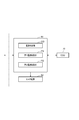
- FIG. 2 is a functional block diagram illustrating the SCU function.
- FIG. 3 is a block diagram illustrating a schematic configuration of an ECU employed in each embodiment.
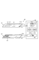
- FIG. 4 is a schematic configuration diagram of an element part and a heater part of the PM sensor.
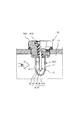
- FIG. 5 is a schematic cross-sectional view showing a state where a PM sensor is attached to the exhaust passage of the engine.
- FIG. 6 is a time chart of sensor output (6 (a) in the figure) and sensor temperature (6 (b) in the figure) during regeneration control of the PM sensor according to the first embodiment.
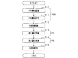
- FIG. 7 is a flowchart showing a processing procedure for performing regeneration control of the PM sensor according to the first embodiment.
- FIG. 8 is a time chart of sensor output (8 (a) in the figure) and sensor temperature (8 (b) in the figure) during regeneration control of the PM sensor according to the second embodiment.
- FIG. 9 is a flowchart illustrating a processing procedure for performing regeneration control of the PM sensor according to the second embodiment.
- FIG. 10 is a time chart of sensor output (10 (a) in the figure) and sensor temperature (10 (b) in the figure) during regeneration control of the PM sensor according to the third embodiment.
- FIG. 11 is a flowchart illustrating a processing procedure for performing regeneration control of the PM sensor according to the third embodiment.
- FIG. 12 is a flowchart illustrating a processing procedure for performing regeneration control of the PM sensor according to the fourth embodiment.
- PM detection device particulate matter detection device
- the engine system 10 includes an engine 20.
- the engine 20 (internal combustion engine) is, for example, a diesel engine.
- An intake passage 12 and an exhaust passage 13 are connected to the engine 20.
- An exhaust gas purification device 14 is attached to the exhaust passage 13.
- the exhaust purification device 14 is configured to remove harmful components from the exhaust discharged from the engine 20.
- the harmful components include nitrogen oxides, carbon compounds such as HC (Hydrocarbon) and CO (Carbon Monoxide) generated by unburned or incomplete combustion of fuel, PM, and the like.
- the exhaust gas purification device 14 is provided with a PM collection filter 15. Since the configuration of the exhaust purification device 14 is well known, a detailed description thereof will be omitted.
- the engine system 10 is provided with a temperature sensor 16 and a PM detection device 80.
- the temperature sensor 16 is disposed on the upstream side of the exhaust passage 13 relative to the exhaust purification device 14 and monitors the exhaust temperature.
- An ECU (Electrical Control Unit) 70 which will be described later, monitors the state of the exhaust purification device 14 and the PM collection filter 15 based on the exhaust temperature, and if the PM collection amount exceeds an allowable amount, the PM collection filter 15 Perform playback control.
- the PM detection device 80 includes a PM sensor 50, an SCU 60 (sensor control unit), and an ECU 70, and detects the amount of PM that has passed through the PM collection filter 15.
- PM is mainly composed of soot and soluble organic components (hereinafter referred to as SOF), and contains an ash component (hereinafter referred to as ash).
- Ash is generated by oxidation of metal components and the like contained in engine oil and fuel additives.
- ash is made of oxides such as phosphorus, sulfur and calcium.
- the soot that is the main component of PM is a conductive substance, while ash is an insulating substance.
- the PM sensor 50 is disposed on the downstream side of the exhaust passage 13 with respect to the exhaust purification device 14, and detects PM passing through the PM collection filter 15 and slipping downstream.
- the PM sensor 50 includes a sensor unit 40, a cover body 400, a cylindrical housing 500, and a cylindrical insulator 600.
- the tubular housing 500 is screwed to the passage wall of the exhaust passage 13, and the tubular insulator 600 is held inside the tubular housing 500.
- the cover body 400 has a hollow interior, is fixed to the lower end of the cylindrical housing 500, and protrudes into the exhaust passage 13.
- the upper half of the sensor unit 40 is inserted and fixed to the cylindrical insulator 600, and the lower half of the sensor unit 40 is located in the hollow portion of the cover body 400.
- Through holes 410 and 411 through which exhaust gas containing PM that has passed through the PM collection filter 15 flows in and out are formed in the bottom and sides of the cover body 400.
- the sensor unit 40 of the PM sensor 50 includes an element unit 41 and a heater unit 47.
- the element portion 41 is configured by forming a pair of comb-shaped electrodes 42 and 43 facing each other at a predetermined inter-electrode distance on one surface 45 a of the insulating substrate 45.
- the pair of electrodes are formed on the side surface of the element portion 41, but a pair of electrodes may be formed on the tip end surface of the element.
- the pair of electrodes 42 and 43 is connected to the control circuit 61 of the SCU 60.
- the insulating substrate 45 is formed of a ceramic material excellent in electrical insulation and heat resistance such as alumina, zirconia, beryllia, mullite, silicon nitride and the like in a flat plate shape by a known method such as a doctor blade method or a press forming method. ing.
- PM contained in the exhaust gas flowing from the through holes 410 and 411 adheres to the element portion 41. Since the main component of PM is a soot of conductive material, when PM adheres between the electrode 42 and the electrode 43, the electrical resistance between the electrodes decreases to a predetermined level and a current flows. That is, when PM adheres between the electrodes, the electrical characteristics of the element unit 41 change.
- the heater unit 47 is configured by forming the heater 44 on one surface 46 a of the insulating substrate 46 formed by the same method as the insulating substrate 45.
- the heater 44 is connected to the heater power supply 62 of the SCU 60.
- the heater unit 47 is disposed so that the heater 44 is directly below the electrodes 42 and 43, and efficiently heats the element unit 41 to a predetermined temperature.
- the insulating substrate 45 and the insulating substrate 46 may be integrated. That is, the heater 44 may be built in the insulating substrate 45 of the element unit 41, and the sensor unit 40 may be composed of only the element unit 41.
- the SCU 60 includes a control circuit 61 and a heater power supply 62.
- the heater power source 62 is a power source for power supplied to the heater 44.
- the control circuit 61 detects the current flowing through the electrodes 42 and 43 and transmits an electric signal corresponding to the detected current to the ECU 70.
- the control circuit 61 exchanges information with the ECU 70 as appropriate.
- the control circuit 61 controls the driving of the heater power source 62 to control the temperature of the heater 44, that is, the temperature of the element unit 41 heated by the heater 44. Specifically, as shown in FIG.
- the control circuit 61 stores a central processing unit (CPU) 61A that plays a central role in control processing, a ROM (not shown) that stores a predetermined program and functions as a non-transitional physical recording medium.
- the computer system includes a read-only memory (61B) and a RAM 61C (random-access memory).
- the CPU 61A executes a program stored in the ROM 61B in advance, thereby functionally realizing a temperature detection unit OD, a first temperature control unit P1, and a second temperature control unit P2, as shown in FIG.
- the RAM 61C is used as a memory for temporarily storing data when the CPU 61A executes processing.
- the ECU 70 is mainly composed of a microcomputer including a memory such as a CPU 70A, a ROM 70B, and a RAM 70C, an input / output interface (I / O) 70D, and the like, as shown in FIG.
- the ROM 70B functions as a non-transitional tangible recording medium as described above.
- the ECU 70 implements the function of the amount detection unit 70M that detects the amount of PM by executing the detection process given by the CPU 70A.
- the amount detection unit 70M detects the amount of PM based on the electrical characteristics of the element unit 41. Specifically, the amount detection unit 70M detects the amount of PM from the electric signal transmitted from the control circuit 61 and a correspondence map between the electric signal and the amount of PM.
- the ECU 70 also performs control of the engine 20 and regeneration control of the PM collection filter 15.
- the CPU 70A mounted on the ECU 70 and the CPU 60A mounted on the control circuit 61 of the SCU 60 cooperate with each other to perform processing for temperature control shown in
- the operation of the PM detection device 80 will be described.
- the ECU 70 monitors the detected amount of PM, and determines that the PM collection filter 15 is abnormal when it is clearly larger than normal.
- the PM collection filter 15 is normal, if the amount of accumulated PM in the element portion 41 exceeds a certain amount, the electrical resistance between the electrodes 42 and 43 becomes small, and the PM detection accuracy decreases. . Therefore, when PM accumulates to some extent on the element portion 41, it is desirable to perform sensor regeneration control that burns and removes the accumulated PM.
- the burning temperature of soot which is the main component of PM, is generally 600 ° C. or higher, and if heated to 750 ° C. or higher, soot can be completely burned and removed.
- the combustion temperature of SOF is generally 400 ° C. or higher.
- the melting point of ash is generally 900 ° C. or higher.
- the melting point may be lowered due to a so-called quantum size effect.
- a eutectic reaction may occur and the melting point may be lowered.
- the melting point of ash may be lowered to about 750 ° C., but is hardly lowered to 750 ° C. or lower.
- fusing point may fall by the same effect also about a cocoon and a soluble organic component.
- the present inventor has obtained the knowledge that when the element part 41 is heated to a temperature of, for example, 750 ° C. to 850 ° C. in order to completely burn the soot, the ash of the fine particles is melted and fused to the element part 41. . Since the PM sensor 50 detects the amount of PM based on the electrical characteristics of the element unit 41, when the ash of the insulating material is fused to the element unit 41, the sensitivity of the PM sensor 50 is reduced or lost.
- the soot does not completely burn, and there is a possibility that the unburned residue of the soot remains in the element unit 41.
- the element part 41 is heated to a temperature of 600 ° C. to 750 ° C., soot and SOF burn at a time, so that the ash does not fly well from the element part 41 and the ash may remain in the element part 41. is there. Therefore, in the first embodiment, in the sensor regeneration control, the temperature of the element unit 41 is heated in two stages.
- the control circuit 61 details of each function of the control circuit 61 will be described.
- the temperature detection unit OD detects the temperature of the element unit 41. Specifically, the temperature detection unit OD detects the temperature of the element unit 41 based on the electric resistance value of the heater 44. When the heater 44 is energized to generate heat, the electrical resistance value of the heater 44 changes. There is a certain relationship between the temperature of the heater 44 and the electrical resistance value of the heater 44. Therefore, the electrical resistance value of the heater 44 is measured by the SCU 60, and the temperature detection unit OD detects the temperature of the heater 44 from the measured value of the electrical resistance value and the correspondence relationship between the prepared temperature and the electrical resistance value. .
- the temperature of the heater 44 can be regarded as the temperature of the element unit 41.
- a temperature sensor 51 (temperature detection device) is provided in the element unit 41, and the temperature of the element unit 41 is detected based on the temperature detected by the temperature sensor 51. May be. By providing the temperature sensor 51 in the element unit 41, the temperature of the element unit 41 can be detected with high accuracy.
- the first temperature control unit P1 heats the element unit 41 to the first temperature range for the first period by the heater 44 based on the temperature detected by the temperature detection OD unit in the first period excluding the PM detection period. For example, the first temperature control unit P1 feeds back the detected temperature of the element unit 41 and controls the temperature of the element unit 41 to a target temperature within the first temperature range.
- the first temperature range is a temperature range where SOF burns and ash does not melt. Specifically, the first temperature range is 400 ° C. to 600 ° C.
- the PM detection period is a period in which PM is collected by attaching PM to the element unit 41.
- the 1st temperature control part P1 makes target temperature constant in a 1st temperature range, and controls it so that the temperature of the element part 41 may become fixed temperature, for example, 500 degreeC. Thereby, the element part 41 can be maintained at an appropriate temperature according to the situation in the first temperature range.
- the first temperature range of 400 ° C. to 600 ° C. is a temperature range lower than the melting point of ash even when the melting point of ash is low.
- the SOF burns before the soot burns, and the temperature of the element unit 41 may become higher than the target temperature due to the combustion heat of the SOF.
- the temperature of the element unit 41 Falls below the melting point of ash. Therefore, when the element unit 41 is heated to the first temperature range, the SOF is combusted and vaporized, and as the SOF is vaporized, the ash is released from the PM without being melted and flies from the element unit 41.
- the first temperature range is often higher than the exhaust temperature.
- the exhaust temperature of a diesel engine is about 400 ° C. Therefore, in the first temperature range, the thermophoretic force works from the element unit 41 toward the exhaust, and the ash moves away from the element unit 41. Therefore, by heating the element unit 41 to the first temperature range, the SOF is combusted and the ash is separated from the element unit 41.
- the electrical resistance between the electrodes 42 and 43 is increased by burning SOF.
- the output of the PM sensor 50 decreases.
- soot remains deposited between the electrodes 42 and 43, the output of the PM sensor 50 does not decrease to zero.
- the second temperature control unit P2 is a period excluding the PM period.
- the element unit 41 is heated to the second temperature range by the heater 44 based on the temperature detected by the temperature detection unit for the second period.
- the second temperature control unit P2 feeds back the detected temperature of the element unit 41 and controls the temperature of the element unit 41 to the target temperature in the second temperature range.
- the second temperature range is a temperature range higher than the first temperature range and where soot burns. Specifically, the second temperature range is 750 ° C. to 850 ° C.
- the second temperature control unit P2 like the first temperature control unit P1, makes the target temperature constant in the second temperature range, and the temperature of the element unit 41 is constant.
- the temperature is controlled to be 800 ° C.
- the second temperature range of 750 ° C. to 850 ° C. is a temperature range where soot is completely burned.
- first period and the second period are periods in which the exhaust passage 13 is dry, not a period in which condensed water exists in the exhaust passage 13 as in a cold start. Therefore, even if the element unit 41 is heated to the first temperature range and the second temperature range, there is no possibility that the element unit 41 is subject to water cracking. Whether or not the exhaust passage 13 is dry may be determined based on, for example, whether or not a predetermined time has elapsed since the start of the engine 20.
- the ECU 70 that is, the CPU 70A
- the SCU 60 that is, the CPU 60A
- step S10 detection of the amount of PM adhering to the element unit 41 is started while the heater 44 is turned off. Subsequently, in step S11, the detection of the amount of PM attached to the element unit 41 is completed with the heater 44 turned off (that is, the function of the amount detection unit 70M is exhibited).
- step S12 the heater 44 is turned on and regeneration control of the element unit 41 of the PM sensor 50 is started.
- step S13 the electric power of the heater 44 is controlled to heat the element unit 41 to the first temperature in the first temperature range for the first period.
- the element unit 41 is heated to 500 ° C. for 30 seconds.
- the SOF contained in the PM burns and the ash flies from the element portion 41.
- step S14 (corresponding to the second temperature control unit P2), the power of the heater 44 is controlled to heat the element unit 41 to the second temperature in the second temperature range for the second period.
- the element unit 41 is heated to 800 ° C. for 60 seconds.
- the soot contained in PM burns and PM deposited on the element part 41 is removed.
- step S15 the regeneration control is terminated and the heater 44 is turned off.
- One cycle of the durability test according to the first embodiment is a regeneration control of heating to 500 ° C. for 30 seconds + heating to 800 ° C. for 60 seconds ⁇ heater 44 is turned off and cooled for 15 seconds ⁇ heater 44 is turned off and PM detection is performed for 200 seconds ⁇ Driving for 300 seconds after PM detection ( ⁇ return to regeneration control).
- the durability test processing cycle related to the conventional regeneration control the regeneration control of the durability test processing cycle according to the first embodiment was heated at 800 ° C. for 60 seconds.
- PM was discharged from the engine 20 at an average concentration of 10 mg / m 3 and the number of endurance test cycles until PM detection could not be completed within 200 seconds was compared.
- the sensitivity of the PM sensor 50 decreased at the time when 110 cycles passed, and PM detection could not be completed within 200 seconds.
- the durability test according to the first embodiment the sensitivity of the PM sensor 50 is reduced when 160 cycles have elapsed, and PM detection cannot be completed within 200 seconds. That is, in the durability test according to the first embodiment, the temperature in the regeneration control is set to two stages, so that the fusion of the ash to the element portion 41 is suppressed, and the durability of the PM sensor 50 is improved.
- the SOF burns before the soot burns.
- the ash leaves the PM without melting and flies away from the element portion 41. Therefore, when the element part 41 is heated to the second temperature range, the ash is detached from the PM, so that the ash is fused to the element part 41 even if the element part 41 is heated to the second temperature range.
- the soot can be burned while suppressing the above.
- the first temperature range By setting the first temperature range to 400 ° C. to 600 ° C., even when the ash melting point is lowered, the first temperature range is lower than the ash melting point. Moreover, even if the temperature of the element part 41 becomes higher than target temperature with the combustion heat accompanying combustion of SOF while the 1st temperature range becomes low, it can be kept in temperature lower than melting
- first period and the second period are periods in which the exhaust passage 13 is dry, even if the element unit 41 is heated to the first temperature range and the second temperature range, Cracking can be prevented.
- the element portion 41 can be maintained at an appropriate temperature by controlling the temperature of the element portion 41 to a constant temperature.
- the temperature of the element unit 41 can be detected with high accuracy.
- the PM detection device 80 according to the second embodiment will be described with respect to differences from the PM detection device 80 according to the first embodiment.
- the PM detection device 80 according to the second embodiment is different from the first embodiment in the temperature control of the element unit 41 by the first temperature control unit P1 and the second temperature control unit P2.
- the first temperature control unit P1 performs control so that the target temperature is variable in the first temperature range and the temperature of the element unit 41 is variable during the first period. For example, the first temperature control unit P1 gradually increases the temperature of the element unit 41 from 400 ° C. to 600 ° C.
- the second temperature control unit P2 performs control so that the target temperature is variable in the second temperature range and the temperature of the element unit 41 is variable in the second period. For example, the second temperature control unit P2 gradually increases the temperature of the element unit 41 from 750 ° C. to 850 ° C.
- This processing procedure is repeatedly executed at predetermined intervals in cooperation between the ECU 70 and the SCU 60 until the engine 20 is stopped after the engine 20 is started and the exhaust passage 13 is dried.
- steps S20 to S22 the same processing as in steps S10 to S12 is performed.
- step S23 the electric power of the heater 44 is controlled to variably control the element unit 41 to a temperature within the first temperature range. For example, the element unit 41 is heated for 30 seconds while being changed at a temperature within 400 ° C. to 600 ° C.
- step S24 the electric power of the heater 44 is controlled to variably control the element unit 41 to a temperature within the second temperature range. For example, the element unit 41 is heated for 60 seconds while being changed at a temperature within 750 ° C. to 850 ° C.
- step S25 the regeneration control is terminated and the heater 44 is turned off. This process is complete
- the sensitivity of the PM sensor 50 decreased at the time when 180 cycles passed, and PM detection could not be completed within 200 seconds. That is, according to the second embodiment, the durability of the PM sensor 50 is further improved as compared with the first embodiment.
- the same effects as (1) to (3) and (5) to (6) of the first embodiment are obtained, and further, the ash is fused to the element portion 41. And the durability of the PM sensor 50 can be improved.
- the temperature control of the element unit 41 can be performed. Easy to do.
- the element unit 41 may be heated to a constant temperature as in the first embodiment.
- the PM detection device 80 according to the third embodiment will be described with respect to differences from the PM detection device 80 according to the first embodiment.
- the PM detection device 80 according to the first embodiment always starts the temperature control by the first temperature control unit P1 when the first period is reached.
- the PM detection apparatus 80 according to the third embodiment starts the temperature control by the first temperature control unit P1 only when the predetermined condition is satisfied when the first period is reached.
- the first temperature control unit P1 heats the element unit 41 to the first temperature range on the condition that the amount of PM detected by the amount detection unit 70M has reached a predetermined threshold value.
- the element unit 41 is heated to a two-stage temperature range. Further, when the PM deposition amount in the element unit 41 is less than the predetermined threshold, even if the ash is melted, the decrease in sensitivity of the PM sensor 50 is relatively small. For this purpose, the element unit 41 is heated at a constant temperature as in the conventional regeneration control.
- Whether or not the PM deposition amount in the element unit 41 has reached a predetermined threshold value is determined by whether or not the output current of the PM sensor 50 is equal to or greater than the threshold current.
- the threshold current is, for example, 15 ⁇ A.
- the output current of the PM sensor 50 is equal to or greater than the threshold current.
- the element unit 41 is heated at, for example, 500 ° C. for 30 seconds in the first period during regeneration control, and the element unit 41 is heated at, for example, 800 ° C. Heat for 60 seconds.
- the output current of the PM sensor 50 is less than the threshold current.
- the element unit 41 is heated at a constant temperature of, eg, 800 ° C. for 90 seconds during the regeneration control period.
- This processing procedure is repeatedly executed at predetermined intervals in cooperation between the ECU 70 and the SCU 60 until the engine 20 is stopped after the engine 20 is started and the exhaust passage 13 is dried.
- steps S30 and S31 the same processing as in steps S10 and S11 is performed.
- step S32 it is determined whether or not the detected value of the PM amount is equal to or greater than a threshold value. That is, it is determined whether the output current of the PM sensor 50 is equal to or greater than the threshold current.
- step S32 when the detected value of the PM amount is equal to or greater than the threshold value, regeneration control for heating the element unit 41 to a two-stage temperature range is performed in order to suppress the ash from being fused to the element unit 41.
- steps S33 to S35 processing similar to that in steps S12 to S14 is performed, and in step S38, the regeneration control is terminated, the heater 44 is turned off, and the present processing is terminated.
- Steps S32, S34, and S37 correspond to the first temperature control unit P1
- step S35 corresponds to the second temperature control unit P2.
- step S36 the heater 44 is turned on to start regeneration control, and in step S37, the element unit 41 is heated to a constant temperature.
- step S38 the regeneration control is finished, the heater 44 is turned off, and this process is finished.
- the same effects as in (1) to (6) of the first embodiment can be obtained, and the element unit 41 can be reduced to 2 on the condition that the detected amount of PM has reached the threshold value.
- Regeneration control for heating to a temperature range of steps is performed.
- step S33 to step S35 the temperature of the element unit 41 may be controlled to vary in the first temperature range and the second temperature range as in the second embodiment. Or you may control so that the temperature of the element part 41 may vary in any one of a 1st temperature range and a 2nd temperature range.
- the first temperature control unit P1 sets the temperature of the heater 44 based on the exhaust information.
- Exhaust information includes exhaust temperature, exhaust flow velocity, and the like.
- the exhaust temperature is detected by the temperature sensor 16.
- the exhaust flow velocity is calculated from the intake amount of the engine 20, the intake pressure, the cross-sectional area of the exhaust passage 13, and the like.
- the temperature of the element part 41 changes under the influence of the exhaust gas temperature, and the influence of the exhaust gas temperature increases as the exhaust gas flow velocity increases. For example, when the exhaust temperature is lower than the temperature of the element unit 41 and the exhaust flow rate is relatively large, the temperature of the element unit 41 tends to be lower than the temperature of the heater 44. Therefore, in this case, the first temperature control unit P1 sets the temperature of the heater 44 to be higher than the target temperature of the element unit 41.
- the second temperature control unit P2 also sets the temperature of the heater 44 based on the exhaust information, similarly to the first temperature control unit P1.
- This processing procedure is repeatedly executed at predetermined intervals in cooperation between the ECU 70 and the SCU 60 until the engine 20 is stopped after the engine 20 is started and the exhaust passage 13 is dried.
- steps S40 to S42 processing similar to that in steps S10 to S12 is performed.
- step S43 exhaust information such as exhaust temperature and exhaust flow velocity is acquired.
- step S44 based on the exhaust information acquired in step S43, the temperature of the heater 44 is set so that the element unit 41 is heated to the first temperature in the first temperature range, and the element unit 41 is set to the first temperature. Heat for a period.
- step S45 exhaust information is acquired.
- step S46 based on the exhaust information acquired in step S45, the temperature of the heater 44 is set so that the element unit 41 is heated to the second temperature in the second temperature range, and the element unit 41 is set to the second temperature. Heat for a period.
- step S47 the regeneration control is terminated and the heater 44 is turned off. This process is complete
- the same effects as in (1) to (6) of the first embodiment are obtained, and the temperature at which the element unit 41 is heated is set based on the exhaust information.
- the temperature of the element unit 41 can be controlled with high accuracy so as to become the target temperature. As a result, the fusion
- step S44 and step S46 you may control so that the temperature of the element part 41 may vary in a 1st temperature range and a 2nd temperature range like 2nd Embodiment. Or you may control so that the temperature of the element part 41 may vary in any one of a 1st temperature range and a 2nd temperature range.
- regeneration control for heating the element unit 41 to a two-stage temperature range may be performed on the condition that the detected amount of PM has reached the threshold value.
- the fourth embodiment may be implemented by appropriately combining the second embodiment and the third embodiment.
- the function of the control circuit 61 of the SCU 60 may be realized by the ECU 70, and the heater power supply 62 may be incorporated in the ECU 70. That is, the electrodes 42 and 43 and the heater 44 may be directly connected to the ECU 70, and the PM detection device 80 may be composed of the PM sensor 50 and the ECU 70. Even when the PM detection device 80 includes the SCU 60 and the ECU 70, the ECU 70 may realize a part of the functions of the control circuit 61, or the control circuit 61 may realize a part of the functions of the ECU 70. . Further, the ECU 70 may not control the engine 20.
- the application target of the PM detection device 80 is not limited to a diesel engine.
- the PM detection device 80 can also be applied to an engine that uses fuel such as gasoline, alcohol, and natural gas.
Landscapes
- Engineering & Computer Science (AREA)
- Chemical & Material Sciences (AREA)
- Combustion & Propulsion (AREA)
- Mechanical Engineering (AREA)
- General Engineering & Computer Science (AREA)
- Chemical Kinetics & Catalysis (AREA)
- Health & Medical Sciences (AREA)
- Toxicology (AREA)
- Dispersion Chemistry (AREA)
- Physics & Mathematics (AREA)
- Life Sciences & Earth Sciences (AREA)
- Analytical Chemistry (AREA)
- Biochemistry (AREA)
- General Health & Medical Sciences (AREA)
- General Physics & Mathematics (AREA)
- Immunology (AREA)
- Pathology (AREA)
- Processes For Solid Components From Exhaust (AREA)
- Exhaust Gas After Treatment (AREA)
Abstract
粒子状物質検出装置が提供される。この装置では、エンジン(20)の排気中に含まれるPMを付着させる素子部41と、素子部41を加熱するヒータ44と、素子部41の電気的特性に基づいてPMの量を検出する量検出部と、素子部41の温度を検出する温度検出部とを備える。この装置はさらに、第1温度制御部(70(P1))及び第2温度制御部(70(P2))を備える。第1温度制御部(70(P1))は、素子部41にPMを付着させる期間を除く第1期間において、検出された素子部41の温度に基づいて、ヒータ44により、素子部41を、PMに含まれる可溶性有機成分が燃焼し、且つPMに含まれる灰成分が融解しない第1温度域に加熱させる。第1期間は、素子部41にPMを付着させる期間を除く期間である。また、第2温度制御部(70(P2))は、第1の期間の後の第2期間において、検出された素子部41の温度に基づいて、ヒータ44により、素子部41を、第1温度域よりも高く且つPMに含まれる煤が燃焼する第2温度域に加熱させる。
Description
本発明は、粒子状物質を検出する粒子状物質検出装置に係り、特に、内燃機関の排気中に含まれる粒子状物質の量を検出する粒子状物質検出装置に関する。
従来、ディーゼルエンジン等の排気に含まれる粒子状物質(Particulate Matter)、以下「PM」という)を検出する粒子状物質センサ搭載した装置が知られている。この装置では、粒子状物質を検出した後、粒子状物質センサの素子を、PMを燃焼させる所定の温度域に制御して、素子部に堆積したPMを燃焼させて除去する構成のものが知られている(特許文献参照1)。堆積したPMを除去する制御を、再生制御という。再生制御を行うことにより、粒子状物質のセンサ素子を連続的に利用できる。
PMには、主体となる煤及び可溶性有機成分(SOF)だけでなく、エンジンオイルや燃料等に由来する灰成分も含まれる。灰成分は、硫酸カルシウムや硫酸マグネシウム等を成分とする絶縁性物質である。本発明者は、素子部の再生制御を実施する際に、素子部を煤が燃焼する温度域に制御すると、灰成分の粒径等によっては、灰成分が融けて素子部へ融着することがあるとの知見を得た。PMセンサは、素子部の電気的特性に基づいてPMの量を検出するため、絶縁性物質である灰成分が素子部へ融着すると、PMの検出機能が低下したり喪失したりする。
本発明は、上記実情に鑑み、灰成分の素子部への融着を抑制可能な粒子状物質検出装置を提供することを主たる目的とする。
本発明は、粒子状物質検出装置であって、内燃機関(20)の排気中に含まれる粒子状物質を付着させる素子部(41)と、前記素子部を加熱するヒータ(44)と、前記素子部の電気的特性に基づいて前記粒子状物質の量を検出する量検出部(70)と、前記素子部の温度を検出する温度検出部(60)と、前記素子部に前記粒子状物質を付着させる期間を除く第1期間において、前記温度検出部により検出された前記温度に基づいて、前記ヒータにより、前記素子部を、前記粒子状物質に含まれる可溶性有機成分が燃焼し、且つ前記粒子状物質に含まれる灰成分が融解しない第1温度域に加熱する第1温度制御部(70)と、前記素子部に前記粒子状物質を付着させる期間を除く期間であって、前記第1期間の後の第2期間において、前記温度検出部により検出された前記温度に基づいて、前記ヒータにより、前記素子部を、前記第1温度域よりも高く且つ前記粒子状物質に含まれる煤が燃焼する第2温度域に加熱する第2温度制御部(70)と、を備える。
本発明によれば、素子部に粒子状物質を付着させる期間を除く第1期間において、素子部は、粒子状物質に含まれる可溶性有機成分が燃焼し、且つ粒子状物質に含まれ灰成分が融解しない第1温度域に加熱される。その後、第2期間において、素子部は、第1温度域よりも高く且つ粒子状物質に含まれる煤が燃焼する第2温度域に加熱される。
一般に、素子部に付着した粒子状物質の検出が終わると、粒子状物質が燃焼されて除去され、素子部が再生される。ここで、発明者は、灰成分の粒径等によっては、素子部を粒子状物質の主成分である煤が燃焼する温度に加熱した場合、粒子状物質に含まれる灰成分が融解し、素子部に灰成分が融着するとの知見を得た。この点、素子部を第2温度域に加熱する前に第1温度域に加熱することにより、煤が燃焼する前に可溶性有機成分が燃焼して蒸気となる。そして、可溶性有機成分の気化に伴い、灰成分は融解しないままPMから離脱して素子部から飛んでいく。よって、素子部を第2温度域に加熱する際には、粒子状物質から灰成分が離脱しているため、素子部を第2温度域に加熱しても、灰成分の素子部への融着を抑制しつつ、煤を燃焼させることができる。また、第1温度域に加熱することにより、可溶性有機成分が燃焼する際の燃焼熱で素子部の温度が目標温度より高くなることがあるが、灰成分が融解する温度よりも低い温度に収まるため灰成分の素子部への融着を抑制することができる。
添付図面において:
図1は、本実施形態に係るエンジンシステムの概略構成図。
図2は、SCU機能を例示する機能ブロック図。
図3は、各実施形態で採用されているECUの概略構成を示すブロック図。
図4は、PMセンサの素子部及びヒータ部の概略構成図。
図5は、エンジンの排気通路にPMセンサを取り付けた状態を示す概略断面図。
図6は、第1実施形態に係るPMセンサの再生制御時におけるセンサ出力(同図の6(a))、及びセンサ温度(同図の6(b))のタイムチャート。
図7は、第1実施形態に係るPMセンサの再生制御を実施する処理手順を示すフローチャート。
図8は、第2実施形態に係るPMセンサの再生制御時におけるセンサ出力(同図の8(a))、及びセンサ温度(同図の8(b))のタイムチャート。
図9は、第2実施形態に係るPMセンサの再生制御を実施する処理手順を示すフローチャート。
図10は、第3実施形態に係るPMセンサの再生制御時におけるセンサ出力(同図の10(a))、及びセンサ温度(同図の10(b))のタイムチャート。
図11は、第3実施形態に係るPMセンサの再生制御を実施する処理手順を示すフローチャート。
図12は、第4実施形態に係るPMセンサの再生制御を実施する処理手順を示すフローチャート。
以下、粒子状物質検出装置(以下、PM検出装置という)を、車両に搭載されたエンジンシステムへ適用した各実施形態について、図面を参照しつつ説明する。なお、以下の各実施形態において、互いに同一もしくは均等である部分には、図中、同一符号を付しており、同一符号の部分についてはその説明を援用する。
(第1実施形態)
まず、第1実施形態に係るエンジンシステム10の構成について説明する。図1に示すように、エンジンシステム10は、エンジン20を備える。エンジン20(内燃機関)は、例えば、ディーゼルエンジンである。エンジン20には、吸気通路12と排気通路13とが接続されている。排気通路13には、排気浄化装置14が装着されている。排気浄化装置14は、エンジン20から排出された排気から有害成分を除去するように構成されている。有害成分は、窒素酸化物、燃料の未燃あるいは不完全燃焼によって生じたHC(Hydrocarbon)やCO(Carbon monoxide)等の炭素化合物、PM等である。特に、第1実施形態においては、排気浄化装置14には、PM捕集フィルタ15が設けられている。排気浄化装置14の構成については周知であるので、詳細な説明は省略する。
まず、第1実施形態に係るエンジンシステム10の構成について説明する。図1に示すように、エンジンシステム10は、エンジン20を備える。エンジン20(内燃機関)は、例えば、ディーゼルエンジンである。エンジン20には、吸気通路12と排気通路13とが接続されている。排気通路13には、排気浄化装置14が装着されている。排気浄化装置14は、エンジン20から排出された排気から有害成分を除去するように構成されている。有害成分は、窒素酸化物、燃料の未燃あるいは不完全燃焼によって生じたHC(Hydrocarbon)やCO(Carbon monoxide)等の炭素化合物、PM等である。特に、第1実施形態においては、排気浄化装置14には、PM捕集フィルタ15が設けられている。排気浄化装置14の構成については周知であるので、詳細な説明は省略する。
また、エンジンシステム10には、温度センサ16及びPM検出装置80が設けられている。温度センサ16は、排気浄化装置14よりも排気通路13の上流側に配設されており、排気温度を監視している。後述するECU(Electrical Control Unit)70は、排気温度に基づいて、排気浄化装置14やPM捕集フィルタ15の状態を監視し、PM捕集量が許容量を超えると、PM捕集フィルタ15の再生制御を行う。
PM検出装置80は、PMセンサ50、SCU60(センサコントロールユニット)、及びECU70を備え、PM捕集フィルタ15を通過したPMの量を検出する。PMは、煤や可溶性有機成分(Soluble Organic Fraction、以下SOFという)を主体とし、灰成分(以下、アッシュという)を含む。アッシュは、エンジンオイルや燃料添加剤に含まれる金属成分等が酸化して発生したもので、例えば、リン、硫黄、カルシウム等の酸化物からなる。PMの主成分である煤は導電性物質であるが、アッシュは絶縁性物質である。
PMセンサ50は、排気浄化装置14よりも排気通路13の下流側に配設されており、PM捕集フィルタ15を通過して下流側にすり抜けるPMを検出する。以下、PMセンサ50の構成について、図4及び図5を参照して説明する。PMセンサ50は、センサ部40、カバー体400、筒状ハウジング500、及び筒状インシュレータ600を備える。筒状ハウジング500は、排気通路13の通路壁に螺結され、筒状インシュレータ600は、筒状ハウジング500の内部に保持される。カバー体400は、内部が中空に形成されており、筒状ハウジング500の下端部に固定されて、排気通路13内に突出している。センサ部40の上半部は、筒状インシュレータ600に挿入固定され、センサ部40の下半部は、カバー体400の中空部分に位置している。カバー体400の底部及び側部には、PM捕集フィルタ15を通過したPMを含む排気が流出入するための通孔410,411が穿設されている。
PMセンサ50のセンサ部40は、素子部41とヒータ部47とから構成されている。素子部41は、絶縁基板45における一の表面45a上に、所定の電極間距離をおいて対向する櫛歯形状の一対の電極42,43が形成されて構成されている。図5では素子部41の側面部に一対の電極が形成されているが、素子先端面に一対の電極が形成されていてもよい。一対の電極42,43は、SCU60の制御回路61に接続されている。絶縁基板45は、アルミナ、ジルコニア、べリリア、ムライト、窒化珪素等の電気絶縁性及び熱耐性に優れたセラミックス材料を、ドクターブレード法、プレス形成法等の公知の手法により平板状にして形成されている。素子部41には、通孔410,411から流入した排気中に含まれるPMが付着する。PMの主成分は導電性物質の煤であるため、PMが電極42と電極43との間に付着すると、電極間の電気抵抗は所定の程度まで低下し、電流が流れる。すなわち、電極間にPMが付着すると、素子部41の電気的特性が変化する。
ヒータ部47は、絶縁基板45と同様の手法で形成された絶縁基板46の一の表面46a上に、ヒータ44が形成されて構成されている。ヒータ44は、SCU60のヒータ電源62に接続されている。ヒータ部47は、ヒータ44が電極42,43の直下になるように配置されて、素子部41を効率よく所定温度に加熱する。なお、絶縁基板45と絶縁基板46は一体化されていてもよい。すなわち、ヒータ44は、素子部41の絶縁基板45に内蔵されており、センサ部40が素子部41のみから構成されていてもよい。
SCU60は、制御回路61及びヒータ電源62を備える。ヒータ電源62は、ヒータ44に供給される電力の電源となる。制御回路61は、電極42,43を流れる電流を検出し、検出した電流に応じた電気信号をECU70へ送信する。制御回路61は、適宜ECU70と情報をやり取りする。また、制御回路61は、ヒータ電源62の駆動を制御して、ヒータ44の温度、すなわちヒータ44で加熱される素子部41の温度を制御する。詳しくは、制御回路61は、後述する図4に示す如く、制御処理の中心を担うCPU(central processing unit)61A、所定のプログラムなどを保存するとともに非遷移的実体的記録媒体として機能するROM(read-only memory)61B、及びRAM61C(random―access memory)を備えたコンピュータシステムとして構成されている。ROM61Bに予め格納されたプログラムをCPU61Aが実行することで、機能的に、図2に示すように、温度検出部OD、第1温度制御部P1、及び第2温度制御部P2を実現する。なお、RAM61Cは、CPU61Aが処理を実行するときにデータを一時保存するメモリとして使用される。
ECU70も制御回路61と同様に、図3に示す如く、CPU70A、ROM70B、RAM70Cなどのメモリ、並びに、入出力インターフェース(I/O)70D等を備えるマイクロコンピュータを主体として構成されている。ROM70Bは、前述と同様に、非遷移的実体的記録媒体として機能する。ECU70は、CPU70Aが与えられた検出処理を実行することで、PMの量を検出する量検出部70Mの機能を実現する。量検出部70Mは、素子部41の電気的特性に基づいてPMの量を検出する。詳しくは、量検出部70Mは、制御回路61から送信された電気信号と、この電気信号とPMの量との対応マップ等とから、PMの量を検出する。また、ECU70は、エンジン20の制御や、PM捕集フィルタ15の再生制御を実施する。
なお、ECU70に搭載したCPU70A及びSCU60の制御回路61に搭載したCPU60Aは互いに協働して、後述する図7の温度制御のための処理を行う。
なお、ECU70に搭載したCPU70A及びSCU60の制御回路61に搭載したCPU60Aは互いに協働して、後述する図7の温度制御のための処理を行う。
次に、PM検出装置80の作動について説明する。PM捕集フィルタ15に何らかの異常が生じて正常な捕集が困難になると、PM捕集フィルタ15の下流側に放出されるPMの量が急増する。ECU70は、検出したPMの量を監視し、正常時よりも明らかに多い場合には、PM捕集フィルタ15の異常を判定する。ただし、PM捕集フィルタ15が正常であっても、素子部41におけるPMの堆積量が一定量を超える場合には、電極42,43間の電気抵抗が小さくなり、PMの検出精度が低下する。そのため、素子部41にPMがある程度堆積した場合には、堆積したPMを燃焼させて除去するセンサ再生制御を実施することが望ましい。
ここで、PMの主成分である煤の燃焼温度は一般に600℃以上であり、750℃以上に加熱すれば、煤を完全に燃焼させて除去できる。また、SOFの燃焼温度は、一般に400℃以上である。
また、アッシュの融点は一般に900℃以上である。ただし、アッシュが直径数ナノメートル程度の微粒子になると、いわゆる量子サイズ効果により融点が低下することがある。さらに、複数種類のアッシュが混合すると、共晶反応が生じて融点が低下することがある。その結果、アッシュの融点は750℃程度まで低下することがあるが、750℃以下にまでには低下しにくい。また、煤や可溶性有機成分についても同様の効果により融点が低下することがある。
本発明者は、煤を完全に燃焼させるために、素子部41を、例えば750℃~850℃の温度に加熱すると、微粒子のアッシュが融解して素子部41に融着するとの知見を得た。PMセンサ50は、素子部41の電気的特性に基づいてPMの量を検出するため、絶縁性物質のアッシュが素子部41に融着すると、PMセンサ50の感度が低下又は喪失する。
一方、素子部41を600℃~750℃の温度に加熱した場合、煤が完全に燃焼せず、煤の燃え残りが素子部41に残るおそれがある。また、素子部41を600℃~750℃の温度に加熱した場合、煤とSOFが一度に燃焼するため、アッシュが素子部41から上手く飛んでいかず、アッシュが素子部41に残留するおそれがある。そこで、第1実施形態では、センサの再生制御において、素子部41の温度を2段階に分けて加熱する。以下、制御回路61の各機能について詳細を説明する。
温度検出部ODは、素子部41の温度を検出する。具体的には、温度検出部ODは、ヒータ44の電気抵抗値に基づいて、素子部41の温度を検出する。ヒータ44に通電して発熱させると、ヒータ44の電気抵抗値は変化する。ヒータ44の温度とヒータ44の電気抵抗値との間には一定の関係がある。よって、SCU60によりヒータ44の電気抵抗値を測定し、温度検出部ODは、電気抵抗値の測定値と、予め用意した温度と電気抵抗値との対応関係とから、ヒータ44の温度を検出する。ヒータ44の温度は、素子部41の温度とみなせる。
あるいは、図1、図4~5に破線で示すように、素子部41に温度センサ51(温度検出装置)を設け、温度センサ51により検出された温度に基づいて、素子部41の温度を検出してもよい。素子部41に温度センサ51を設けることにより、素子部41の温度を高精度に検出することができる。
第1温度制御部P1は、PM検出期間を除く第1期間において、温度検出OD部により検出された温度に基づいて、ヒータ44により、素子部41を第1温度域に第1期間加熱する。例えば、第1温度制御部P1は、検出された素子部41の温度をフィードバックして、素子部41の温度を第1温度域内の目標温度に制御する。第1温度域は、SOFが燃焼し且つアッシュが融解しない温度域である。具体的には、第1温度域は、400℃~600℃である。PM検出期間は、素子部41にPMを付着させてPMを収集する期間である。
そして、図6(b)に示すように、第1温度制御部P1は、第1温度域において目標温度を一定にし、素子部41の温度が一定の温度例えば500℃になるように制御する。これにより、素子部41を、第1温度域内の状況に応じた適切な温度に維持することができる。
第1温度域400℃~600℃は、アッシュの融点が低くなっている場合でも、アッシュの融点よりも低い温度域である。また、素子部41を第1温度域に加熱すると、煤が燃焼する前にSOFが燃焼し、SOFの燃焼熱で素子部41の温度が目標温度よりも高くなることがある。しかしながら、第1温度域の上限値とアッシュの融点の下限値との間に十分なマージンがあるため、燃焼熱で素子部41の温度が目標温度よりも高くなっても、素子部41の温度はアッシュの融点よりも低い温度に収まる。よって、素子部41を第1温度域に加熱すると、SOFが燃焼して気化するとともに、SOFの気化に伴い、アッシュが融解しないままPMから離脱して素子部41から飛んでいく。
また、第1温度域は、排気温度よりも高いことが多い。例えば、ディーゼルエンジンの排気温度は400℃程度である。よって、第1温度域では、素子部41から排気の方向へ熱泳動力が働き、アッシュは素子部41から遠ざかる。したがって、素子部41を第1温度域に加熱することにより、SOFは燃焼され、アッシュは素子部41から引き離される。
図6(a)に示すように、第1期間では、SOFが燃焼することにより、電極42,43間の電気抵抗が大きくなっている。それと同時に、PMセンサ50の出力は低下するが、煤が電極42,43間に堆積したままなので、PMセンサ50の出力はゼロまで低下していない。
第2温度制御部P2は、PM期間を除く期間である。それは、第1期間の後の第2期間において、温度検出部により検出された温度に基づいて、ヒータ44により、素子部41を第2温度域に第2期間加熱する。例えば、第2温度制御部P2は、検出された素子部41の温度をフィードバックして、素子部41の温度を第2温度域の目標温度に制御する。第2温度域は、第1温度域よりも高く且つ煤が燃焼する温度域である。具体的には、第2温度域は、750℃~850℃である。
そして、図6(b)に示すように、第2温度制御部P2は、第1温度制御部P1と同様に、第2温度域において目標温度を一定にし、素子部41の温度が一定の温度例えば800℃となるように制御する。
第2温度域750℃~850℃は、煤を完全に燃焼させる温度域である。素子部41を750℃~850℃に加熱することにより、素子部41に堆積した煤は完全に燃焼され、燃え残りがなくなる。また、第2期間に移行した際には、アッシュはPMから離脱しているため、素子部41を第2温度域に加熱しても、アッシュの素子部41への融着は抑制される。
図6(a)に示すように、第2期間では、煤が燃焼するため、電極42,43間の電気抵抗が更に大きくなって非導通状態となり、PMセンサ50の出力はゼロまで低下している。
また、第1期間及び第2期間は、冷間始動時のように排気通路13に凝縮水が存在する期間ではなく、排気通路13が乾燥している期間である。そのため、素子部41を第1温度域及び第2温度域に加熱しても、素子部41が被水割れするおそれがない。排気通路13が乾燥しているか否かは、例えば、エンジン20の始動から所定時間経過したか否かで判定すればよい。
次に、第1実施形態に係るPMセンサ50の再生制御を実施する処理手順について、図7のフローチャートを参照して説明する。本処理手順は、エンジン20が始動して排気通路13の乾燥が完了した後、エンジン20が停止するまでの間、ECU70(つまり、CPU70A)及びSCU60(つまり、CPU60A)が協働して所定間隔で繰り返し実行する。
まず、ステップS10において、ヒータ44をオフにしたまま、素子部41に付着するPMの量の検出を開始する。続いて、ステップS11において、ヒータ44をオフにしたまま、素子部41に付着するPMの量の検出を完了する(つまり、量検出部70Mの機能が発揮される)。
続いて、ステップS12において、ヒータ44をオンにして、PMセンサ50の素子部41の再生制御を開始する。まず、ステップS13(第1温度制御部P1に相当)において、ヒータ44の電力を制御して、素子部41を第1温度域内の第1温度に第1期間加熱する。例えば、素子部41を、500℃に30秒間加熱する。これにより、PMに含まれるSOFが燃焼するとともに、アッシュが素子部41から飛んでいく。
続いて、ステップS14(第2温度制御部P2に相当)において、ヒータ44の電力を制御して、素子部41を第2温度域内の第2温度に第2期間加熱する。例えば、素子部41を、800℃に60秒間加熱する。これにより、PMに含まれる煤が燃焼し、素子部41に堆積していたPMが除去される。続いて、ステップS15において、再生制御を終了し、ヒータ44をオフにする。
以上で本処理を終了する。次の処理サイクルでは、ステップS10の処理から再度開始する。
次に、第1実施形態に係るPMセンサ50の再生制御を実施した場合、及び従来の一定温度による再生制御を実施した場合において、PMセンサ50の耐久試験を行った結果について述べる。第1実施形態に係る耐久試験の1サイクルは、500℃に30秒間加熱+800℃に60秒間加熱の再生制御→ヒータ44をオフにして15秒間冷却→ヒータ44をオフにして200秒間PM検出→PM検出後300秒間走行(→再生制御に戻る)、とした。従来の再生制御に係る耐久試験の処理サイクルは、第1実施形態に係る耐久試験の処理サイクルの再生制御を、800℃で60秒間加熱とした。どちらの耐久試験においても、PMを10mg/m3の平均濃度でエンジン20から排出させ、PM検出が200秒以内に完了できなくなるまでの耐久試験のサイクルの数を比較した。
その結果、従来の再生制御に係る耐久試験では、110サイクルを経過した時点で、PMセンサ50の感度が低下し、PM検出が200秒以内に完了できなくなった。これに対して、第1実施形態に係る耐久試験では、160サイクルを経過した時点で、PMセンサ50の感度が低下し、PM検出が200秒以内に完了できなくなった。すなわち、第1実施形態に係る耐久試験では、再生制御における温度を2段階としたことにより、アッシュの素子部41への融着が抑制され、PMセンサ50の耐久性が向上している。
以上説明した第1実施形態によれば、以下の効果を奏する。
(1)素子部41を第2温度域に加熱する前に第1温度域に加熱することにより、煤が燃焼する前にSOFが燃焼する。そして、SOFの燃焼に伴い、アッシュは融解しないままPMから離脱して素子部41から飛んでいく。よって、素子部41を第2温度域に加熱する際には、PMからアッシュが離脱しているため、素子部41を第2温度域に加熱しても、アッシュの素子部41への融着を抑制しつつ、煤を燃焼させることができる。
(2)第1温度域を400℃~600℃にすることにより、アッシュの融点が低下している場合でも、第1温度域がアッシュの融点よりも低くなる。また、第1温度域が低くなるとともに、SOFの燃焼に伴う燃焼熱で素子部41の温度が目標温度よりも高くなっても、アッシュの融点より低い温度に収めることができる。さらに、熱泳動力により、アッシュを素子部41から遠ざけることができる。よって、第1温度域を400℃~600℃にすることにより、再生制御時におけるアッシュの融解を好適に抑制することができる。また、第2温度域を750℃~850℃にすることにより、第2期間において、煤を確実に燃焼させることができる。
(3)第1期間及び第2期間は、排気通路13が乾燥している期間であるため、素子部41を第1温度域及び第2温度域に加熱しても、素子部41の被水割れを防止することができる。
(4)第1温度域及び第2温度域において、素子部41の温度を一定の温度に制御することにより、適切な温度に素子部41を維持することができる。
(5)ヒータ44の温度とヒータ44の抵抗値との間には一定の関係があり、ヒータ44の温度は素子部41の温度とみなせる。よって、ヒータ44の抵抗値に基づいて、素子部41の温度を検出することができる。
(6)素子部41に温度センサ51を設けることにより、素子部41の温度を高精度に検出することができる。
(第2実施形態)
次に、第2実施形態に係るPM検出装置80について、第1実施形態に係るPM検出装置80と異なる点について説明する。第2実施形態に係るPM検出装置80は、第1温度制御部P1及び第2温度制御部P2による素子部41の温度制御が、第1実施形態と異なる。
次に、第2実施形態に係るPM検出装置80について、第1実施形態に係るPM検出装置80と異なる点について説明する。第2実施形態に係るPM検出装置80は、第1温度制御部P1及び第2温度制御部P2による素子部41の温度制御が、第1実施形態と異なる。
詳しくは、第1温度制御部P1は、図8(b)に示すように、第1期間に、第1温度域において目標温度を可変にし、素子部41の温度が可変するように制御する。例えば、第1温度制御部P1は、素子部41の温度を、400℃から600℃へ徐々に上昇させる。また、第2温度制御部P2は、図8(b)に示すように、第2期間に、第2温度域において目標温度を可変にし、素子部41の温度が可変するように制御する。例えば、第2温度制御部P2は、素子部41の温度を、750℃から850℃へ徐々に上昇させる。
図8(b)に示すように、第1期間に、素子部41の温度を400℃から600℃へ徐々に上昇させると、SOFの堆積量が徐々に減少し、図8(a)に示すように、PMセンサ50の出力は徐々に低下する。これにより、SOF燃焼時の燃焼熱による過加熱が緩和され、アッシュの素子部41への融着が第1実施形態よりも更に抑制される。そして、図8(b)に示すように、第2期間に、素子部41の温度を750℃から850℃へ徐々に上昇させると、第1実施形態よりも煤の堆積量が緩やかに減少する。これにより、煤の燃焼時の燃焼熱による過加熱が緩和され、アッシュの素子部41への融着が第1実施形態よりも更に抑制される。そして、PMが除去され、図8(a)に示すように、PMセンサ50の出力がゼロに低下する。
次に、第2実施形態に係るPMセンサ50の再生制御を実施する処理手順について、図9のフローチャートを参照して説明する。本処理手順は、エンジン20が始動して排気通路13の乾燥が完了した後、エンジン20が停止するまでの間、ECU70及びSCU60が協働して所定間隔で繰り返し実行する。
まず、ステップS20からステップS22において、ステップS10からステップS12と同様の処理を行う。
続いて、ステップS23において、ヒータ44の電力を制御して、素子部41を第1温度域内の温度に可変制御する。例えば、素子部41を、400℃~600℃内の温度で変化させながら、30秒間加熱する。続いて、ステップS24において、ヒータ44の電力を制御して、素子部41を第2温度域内の温度に可変制御する。例えば、素子部41を、750℃~850℃内の温度で変化させながら、60秒間加熱する。続いて、ステップS25において、再生制御を終了し、ヒータ44をオフにする。以上で本処理を終了する。
第2実施形態について、第1実施形態と同様の耐久試験を行った結果、180サイクルを経過した時点で、PMセンサ50の感度が低下し、PM検出が200秒以内に完了できなくなった。すなわち、第2実施形態によれば、第1実施形態よりも更にPMセンサ50の耐久性が向上する。
以上説明した第2実施形態によれば、第1実施形態の(1)~(3)及び(5)~(6)と同様の効果を奏するとともに、更に、アッシュの素子部41への融着を抑制し、PMセンサ50の耐久性を向上させることができる。また、第1温度域及び第2温度域において、素子部41の温度を可変に制御することにより、素子部41の温度が排気の影響を受けて可変しても、素子部41の温度制御がし易い。
(第2実施形態の変形例)
第1期間の第1温度域及び第2期間の第2温度域のうちの一方において、第1実施形態と同様に、素子部41を一定の温度に加熱するようにしてもよい。
第1期間の第1温度域及び第2期間の第2温度域のうちの一方において、第1実施形態と同様に、素子部41を一定の温度に加熱するようにしてもよい。
(第3実施形態)
次に、第3実施形態に係るPM検出装置80について、第1実施形態に係るPM検出装置80と異なる点について説明する。第1実施形態に係るPM検出装置80は、第1期間となった際に、常に第1温度制御部P1による温度制御を開始した。これに対して、第3実施形態に係るPM検出装置80は、第1期間となった際に、所定の条件を満たす場合に限って、第1温度制御部P1による温度制御を開始する。
次に、第3実施形態に係るPM検出装置80について、第1実施形態に係るPM検出装置80と異なる点について説明する。第1実施形態に係るPM検出装置80は、第1期間となった際に、常に第1温度制御部P1による温度制御を開始した。これに対して、第3実施形態に係るPM検出装置80は、第1期間となった際に、所定の条件を満たす場合に限って、第1温度制御部P1による温度制御を開始する。
詳しくは、第1温度制御部P1は、量検出部70Mにより検出されたPMの量が所定閾値に到達したことを条件として、素子部41を第1温度域に加熱する。素子部41におけるPMの堆積量が多いほど、PMに含まれるアッシュの量も多くなり、アッシュが融解した際におけるPMセンサ50の感度の低下が大きくなる。
よって、素子部41におけるPMの堆積量が所定閾値に到達した場合には、アッシュが融解した際に、PMセンサ50の感度の低下が比較的大きい。そのために、第1実施形態と同様に、再生制御において、素子部41を2段階の温度域に加熱する。また、素子部41におけるPMの堆積量が所定閾値未満である場合には、アッシュが融解したとしてもPMセンサ50の感度の低下が比較的小さい。そのために、従来の再生制御のように、素子部41を一定温度で加熱する。
素子部41におけるPMの堆積量が所定閾値に到達したか否かは、PMセンサ50の出力電流が、閾値電流以上か否かで判定する。閾値電流は、例えば15μAである。図10(a)に実線で示すように、PMの堆積量が所定閾値以上の場合には、PMセンサ50の出力電流は閾値電流以上となる。この場合、図10(b)に実線で示すように、再生制御時の第1期間において、例えば500℃で素子部41を30秒間加熱し、第2期間において、例えば800℃で素子部41を60秒間加熱する。図10(a)に破線で示すように、PMの堆積量が所定閾値未満の場合には、PMセンサ50の出力電流は閾値電流未満となる。この場合、図10(b)に破線で示すように、再生制御の期間中、素子部41を例えば800℃の一定温度で90秒間加熱する。
次に、第3実施形態に係るPMセンサ50の再生制御を実施する処理手順について、図11のフローチャートを参照して説明する。本処理手順は、エンジン20が始動して排気通路13の乾燥が完了した後、エンジン20が停止するまでの間、ECU70及びSCU60が協働して所定間隔で繰り返し実行する。
まず、ステップS30及びステップS31において、ステップS10及びステップS11と同様の処理を行う。
続いて、ステップS32において、PM量の検出値が閾値以上か否か判定する。すなわち、PMセンサ50の出力電流が閾値電流以上か否か判定する。ステップS32において、PM量の検出値が閾値以上の場合、アッシュの素子部41への融着を抑制するため、素子部41を2段階の温度域に加熱する再生制御を実施する。具体的には、ステップS33からステップS35において、ステップS12からステップS14と同様の処理を行い、ステップS38において、再生制御を終了してヒータ44をオフにし、本処理を終了する。なお、ステップS32,S34,及びS37が第1温度制御部P1に相当し、ステップS35が第2温度制御部P2に相当する。
一方、ステップS32において、PM量の検出値が閾値未満の場合、アッシュの素子部41への融着を抑制する必要がないと判断して、従来の再生制御を実施する。具体的には、ステップS36において、ヒータ44をオンにして再生制御を開始し、ステップS37において、素子部41を一定温度に加熱する。そして、ステップS38において、再生制御を終了してヒータ44をオフにし、本処理を終了する。
以上説明した第3実施形態によれば、第1実施形態の(1)~(6)と同様の効果を奏するとともに、PMの検出量が閾値に到達したことを条件として、素子部41を2段階の温度域に加熱する再生制御が実施される。これにより、アッシュの素子部41への融着により、PMセンサ50の感度の比較的大きな低下が懸念される場合に、アッシュの素子部41への抑制処理が実施される。よって、アッシュの素子部41への融着の抑制をより効果的に実施できる。
(第3実施形態の変形例)
ステップS33からステップS35において、第2実施形態のように、第1温度域及び第2温度域において素子部41の温度が可変するように制御してもよい。あるいは、第1温度域及び第2温度域のいずれか一方で、素子部41の温度が可変するように制御してもよい。
ステップS33からステップS35において、第2実施形態のように、第1温度域及び第2温度域において素子部41の温度が可変するように制御してもよい。あるいは、第1温度域及び第2温度域のいずれか一方で、素子部41の温度が可変するように制御してもよい。
(第4実施形態)
次に、第4実施形態に係るPM検出装置80について、第1実施形態に係るPM検出装置80と異なる点について説明する。素子部41の温度は、排気の影響を受けて変化する。そこで、第4実施形態では、第1温度制御部P1及び第2温度制御部P2は、エンジン20の排気の情報に基づいて、素子部41を加熱する温度を設定する。
次に、第4実施形態に係るPM検出装置80について、第1実施形態に係るPM検出装置80と異なる点について説明する。素子部41の温度は、排気の影響を受けて変化する。そこで、第4実施形態では、第1温度制御部P1及び第2温度制御部P2は、エンジン20の排気の情報に基づいて、素子部41を加熱する温度を設定する。
詳しくは、第1温度制御部P1は、排気の情報に基づいて、ヒータ44の温度を設定する。排気の情報は、排気温度や排気流速等である。排気温度は温度センサ16により検出される。排気流速は、エンジン20の吸気量、吸気圧、排気通路13の断面積等から算出される。素子部41の温度は、排気温度の影響を受けて変化し、排気流速が大きいほど排気温度の影響を大きく受ける。例えば、排気温度が素子部41の温度よりも低く、排気流速が比較的大きい場合は、素子部41の温度はヒータ44の温度よりも低くなりやすい。よって、この場合、第1温度制御部P1は、ヒータ44の温度を素子部41の目標温度よりも高めに設定する。
第2温度制御部P2も、第1温度制御部P1と同様に、排気の情報に基づいて、ヒータ44の温度を設定する。
次に、第4実施形態に係るPMセンサ50の再生制御を実施する処理手順について、図12のフローチャートを参照して説明する。本処理手順は、エンジン20が始動して排気通路13の乾燥が完了した後、エンジン20が停止するまでの間、ECU70及びSCU60が協働して所定間隔で繰り返し実行する。
まず、ステップS40~ステップS42において、ステップS10~ステップS12と同様の処理を行う。
続いて、ステップS43において、排気温度や排気流速等の排気情報を取得する。続いて、ステップS44において、ステップS43で取得した排気情報に基づいて、素子部41を第1温度域内の第1温度に加熱するように、ヒータ44の温度を設定し、素子部41を第1期間加熱する。
続いて、ステップS45において、排気情報を取得する。続いて、ステップS46において、ステップS45で取得した排気情報に基づいて、素子部41を第2温度域内の第2温度に加熱するように、ヒータ44の温度を設定し、素子部41を第2期間加熱する。
続いて、ステップS47において、再生制御を終了し、ヒータ44をオフにする。以上で本処理を終了する。
以上説明した第4実施形態によれば、第1実施形態の(1)~(6)と同様の効果を奏するとともに、排気の情報に基づいて、素子部41を加熱する温度を設定することにより、素子部41の温度が目標温度となるように精度良く制御することができる。ひいては、アッシュの素子部41への融着をより抑制することができる。
(第4実施形態の変形例)
・ステップS44及びステップS46において、第2実施形態のように、第1温度域及び第2温度域において素子部41の温度が可変するように制御してもよい。あるいは、第1温度域及び第2温度域のいずれか一方で、素子部41の温度が可変するように制御してもよい。
・ステップS44及びステップS46において、第2実施形態のように、第1温度域及び第2温度域において素子部41の温度が可変するように制御してもよい。あるいは、第1温度域及び第2温度域のいずれか一方で、素子部41の温度が可変するように制御してもよい。
・第3実施形態のように、PMの検出量が閾値に到達したことを条件として、素子部41を2段階の温度域に加熱する再生制御を実施してもよい。第4実施形態に、第2実施形態及び第3実施形態を適宜組み合わせて実施してもよい。
(他の実施形態)
・SCU60の制御回路61の機能はECU70が実現し、ヒータ電源62はECU70に組み込まれていてもよい。すなわち、電極42,43及びヒータ44はECU70に直接接続されており、PM検出装置80はPMセンサ50とECU70とから構成されていてもよい。また、PM検出装置80が、SCU60及びECU70を備える場合も、制御回路61の一部の機能をECU70が実現してもよいし、ECU70の一部の機能を制御回路61が実現してもよい。また、ECU70は、エンジン20の制御を実施なくてもよい。
・SCU60の制御回路61の機能はECU70が実現し、ヒータ電源62はECU70に組み込まれていてもよい。すなわち、電極42,43及びヒータ44はECU70に直接接続されており、PM検出装置80はPMセンサ50とECU70とから構成されていてもよい。また、PM検出装置80が、SCU60及びECU70を備える場合も、制御回路61の一部の機能をECU70が実現してもよいし、ECU70の一部の機能を制御回路61が実現してもよい。また、ECU70は、エンジン20の制御を実施なくてもよい。
・PM検出装置80の適用対象は、ディーゼルエンジンに限定されない。PM検出装置80は、ガソリン、アルコール、天然ガス等の燃料を用いるエンジンに対しても適用できる。
20…エンジン、41…素子部、44…ヒータ、60…SCU、70…ECU、80…PM検出装置。
Claims (12)
- 内燃機関(20)の排気中に含まれる粒子状物質を付着させる素子部(41)と、
前記素子部を加熱するヒータ(44)と、
前記素子部の電気的特性に基づいて前記粒子状物質の量を検出する量検出部(70M)と、
前記素子部の温度を検出する温度検出部(OD)と、
前記素子部に前記粒子状物質を付着させる期間を除く第1期間において、前記温度検出部により検出された前記温度に基づいて、前記ヒータにより、前記素子部を、前記粒子状物質に含まれる可溶性有機成分が燃焼し、且つ前記粒子状物質に含まれる灰成分が融解しない第1温度域に加熱する第1温度制御部(P1)と、
前記素子部に前記粒子状物質を付着させる期間を除く期間であって、前記第1期間の後の第2期間において、前記温度検出部により検出された前記温度に基づいて、前記ヒータにより、前記素子部を、前記第1温度域よりも高く且つ前記粒子状物質に含まれる煤が燃焼する第2温度域に加熱する第2温度制御部(P2)と、を備える、粒子状物質検出装置。 - 前記第1温度域は400℃~600℃であり、
前記第2温度域は750℃~850℃である請求項1に記載の粒子状物質検出装置。 - 前記第1温度制御部(P1)は、前記量検出部(70M))により検出された前記量が所定閾値に到達したか否かを判断する判断部(S32)を備え、
前記第1温度制御部(P1)は、この判断部(S32)が、前記量が前記所定閾値に到達したこと判断した場合に、前記素子部を前記第1温度域に加熱する請求項1又は2に記載の粒子状物質検出装置。 - 前記第1期間及び前記第2期間は、前記内燃機関の排気通路(13)が乾燥している期間である請求項1~3のいずれか1項に記載の粒子状物質検出装置。
- 前記第1温度制御部(P1)は、前記第1温度域において、前記素子部の温度を一定の温度になるように制御する請求項1~4のいずれか1項に記載の粒子状物質検出装置。
- 前記第1温度制御部(P1)は、前記第1温度域において、前記素子部の温度を可変するように制御する請求項1~4のいずれか1項に記載の粒子状物質検出装置。
- 前記第2温度制御部(P2)は、前記第2温度域において、前記素子部の温度を一定の温度になるように制御する請求項1~6のいずれか1項に記載の粒子状物質検出装置。
- 前記第2温度制御部(P2)は、前記第2温度域において、前記素子部の温度を可変するように制御する請求項1~6のいずれか1項に記載の粒子状物質検出装置。
- 前記第1温度制御部(P1)は、前記内燃機関の排気の情報に基づいて、前記ヒータの温度を設定する請求項1~8のいずれか1項に記載の粒子状物質検出装置。
- 前記第2温度制御部(P2)は、前記内燃機関の排気の情報に基づいて、前記ヒータの温度を設定する請求項1~9のいずれか1項に記載の粒子状物質検出装置。
- 前記温度検出部は、前記ヒータの抵抗値に基づいて、前記素子部の温度を検出する請求項1~10のいずれか1項に記載の粒子状物質検出装置。
- 前記素子部に設けられた温度検出装置(51)を備え、
前記温度検出部は、前記温度検出装置により検出された温度に基づいて、前記素子部の温度を検出する請求項1~11のいずれか1項に記載の粒子状物質検出装置。
Priority Applications (3)
| Application Number | Priority Date | Filing Date | Title |
|---|---|---|---|
| US15/769,801 US10487716B2 (en) | 2015-10-21 | 2016-10-21 | Particulate matter detection apparatus |
| CN201680061513.0A CN108138625B (zh) | 2015-10-21 | 2016-10-21 | 颗粒状物质检测装置 |
| DE112016004813.0T DE112016004813T5 (de) | 2015-10-21 | 2016-10-21 | Partikelerfassungsvorrichtung |
Applications Claiming Priority (2)
| Application Number | Priority Date | Filing Date | Title |
|---|---|---|---|
| JP2015207175A JP6358226B2 (ja) | 2015-10-21 | 2015-10-21 | 粒子状物質検出装置 |
| JP2015-207175 | 2015-10-21 |
Publications (1)
| Publication Number | Publication Date |
|---|---|
| WO2017069241A1 true WO2017069241A1 (ja) | 2017-04-27 |
Family
ID=58557110
Family Applications (1)
| Application Number | Title | Priority Date | Filing Date |
|---|---|---|---|
| PCT/JP2016/081276 Ceased WO2017069241A1 (ja) | 2015-10-21 | 2016-10-21 | 粒子状物質検出装置 |
Country Status (5)
| Country | Link |
|---|---|
| US (1) | US10487716B2 (ja) |
| JP (1) | JP6358226B2 (ja) |
| CN (1) | CN108138625B (ja) |
| DE (1) | DE112016004813T5 (ja) |
| WO (1) | WO2017069241A1 (ja) |
Families Citing this family (4)
| Publication number | Priority date | Publication date | Assignee | Title |
|---|---|---|---|---|
| JP7088056B2 (ja) * | 2019-02-04 | 2022-06-21 | 株式会社デンソー | 粒子状物質検出センサ |
| CN110095395A (zh) * | 2019-06-03 | 2019-08-06 | 深圳市森世泰科技有限公司 | 用于气体颗粒物浓度测量的芯片、传感器及测量方法 |
| JP7215388B2 (ja) * | 2019-10-02 | 2023-01-31 | 株式会社デンソー | 制御装置 |
| CN113618959B (zh) * | 2021-08-02 | 2023-05-09 | 界首市锦丰塑业有限公司 | 一种具备筛选检测功能的废旧塑料回收再生生产设备 |
Citations (3)
| Publication number | Priority date | Publication date | Assignee | Title |
|---|---|---|---|---|
| EP2354484A1 (fr) * | 2010-01-04 | 2011-08-10 | Peugeot Citroën Automobiles SA | Procédé de diagnostic fonctionnel d'un capteur de suie |
| JP2012012960A (ja) * | 2010-06-29 | 2012-01-19 | Nippon Soken Inc | 粒子状物質検出センサ |
| JP2014134129A (ja) * | 2013-01-09 | 2014-07-24 | Nippon Soken Inc | 粒子状物質検出装置 |
Family Cites Families (20)
| Publication number | Priority date | Publication date | Assignee | Title |
|---|---|---|---|---|
| JPS59197847A (ja) | 1983-04-25 | 1984-11-09 | Ngk Spark Plug Co Ltd | スモーク濃度センサ |
| JPH07332067A (ja) * | 1994-06-01 | 1995-12-19 | Toyota Motor Corp | パティキュレートフィルタの再生時期判断装置 |
| JP3757860B2 (ja) * | 2001-12-18 | 2006-03-22 | トヨタ自動車株式会社 | 内燃機関の排気浄化装置 |
| US20080265870A1 (en) * | 2007-04-27 | 2008-10-30 | Nair Balakrishnan G | Particulate Matter Sensor |
| JP2011080942A (ja) * | 2009-10-09 | 2011-04-21 | Nippon Soken Inc | パティキュレート検出センサ |
| US8230716B2 (en) * | 2009-11-09 | 2012-07-31 | Delphi Technologies, Inc. | Method and system for diagnostics of a particulate matter sensor |
| JP2012047722A (ja) * | 2010-07-26 | 2012-03-08 | Denso Corp | 粒子状物質検出センサとその異常判定方法 |
| DE102010038613A1 (de) * | 2010-07-29 | 2012-02-02 | Robert Bosch Gmbh | Verfahren zum Regenerieren eines Sensors |
| JP5348089B2 (ja) | 2010-08-06 | 2013-11-20 | 株式会社デンソー | センサ制御装置 |
| JP2012037369A (ja) | 2010-08-06 | 2012-02-23 | Denso Corp | センサ制御装置 |
| JP5531849B2 (ja) | 2010-08-06 | 2014-06-25 | 株式会社デンソー | センサ制御装置 |
| JP5387591B2 (ja) | 2011-01-25 | 2014-01-15 | 株式会社デンソー | 検出装置 |
| US9151204B2 (en) * | 2011-02-25 | 2015-10-06 | Toyota Jidosha Kabushiki Kaisha | Device for detecting particulate matter in exhaust gas |
| EP2740910B1 (en) * | 2011-08-04 | 2018-01-10 | Toyota Jidosha Kabushiki Kaisha | Device for controlling internal combustion engine |
| DE102012210525A1 (de) | 2012-06-21 | 2013-12-24 | Robert Bosch Gmbh | Verfahren zur Funktionskontrolle eines Sensors zur Detektion von Teilchen und Sensor zur Detektion von Teilchen |
| JP6361918B2 (ja) | 2014-08-07 | 2018-07-25 | 株式会社デンソー | フィルタの故障検出装置 |
| JP6426072B2 (ja) * | 2014-10-02 | 2018-11-21 | 株式会社Soken | フィルタの故障検出装置、粒子状物質検出装置 |
| US10107733B2 (en) * | 2014-11-04 | 2018-10-23 | Cummins Emission Solutions Inc. | System and method of sensor reconditioning in an exhaust aftertreatment system |
| JP2016170118A (ja) | 2015-03-13 | 2016-09-23 | 株式会社日本自動車部品総合研究所 | 粒子状物質検出システム |
| JP6501672B2 (ja) | 2015-08-20 | 2019-04-17 | 株式会社デンソー | 粒子状物質検出システム |
-
2015
- 2015-10-21 JP JP2015207175A patent/JP6358226B2/ja active Active
-
2016
- 2016-10-21 US US15/769,801 patent/US10487716B2/en active Active
- 2016-10-21 WO PCT/JP2016/081276 patent/WO2017069241A1/ja not_active Ceased
- 2016-10-21 CN CN201680061513.0A patent/CN108138625B/zh not_active Expired - Fee Related
- 2016-10-21 DE DE112016004813.0T patent/DE112016004813T5/de not_active Withdrawn
Patent Citations (3)
| Publication number | Priority date | Publication date | Assignee | Title |
|---|---|---|---|---|
| EP2354484A1 (fr) * | 2010-01-04 | 2011-08-10 | Peugeot Citroën Automobiles SA | Procédé de diagnostic fonctionnel d'un capteur de suie |
| JP2012012960A (ja) * | 2010-06-29 | 2012-01-19 | Nippon Soken Inc | 粒子状物質検出センサ |
| JP2014134129A (ja) * | 2013-01-09 | 2014-07-24 | Nippon Soken Inc | 粒子状物質検出装置 |
Also Published As
| Publication number | Publication date |
|---|---|
| US20180306087A1 (en) | 2018-10-25 |
| US10487716B2 (en) | 2019-11-26 |
| JP2017078373A (ja) | 2017-04-27 |
| CN108138625B (zh) | 2020-10-09 |
| CN108138625A (zh) | 2018-06-08 |
| DE112016004813T5 (de) | 2018-07-26 |
| JP6358226B2 (ja) | 2018-07-18 |
Similar Documents
| Publication | Publication Date | Title |
|---|---|---|
| JP5115873B2 (ja) | パティキュレートフィルタの故障検出装置 | |
| JP6207158B2 (ja) | 煤粒子センサシステム | |
| CN104641216B (zh) | 用于探测微粒的传感器的功能检验的方法和用于探测微粒的传感器 | |
| CN107076690B (zh) | 过滤器的故障检测装置、颗粒状物质检测装置 | |
| JP2012012960A (ja) | 粒子状物質検出センサ | |
| WO2017069241A1 (ja) | 粒子状物質検出装置 | |
| JP2009144577A (ja) | パティキュレートフィルタの故障判定装置 | |
| JP6172466B2 (ja) | フィルタの故障検出装置及び粒子状物質検出装置 | |
| JP2012047722A (ja) | 粒子状物質検出センサとその異常判定方法 | |
| JP6248964B2 (ja) | 粒子状物質検出装置 | |
| JP2010275977A (ja) | 粒子状物質検出手段の故障判定装置 | |
| US20130283887A1 (en) | Method for operating a soot sensor | |
| JP5561262B2 (ja) | 検出システム | |
| US20170199111A1 (en) | Method for operating a particle sensor | |
| JP2012083121A (ja) | 粒子状物質検出センサ | |
| WO2016147711A1 (ja) | 粒子状物質検出システム | |
| JP6481966B2 (ja) | 制御装置 | |
| JP6444063B2 (ja) | 粒子状物質検出装置及び粒子状物質検出方法 | |
| JP6421736B2 (ja) | 粒子状物質検出装置 | |
| JP2017040214A (ja) | 粒子状物質検出システム | |
| JP2014059218A (ja) | Pmセンサの異常検出装置および方法 | |
| JP2011089791A (ja) | 粒子状物質検出装置 | |
| JP2017096166A (ja) | 制御装置 | |
| JP6358851B2 (ja) | 粒子状物質検出装置及び粒子状物質検出方法 | |
| JP2017218993A (ja) | フィルタ再生制御装置 |
Legal Events
| Date | Code | Title | Description |
|---|---|---|---|
| 121 | Ep: the epo has been informed by wipo that ep was designated in this application |
Ref document number: 16857554 Country of ref document: EP Kind code of ref document: A1 |
|
| WWE | Wipo information: entry into national phase |
Ref document number: 15769801 Country of ref document: US |
|
| WWE | Wipo information: entry into national phase |
Ref document number: 112016004813 Country of ref document: DE |
|
| 122 | Ep: pct application non-entry in european phase |
Ref document number: 16857554 Country of ref document: EP Kind code of ref document: A1 |