WO2017069232A1 - 粒子状物質検出装置 - Google Patents
粒子状物質検出装置 Download PDFInfo
- Publication number
- WO2017069232A1 WO2017069232A1 PCT/JP2016/081241 JP2016081241W WO2017069232A1 WO 2017069232 A1 WO2017069232 A1 WO 2017069232A1 JP 2016081241 W JP2016081241 W JP 2016081241W WO 2017069232 A1 WO2017069232 A1 WO 2017069232A1
- Authority
- WO
- WIPO (PCT)
- Prior art keywords
- temperature
- particulate matter
- element unit
- heater
- period
- Prior art date
- Legal status (The legal status is an assumption and is not a legal conclusion. Google has not performed a legal analysis and makes no representation as to the accuracy of the status listed.)
- Ceased
Links
Images

Classifications
-
- F—MECHANICAL ENGINEERING; LIGHTING; HEATING; WEAPONS; BLASTING
- F01—MACHINES OR ENGINES IN GENERAL; ENGINE PLANTS IN GENERAL; STEAM ENGINES
- F01N—GAS-FLOW SILENCERS OR EXHAUST APPARATUS FOR MACHINES OR ENGINES IN GENERAL; GAS-FLOW SILENCERS OR EXHAUST APPARATUS FOR INTERNAL-COMBUSTION ENGINES
- F01N3/00—Exhaust or silencing apparatus having means for purifying, rendering innocuous, or otherwise treating exhaust
- F01N3/02—Exhaust or silencing apparatus having means for purifying, rendering innocuous, or otherwise treating exhaust for cooling, or for removing solid constituents of, exhaust
- F01N3/021—Exhaust or silencing apparatus having means for purifying, rendering innocuous, or otherwise treating exhaust for cooling, or for removing solid constituents of, exhaust by means of filters
- F01N3/023—Exhaust or silencing apparatus having means for purifying, rendering innocuous, or otherwise treating exhaust for cooling, or for removing solid constituents of, exhaust by means of filters using means for regenerating the filters, e.g. by burning trapped particles
-
- F—MECHANICAL ENGINEERING; LIGHTING; HEATING; WEAPONS; BLASTING
- F01—MACHINES OR ENGINES IN GENERAL; ENGINE PLANTS IN GENERAL; STEAM ENGINES
- F01N—GAS-FLOW SILENCERS OR EXHAUST APPARATUS FOR MACHINES OR ENGINES IN GENERAL; GAS-FLOW SILENCERS OR EXHAUST APPARATUS FOR INTERNAL-COMBUSTION ENGINES
- F01N11/00—Monitoring or diagnostic devices for exhaust-gas treatment apparatus
-
- F—MECHANICAL ENGINEERING; LIGHTING; HEATING; WEAPONS; BLASTING
- F01—MACHINES OR ENGINES IN GENERAL; ENGINE PLANTS IN GENERAL; STEAM ENGINES
- F01N—GAS-FLOW SILENCERS OR EXHAUST APPARATUS FOR MACHINES OR ENGINES IN GENERAL; GAS-FLOW SILENCERS OR EXHAUST APPARATUS FOR INTERNAL-COMBUSTION ENGINES
- F01N3/00—Exhaust or silencing apparatus having means for purifying, rendering innocuous, or otherwise treating exhaust
- F01N3/02—Exhaust or silencing apparatus having means for purifying, rendering innocuous, or otherwise treating exhaust for cooling, or for removing solid constituents of, exhaust
- F01N3/021—Exhaust or silencing apparatus having means for purifying, rendering innocuous, or otherwise treating exhaust for cooling, or for removing solid constituents of, exhaust by means of filters
- F01N3/023—Exhaust or silencing apparatus having means for purifying, rendering innocuous, or otherwise treating exhaust for cooling, or for removing solid constituents of, exhaust by means of filters using means for regenerating the filters, e.g. by burning trapped particles
- F01N3/027—Exhaust or silencing apparatus having means for purifying, rendering innocuous, or otherwise treating exhaust for cooling, or for removing solid constituents of, exhaust by means of filters using means for regenerating the filters, e.g. by burning trapped particles using electric or magnetic heating means
-
- F—MECHANICAL ENGINEERING; LIGHTING; HEATING; WEAPONS; BLASTING
- F01—MACHINES OR ENGINES IN GENERAL; ENGINE PLANTS IN GENERAL; STEAM ENGINES
- F01N—GAS-FLOW SILENCERS OR EXHAUST APPARATUS FOR MACHINES OR ENGINES IN GENERAL; GAS-FLOW SILENCERS OR EXHAUST APPARATUS FOR INTERNAL-COMBUSTION ENGINES
- F01N9/00—Electrical control of exhaust gas treating apparatus
- F01N9/002—Electrical control of exhaust gas treating apparatus of filter regeneration
-
- F—MECHANICAL ENGINEERING; LIGHTING; HEATING; WEAPONS; BLASTING
- F02—COMBUSTION ENGINES; HOT-GAS OR COMBUSTION-PRODUCT ENGINE PLANTS
- F02D—CONTROLLING COMBUSTION ENGINES
- F02D41/00—Electrical control of supply of combustible mixture or its constituents
- F02D41/02—Circuit arrangements for generating control signals
- F02D41/14—Introducing closed-loop corrections
- F02D41/1438—Introducing closed-loop corrections using means for determining characteristics of the combustion gases; Sensors therefor
- F02D41/1444—Introducing closed-loop corrections using means for determining characteristics of the combustion gases; Sensors therefor characterised by the characteristics of the combustion gases
- F02D41/1466—Introducing closed-loop corrections using means for determining characteristics of the combustion gases; Sensors therefor characterised by the characteristics of the combustion gases the characteristics being a soot concentration or content
-
- F—MECHANICAL ENGINEERING; LIGHTING; HEATING; WEAPONS; BLASTING
- F02—COMBUSTION ENGINES; HOT-GAS OR COMBUSTION-PRODUCT ENGINE PLANTS
- F02D—CONTROLLING COMBUSTION ENGINES
- F02D41/00—Electrical control of supply of combustible mixture or its constituents
- F02D41/02—Circuit arrangements for generating control signals
- F02D41/14—Introducing closed-loop corrections
- F02D41/1438—Introducing closed-loop corrections using means for determining characteristics of the combustion gases; Sensors therefor
- F02D41/1493—Details
- F02D41/1494—Control of sensor heater
-
- G—PHYSICS
- G01—MEASURING; TESTING
- G01N—INVESTIGATING OR ANALYSING MATERIALS BY DETERMINING THEIR CHEMICAL OR PHYSICAL PROPERTIES
- G01N15/00—Investigating characteristics of particles; Investigating permeability, pore-volume or surface-area of porous materials
- G01N15/06—Investigating concentration of particle suspensions
- G01N15/0606—Investigating concentration of particle suspensions by collecting particles on a support
-
- G—PHYSICS
- G01—MEASURING; TESTING
- G01N—INVESTIGATING OR ANALYSING MATERIALS BY DETERMINING THEIR CHEMICAL OR PHYSICAL PROPERTIES
- G01N15/00—Investigating characteristics of particles; Investigating permeability, pore-volume or surface-area of porous materials
- G01N15/06—Investigating concentration of particle suspensions
- G01N15/0656—Investigating concentration of particle suspensions using electric, e.g. electrostatic methods or magnetic methods
-
- G—PHYSICS
- G01—MEASURING; TESTING
- G01N—INVESTIGATING OR ANALYSING MATERIALS BY DETERMINING THEIR CHEMICAL OR PHYSICAL PROPERTIES
- G01N27/00—Investigating or analysing materials by the use of electric, electrochemical, or magnetic means
- G01N27/02—Investigating or analysing materials by the use of electric, electrochemical, or magnetic means by investigating impedance
- G01N27/04—Investigating or analysing materials by the use of electric, electrochemical, or magnetic means by investigating impedance by investigating resistance
-
- F—MECHANICAL ENGINEERING; LIGHTING; HEATING; WEAPONS; BLASTING
- F01—MACHINES OR ENGINES IN GENERAL; ENGINE PLANTS IN GENERAL; STEAM ENGINES
- F01N—GAS-FLOW SILENCERS OR EXHAUST APPARATUS FOR MACHINES OR ENGINES IN GENERAL; GAS-FLOW SILENCERS OR EXHAUST APPARATUS FOR INTERNAL-COMBUSTION ENGINES
- F01N2550/00—Monitoring or diagnosing the deterioration of exhaust systems
- F01N2550/04—Filtering activity of particulate filters
-
- F—MECHANICAL ENGINEERING; LIGHTING; HEATING; WEAPONS; BLASTING
- F01—MACHINES OR ENGINES IN GENERAL; ENGINE PLANTS IN GENERAL; STEAM ENGINES
- F01N—GAS-FLOW SILENCERS OR EXHAUST APPARATUS FOR MACHINES OR ENGINES IN GENERAL; GAS-FLOW SILENCERS OR EXHAUST APPARATUS FOR INTERNAL-COMBUSTION ENGINES
- F01N2560/00—Exhaust systems with means for detecting or measuring exhaust gas components or characteristics
- F01N2560/05—Exhaust systems with means for detecting or measuring exhaust gas components or characteristics the means being a particulate sensor
-
- F—MECHANICAL ENGINEERING; LIGHTING; HEATING; WEAPONS; BLASTING
- F01—MACHINES OR ENGINES IN GENERAL; ENGINE PLANTS IN GENERAL; STEAM ENGINES
- F01N—GAS-FLOW SILENCERS OR EXHAUST APPARATUS FOR MACHINES OR ENGINES IN GENERAL; GAS-FLOW SILENCERS OR EXHAUST APPARATUS FOR INTERNAL-COMBUSTION ENGINES
- F01N2560/00—Exhaust systems with means for detecting or measuring exhaust gas components or characteristics
- F01N2560/20—Sensor having heating means
-
- Y—GENERAL TAGGING OF NEW TECHNOLOGICAL DEVELOPMENTS; GENERAL TAGGING OF CROSS-SECTIONAL TECHNOLOGIES SPANNING OVER SEVERAL SECTIONS OF THE IPC; TECHNICAL SUBJECTS COVERED BY FORMER USPC CROSS-REFERENCE ART COLLECTIONS [XRACs] AND DIGESTS
- Y02—TECHNOLOGIES OR APPLICATIONS FOR MITIGATION OR ADAPTATION AGAINST CLIMATE CHANGE
- Y02T—CLIMATE CHANGE MITIGATION TECHNOLOGIES RELATED TO TRANSPORTATION
- Y02T10/00—Road transport of goods or passengers
- Y02T10/10—Internal combustion engine [ICE] based vehicles
- Y02T10/40—Engine management systems
Definitions
- the present invention relates to an apparatus for detecting particulate matter contained in exhaust gas from an internal combustion engine.
- particulate matter sensor that detects particulate matter in exhaust (Particulate Matter, hereinafter referred to as “PM”) and then burns and removes PM deposited on the element portion of the particulate matter sensor.
- PM particulate Matter
- the element part of the particulate matter sensor is controlled to a predetermined temperature range for burning PM.
- the particulate matter sensor described in Patent Document 1 maintains the element portion in the predetermined temperature range from when PM is burned and removed until the internal combustion engine stops. Therefore, it is possible to suppress PM from being deposited on the element portion after the PM is burned and removed. For this reason, the particulate matter sensor can start detection of PM without performing PM combustion at the next startup of the internal combustion engine.
- the particulate matter sensor described in Patent Document 1 is maintained in a predetermined temperature range where PM is combusted after detection of PM. For this reason, the thermal stress added to the element part of a particulate matter sensor increases, and there exists a possibility that durability of a particulate matter sensor may fall.
- the present invention has been made in view of such circumstances, and its main purpose is to achieve both suppression of thermal stress applied to the element portion of the particulate matter detection device and suppression of deposition of poisonous substances on the element portion. It is an object of the present invention to provide a particulate matter detection device that can perform the above-described process.
- the present invention is a particulate matter detection device including an element part, a heater, a detection part, and a control part.
- the element unit adheres particulate matter contained in the exhaust gas of the internal combustion engine.
- the heater heats the element portion.
- the detection unit detects the amount of the particulate matter based on the electrical characteristics of the element unit.
- the control unit controls the operation of the heater.
- the control unit operates the heater with a predetermined control amount set in advance in a predetermined period.
- the predetermined period excludes a period during which the particulate matter adheres to the element portion.
- the predetermined control amount is set in advance so that the temperature of the element unit is higher than the temperature of the exhaust and lower than a predetermined temperature at which the element unit is thermally deteriorated.
- the particulate matter (PM) contained in the exhaust gas of the internal combustion engine is adhered to the element portion. Since PM has a certain degree of conductivity, when PM adheres to the element portion, the electrical characteristics of the element portion change. Therefore, the amount of the particulate matter is detected by the detection unit based on the electrical characteristics of the element unit.
- a heater for heating the element unit is operated by a predetermined control amount set in advance in the predetermined period by the control unit. Since the heater is operated for a predetermined period excluding the period in which the particulate matter is adhered to the element portion, there is no problem in causing the particulate matter to adhere to the element portion.
- the predetermined control amount is set in advance so that the temperature of the element portion is lower than a predetermined temperature at which the element portion is thermally deteriorated. For this reason, even if the heater is operated with a predetermined control amount, thermal stress applied to the element portion can be suppressed. Further, the predetermined control amount is set in advance so that the temperature of the element portion is higher than the temperature of the exhaust. When fine particles are present in a field with a temperature gradient, the particles are subjected to thermophoretic force toward the low temperature side. For this reason, a thermophoretic force can be applied to the poisonous substance or PM in a direction away from the element part, and deposition of the poisonous substance on the element part can be suppressed. In addition, since the heater is operated with a predetermined control amount set in advance, it is not necessary to adjust the control amount by detecting the temperature of the element portion.
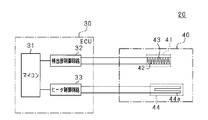
- the schematic diagram which shows the outline of an internal combustion engine system.
- the schematic diagram which shows the circuit structure of PM detection apparatus.
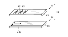
- the disassembled perspective view which shows the element part and heater of PM sensor.
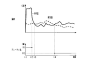
- the time chart which shows the change of element temperature and exhaust temperature.
- the present embodiment is embodied as an internal combustion engine system mounted on a vehicle.
- an internal combustion engine system 10 includes an internal combustion engine 11 that is a diesel engine.
- An intake passage 12 and an exhaust passage 13 are connected to the internal combustion engine 11.
- An exhaust gas purification device 14 is attached to the exhaust passage 13.
- the exhaust purification device 14 is configured to remove harmful components (nitrogen oxides, carbon compounds such as HC and CO, PM, etc. generated by unburned or incomplete combustion of fuel) from the exhaust discharged from the internal combustion engine 11.
- the exhaust purification device 14 is provided with a PM collection filter 15 (corresponding to a filter). Since the configuration of the exhaust purification device 14 is well known, the description thereof is omitted in this specification.
- the internal combustion engine system 10 is provided with a PM detection device 20 as a “particulate matter detection device”.
- the PM detection device 20 includes an ECU (Electric Control Unit) 30 and a PM sensor 40.
- the ECU 30 is configured to control the operation of the internal combustion engine 11 and its auxiliary machines and the operation as the PM detection device 20.
- the ECU 30 includes a microcomputer 31, a detection unit control circuit 32, and a heater control circuit 33.
- the microcomputer 31 includes a CPU (Central Processing Unit), a ROM (Read Only Memory), a RAM (Random Access Memory), a nonvolatile memory, and the like (not shown).
- the detection unit control circuit 32 is connected to an element unit 41 (including a pair of detection electrodes 42 and 43) provided in the PM sensor 40.
- the detection unit control circuit 32 is also connected to the microcomputer 31.
- the detection unit control circuit 32 includes a power supply circuit (not shown) that outputs a voltage applied between the detection electrodes 42 and 43 and a detection circuit (not shown) that detects the electrical characteristics of the element unit 41. Yes.
- the detection unit control circuit 32 causes the detection circuit to detect the electrical characteristics of the element unit 41 according to the adhesion state of the PM while a voltage is applied between the detection electrodes 42 and 43 by the power supply circuit.
- the detection circuit is configured to input the detected electrical characteristics to the microcomputer 31.
- the microcomputer 31 calculates the amount of PM adhering to the element unit 41 and, in turn, the amount of PM contained in the exhaust gas of the internal combustion engine 11 based on the detected electrical characteristics.
- the detection unit control circuit 32 and the microcomputer 31 constitute a detection unit.
- the heater control circuit 33 is connected to a heater 44 (including a heating wire 44a) provided in the PM sensor 40.
- the heater control circuit 33 is also connected to the microcomputer 31.
- the heater control circuit 33 includes a power supply circuit (not shown) and a drive circuit (not shown).
- the power supply circuit outputs a voltage applied to the heating wire 44a.
- the drive circuit changes the state in which the voltage of the power supply circuit is output to the heating wire 44a.
- the drive circuit changes a duty ratio that is a ratio of energizing the heating wire 44a in a predetermined period (pulse width modulation control).
- the microcomputer 31 controls the operation of the heater 44 according to the duty ratio commanded to the drive circuit.
- the heater control circuit 33 and the microcomputer 31 constitute a control unit.
- the PM sensor 40 includes the element unit 41 and the heater 44 as described above.
- the element portion 41 is mounted in the exhaust passage 13 so that the PM contained in the exhaust adheres when exposed to the exhaust.
- the element unit 41 includes an insulating substrate 45 and a pair of detection electrodes 42 and 43.
- the detection electrodes 42 and 43 are formed on the surface of the insulating substrate 45 by, for example, platinum. Although platinum has high heat resistance, it is known that oxidation and evaporation decrease under a high-temperature oxygen atmosphere. About the sample which comprised the detection electrodes 42 and 43 with the platinum electrode, the high temperature load test in air
- the insulating substrate 45 is made of ceramics or the like.
- the heater 44 is provided so as to burn and remove the PM adhering to the element unit 41 by generating heat by energization and heating the element unit 41.
- the heater 44 includes an insulating substrate 46 and a heating wire 44a.
- the heating wire 44a is formed on the surface of the insulating substrate 46 by, for example, platinum.
- the insulating substrate 46 is made of ceramics or the like.
- the PM sensor 40 is formed by stacking (bonding) the insulating substrate 45 and the insulating substrate 46 so that the element portion 41 and the heater 44 do not face each other.
- An element portion 41 is formed on the insulating substrate 45.
- a heater 44 is formed on the insulating substrate 46. Since the configuration of the PM sensor 40 is well known, further description is omitted in this specification.
- poisonous substances include iron oxide in the exhaust passage 13 and ash (hereinafter referred to as “ash”) remaining after burning the PM in the element portion 41.
- Ash is mainly composed of a metal salt (insulating substance) such as calcium sulfate or magnesium sulfate. Such components are derived from metallic elements such as calcium contained in the lubricating oil of the internal combustion engine 11 and sulfur contained in the fuel.
- the ECU 30 heats the element unit 41 with the heater 44 in a predetermined period excluding the collection period in which PM is adhered to the element unit 41.
- a thermophoretic force that moves the poisonous substance and PM away from the element portion 41 acts.
- Thermophoresis is a phenomenon in which particles are directed to the low temperature side when minute particles are present in a temperature gradient field. That is, when the temperature of the element unit 41 becomes higher than the temperature of the exhaust, a thermophoretic force in a direction away from the element unit 41 acts on the poisonous substance and PM.
- the detection electrodes 42 and 43 of the element unit 41 may be oxidized or reduced in evaporation as described above.
- the ECU 30 operates the heater 44 in a predetermined period excluding a period in which PM is adhered to the element unit 41.
- the predetermined control amount is set in advance so that the temperature of the element unit 41 is higher than the temperature of the exhaust gas and lower than a predetermined temperature (650 ° C.) at which the element unit 41 is thermally deteriorated.
- the duty ratio D commanded to the drive circuit of the heater control circuit 33 is set to a preset duty ratio D2 (predetermined duty ratio).
- the drive circuit of the heater control circuit 33 energizes the heating wire 44a of the heater 44 with a duty ratio D2.
- This duty ratio D2 is determined by adaptation for each vehicle on which the internal combustion engine 11 is mounted.
- the lower limit value that can be adopted as the duty ratio D2 is determined so that the temperature of the element unit 41 is higher than the temperature of the exhaust gas even in the operating state of the internal combustion engine 11 in which the temperature of the element unit 41 is most likely to decrease. .
- an operation state of the internal combustion engine 11 in which the temperature of the element portion 41 is most likely to decrease an operation state in which low-temperature exhaust flows at a high flow rate is assumed.
- the upper limit value that can be adopted as the duty ratio D2 is 650 ° C. (the temperature of the detection electrodes 42 and 43 of the element portion 41 causes thermal degradation even in the operating state of the internal combustion engine 11 in which the temperature of the element portion 41 is most likely to rise). It is determined to be lower than a predetermined temperature. As an operation state of the internal combustion engine 11 in which the temperature of the element portion 41 is most likely to rise, an operation state in which high-temperature exhaust flows at a high flow rate is assumed.
- the duty ratio D2 is set as a fixed value between the lower limit value and the upper limit value. When the heater 44 is operated at a preset duty ratio D2, the temperature of the element unit 41 changes according to the temperature of the exhaust.
- the duty ratio D2 is set in advance so that the difference between the temperature of the element portion 41 and the temperature of the exhaust gas is smaller than 100 ° C.
- the duty ratio D2 when the temperature of the exhaust gas temporarily rises or when the element unit 41 is rapidly cooled, the temperature of the element unit 41 may temporarily become lower than the temperature of the exhaust gas. In this case, the thermophoretic force cannot be applied to the poisonous substance or PM in the direction away from the element unit 41.
- the duty ratio D2 in order to completely prevent such a state, the duty ratio D2 must be set excessively high, and the temperature of the element portion 41 is likely to be higher than 650 ° C.
- the duty ratio D2 is set in advance so that the temperature of the element portion 41 becomes higher than the temperature of the exhaust gas in a period exceeding 80% in a predetermined period. This predetermined period is a period during which the heater 44 is operated at the duty ratio D2.
- the internal combustion engine 11 was operated in a steady state in the maximum rotation speed range. Then, a test was performed under a condition corresponding to 300,000 km of actual traveling of the vehicle by providing a period in which the temperature of the exhaust becomes higher than the temperature of the element unit 41 by stopping the heater 44. As a result, when the period during which the exhaust temperature is higher than the temperature of the element unit 41 is 80% or more with respect to the predetermined period, the sensitivity of the PM sensor 40 does not decrease, and 75%, 70%, 65% In this case, the sensitivity was reduced by 15%, 21% and 30%, respectively.
- a PM collection filter 15 is provided upstream of the element portion 41 in the exhaust passage 13 of the internal combustion engine 11. During the period in which the PM collected by the PM collection filter 15 is combusted, high-temperature exhaust gas flows to the element unit 41 and the temperature of the element unit 41 is likely to rise rapidly. Further, even during the rapid acceleration period of the internal combustion engine 11, the high-temperature exhaust gas flows to the element part 41 and the temperature of the element part 41 is likely to rise rapidly. Even in such a case, if the temperature of the element unit 41 is to be made higher than the temperature of the exhaust, the duty ratio D2 must be set excessively high. In such a case, there is a high possibility that the temperature of the element unit 41 is higher than 650 ° C. In this regard, the duty ratio D2 is such that the temperature of the exhaust gas can be higher than the temperature of the element unit 41 during the period in which the PM collected by the PM collection filter 15 is burned or during the rapid acceleration period of the internal combustion engine 11. Is set in advance.
- the duty ratio D2 is set so that the temperature of the exhaust gas becomes higher than the temperature of the element portion 41 in the period of 80% with respect to the period (predetermined period) in which the heater 44 is operated at the duty ratio D2. Is set in advance. In other words, the duty ratio D2 is set in advance so that the temperature of the exhaust gas becomes lower than the temperature of the element unit 41 in a period of 10% with respect to the predetermined period. At this time, the temperature of the element portion 41 is not higher than the exhaust temperature by 100 ° C. or more, and is 600 ° C. at the maximum.
- the PM amount is detected once by the PM detection device 20 from the start to the end of the operation of the internal combustion engine 11. Therefore, a predetermined period in which the element unit 41 is heated with the duty ratio D2 by the heater 44 is included in the period after the amount of PM is detected. Specifically, a period from the end of detection of the amount of PM to the stop of operation of the internal combustion engine 11 is set as the predetermined period.
- FIG. 4 is a time chart showing an aspect in which the temperature of the element unit 41 and the temperature of the exhaust gas change in the PM amount detection by the PM detection device 20.
- the ECU 30 starts control for burning PM adhering to the element unit 41 prior to detection of the PM amount.
- the duty ratio D commanded to the drive circuit of the heater control circuit 33 is set to a preset duty ratio D1 higher than the duty ratio D2.
- the drive circuit of the heater control circuit 33 energizes the heating wire 44a of the heater 44 with a duty ratio D1.
- the duty ratio D1 is a duty ratio that raises the temperature of the element portion 41 to a temperature at which PM can be combusted (for example, 600 ° C.), and is determined by adaptation for each vehicle on which the internal combustion engine 11 is mounted. Thereby, as shown by a solid line, the temperature of the element part 41 rises to approximately 600 ° C.
- Times t1 to t2 are a combustion period (PM sensor regeneration mode) in which PM adhering to the element unit 41 is combusted.
- the ECU 30 ends the control for burning the PM adhering to the element unit 41.
- the microcomputer 31 sets the duty ratio D commanded to the drive circuit of the heater control circuit 33 to 0%. Thereby, the temperature of the element part 41 falls.
- Time t2 to t3 is a cooling period (PM sensor cooling mode) in which the element unit 41 is cooled.
- the ECU 30 starts control for attaching PM to the element unit 41.
- the detection unit control circuit 32 may charge the PM passing through the vicinity of the detection electrodes 42 and 43 by applying a voltage between the detection electrodes 42 and 43 by the power supply circuit (electrostatic collection).
- the power supply circuit electrostatic collection
- adhesion of PM to the element unit 41 is promoted.
- the temperature of the exhaust gas varies according to the operating state of the internal combustion engine 11, and accordingly, the temperature of the element unit 41 varies at a temperature slightly lower than the temperature of the exhaust gas.
- Times t3 to t4 are a collection period (PM collection mode) in which PM is adhered to the element unit 41.
- the ECU 30 detects the amount of PM attached to the element unit 41.
- the detection unit control circuit 32 causes the detection circuit to detect a current value flowing between the detection electrodes 42 and 43 in a state where a voltage is applied between the detection electrodes 42 and 43 by the power supply circuit.
- the detection circuit inputs the detected current value to the microcomputer 31.
- the microcomputer 31 calculates the amount of PM attached to the element unit 41 based on the input current value.
- the microcomputer 31 includes a map that defines the relationship between the current value and the amount of PM during the PM collection period (time t3 to t4). This map can be set in advance based on experiments or the like.
- the microcomputer 31 refers to the map to calculate the amount of PM corresponding to the input current value, and thus calculates the amount of PM contained in the exhaust gas of the internal combustion engine 11.
- the ECU 30 executes control to suppress poisonous substances and PM from adhering to the element unit 41.
- the duty ratio D commanded to the drive circuit of the heater control circuit 33 is the duty ratio D2.
- the drive circuit of the heater control circuit 33 energizes the heating wire 44a of the heater 44 with a duty ratio D2.
- the temperature of the element part 41 shown as a continuous line is maintained in a slightly higher state than the temperature of the exhaust gas shown as a broken line.
- the temperature of the exhaust varies depending on the operating state of the internal combustion engine 11. For this reason, the temperature of the element part 41 fluctuates at a temperature slightly higher than the temperature of the exhaust gas according to the temperature of the exhaust gas.
- the embodiment described in detail above has the following advantages.
- the microcomputer 31 and the heater control circuit 33 (ECU 30) have a predetermined duty ratio D2 (predetermined control amount) in a predetermined period excluding the collection period (time t3 to t4) during which PM is adhered to the element unit 41.
- the heater 44 is operated.
- the heater 44 is operated for a predetermined period excluding the collection period during which PM is adhered to the element unit 41, so that it does not hinder the adhesion of PM to the element unit 41.
- the duty ratio D2 is set in advance so that the temperature of the element unit 41 is lower than 650 ° C. (predetermined temperature) at which the element unit 41 is thermally deteriorated. For this reason, even if the heater 44 is operated at the duty ratio D2, the thermal stress applied to the element portion 41 can be suppressed. Further, the duty ratio D2 is set in advance so that the temperature of the element unit 41 is higher than the temperature of the exhaust gas in a period of 10% with respect to the predetermined period. When fine particles are present in a field with a temperature gradient, the particles are subjected to thermophoretic force toward the low temperature side.
- thermophoretic force can be applied to poisonous substances (ash, iron oxide, etc.) and PM in a direction away from the element part 41, and deposition of poisonous substances on the element part 41 can be suppressed.
- the heater 44 is operated with a preset duty ratio D2, it is not necessary to detect the temperature of the element unit 41 and adjust the control amount.
- the duty ratio D2 is set in advance so that the difference between the temperature of the element unit 41 and the temperature of the exhaust is smaller than 100 ° C.
- the temperature of exhaust gas from a diesel engine rises up to 500 ° C. Therefore, even if the temperature of the exhaust gas fluctuates, the temperature of the element portion 41 can be suppressed from becoming higher than 600 ° C.
- the duty ratio D2 is set in advance so that the temperature of the element portion 41 becomes higher than the temperature of the exhaust gas in a period exceeding 80% in the predetermined period.
- This predetermined period is a period during which the heater 44 is operated at the duty ratio D2. Therefore, suppression of thermal stress applied to the element portion 41 and suppression of poisonous substance deposition on the element portion 41 can be balanced appropriately.
- the duty ratio D2 is set so that the temperature of the exhaust gas can be higher than the temperature of the element unit 41 during the period in which the PM collected by the PM collection filter 15 is burned or during the rapid acceleration period of the internal combustion engine 11. It is set in advance. Therefore, in such a case, it can be exceptionally allowed that the temperature of the element part 41 temporarily becomes lower than the temperature of the exhaust. Further, the duty ratio D2 can be prevented from being set too high.
- the predetermined period during which the heater 44 is operated at the duty ratio D2 is included in the period after the amount of PM is detected by the microcomputer 31 and the detection unit control circuit 32 (ECU 30). For this reason, it is possible to prevent the PM from adhering to the element portion 41 until the amount of PM is detected. Furthermore, after the amount of PM is detected, the deposition of poisonous substances on the element unit 41 can be suppressed. In particular, since the period from the end of detection of the amount of PM to the stop of operation of the internal combustion engine 11 is set as the predetermined period, the amount of poisonous substances adhering to the element unit 41 can be minimized.
- the temperature of the element portion 41 is made higher than the temperature of the exhaust.
- the temperature of the element unit 41 changes according to the temperature of the exhaust, the temperature of the element unit 41 can be lowered when the temperature of the exhaust is low. Therefore, compared to a configuration in which the temperature of the element unit 41 is maintained at a constant temperature higher than the temperature of the exhaust, it is possible to suppress the element unit 41 from being heated more than necessary, and thermal stress applied to the element unit 41 Can be suppressed.
- the predetermined period during which the heater 44 is operated at the duty ratio D2 is the period after the amount of PM is detected each time. It may be included.
- a water repellent period for repelling water adhering to the element part 41 due to the Leidenfrost phenomenon is provided before the combustion period (time t1 to t2) in which PM adhering to the element part 41 is burned. Also good.
- the heater 44 may be energized with a duty ratio D2 during the water repellent period (predetermined period). Thereby, adhesion of poisonous substances to the element portion 41 can be suppressed during the water repellent period.
- the operation period of the internal combustion engine 11 in which the state in which PM adheres to the element unit 41 becomes abnormal may be set as a predetermined period excluding the collection period in which PM is adhered to the element unit 41. And if the period when the state which PM adheres becomes abnormal is complete
- the heater 44 is operated at a duty ratio D2 in a predetermined period. Therefore, a thermophoretic force can be applied to the PM in addition to the poisoning substance in a direction away from the element unit 41, and PM deposition on the element unit 41 can be suppressed. As a result, PM can be attached to the element unit 41 in an appropriate period, and the accuracy of detecting the amount of PM can be improved. As a period in which the state in which PM adheres to the element unit 41 becomes abnormal, it is possible to employ the time when the internal combustion engine 11 is started, the time of acceleration / deceleration, or the like.
- the temperature of the element unit 41 may temporarily become higher than the temperature at which PM starts combustion (for example, 500 ° C.). In this case, there is a possibility that PM adhering to the element portion 41 may temporarily burn.
- the duty ratio D2 in order to completely prevent such a state, the duty ratio D2 must be set excessively low, and there is a high possibility that the temperature of the element portion 41 becomes lower than the temperature of the exhaust.
- the duty ratio D2 is set in advance so that the temperature of the element unit 41 becomes lower than the temperature at which PM starts combustion in a period exceeding 80% in a predetermined period. Good.
- This predetermined period is a period during which the heater 44 is operated at the duty ratio D2. According to such a configuration, it is possible to suppress abnormal accumulation of PM on the element unit 41 while suppressing PM adhering to the element unit 41 from burning before detection. In addition, even if the temperature of the element part 41 becomes temporarily higher than the temperature at which PM starts combustion, the PM does not stop burning immediately.
- the duty ratio D2 is determined so that the temperature of the element unit 41 is combusted during the period in which the PM collected by the PM collection filter 15 is combusted or during the rapid acceleration period of the internal combustion engine 11.
- the temperature is extremely low in a cold district or the like.
- the duty ratio D2 is not limited to a fixed value, and may be variable between a lower limit value and an upper limit value.
- the configuration for operating the heater 44 with a predetermined control amount set in advance is not limited to the configuration in which the heater 44 is energized with the duty ratio D2.
- a configuration in which the heater 44 is energized with a predetermined current value set in advance, a configuration in which the heater 44 is energized with a predetermined voltage value set in advance, or the like may be employed.
- the heater 44 may be operated with a predetermined control amount set in advance so that the temperature of the element unit 41 is higher than the temperature of the exhaust gas and lower than a predetermined temperature at which the element unit 41 is thermally deteriorated.
- the ECU 30 controls the heater 44 with a control amount that lowers the temperature of the element unit 41 rather than operating the heater 44 with a predetermined control amount when the temperature of the element unit 41 is higher than the temperature at which PM starts combustion. It is also possible to adopt a configuration that operates.
- the temperature of the element unit 41 can be estimated based on the operating state of the internal combustion engine 11, for example.
- As a control amount for decreasing the temperature of the element unit 41 for example, a control amount obtained by reducing a predetermined control amount by a certain amount can be employed. According to such a configuration, the PM adhering to the element unit 41 can be prevented from temporarily burning.
- a temperature sensor for detecting the temperature of the element unit 41 is provided in the internal combustion engine.
- the ECU 30 can employ the following configuration. That is, the ECU 30 can employ a configuration in which the heater 44 is operated with a control amount that lowers the temperature of the element unit 41, rather than the heater 44 is operated with a predetermined control amount. According to such a structure, it can suppress reliably that PM adhering to the element part 41 combusts temporarily.
- a thermistor or the like that detects the temperature of the element unit 41 can be employed. When the heating wire 44a of the heater 44 is energized to generate heat, the resistance value of the heating wire 44a changes.
- the temperature of the heating wire 44a corresponds to a temperature sensor.
- a predetermined control amount can also be adjusted so that the temperature of the element part 41 may become target temperature.
- a configuration in which the heater 44 is provided separately from the PM sensor 40 may be employed.
- the PM detection device may be constituted by a PM sensor module including the PM sensor 40 and a control unit of the PM sensor 40.
- an internal combustion engine that uses fuel such as gasoline, alcohol, natural gas, etc.
- it can be embodied as a device that detects PM contained in exhaust gas.
- the temperature of exhaust gas from a gasoline engine rises to a maximum of 800 ° C.
- the temperature of the exhaust gas flowing to the element unit 41 may be allowed to temporarily exceed 500 ° C. in a limited operation state of the gasoline engine (internal combustion engine).
Landscapes
- Engineering & Computer Science (AREA)
- Chemical & Material Sciences (AREA)
- Combustion & Propulsion (AREA)
- Mechanical Engineering (AREA)
- General Engineering & Computer Science (AREA)
- Pathology (AREA)
- General Health & Medical Sciences (AREA)
- Physics & Mathematics (AREA)
- Health & Medical Sciences (AREA)
- Life Sciences & Earth Sciences (AREA)
- Analytical Chemistry (AREA)
- Biochemistry (AREA)
- Immunology (AREA)
- General Physics & Mathematics (AREA)
- Dispersion Chemistry (AREA)
- Chemical Kinetics & Catalysis (AREA)
- Electrochemistry (AREA)
- Processes For Solid Components From Exhaust (AREA)
- Exhaust Gas After Treatment (AREA)
- Combined Controls Of Internal Combustion Engines (AREA)
Priority Applications (3)
| Application Number | Priority Date | Filing Date | Title |
|---|---|---|---|
| DE112016004828.9T DE112016004828T5 (de) | 2015-10-21 | 2016-10-21 | Partikelerfassungsvorrichtung |
| CN201680061495.6A CN108138620B (zh) | 2015-10-21 | 2016-10-21 | 颗粒状物质检测装置 |
| US15/769,794 US10648381B2 (en) | 2015-10-21 | 2016-10-21 | Particulate matter detecting device |
Applications Claiming Priority (2)
| Application Number | Priority Date | Filing Date | Title |
|---|---|---|---|
| JP2015-207174 | 2015-10-21 | ||
| JP2015207174A JP6421736B2 (ja) | 2015-10-21 | 2015-10-21 | 粒子状物質検出装置 |
Publications (1)
| Publication Number | Publication Date |
|---|---|
| WO2017069232A1 true WO2017069232A1 (ja) | 2017-04-27 |
Family
ID=58557103
Family Applications (1)
| Application Number | Title | Priority Date | Filing Date |
|---|---|---|---|
| PCT/JP2016/081241 Ceased WO2017069232A1 (ja) | 2015-10-21 | 2016-10-21 | 粒子状物質検出装置 |
Country Status (5)
| Country | Link |
|---|---|
| US (1) | US10648381B2 (enExample) |
| JP (1) | JP6421736B2 (enExample) |
| CN (1) | CN108138620B (enExample) |
| DE (1) | DE112016004828T5 (enExample) |
| WO (1) | WO2017069232A1 (enExample) |
Families Citing this family (1)
| Publication number | Priority date | Publication date | Assignee | Title |
|---|---|---|---|---|
| JP7215388B2 (ja) | 2019-10-02 | 2023-01-31 | 株式会社デンソー | 制御装置 |
Citations (6)
| Publication number | Priority date | Publication date | Assignee | Title |
|---|---|---|---|---|
| JPH08296427A (ja) * | 1995-04-25 | 1996-11-12 | Nippondenso Co Ltd | 排気微粒子浄化装置 |
| JP2011080942A (ja) * | 2009-10-09 | 2011-04-21 | Nippon Soken Inc | パティキュレート検出センサ |
| JP2012189049A (ja) * | 2011-03-14 | 2012-10-04 | Denso Corp | 粒子状物質検出装置及びパティキュレートフィルタの故障検出装置 |
| WO2013018224A1 (ja) * | 2011-08-04 | 2013-02-07 | トヨタ自動車株式会社 | 内燃機関の制御装置 |
| JP2013253794A (ja) * | 2012-06-05 | 2013-12-19 | Denso Corp | 粒子状物質検出システム |
| WO2016063491A1 (ja) * | 2014-10-24 | 2016-04-28 | 日本特殊陶業株式会社 | 粒子検知システム |
Family Cites Families (11)
| Publication number | Priority date | Publication date | Assignee | Title |
|---|---|---|---|---|
| WO2008134060A1 (en) * | 2007-04-27 | 2008-11-06 | Ceramatec, Inc. | Particulate matter sensor |
| JP4758488B2 (ja) * | 2009-02-16 | 2011-08-31 | 本田技研工業株式会社 | 粒子状物質検出装置 |
| JP5201194B2 (ja) * | 2010-10-28 | 2013-06-05 | 株式会社デンソー | 粒子状物質検出装置及び粒子状物質検出素子の製造方法 |
| JP5115873B2 (ja) | 2010-12-08 | 2013-01-09 | 株式会社デンソー | パティキュレートフィルタの故障検出装置 |
| WO2012124054A1 (ja) | 2011-03-15 | 2012-09-20 | トヨタ自動車株式会社 | 内燃機関の制御装置 |
| US8677803B2 (en) * | 2011-06-27 | 2014-03-25 | Delphi Technologies, Inc. | Particulate matter detection method for a particulate matter sensor |
| JP6361918B2 (ja) | 2014-08-07 | 2018-07-25 | 株式会社デンソー | フィルタの故障検出装置 |
| US9803524B2 (en) * | 2015-02-03 | 2017-10-31 | Ford Global Technologies, Llc | Methods and systems for increasing particulate matter deposition in an exhaust particulate matter sensor |
| US9846110B2 (en) * | 2015-06-02 | 2017-12-19 | GM Global Technology Operations LLC | Particulate matter sensor diagnostic system and method |
| US9964481B2 (en) * | 2015-09-04 | 2018-05-08 | Ford Global Technologies, Llc | Method and system for exhaust particulate matter sensing |
| US9605578B1 (en) * | 2015-12-02 | 2017-03-28 | Baohua Qi | Particulate matter sensing device for controlling and diagnosing diesel particulate filter systems |
-
2015
- 2015-10-21 JP JP2015207174A patent/JP6421736B2/ja active Active
-
2016
- 2016-10-21 DE DE112016004828.9T patent/DE112016004828T5/de not_active Withdrawn
- 2016-10-21 US US15/769,794 patent/US10648381B2/en active Active
- 2016-10-21 CN CN201680061495.6A patent/CN108138620B/zh not_active Expired - Fee Related
- 2016-10-21 WO PCT/JP2016/081241 patent/WO2017069232A1/ja not_active Ceased
Patent Citations (6)
| Publication number | Priority date | Publication date | Assignee | Title |
|---|---|---|---|---|
| JPH08296427A (ja) * | 1995-04-25 | 1996-11-12 | Nippondenso Co Ltd | 排気微粒子浄化装置 |
| JP2011080942A (ja) * | 2009-10-09 | 2011-04-21 | Nippon Soken Inc | パティキュレート検出センサ |
| JP2012189049A (ja) * | 2011-03-14 | 2012-10-04 | Denso Corp | 粒子状物質検出装置及びパティキュレートフィルタの故障検出装置 |
| WO2013018224A1 (ja) * | 2011-08-04 | 2013-02-07 | トヨタ自動車株式会社 | 内燃機関の制御装置 |
| JP2013253794A (ja) * | 2012-06-05 | 2013-12-19 | Denso Corp | 粒子状物質検出システム |
| WO2016063491A1 (ja) * | 2014-10-24 | 2016-04-28 | 日本特殊陶業株式会社 | 粒子検知システム |
Also Published As
| Publication number | Publication date |
|---|---|
| JP6421736B2 (ja) | 2018-11-14 |
| CN108138620A (zh) | 2018-06-08 |
| US20180313243A1 (en) | 2018-11-01 |
| JP2017078372A (ja) | 2017-04-27 |
| US10648381B2 (en) | 2020-05-12 |
| CN108138620B (zh) | 2021-01-26 |
| DE112016004828T5 (de) | 2018-07-26 |
Similar Documents
| Publication | Publication Date | Title |
|---|---|---|
| US8627645B2 (en) | Emission control with a particulate matter sensor | |
| US10590827B2 (en) | Method and system for reducing particulate emissions | |
| US20140292350A1 (en) | Failure detection apparatus for an electrically heated catalyst | |
| US20110314796A1 (en) | Particulate matter detection sensor and control device of controlling the same | |
| JP6361918B2 (ja) | フィルタの故障検出装置 | |
| US9200555B2 (en) | Control device for electrically heated catalyst | |
| US20130283887A1 (en) | Method for operating a soot sensor | |
| JPWO2012063303A1 (ja) | 内燃機関の粒子状物質検出装置 | |
| KR102340459B1 (ko) | 입자 센서의 작동 방법 | |
| JP6089945B2 (ja) | 排気浄化装置の制御装置 | |
| JP2016170118A (ja) | 粒子状物質検出システム | |
| CN108138625B (zh) | 颗粒状物质检测装置 | |
| JP6421736B2 (ja) | 粒子状物質検出装置 | |
| JP5768892B2 (ja) | 内燃機関の制御装置 | |
| JP2017096153A (ja) | 制御装置 | |
| JP5267676B2 (ja) | 内燃機関の排気浄化装置 | |
| JP6365501B2 (ja) | 粒子状物質検出装置 | |
| JP6505578B2 (ja) | フィルタの故障検出装置、粒子状物質検出装置 | |
| JP5858030B2 (ja) | 自己治癒性セラミック材料を含む排ガスセンサの制御装置 | |
| US9115618B2 (en) | Method for the regeneration of a carbon particulate filter | |
| JP2017150411A (ja) | 内燃機関の排気浄化システム | |
| US20190032588A1 (en) | Sensor control apparatus | |
| JP2007017398A (ja) | 空燃比センサの制御装置 | |
| CN105715394A (zh) | 用于运行动力设备的方法以及相应的动力设备 |
Legal Events
| Date | Code | Title | Description |
|---|---|---|---|
| 121 | Ep: the epo has been informed by wipo that ep was designated in this application |
Ref document number: 16857545 Country of ref document: EP Kind code of ref document: A1 |
|
| WWE | Wipo information: entry into national phase |
Ref document number: 15769794 Country of ref document: US |
|
| WWE | Wipo information: entry into national phase |
Ref document number: 112016004828 Country of ref document: DE |
|
| 122 | Ep: pct application non-entry in european phase |
Ref document number: 16857545 Country of ref document: EP Kind code of ref document: A1 |