WO2017068975A1 - 高圧燃料供給ポンプとその製造方法並びに2部材の結合方法 - Google Patents
高圧燃料供給ポンプとその製造方法並びに2部材の結合方法 Download PDFInfo
- Publication number
- WO2017068975A1 WO2017068975A1 PCT/JP2016/079568 JP2016079568W WO2017068975A1 WO 2017068975 A1 WO2017068975 A1 WO 2017068975A1 JP 2016079568 W JP2016079568 W JP 2016079568W WO 2017068975 A1 WO2017068975 A1 WO 2017068975A1
- Authority
- WO
- WIPO (PCT)
- Prior art keywords
- cylinder
- pressure fuel
- fuel supply
- supply pump
- pressurizing chamber
- Prior art date
- Legal status (The legal status is an assumption and is not a legal conclusion. Google has not performed a legal analysis and makes no representation as to the accuracy of the status listed.)
- Ceased
Links
Images


Classifications
-
- F—MECHANICAL ENGINEERING; LIGHTING; HEATING; WEAPONS; BLASTING
- F02—COMBUSTION ENGINES; HOT-GAS OR COMBUSTION-PRODUCT ENGINE PLANTS
- F02M—SUPPLYING COMBUSTION ENGINES IN GENERAL WITH COMBUSTIBLE MIXTURES OR CONSTITUENTS THEREOF
- F02M59/00—Pumps specially adapted for fuel-injection and not provided for in groups F02M39/00 -F02M57/00, e.g. rotary cylinder-block type of pumps
- F02M59/20—Varying fuel delivery in quantity or timing
- F02M59/24—Varying fuel delivery in quantity or timing with constant-length-stroke pistons having variable effective portion of stroke
- F02M59/26—Varying fuel delivery in quantity or timing with constant-length-stroke pistons having variable effective portion of stroke caused by movements of pistons relative to their cylinders
-
- F—MECHANICAL ENGINEERING; LIGHTING; HEATING; WEAPONS; BLASTING
- F02—COMBUSTION ENGINES; HOT-GAS OR COMBUSTION-PRODUCT ENGINE PLANTS
- F02M—SUPPLYING COMBUSTION ENGINES IN GENERAL WITH COMBUSTIBLE MIXTURES OR CONSTITUENTS THEREOF
- F02M59/00—Pumps specially adapted for fuel-injection and not provided for in groups F02M39/00 -F02M57/00, e.g. rotary cylinder-block type of pumps
- F02M59/44—Details, components parts, or accessories not provided for in, or of interest apart from, the apparatus of groups F02M59/02 - F02M59/42; Pumps having transducers, e.g. to measure displacement of pump rack or piston
- F02M59/442—Details, components parts, or accessories not provided for in, or of interest apart from, the apparatus of groups F02M59/02 - F02M59/42; Pumps having transducers, e.g. to measure displacement of pump rack or piston means preventing fuel leakage around pump plunger, e.g. fluid barriers
-
- F—MECHANICAL ENGINEERING; LIGHTING; HEATING; WEAPONS; BLASTING
- F02—COMBUSTION ENGINES; HOT-GAS OR COMBUSTION-PRODUCT ENGINE PLANTS
- F02M—SUPPLYING COMBUSTION ENGINES IN GENERAL WITH COMBUSTIBLE MIXTURES OR CONSTITUENTS THEREOF
- F02M59/00—Pumps specially adapted for fuel-injection and not provided for in groups F02M39/00 -F02M57/00, e.g. rotary cylinder-block type of pumps
- F02M59/44—Details, components parts, or accessories not provided for in, or of interest apart from, the apparatus of groups F02M59/02 - F02M59/42; Pumps having transducers, e.g. to measure displacement of pump rack or piston
- F02M59/48—Assembling; Disassembling; Replacing
- F02M59/485—Means for fixing delivery valve casing and barrel to each other or to pump casing
-
- F—MECHANICAL ENGINEERING; LIGHTING; HEATING; WEAPONS; BLASTING
- F04—POSITIVE - DISPLACEMENT MACHINES FOR LIQUIDS; PUMPS FOR LIQUIDS OR ELASTIC FLUIDS
- F04B—POSITIVE-DISPLACEMENT MACHINES FOR LIQUIDS; PUMPS
- F04B1/00—Multi-cylinder machines or pumps characterised by number or arrangement of cylinders
- F04B1/04—Multi-cylinder machines or pumps characterised by number or arrangement of cylinders having cylinders in star- or fan-arrangement
- F04B1/0404—Details or component parts
- F04B1/0426—Arrangements for pressing the pistons against the actuated cam; Arrangements for connecting the pistons to the actuated cam
-
- F—MECHANICAL ENGINEERING; LIGHTING; HEATING; WEAPONS; BLASTING
- F04—POSITIVE - DISPLACEMENT MACHINES FOR LIQUIDS; PUMPS FOR LIQUIDS OR ELASTIC FLUIDS
- F04B—POSITIVE-DISPLACEMENT MACHINES FOR LIQUIDS; PUMPS
- F04B1/00—Multi-cylinder machines or pumps characterised by number or arrangement of cylinders
- F04B1/04—Multi-cylinder machines or pumps characterised by number or arrangement of cylinders having cylinders in star- or fan-arrangement
- F04B1/0404—Details or component parts
- F04B1/0448—Sealing means, e.g. for shafts or housings
-
- F—MECHANICAL ENGINEERING; LIGHTING; HEATING; WEAPONS; BLASTING
- F04—POSITIVE - DISPLACEMENT MACHINES FOR LIQUIDS; PUMPS FOR LIQUIDS OR ELASTIC FLUIDS
- F04B—POSITIVE-DISPLACEMENT MACHINES FOR LIQUIDS; PUMPS
- F04B1/00—Multi-cylinder machines or pumps characterised by number or arrangement of cylinders
- F04B1/04—Multi-cylinder machines or pumps characterised by number or arrangement of cylinders having cylinders in star- or fan-arrangement
- F04B1/053—Multi-cylinder machines or pumps characterised by number or arrangement of cylinders having cylinders in star- or fan-arrangement with actuating or actuated elements at the inner ends of the cylinders
-
- F—MECHANICAL ENGINEERING; LIGHTING; HEATING; WEAPONS; BLASTING
- F04—POSITIVE - DISPLACEMENT MACHINES FOR LIQUIDS; PUMPS FOR LIQUIDS OR ELASTIC FLUIDS
- F04B—POSITIVE-DISPLACEMENT MACHINES FOR LIQUIDS; PUMPS
- F04B11/00—Equalisation of pulses, e.g. by use of air vessels; Counteracting cavitation
- F04B11/0008—Equalisation of pulses, e.g. by use of air vessels; Counteracting cavitation using accumulators
- F04B11/0016—Equalisation of pulses, e.g. by use of air vessels; Counteracting cavitation using accumulators with a fluid spring
-
- F—MECHANICAL ENGINEERING; LIGHTING; HEATING; WEAPONS; BLASTING
- F04—POSITIVE - DISPLACEMENT MACHINES FOR LIQUIDS; PUMPS FOR LIQUIDS OR ELASTIC FLUIDS
- F04B—POSITIVE-DISPLACEMENT MACHINES FOR LIQUIDS; PUMPS
- F04B53/00—Component parts, details or accessories not provided for in, or of interest apart from, groups F04B1/00 - F04B23/00 or F04B39/00 - F04B47/00
- F04B53/16—Casings; Cylinders; Cylinder liners or heads; Fluid connections
-
- F—MECHANICAL ENGINEERING; LIGHTING; HEATING; WEAPONS; BLASTING
- F04—POSITIVE - DISPLACEMENT MACHINES FOR LIQUIDS; PUMPS FOR LIQUIDS OR ELASTIC FLUIDS
- F04B—POSITIVE-DISPLACEMENT MACHINES FOR LIQUIDS; PUMPS
- F04B7/00—Piston machines or pumps characterised by having positively-driven valving
- F04B7/0076—Piston machines or pumps characterised by having positively-driven valving the members being actuated by electro-magnetic means
-
- F—MECHANICAL ENGINEERING; LIGHTING; HEATING; WEAPONS; BLASTING
- F04—POSITIVE - DISPLACEMENT MACHINES FOR LIQUIDS; PUMPS FOR LIQUIDS OR ELASTIC FLUIDS
- F04B—POSITIVE-DISPLACEMENT MACHINES FOR LIQUIDS; PUMPS
- F04B9/00—Piston machines or pumps characterised by the driving or driven means to or from their working members
- F04B9/02—Piston machines or pumps characterised by the driving or driven means to or from their working members the means being mechanical
- F04B9/04—Piston machines or pumps characterised by the driving or driven means to or from their working members the means being mechanical the means being cams, eccentrics or pin-and-slot mechanisms
- F04B9/042—Piston machines or pumps characterised by the driving or driven means to or from their working members the means being mechanical the means being cams, eccentrics or pin-and-slot mechanisms the means being cams
-
- F—MECHANICAL ENGINEERING; LIGHTING; HEATING; WEAPONS; BLASTING
- F02—COMBUSTION ENGINES; HOT-GAS OR COMBUSTION-PRODUCT ENGINE PLANTS
- F02M—SUPPLYING COMBUSTION ENGINES IN GENERAL WITH COMBUSTIBLE MIXTURES OR CONSTITUENTS THEREOF
- F02M2200/00—Details of fuel-injection apparatus, not otherwise provided for
- F02M2200/16—Sealing of fuel injection apparatus not otherwise provided for
-
- F—MECHANICAL ENGINEERING; LIGHTING; HEATING; WEAPONS; BLASTING
- F02—COMBUSTION ENGINES; HOT-GAS OR COMBUSTION-PRODUCT ENGINE PLANTS
- F02M—SUPPLYING COMBUSTION ENGINES IN GENERAL WITH COMBUSTIBLE MIXTURES OR CONSTITUENTS THEREOF
- F02M2200/00—Details of fuel-injection apparatus, not otherwise provided for
- F02M2200/80—Fuel injection apparatus manufacture, repair or assembly
- F02M2200/8015—Provisions for assembly of fuel injection apparatus in a certain orientation, e.g. markings, notches or specially shaped sleeves other than a clip
-
- F—MECHANICAL ENGINEERING; LIGHTING; HEATING; WEAPONS; BLASTING
- F02—COMBUSTION ENGINES; HOT-GAS OR COMBUSTION-PRODUCT ENGINE PLANTS
- F02M—SUPPLYING COMBUSTION ENGINES IN GENERAL WITH COMBUSTIBLE MIXTURES OR CONSTITUENTS THEREOF
- F02M2200/00—Details of fuel-injection apparatus, not otherwise provided for
- F02M2200/80—Fuel injection apparatus manufacture, repair or assembly
- F02M2200/8053—Fuel injection apparatus manufacture, repair or assembly involving mechanical deformation of the apparatus or parts thereof
Definitions
- the present invention relates to a high-pressure fuel supply pump, a manufacturing method thereof, and a two-member joining method.
- a high-pressure fuel supply pump for increasing the pressure of fuel is widely used in a type in which fuel is directly injected into the combustion chamber.
- a liner is fitted into a cylinder hole formed in the housing, and the liner is brought into metal contact with the housing by caulking load when caulking the periphery of the plug that closes the opening of the cylinder hole.
- a hydraulic pump of a hydraulic unit for a brake device in which an internal seal that seals the suction side and the discharge side of the pump is formed between liners.
- Patent Document 1 in order to cope with a higher fuel pressure, it is necessary to increase the screw tightening axial force and fix the cylinder to the pump body. As a result, the screw size is increased, and thus the pump body is large. This may lead to an increase in manufacturing cost and restrictions on attachment to an internal combustion engine, which may impair the product quality.
- the cylinder end face is brought into close contact with the pump body by the axial force of the screw as a sealing method between the cylinder and the pump body.
- this method however, deformation until the close contact cannot be made depending on the surface roughness of the contact face.
- a gap may remain, and further, depending on geometrical tolerances such as the perpendicularity of parts, shakiness of the threaded part, etc., the contact surface may cause contact and the sealability may not be maintained.
- the stress of the caulking load tends to concentrate on the stepped portion at the tip of the punch, and the material flows plastically to the inner diameter side of the plug (center side of the plug) by caulking, so the contact surface between the punch and the housing A bending force due to plastic flow friction is applied to the pressing surface of the punch, and the punch may be easily damaged from the stepped portion.
- a high-strength material having a tensile strength of about 1000 MPa is used as the housing material in order to cope with the high pressure of the fuel, the life of the punch may be significantly reduced even if a die steel punch is used. There is.
- the housing is pressurized and plastically flowed so as to be sheared in the axial direction of the cylinder hole, the plastic flow of the housing causes local slip from the corner of the pressurizing part outer diameter side toward the center.
- the caulked portion may be cracked due to a decrease in elongation due to higher strength of the material.
- a material with low strength such as an aluminum die-cast material, cracking is likely to occur from a local sliding portion, and the caulking portion may be broken.
- An object of the present invention is to provide a high-pressure fuel supply pump capable of fixing a cylinder to a pump body with a simple structure even at a high fuel pressure and having a good sealing property.
- a high pressure fuel comprising a pump body in which a pressurizing chamber is formed, and a cylinder that is inserted into a hole formed in the pump body and formed in a cylindrical shape.
- an end of the pump body opposite to the pressurizing chamber is formed from the outer peripheral side to the inner peripheral side with respect to the inner peripheral surface facing the outer peripheral surface of the cylinder, and the cylinder side A protruding portion protruding to the opposite side of the pressurizing chamber with respect to the flat portion of the end portion of the pump body, and the protruding portion connects the cylinder to the pressurizing chamber. And is formed so as to be supported from the opposite side.
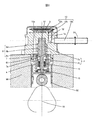
- FIG. 1 is an overall longitudinal sectional view of a high-pressure fuel supply pump according to a first embodiment in which the present invention is implemented.
- FIG. 5 is an overall longitudinal sectional view of another angle of the high-pressure fuel supply pump according to the first embodiment in which the present invention is implemented, and shows a sectional view at the center of the suction joint axis.
- 1 is an overall cross-sectional view of a high-pressure fuel supply pump according to a first embodiment in which the present invention is implemented, and shows a cross-sectional view at the center of an intake fuel discharge port shaft.
- Overall system configuration diagram The convex part shape which has three discontinuous parts is shown. The other shape of a convex part is shown. The state before caulking the cylinder to the pump body is shown.
- the state after caulking the cylinder to the pump body is shown.
- the detailed shape of an annular protrusion is shown.
- the detailed shape of a cylinder shoulder part is shown.
- the state before caulking of another cylinder shape is shown.
- the state after caulking of another cylinder shape is shown.
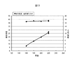
- the relationship between load, cylinder coupling strength and residual deflection is shown.
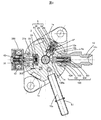
- FIG. 4 shows an overall configuration diagram of a high-pressure fuel supply system to which a high-pressure fuel supply pump (hereinafter referred to as a high-pressure pump) of this embodiment is applied.
- a portion surrounded by a broken line indicates a high-pressure pump main body, and a mechanism and components shown in the broken line indicate that the high-pressure pump main body 1 is integrally incorporated.
- Fuel in the fuel tank 20 is pumped up by a feed pump 21 based on a signal from an engine control unit 27 (hereinafter referred to as ECU). This fuel is pressurized to an appropriate feed pressure and sent to the low-pressure fuel inlet 10a of the high-pressure fuel supply pump through the suction pipe 28.
- ECU engine control unit 27
- the fuel that has passed through the suction joint 51 from the low-pressure fuel suction port 10a reaches the suction port 31b of the electromagnetic suction valve mechanism 300 constituting the variable capacity mechanism via the pressure pulsation reducing mechanism 9 and the suction passage 10d.
- the fuel that has flowed into the electromagnetic suction valve mechanism 300 passes through the suction valve 30 and flows into the pressurizing chamber 11.
- the reciprocating power is applied to the plunger 2 by the cam mechanism 93 of the engine.
- the reciprocating motion of the plunger 2 sucks fuel from the suction valve 30 during the downward stroke of the plunger 2 and pressurizes the fuel during the upward stroke.
- the discharge valve mechanism 8 the fuel is pumped to the common rail 23 to which the pressure sensor 26 is attached.
- the injector 24 injects fuel into the engine based on a signal from the ECU 27.
- the high-pressure fuel supply pump discharges the fuel flow rate of the desired supply fuel by a signal from the ECU 27 to the electromagnetic intake valve mechanism 300.
- a required amount of the fuel guided to the suction joint 51 is pressurized to a high pressure by the reciprocating motion of the plunger 2 in the pressurizing chamber 11 of the pump body 1 and is pumped to the common rail 23 from the fuel discharge port 12c.
- the common rail 23 is provided with a direct injection injector 24 (so-called direct injection injector) and a pressure sensor 26.
- the direct injection injectors 24 are mounted according to the number of cylinders of the internal combustion engine, and are opened and closed according to the control signal of the ECU 27 to inject fuel into the cylinders.
- the relief valve 101 opens when the differential pressure between the fuel discharge port 12c and the pressurizing chamber 11 exceeds the valve opening pressure of the relief valve mechanism 100.
- the fuel having an abnormally high pressure passes through the relief valve mechanism and returns to the pressurizing chamber 11 from the relief passage 100a, and the high-pressure section piping such as the common rail 23 is protected.
- the present embodiment is a high-pressure fuel supply pump applied to a so-called direct injection engine system in which the injector 24 directly injects fuel into the cylinder cylinder of the engine.
- FIG. 1 is an overall longitudinal sectional view of the high-pressure fuel supply pump of the present embodiment
- FIG. 2 is an overall longitudinal sectional view of another angle of the high-pressure fuel supply pump of the present embodiment, showing a sectional view at the center of the suction joint axis
- FIG. 3 is an overall cross-sectional view of the high-pressure fuel supply pump of this embodiment, and shows a cross-sectional view at the center of the fuel intake / discharge port axis.
- the high-pressure fuel supply pump of the present embodiment uses a mounting flange 1e provided on the pump body 1a, is in close contact with the high-pressure fuel supply pump mounting portion 90 of the internal combustion engine, and is fixed with a plurality of bolts.
- O-ring 61 is fitted into the pump body 1a for sealing between the high pressure fuel supply pump mounting portion 90 and the pump body 1a, thereby preventing the engine oil from leaking to the outside.
- the cylinder 6 which guides the reciprocating motion of the plunger 2 and forms the pressurizing chamber 11 together with the pump body 1a is attached to the pump body 1a.
- a tappet 92 that converts the rotational movement of the cam 93 attached to the camshaft of the internal combustion engine into a vertical movement and transmits it to the plunger 2.
- the plunger 2 is pressure-bonded to the tappet 92 by the spring 4 through the retainer 15. Thereby, the plunger 2 can be reciprocated up and down with the rotational movement of the cam 93.
- the plunger seal 13 held at the lower end on the inner periphery of the seal holder 7 is installed in a state in which the plunger seal 13 slidably contacts the outer periphery of the plunger 2.
- a suction joint 51 is attached to the side surface of the pump body 1a of the high-pressure fuel supply pump.
- the suction joint 51 is connected to a low-pressure pipe that supplies fuel from the fuel tank 20 of the vehicle, and the fuel is supplied from here to the inside of the high-pressure fuel supply pump.
- the suction filter 52 in the suction joint 51 serves to prevent foreign matter existing between the fuel tank 20 and the low-pressure fuel inlet 10a from entering the high-pressure fuel supply pump due to the flow of fuel.
- the fuel that has passed through the low pressure fuel suction port 10a reaches the suction port 31b of the electromagnetic suction valve mechanism 300 via the pressure pulsation reduction mechanism 9 and the low pressure fuel flow path 10d.
- the discharge valve mechanism 8 provided at the outlet of the pressurizing chamber 11 includes a discharge valve sheet 8a, a discharge valve 8b that contacts and separates from the discharge valve sheet 8a, and a discharge valve spring that urges the discharge valve 8b toward the discharge valve sheet 8a. 8c, a stopper 8d for determining a stroke (movement distance) of the discharge valve 8b, and an inner peripheral surface of a hole provided in the stopper 8d and a discharge valve pin 8e fixed thereto.
- the discharge valve stopper 8d and the pump body 1a are joined by welding at the contact portion 8f to shut off the fuel and the outside.
- the discharge valve 8b When there is no fuel differential pressure in the pressurizing chamber 11 and the discharge valve chamber 12a, the discharge valve 8b is pressed against the discharge valve seat 8a by the urging force of the discharge valve spring 8c and is in a closed state. Only when the fuel pressure in the pressurizing chamber 11 becomes higher than the fuel pressure in the discharge valve chamber 12a, the discharge valve 8b opens against the discharge valve spring 8c. The high-pressure fuel in the pressurizing chamber 11 is discharged to the common rail 23 through the discharge valve chamber 12a, the fuel discharge passage 12b, and the fuel discharge port 12c. When the discharge valve 8b is opened, the discharge valve 8b comes into contact with the discharge valve stopper 8d, and the stroke is limited.
- the stroke of the discharge valve 8b is appropriately determined by the discharge valve stopper 8d. Further, when the discharge valve 8b repeats opening and closing movements, the discharge valve 8b is guided by the outer peripheral surface of the discharge valve pin 8e so as to move only in the stroke direction. By doing so, the discharge valve mechanism 8 becomes a check valve that restricts the flow direction of fuel.
- the pressurizing chamber 11 includes the pump body 1a, the electromagnetic suction valve mechanism 300, the plunger 2, the cylinder 6, and the discharge valve mechanism 8.
- ⁇ Return process> After the plunger 2 completes the suction stroke, the plunger 2 starts to move upward and moves to the compression stroke.
- the electromagnetic coil 43 remains in a non-energized state and no magnetic biasing force acts.
- the rod biasing spring 40 is set to have a biasing force necessary and sufficient to keep the suction valve 30 open in a non-energized state.
- the volume of the pressurizing chamber 11 decreases with the compression movement of the plunger 2. In this state, the fuel once sucked into the pressurizing chamber 11 is again sucked through the opening 30 e of the intake valve 30 in the valve open state. Since the pressure is returned to the passage 10d, the pressure in the pressurizing chamber does not increase. This process is called a return process.
- the compression stroke of the plunger 2 (the ascending stroke from the lower starting point to the upper starting point) consists of the return stroke and the discharge stroke.
- the quantity of the high pressure fuel discharged can be controlled by controlling the energization timing to the coil 43 of the electromagnetic suction valve mechanism 300. If the timing of energizing the electromagnetic coil 43 is advanced, the ratio of the return stroke during the compression stroke is small and the ratio of the discharge stroke is large. That is, the amount of fuel returned to the suction passage 10d is small and the amount of fuel discharged is large. On the other hand, if the energization timing is delayed, the ratio of the return stroke during the compression stroke is large and the ratio of the discharge stroke is small. That is, the amount of fuel returned to the suction passage 10d is large, and the amount of fuel discharged at high pressure is small.
- the energization timing to the electromagnetic coil 43 is controlled by a command from the ECU 27.
- the amount of fuel discharged at high pressure can be controlled to the amount required by the internal combustion engine.
- the low pressure fuel chamber 10 is provided with a pressure pulsation reducing mechanism 9 that reduces the pressure pulsation generated in the high pressure fuel supply pump from spreading to the fuel pipe 28.
- a pressure pulsation reducing mechanism 9 that reduces the pressure pulsation generated in the high pressure fuel supply pump from spreading to the fuel pipe 28.
- the pressure pulsation reducing mechanism 9 provided in the low-pressure fuel chamber 10 is formed of a metal diaphragm damper in which two corrugated disk-shaped metal plates are bonded together on the outer periphery and an inert gas such as argon is injected inside. The pressure pulsation is absorbed and reduced as the metal damper expands and contracts.
- the plunger 2 has a large-diameter portion 2a and a small-diameter portion 2b, and the volume of the sub chamber 7a increases or decreases as the plunger reciprocates.
- the sub chamber 7a communicates with the low pressure fuel chamber 10 through a fuel passage 10e. When the plunger 2 descends, fuel flows from the sub chamber 7a to the low pressure fuel chamber 10, and when it rises, fuel flows from the low pressure fuel chamber 10 to the sub chamber 7a.
- the pump body 1 is provided with a relief valve mechanism 100 that restricts the flow of fuel in the relief passage 100a in only one direction from the fuel discharge port 12c to the pressurizing chamber 11.
- the relief valve mechanism 100 includes a relief valve 101, a relief valve holder 102, a relief valve seat 103, a relief spring stopper 104, and a relief spring 105.
- the valve opening pressure of the relief valve 101 is defined by the pressing force of the relief spring 105.
- the relief valve 101 is released from the relief valve 101.
- the valve is set so as to open from the seat 103.
- the united relief valve mechanism 100 is fixed by press-fitting the relief valve seat 103 into the inner peripheral wall of the cylindrical through-hole 1c provided in the pump body 1.
- the fuel discharge port 12c is fixed so as to close the cylindrical through-hole 1c of the pump body 1, thereby preventing the fuel from leaking from the high-pressure pump and at the same time allowing connection with the common rail.
- the pressure in the pressurizing chamber 11 increases as the volume decreases.
- the discharge valve mechanism 8 is opened, and the fuel is discharged from the pressurization chamber 11 to the discharge passage 12b. From the moment when the discharge valve mechanism 8 is opened to the moment, the pressure in the pressurizing chamber overshoots to an extremely high pressure. This high pressure is also propagated in the discharge flow path 12b, and the pressure in the discharge flow path 12b also overshoots at the same timing.
- the pressure difference between the inlet and the outlet of the relief valve 101 is caused by the pressure overshoot in the discharge flow path 12b. It becomes larger than the valve opening pressure, and the relief valve malfunctions.
- the pressure in the pressurizing chamber 11 acts on the outlet of the relief valve mechanism 100, and the inlet of the relief valve mechanism 100.
- the pressure in the discharge flow path 12b acts on.
- the pressure overshoot occurs at the same timing in the pressurizing chamber 11 and the discharge flow path 12b, the pressure difference between the inlet and outlet of the relief valve does not exceed the valve opening pressure of the relief valve. . That is, the relief valve does not malfunction.
- the cylinder structure of the present embodiment will be described in detail with reference to FIGS.
- the pump body 1 is provided with a pump body 1a in which a pressurizing chamber 11 is formed, and a cylinder 6 that is inserted into a cylinder fitting hole 6f formed in the pump body 1a and formed in a cylindrical shape. Further, the fuel is pressurized in the pressurizing chamber 11 when the plunger 2 moves upward. At that time, the pressure generated in the pressurizing chamber 11 is about 70 MPa as an instantaneous pressure. The pressurized fuel exerts a downward force in the figure on the cylinder end surface 6d of the large diameter portion 6b of the cylinder 6.
- the pump body 1a and the cylinder end surface 6d of the cylinder 6 are separated, and the fuel is sealed.
- a leak occurs in the sub chamber 7a formed at the lower end of the cylinder.
- the coupling strength in the axial direction of the cylinder 6 is set to be higher than the force acting in the downward direction in the figure generated during the ascending process.
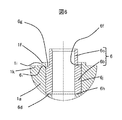
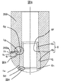
- FIG. 7 shows a state in which the cylinder 6 is assembled to the pump body 1a.
- the cylinder body 6 is assembled as shown in FIG. It arrange
- a cylinder fitting hole 6f into which the cylinder 6 is inserted is formed in the pump body 1a. It may be said that the cylinder fitting hole 6f and the cylinder side surface 6j are fitted. Further, a stepped portion is formed on the pressurizing chamber 11 side of the pump body 1a, and the bottom surface of the cylinder fitting hole held in contact with the cylinder end surface 6d at the tip of the cylinder 6 on the pressurizing chamber 11 side by the stepped portion. 6h is formed.
- a projecting portion 6e that projects locally from the cylinder 6 toward the cylinder fitting hole bottom surface 6h is formed on the cylinder end surface 6d. Since this protrusion 6e is formed in an annular shape so as to follow the circumferential shape of the cylinder, it is called an annular protrusion 6e in this embodiment.
- the annular protrusion 6e When the cylinder end surface 6d of the cylinder 6 is pressure-bonded to the cylinder fitting hole bottom surface 6h, the annular protrusion 6e is pressure-bonded to the cylinder fitting hole bottom surface 6h.
- the pressurized fuel is sealed so as not to leak to the low pressure side. It may be said that the annular protrusion 6e bites into the cylinder fitting hole bottom surface 6h.
- the material of the cylinder 6 is selected to be higher than the material hardness of the pump body 1a in order to support the reciprocating motion of the plunger 2. Therefore, the annular projection 6e bites into the pump body 1a, and the pump body 1a is plastically deformed, whereby the sealing function of the cylinder end surface 6d can be further enhanced.
- the annular protrusion 6e has a triangular shape, but a convex shape, a curved surface shape, or the like can be expected to have the same effect.
- FIG. 7 shows a state in which the cylinder 6 is assembled in the cylinder fitting hole 6f of the pump body 6, and 200 indicates a punch to which a load is applied by a pressurizing device such as a press machine.
- a convex portion 1f is formed which is convex on the opposite side to the insertion direction of the cylinder 6 (hereinafter simply referred to as “insertion direction”).
- the insertion direction of the cylinder 6 is from top to bottom in FIG. 7 and from bottom to top in FIG.
- the convex portion 1 f is compressed in the axial direction of the cylinder 6 by the punch pressurizing surface 200 a in the same direction as the insertion direction and starts plastic deformation, and the convex portion 1 f is deformed toward the inner peripheral side of the cylinder 6 as the punch 200 is lowered.
- the direction toward the central axis of the plunger 2 with respect to the cylinder 6 is referred to as the inner peripheral side, and the opposite is referred to as the outer peripheral side.
- the cylindrical cylinder 6 includes a large diameter portion 6b on the pressurizing chamber side and a small diameter portion 6c on the opposite side to the pressurizing chamber side.
- the cylinder 6 is formed with a small diameter portion 6c and a large diameter portion 6b in this order in the insertion direction.
- the press punch 200 can pressurize and plastically deform only the convex portion 1f of the pump body 1a with a part of the flat surface of the punch 200, so that the rigidity of the punch 200 can be increased. Therefore, even when die steel hardened as the material of the punch 200 is used, a high-strength material having a tensile strength of around 1000 MPa can be pressed and plastically bonded, and breakage of the punch 200 can be prevented.
- the convex portion 1f of the pump body 1a is a portion that plastically flows, but since the pressure is applied in the same direction as the axial insertion direction of the cylinder 6 by the punch pressurizing surface 200a, the entire convex portion 1f. Compressive stress is applied to the material, causing compressive deformation.
- the outer peripheral side of the convex portion 1 f before deformation is defined as a slope 1 g that spreads toward the outer peripheral side in the pressurizing direction (insertion direction of the cylinder 6). That is, the slope protrusion 1g is widened toward the end in the pressing direction.
- the convex portion 1f when the convex portion 1f is pressed by the punch pressurizing surface 200a, the convex portion 1f can be hardly deformed in the outer peripheral direction. Therefore, the convex portion 1f is plastically deformed while compressive stress is applied in the inner peripheral direction. Furthermore, since the entire convex portion 1f and the vicinity of the lower portion of the convex portion 1f can be plastically deformed under the compressive stress without causing local slip, cracking occurs even in a material having an elongation of 10% or less (for example, aluminum die casting). There is no plastic bonding.
- the inner peripheral side end face of the deformed convex portion 1f is located on the inner peripheral side with respect to the cylinder side surface 6j.
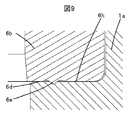
- the convex portion 1f is deformed. If the end on the outer peripheral side of the large-diameter portion 6b of the cylinder 6 and the end opposite to the insertion direction is called a cylinder shoulder portion 6g, the deformed convex portion 1f is finally as shown in FIG. Then, it is plastically deformed so as to cover the cylinder shoulder 6g.
- the end 1k of the pump body 1a opposite to the pressurizing chamber 11 has an inner peripheral surface (the inner peripheral surface of the cylinder fitting hole 6f) facing the outer peripheral surface (cylinder side surface 6j) of the cylinder 6.
- a protrusion formed from the outer peripheral side to the inner peripheral side is provided.
- the projecting portion is formed so as to project to the inner peripheral side of the cylinder 6 from the cylinder side surface 6j.
- the projecting portion is formed so as to project to the opposite side of the pressurizing chamber 11 with respect to the flat portion of the end 1k of the pump body 1a.
- the outer peripheral portion of the projecting portion (deformed convex portion 1f) is opposite to the pressurizing chamber 11 (in the insertion direction) as it goes from the flat portion of the end 1k of the pump body 1a toward the inner peripheral side.
- the taper 1g is formed so as to be inclined in the opposite direction.
- the inner peripheral portion of the projecting portion (deformed convex portion 1f) is connected to the pressurizing chamber 11 from the inner peripheral surface (the inner peripheral surface of the cylinder fitting hole 6f) facing the outer peripheral surface (cylinder side surface 6j) of the cylinder 6. It forms so that it may incline to an inner peripheral side as it goes to the other side (direction opposite to an insertion direction).
- the cylinder 6 is supported by the pressurization chamber side surface of the inner peripheral part of this protrusion part (deformed convex part 1f). Further, pressure is applied to the projecting portion (the projecting portion 1 f before deformation) of the pump body 1 a from the opposite side to the pressurizing chamber 11 in the insertion direction, so that the projecting portion (the projecting portion 1 f after deformation) is Contact with the side of the non-pressurizing chamber (cylinder shoulder 6g)
- a tapered portion 6i is formed in the cylinder shoulder portion 6g of the large diameter portion 6b of the cylinder 6 so as to be inclined toward the inner peripheral side toward the opposite side to the cylinder insertion direction. Accordingly, a wedge-shaped gap is provided between the cylinder side surface 6j and the cylinder fitting hole 6f and at the intersection between the cylinder side surface 6j and the cylinder shoulder portion 6g before the deformation of the convex portion 1f.
- the plastically flowed material in the tapered portion 6 i has a wedge shape, so that a reaction force can be generated not only from the pulling direction but also from the outer peripheral direction. As described above, the pulling force and residual deflection of the cylinder 6 can be increased by the tapered surface 6i.
- the load of the pressurizing device is also transmitted in the axial direction of the cylinder 6 through plastic deformation, and the protrusion 6e provided on the cylinder end surface 6d plastically deforms the cylinder fitting hole bottom surface 6h and bites into the cylinder.
- the end face 6d and the cylinder fitting hole bottom face 6h are pressure-bonded.
- the protrusion 6e bites the plastic cylinder deformation hole 6h.
- the surface roughness of the protrusion 6e is transferred to the surface roughness of the cylinder fitting hole bottom surface 6h, which affects the surface roughness of the cylinder fitting hole bottom surface 6h and the component accuracy such as the perpendicularity between the pump body 1a and the cylinder 6. Accordingly, the protrusion 6e and the cylinder fitting hole bottom surface 6h can be brought into close contact with each other sufficiently to seal the fluid, and the fuel sealing performance can be remarkably improved.
- FIG. 13 shows the relationship between the load, the coupling strength of the cylinder 6 and the residual deflection.
- the bond strength is almost constant between 160 and 220, but the residual strain increases with the load.
- the cause is considered to be a difference in work hardening due to plastic deformation of the pump body 1a, and in particular, it is considered that the yield stress of the material of the pump body 1a increases due to an increase in work hardening of the portion to be crimped to the tapered surface 6i. .
- the material of the pump body 1a covers the cylinder shoulder portion 6g by plastic bonding, and is pressed against the cylinder shoulder portion 6g, the tapered surface 6i of the cylinder 6 and the cylinder side surface 6j by residual stress, and further the axial direction of the cylinder 6 Is held by pressure bonding between the plastic coupling portion 1h and the cylinder fitting hole bottom surface 6h, and is firmly coupled to the cylinder 6.
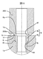
- 11 and 12 show another embodiment of the cylinder.
- the small diameter portion 6c forms the pressurizing chamber side and the large diameter portion 6b forms the counter pressurizing chamber side, contrary to FIG.
- the inner diameter of the cylinder fitting hole 6f is formed to be substantially the same as that of the large diameter portion 6b, and the inner peripheral surface of this inner diameter passes through the step portion (cylinder fitting hole bottom surface 6h) and is pressurized. It was configured to communicate with the chamber 11.
- the point that the inner diameter of the cylinder fitting hole 6f is formed to be substantially the same as that of the large diameter portion 6b is the same as in FIG. 7, but the diameter is further larger than the inner diameter of the cylinder fitting hole 6f.
- the cylinder fitting hole 6f is configured by connecting the first inner peripheral surface with a large inner diameter on the semi-pressurizing chamber side and the second inner peripheral surface with a small inner diameter on the pressurizing chamber side.
- the second inner peripheral surface is configured to communicate with the pressurizing chamber 11.
- the cylinder 6 is inserted into the pump body 1a and a cylinder fitting hole 6f formed in the pump body 1a. More specifically, the small diameter portion 6c of the cylinder 6 is inserted into the second inner peripheral surface and the large diameter portion 6b is inserted into the first inner peripheral surface. And the convex part 1f (projection part) previously provided in the peripheral part of the inlet_port
- entrance of the cylinder fitting hole 6f of the pump body 1a is compressed and deformed by being pressurized in the insertion direction of the cylinder. At this time, the convex portion 1 f and the material in the vicinity of the convex portion 1 f are plastically deformed toward the cylinder 6.
- the convex portion 1f and the material in the vicinity of the convex portion 1f are plastically deformed toward the inner peripheral side.
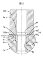
- the convex portion 1f is fixed by being plastically coupled so as to cover the cylinder shoulder portion 6g and the cylinder side surface 6j while being crimped.
- transformation is made into the inclined surface 1g which spreads to an outer peripheral side as it goes to a pressurization direction (insertion direction of the cylinder 6) similarly to FIG. That is, the slope is 1 g widening toward the end in the pressing direction.
- a slope 1g is formed which spreads on the outer peripheral side as it goes in the pressurizing direction (the insertion direction of the cylinder 6) on the outer peripheral side of the convex portion 1f.
- the projecting portion 1f (projecting portion) is formed on the pump body 1a to have a ring shape on the circumference.
- the cylinder fitting hole 6f of the pump body 1a has a cylinder fitting hole bottom surface 6h, and a cylinder end surface 6j contacting the cylinder fitting hole bottom surface 6h is pressure-bonded to the cylinder fitting hole bottom surface 6h by pressurization.
- the local annular projection 6e provided at the step between the large-diameter portion 6b and the small-diameter portion 6c presses and comes into close contact with the bottom surface 6h of the cylinder fitting hole, thereby leaking fuel pressurized in the pressurizing chamber 11 to the low-pressure side. It is sealed so that there is no.
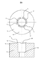
- the shape of the projecting portion 1f of the pump body 1a is a ring shape, but the projecting portion 1f having one or more discontinuous portions 1j can be expected to have the same effect. That is, the projecting portion (projecting portion 1f) is formed so as to project to the opposite side of the pressurizing chamber 11 with respect to the flat portion of the end 1k of the pump body 1a, but does not project over the entire circumference. Also, it may be configured so that only a part of it protrudes. Since the amount of plastic working can be reduced by using the discontinuous portion, the load to be deformed can be reduced, and as a result, the effect of suppressing the deformation amount to other parts of the pump body 1a can be expected. Further, the same effect can be expected even if the inclined surface 1g is changed to the vertical surface 1i.
- FIG. 5 shows an example of a convex portion 1f having three discontinuous portions 1j.
- the cylinder 6 is fitted into the cylinder fitting hole 6f having the cylinder fitting hole bottom surface 1h of the pump body 1a.
- a convex portion 1 f provided in advance at the peripheral edge of the inlet of the cylinder fitting hole 6 f of the pump body 1 a is a pressurizing surface 200 a of the punch 200, and a portion of the punch end surface away from the side surface of the punch 200 is substantially in the cylinder axial direction ( By compressing in the insertion direction), the material is compressed and deformed, and the convex portion 1f and the material in the vicinity of the convex portion 1f are plastically deformed in the cylinder direction (inner peripheral side).
- the cylinder shoulder portion and the cylinder side surface 6j are plastic-bonded so as to cover the cylinder shoulder portion and the cylinder side surface 6j.
- the cylinder end surface 6d contacting the cylinder fitting hole bottom surface 6h of the cylinder 6 is pressed against the cylinder fitting hole bottom surface 6h by pressurization, and the local protrusion 6e provided on the cylinder end surface 6d is a cylinder fitting hole bottom surface 6h.
- the material is plastically deformed to bite, and the biting part is pressed and adhered to perform sealing.
- the purpose of this example is that a high-strength material with high deformation resistance and low elongation, or a material with low elongation but low elongation, there is no cracking in the caulked portion, and the deformation resistance is high.
- a two-member joining method in which, when a high-strength material that is easily damaged by a pressure jig (punch) is caulked and bonded, the pressure jig (punch) is prevented from being damaged and plastically bonded (for example, caulking). Is.
- the coupling and fixing method of the present embodiment is not necessarily limited to the high-pressure fuel supply pump, and can be applied to the case where the other two members are coupled. That is, in the joining method of two members, the body having a bottomed hole and the bottomed hole are fitted, the fitting part is a cylindrical fitting part, and the fitting part is fitted into the bottomed hole of the body. And a convex portion provided in advance at the peripheral edge of the bottomed hole entrance of the body is pressed in a substantially axial direction (insertion direction) of the fitting component.
- the convex part is compressed and deformed, and the convex part and the material in the vicinity of the convex part are plastically deformed in the direction of the fitting part so as to cover the shoulder part of the fitting part and the fitting part side surface while being crimped.
- the outer peripheral side of the convex portion be a surface that spreads out toward the pressurizing direction.
- the convex portion is a pressing surface of the punch and is pressed in a substantially axial direction (insertion direction) of the fitting part at a part of the punch end surface away from the side surface of the punch.
- the cylinder and the body can be plastically bonded by compressive deformation without active shearing in the convex part and the vicinity of the convex part. it can. Moreover, since the rigidity of the plastic deformation portion is reduced by making the plastic deformation portion of the body convex, the deformation resistance of plastic coupling can be lowered.
- the cylinder-body coupling structure can be made compact by plastic coupling and has good sealing properties, and the pump body can be reduced in size, cost, and reliability.
- this bonding method can be widely applied as a two-member bonding method without being constrained by a high-pressure fuel supply pump, especially when plastically bonding a material with low elongation or plastically bonding a high-strength material. It is extremely effective.
Landscapes
- Engineering & Computer Science (AREA)
- Mechanical Engineering (AREA)
- General Engineering & Computer Science (AREA)
- Chemical & Material Sciences (AREA)
- Combustion & Propulsion (AREA)
- Fuel-Injection Apparatus (AREA)
Priority Applications (4)
| Application Number | Priority Date | Filing Date | Title |
|---|---|---|---|
| DE112016004267.1T DE112016004267T5 (de) | 2015-10-23 | 2016-10-05 | Hochdruck-Kraftstoffversorgungspumpe, Herstellungsverfahren dafür und Verfahren zum Verbinden zweier Elemente |
| JP2017546491A JP6501901B2 (ja) | 2015-10-23 | 2016-10-05 | 高圧燃料供給ポンプとその製造方法並びに2部材の結合方法 |
| CN201680060180.XA CN108138725B (zh) | 2015-10-23 | 2016-10-05 | 高压燃料供给泵及其制造方法以及两构件的结合方法 |
| US15/769,238 US10590897B2 (en) | 2015-10-23 | 2016-10-05 | High-pressure fuel supply pump, manufacturing method thereof, and method of bonding two members |
Applications Claiming Priority (2)
| Application Number | Priority Date | Filing Date | Title |
|---|---|---|---|
| JP2015-208528 | 2015-10-23 | ||
| JP2015208528 | 2015-10-23 |
Publications (1)
| Publication Number | Publication Date |
|---|---|
| WO2017068975A1 true WO2017068975A1 (ja) | 2017-04-27 |
Family
ID=58557433
Family Applications (1)
| Application Number | Title | Priority Date | Filing Date |
|---|---|---|---|
| PCT/JP2016/079568 Ceased WO2017068975A1 (ja) | 2015-10-23 | 2016-10-05 | 高圧燃料供給ポンプとその製造方法並びに2部材の結合方法 |
Country Status (5)
| Country | Link |
|---|---|
| US (1) | US10590897B2 (enExample) |
| JP (2) | JP6501901B2 (enExample) |
| CN (1) | CN108138725B (enExample) |
| DE (1) | DE112016004267T5 (enExample) |
| WO (1) | WO2017068975A1 (enExample) |
Families Citing this family (7)
| Publication number | Priority date | Publication date | Assignee | Title |
|---|---|---|---|---|
| DE102017203762A1 (de) * | 2017-03-08 | 2018-09-13 | Continental Automotive Gmbh | Kraftstoffhochdruckpumpe für ein Kraftstoffeinspritzsystem |
| JP6809520B2 (ja) * | 2017-09-29 | 2021-01-06 | 株式会社デンソー | 高圧ポンプ |
| DE102019204995B4 (de) * | 2019-04-08 | 2024-03-07 | Vitesco Technologies GmbH | Pumpe für ein Kraftfahrzeug und Verfahren zum Herstellen einer Pumpe |
| JP7326857B2 (ja) * | 2019-05-13 | 2023-08-16 | Jfeエンジニアリング株式会社 | 廃棄物焼却炉及び廃棄物焼却炉の給塵装置の制御方法 |
| CN115398090B (zh) * | 2020-04-14 | 2023-10-20 | 日立安斯泰莫株式会社 | 高压燃料供给泵和制造方法 |
| GB2600765B (en) * | 2020-11-10 | 2023-04-05 | Delphi Tech Ip Ltd | Fuel pump assembly |
| CN121039407A (zh) | 2023-05-08 | 2025-11-28 | 安斯泰莫株式会社 | 双构件的固定构造及高压燃料供给泵 |
Citations (10)
| Publication number | Priority date | Publication date | Assignee | Title |
|---|---|---|---|---|
| JPS5362022A (en) * | 1976-11-12 | 1978-06-03 | Maschf Augsburg Nuernberg Ag | Fuel injection pump for internal combustion engine and production apparatus of it |
| JPS6225018U (enExample) * | 1985-07-29 | 1987-02-16 | ||
| JPH0620304A (ja) * | 1992-06-30 | 1994-01-28 | Awa Eng Co | 光ディスクの製造方法 |
| JPH0642519A (ja) * | 1992-03-04 | 1994-02-15 | Toyota Motor Corp | シール機能を備えたウェルドナット |
| JP2002310300A (ja) * | 2001-04-13 | 2002-10-23 | Mitsubishi Electric Corp | 封止装置 |
| JP2008019985A (ja) * | 2006-07-13 | 2008-01-31 | Ricoh Co Ltd | 軸受抜け止め構造 |
| JP2008175384A (ja) * | 2006-12-20 | 2008-07-31 | Ntn Corp | 流体軸受装置用軸部材、およびその製造方法 |
| JP2009085232A (ja) * | 2007-09-27 | 2009-04-23 | Ntn Corp | 滑り軸受の固定方法 |
| JP2009185613A (ja) * | 2008-02-04 | 2009-08-20 | Hitachi Ltd | 高圧燃料ポンプ |
| JP2014088838A (ja) * | 2012-10-31 | 2014-05-15 | Hitachi Automotive Systems Ltd | 高圧燃料供給ポンプ |
Family Cites Families (14)
| Publication number | Priority date | Publication date | Assignee | Title |
|---|---|---|---|---|
| JPS5178676A (en) | 1974-12-28 | 1976-07-08 | Mishima Kosan Co Ltd | 2 makisenheijirogatajikimaruchibaibureeta |
| JPS54140153U (enExample) | 1978-03-24 | 1979-09-28 | ||
| JPS54127979U (enExample) | 1979-02-19 | 1979-09-06 | ||
| JP2002213470A (ja) | 2001-01-15 | 2002-07-31 | Nsk Ltd | 転がり軸受装置 |
| JP2002337683A (ja) | 2001-05-18 | 2002-11-27 | Unisia Jecs Corp | ブレーキ装置用液圧ユニットの液圧ポンプ |
| EP1394452A4 (en) * | 2001-06-04 | 2007-09-19 | Nok Corp | SEAL DEVICE |
| JP4148023B2 (ja) * | 2003-05-22 | 2008-09-10 | 株式会社デンソー | 中空成形品の成形方法および中空成形品 |
| DE102004063074B4 (de) | 2004-12-28 | 2013-03-07 | Robert Bosch Gmbh | Kolbenpumpe, insbesondere Kraftstoff-Hochdruckpumpe für eine Brennkraftmaschine |
| US8240918B2 (en) | 2006-12-20 | 2012-08-14 | Ntn Corporation | Shaft member for fluid bearing device and method of producing the same |
| DE102008056853A1 (de) * | 2008-11-12 | 2010-05-20 | Continental Teves Ag & Co. Ohg | Verschlussvorrichtung |
| JP5353472B2 (ja) * | 2009-06-23 | 2013-11-27 | 株式会社アドヴィックス | 詰栓構造 |
| JP5178676B2 (ja) | 2009-09-29 | 2013-04-10 | 日立オートモティブシステムズ株式会社 | 高圧燃料供給ポンプ |
| JP5372692B2 (ja) * | 2009-10-06 | 2013-12-18 | 日立オートモティブシステムズ株式会社 | 高圧燃料ポンプ |
| JP5593768B2 (ja) * | 2010-03-25 | 2014-09-24 | 日本精工株式会社 | 軸受装置 |
-
2016
- 2016-10-05 US US15/769,238 patent/US10590897B2/en active Active
- 2016-10-05 WO PCT/JP2016/079568 patent/WO2017068975A1/ja not_active Ceased
- 2016-10-05 CN CN201680060180.XA patent/CN108138725B/zh active Active
- 2016-10-05 DE DE112016004267.1T patent/DE112016004267T5/de active Pending
- 2016-10-05 JP JP2017546491A patent/JP6501901B2/ja active Active
-
2019
- 2019-03-19 JP JP2019050821A patent/JP6799102B2/ja active Active
Patent Citations (10)
| Publication number | Priority date | Publication date | Assignee | Title |
|---|---|---|---|---|
| JPS5362022A (en) * | 1976-11-12 | 1978-06-03 | Maschf Augsburg Nuernberg Ag | Fuel injection pump for internal combustion engine and production apparatus of it |
| JPS6225018U (enExample) * | 1985-07-29 | 1987-02-16 | ||
| JPH0642519A (ja) * | 1992-03-04 | 1994-02-15 | Toyota Motor Corp | シール機能を備えたウェルドナット |
| JPH0620304A (ja) * | 1992-06-30 | 1994-01-28 | Awa Eng Co | 光ディスクの製造方法 |
| JP2002310300A (ja) * | 2001-04-13 | 2002-10-23 | Mitsubishi Electric Corp | 封止装置 |
| JP2008019985A (ja) * | 2006-07-13 | 2008-01-31 | Ricoh Co Ltd | 軸受抜け止め構造 |
| JP2008175384A (ja) * | 2006-12-20 | 2008-07-31 | Ntn Corp | 流体軸受装置用軸部材、およびその製造方法 |
| JP2009085232A (ja) * | 2007-09-27 | 2009-04-23 | Ntn Corp | 滑り軸受の固定方法 |
| JP2009185613A (ja) * | 2008-02-04 | 2009-08-20 | Hitachi Ltd | 高圧燃料ポンプ |
| JP2014088838A (ja) * | 2012-10-31 | 2014-05-15 | Hitachi Automotive Systems Ltd | 高圧燃料供給ポンプ |
Also Published As
| Publication number | Publication date |
|---|---|
| JP6799102B2 (ja) | 2020-12-09 |
| CN108138725B (zh) | 2021-04-27 |
| US10590897B2 (en) | 2020-03-17 |
| DE112016004267T5 (de) | 2018-05-30 |
| CN108138725A (zh) | 2018-06-08 |
| JP6501901B2 (ja) | 2019-04-17 |
| US20180313313A1 (en) | 2018-11-01 |
| JP2019090425A (ja) | 2019-06-13 |
| JPWO2017068975A1 (ja) | 2018-06-14 |
Similar Documents
| Publication | Publication Date | Title |
|---|---|---|
| JP6799102B2 (ja) | 高圧燃料供給ポンプ及び結合方法 | |
| JP5501272B2 (ja) | 高圧燃料供給ポンプ | |
| JP2011080391A (ja) | 高圧燃料供給ポンプの吐出弁機構 | |
| CN110537014A (zh) | 高压燃料泵 | |
| JP5589121B2 (ja) | 高圧燃料供給ポンプ | |
| US12006901B2 (en) | Fuel pump | |
| WO2018092538A1 (ja) | 高圧燃料供給ポンプ | |
| JP6268279B2 (ja) | 高圧燃料供給ポンプ | |
| JP4585977B2 (ja) | 高圧燃料供給ポンプ及びその組立方法 | |
| JP6692303B2 (ja) | 高圧燃料ポンプ | |
| US12480465B2 (en) | Fuel pump | |
| US20220316470A1 (en) | Fuel Pump | |
| JP2019100268A (ja) | 燃料供給ポンプ | |
| JP2017160915A (ja) | 高圧燃料供給ポンプ | |
| JP2023071061A (ja) | 燃料ポンプ | |
| JP6959109B2 (ja) | リリーフ弁機構およびこれを備えた燃料供給ポンプ | |
| JP6596304B2 (ja) | 高圧燃料供給ポンプ | |
| JP2019100190A (ja) | 高圧燃料供給ポンプ | |
| JP6165674B2 (ja) | 高圧燃料供給ポンプ | |
| WO2024089843A1 (ja) | 燃料ポンプ | |
| JP2017072027A (ja) | 高圧燃料供給ポンプ | |
| JP2023169731A (ja) | 燃料ポンプ | |
| JP2018087549A (ja) | 高圧燃料供給ポンプ |
Legal Events
| Date | Code | Title | Description |
|---|---|---|---|
| 121 | Ep: the epo has been informed by wipo that ep was designated in this application |
Ref document number: 16857291 Country of ref document: EP Kind code of ref document: A1 |
|
| ENP | Entry into the national phase |
Ref document number: 2017546491 Country of ref document: JP Kind code of ref document: A |
|
| WWE | Wipo information: entry into national phase |
Ref document number: 112016004267 Country of ref document: DE |
|
| WWE | Wipo information: entry into national phase |
Ref document number: 15769238 Country of ref document: US |
|
| 122 | Ep: pct application non-entry in european phase |
Ref document number: 16857291 Country of ref document: EP Kind code of ref document: A1 |