WO2017065246A1 - 無段変速機 - Google Patents
無段変速機 Download PDFInfo
- Publication number
- WO2017065246A1 WO2017065246A1 PCT/JP2016/080455 JP2016080455W WO2017065246A1 WO 2017065246 A1 WO2017065246 A1 WO 2017065246A1 JP 2016080455 W JP2016080455 W JP 2016080455W WO 2017065246 A1 WO2017065246 A1 WO 2017065246A1
- Authority
- WO
- WIPO (PCT)
- Prior art keywords
- link
- pulley
- chain
- continuously variable
- variable transmission
- Prior art date
- Legal status (The legal status is an assumption and is not a legal conclusion. Google has not performed a legal analysis and makes no representation as to the accuracy of the status listed.)
- Ceased
Links
Images



Classifications
-
- F—MECHANICAL ENGINEERING; LIGHTING; HEATING; WEAPONS; BLASTING
- F16—ENGINEERING ELEMENTS AND UNITS; GENERAL MEASURES FOR PRODUCING AND MAINTAINING EFFECTIVE FUNCTIONING OF MACHINES OR INSTALLATIONS; THERMAL INSULATION IN GENERAL
- F16G—BELTS, CABLES, OR ROPES, PREDOMINANTLY USED FOR DRIVING PURPOSES; CHAINS; FITTINGS PREDOMINANTLY USED THEREFOR
- F16G13/00—Chains
- F16G13/02—Driving-chains
- F16G13/06—Driving-chains with links connected by parallel driving-pins with or without rollers so-called open links
-
- F—MECHANICAL ENGINEERING; LIGHTING; HEATING; WEAPONS; BLASTING
- F16—ENGINEERING ELEMENTS AND UNITS; GENERAL MEASURES FOR PRODUCING AND MAINTAINING EFFECTIVE FUNCTIONING OF MACHINES OR INSTALLATIONS; THERMAL INSULATION IN GENERAL
- F16H—GEARING
- F16H55/00—Elements with teeth or friction surfaces for conveying motion; Worms, pulleys or sheaves for gearing mechanisms
- F16H55/32—Friction members
- F16H55/36—Pulleys
- F16H55/49—Features essential to V-belts pulleys
-
- F—MECHANICAL ENGINEERING; LIGHTING; HEATING; WEAPONS; BLASTING
- F16—ENGINEERING ELEMENTS AND UNITS; GENERAL MEASURES FOR PRODUCING AND MAINTAINING EFFECTIVE FUNCTIONING OF MACHINES OR INSTALLATIONS; THERMAL INSULATION IN GENERAL
- F16H—GEARING
- F16H9/00—Gearings for conveying rotary motion with variable gear ratio, or for reversing rotary motion, by endless flexible members
- F16H9/02—Gearings for conveying rotary motion with variable gear ratio, or for reversing rotary motion, by endless flexible members without members having orbital motion
- F16H9/04—Gearings for conveying rotary motion with variable gear ratio, or for reversing rotary motion, by endless flexible members without members having orbital motion using belts, V-belts, or ropes
- F16H9/12—Gearings for conveying rotary motion with variable gear ratio, or for reversing rotary motion, by endless flexible members without members having orbital motion using belts, V-belts, or ropes engaging a pulley built-up out of relatively axially-adjustable parts in which the belt engages the opposite flanges of the pulley directly without interposed belt-supporting members
Definitions
- the present invention relates to a continuously variable transmission having a fixed pulley, a movable pulley, and a chain sandwiched between these pulleys.
- continuously variable transmissions capable of continuously changing the gear ratio have been put to practical use as, for example, vehicle transmissions.
- an endless belt such as a belt or a chain is wound around a primary pulley and a secondary pulley, and a thrust applied to a movable pulley of the primary pulley and the secondary pulley causes Power is transmitted using the friction force generated between them.
- a groove with an R-shaped cross section is formed in the circumferential direction at the root portion of the sheave of the fixed pulley (the portion where the sheave surface of the fixed pulley rises from the pulley shaft) (for example, Patent Document 1).
- this groove is referred to as an R escape groove.
- This R relief groove is formed by forming an R shape as a recess to relieve stress concentration on the root of the sheave.
- the R shape does not interfere with the endless belt. ing.
- the sheave root becomes thinner by the depth of the R clearance groove, and the strength of the pulley shaft decreases.
- the present invention was devised in view of the problems as described above, and while mitigating stress concentration of the fixed pulley, it is possible to improve the strength of the pulley shaft and to increase the ratio coverage as compared with the prior art.
- An object of the present invention is to provide a continuously variable transmission.
- a continuously variable transmission includes a fixed pulley having a pulley shaft and a first sheave surface, a movable pulley having a second sheave surface, the fixed pulley, and the movable pulley.
- a continuously variable transmission having a chain wound around a groove between the pulley and the chain, wherein the chain includes a plurality of link rows formed of a plurality of link plates arranged in a width direction of the chain;
- a link pin that connects a plurality of link plates, and the pulley shaft of the fixed pulley has an enlarged diameter portion that is a curved surface that gradually increases in diameter as it approaches the first sheave surface, When viewed from the radial direction of the pulley shaft when the winding diameter of the chain is minimized, the chain is disposed at a position that does not overlap the enlarged diameter portion.
- the restricting means is a retainer pin attached to the link pin, and the retainer pin is located between the link row and the first sheave surface.
- the pulley shaft of the fixed pulley has the enlarged portion that is a curved surface whose diameter gradually increases as it approaches the first sheave surface.
- the ratio coverage can be increased by reducing the hook diameter.
- the link row is arranged at a position that does not overlap the enlarged diameter part when viewed from the radial direction of the pulley shaft when the chain winding diameter is minimized, so that the chain winding diameter is minimum.
- the link row is closest to the enlarged diameter portion, interference between the link row and the enlarged diameter portion can be prevented.
- FIG.1 It is a schematic diagram which shows the structure of the principal part of the continuously variable transmission as one Embodiment of this invention, (a) is the side view, (b) is the longitudinal cross-sectional view which expanded the principal part of the secondary pulley. is there. It is sectional drawing which shows typically each principal part of the secondary pulley and chain which concern on one Embodiment of this invention, and is the X section enlarged view of FIG.1 (b). It is a side view which shows typically each principal part of the secondary pulley and chain which concern on one Embodiment of this invention. It is a front view which shows typically the principal part of the chain which concerns on one Embodiment of this invention. It is a perspective view showing typically the composition of the link board concerning one embodiment of the present invention. It is sectional drawing which shows typically each principal part of the secondary pulley and chain of one Embodiment of this invention.
- the inner peripheral side in the present invention refers to the inner side in the radial direction of the pulley shaft.
- the inner side in the radial direction of the primary shaft means the secondary pulley or the chain wrapped around the secondary pulley.
- the inner peripheral side of the part it refers to the inner side in the radial direction of the secondary shaft.
- the outer peripheral side in the present invention means the outer side in the radial direction of the pulley shaft.
- the outer side in the radial direction of the primary shaft means the secondary pulley or the part of the chain wound around the secondary pulley. Is the outer side in the radial direction of the secondary shaft.
- FIG. 1 is a schematic diagram showing a configuration of a main part of a continuously variable transmission as an embodiment of the present invention, where (a) is a side view thereof and (b) is an enlarged main part of a secondary pulley. It is a longitudinal cross-sectional view. 1 (a) and 1 (b), the chain 4 is shown by simplifying only the track thereof by a one-dot chain line.
- a continuously variable transmission (hereinafter also referred to as CVT) 1 includes an endless pulley wound around a primary pulley 2, a secondary pulley 3, and these primary pulley 2 and secondary pulley 3.
- a belt-like chain 4 is provided.
- the primary pulley 2 has a primary shaft (pulley shaft) 21A, and the primary shaft 21A is connected to an engine (not shown) via a torque converter (not shown).
- the secondary pulley 3 has a secondary shaft (pulley shaft) 31A disposed in parallel with the primary shaft 21A.
- the secondary shaft 31A is connected to a driving wheel (not shown) via a speed reduction mechanism, a differential mechanism, etc. (not shown). It is connected.
- the secondary pulley 3 includes a fixed pulley 31 and a movable pulley 32 disposed to face the fixed pulley 31.
- the fixed pulley 31 includes the secondary shaft 31A and a fixed pulley main body 31B fixed to the secondary shaft 31A.
- the movable pulley 32 is provided so as to be locked in the rotational direction with respect to the secondary shaft 31A and movable in the axial direction A of the secondary shaft 31A.
- the sheave surface (first sheave surface) 31a of the fixed pulley 31 that faces each other and the sheave surface (second sheave surface) 32a of the movable pulley 32 are gradually spaced from each other toward the outer peripheral side (radially outward).
- a V-shaped groove having a V-shaped cross section is formed between the sheave surface 31a and the sheave surface 32a.
- the primary pulley 2 includes a fixed pulley and a movable pulley disposed to face the fixed pulley, like the secondary pulley 3.
- the fixed pulley includes the primary shaft 21A and the primary pulley.
- the movable pulley is provided so as to be locked to the primary shaft 21A in the rotational direction and movable in the axial direction A of the primary shaft 21A.
- the sheave surface of the fixed pulley and the sheave surface of the movable pulley that are opposed to each other of the primary pulley 2 are formed in a conical shape in which the mutual distance gradually increases toward the outer peripheral side, and the sheave surface of the fixed pulley and the sheave of the movable pulley A V-shaped groove having a V-shaped cross section is formed between the surface and the surface.
- the position of the movable pulley 32 of the primary pulley 2 and the movable pulley 32 of the secondary pulley 3 is controlled by a hydraulic actuator (not shown).
- a hydraulic actuator not shown.
- FIG. 2 is a schematic diagram showing the configuration of the main parts of the secondary pulley and the chain in a state where the gear ratio according to the embodiment of the present invention is the highest (that is, a state where the winding diameter of the chain on the secondary pulley is minimum).
- 4 is a cross-sectional view taken along the line EE of FIG. 4 (however, the hatch indicating the cross section of the link plate 42 is omitted), and is an enlarged view of a portion X in FIG.
- FIG. 3 is a side view schematically showing the main parts of the secondary pulley and the chain in the state where the gear ratio is the highest according to one embodiment of the present invention.
- FIG. 4 is a front view schematically showing the main part of the chain according to one embodiment of the present invention.
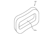
- FIG. 5 is a perspective view schematically showing a configuration of a link plate according to an embodiment of the present invention.
- FIG. 6 is a cross-sectional view schematically showing main parts of the secondary pulley and the chain according to the embodiment of the present invention, and is a view showing a state where the gear ratio is on the low side as compared with FIG.
- the fixed pulley 31 of the secondary pulley 3 Since the fixed pulley of the primary pulley 2 and the fixed pulley 31 of the secondary pulley 3 are configured in the same manner as described above, the fixed pulley 31 of the secondary pulley 3 will be described as an example.
- the secondary shaft 31A gradually increases in diameter as it approaches the sheave surface 31a, and extends over the entire length of the secondary shaft 31A. It has an enlarged diameter portion 31b that is larger than the diameter D of the other portion.
- the dashed-dotted line in FIG. 2 has shown the virtual extended surface which extended linearly the outer peripheral surface of the part except the sheave surface 31a and the diameter-expanded part 31b of the secondary shaft 31A, and it is outside this extended surface. Is defined as the enlarged diameter portion 31b.
- the enlarged diameter portion 31b is provided over the entire circumference of the secondary shaft 31A.
- the enlarged-diameter portion 31b has a constant cross-sectional shape, and the outer edge of the cross-section smoothly connects the sheave surface 31a of the fixed pulley 31 and the outer peripheral surface of the secondary shaft 31A, and the secondary shaft 31A and the sheave surface 31a. It has an R shape (arc shape) slightly recessed to the side.
- the secondary shaft 31A is provided with an R at the base of the fixed pulley 31 (an R curved surface is formed). Since the secondary shaft 31A tends to concentrate stress at the base of the fixed pulley 31, the stress concentration is reduced by attaching R to the base.
- the chain 4 is configured as shown in FIGS. That is, the chain 4 is configured in an endless manner by connecting a plurality of link plates 42 along a chain traveling direction C orthogonal to the axial direction A, but the axial direction (hereinafter referred to as the chain width direction or simply the width direction).
- A) A plurality of link plates 42 are also provided in A to form a belt shape so that a large force can be transmitted.
- Each link plate 42 is connected by inserting a link pin 43 extending in the axial direction A as will be described later.
- the link plates 42 are overlapped in the chain travel direction C and the chain width direction A (that is, The end portions of the link plates 42 are arranged so as to overlap each other.
- the plurality of link plates 42 are arranged side by side in the chain width direction A.
- the row (row) of the plurality of link plates 42 arranged side by side in this way is The description will be given by defining the link row 41A and the link row 41B.
- the number of link plates 42 constituting the link row 41 ⁇ / b> A and the link row 41 ⁇ / b> B is shown as a smaller number than in FIG. 2 for convenience.
- link row 41A and the link row 41B will be referred to as the link row 41 when they are not particularly distinguished.
- the link row 41A and the link row 41B adjacent to each other in the traveling direction C of the chain 4 are connected, and the link pin 43 is connected to the link plate 42 constituting the link row 41A and the link row 41B. Connect by inserting.
- one end of the opening 42a of the link plate 42 of the link row 41A overlaps with the other end of the opening 42a of the link plate 42 of the link row 41B adjacent to one end side of the link row 41A, and the link of the link row 41A.
- the other end of the opening 42a of the plate 42 and the one end of the opening 42a of the link plate 42 of the link row 41B adjacent to the other end side of the link row 41A are arranged in an overlapping manner.
- overlapping portions with the opening 42a of the adjacent link plate 42 are locations where the pair of link pins 43 are respectively inserted (that is, the openings 41a of the link row 41).
- the pair of link pins 43 are respectively inserted into the openings 41a, whereby the link row 41A and the link row 41B are connected to each other in a bendable manner to form the chain 4.
- Each of the pair of link pins 43 has a curved back surface 43a, and the curved back surface 43a is back-to-back, and is inserted through the opening 41a.
- both end surfaces 43b of the link pin 43 are formed as inclined surfaces corresponding to the inclination of the sheave surface 31a and the sheave surface 32a so as to make frictional contact with the sheave surface 31a and the sheave surface 32a, respectively.
- the link plate 42 is formed with the opening 42a through which the link pin 43 is inserted, and the plurality of link plates 42 have the link pin 43 inserted through the openings 42a. Thus, they are bundled in the link row 41.
- the opening 41a through which the link pin 43 is inserted to connect adjacent link rows 41 is formed at both ends of each opening 42a by arranging a plurality of openings 42a of the link plate 42 in the chain width direction A. Has been.
- the link pin 43 bundles the link plates 42 arranged in the chain width direction A to form the link row 41 and simultaneously connects the link row 41 arranged in the traveling direction C to form the chain 4.
- each link pin 43 On the peripheral surface of each link pin 43, a retainer pin 44 (regulating means) is fixed between the link row 41 and the sheave surface 31 a of the fixed pulley 31. And a retainer pin 45 is fixed between the sheave surface 32 a of the movable pulley 32.
- the plurality of link plates 42 inserted into the link pin 43 are prevented from being detached from the link pin 43 by the retainer pin 44 and the retainer pin 45. That is, the link plate 42 is restricted from moving toward the fixed pulley 31 by the retainer pin 44 and is restricted from moving toward the movable pulley 32 by the retainer pin 45.
- the installation range B of the link plate 42 is defined by the retainer pin 44 and the retainer pin 45.
- the link row 41 is viewed from the radial direction R of the secondary shaft 31 ⁇ / b> A when the winding diameter of the chain 4 is the minimum, the link row 41 is arranged only at a position that does not overlap the enlarged diameter portion 31 b. As shown, a retainer pin 44 is disposed.
- the retainer pin 44 when the winding diameter of the chain 4 is minimum, has a portion 44a closest to the link plate 42 on the side of the movable pulley 32 (from the enlarged diameter portion 31b) by ⁇ A from the enlarged diameter portion 31b. It is arranged so that it is located on the side to be separated.
- winding diameter of the chain 4 around the primary pulley 2 is the lowest at the lowest gear ratio.
- the link row 41 has an enlarged portion when viewed from the radial direction R as shown in FIG. It may overlap with 31b. That is, in the state shown in FIG. 6, the link row 41 is separated from the enlarged diameter portion 31b in the radial direction R. Therefore, even if it overlaps with the enlarged diameter portion 31b when viewed from the radial direction R, the enlarged diameter portion. It does not interfere with 31b.
- the installation range B of the link plate 42 is divided into a range B1 and a range B2 with the center line CL in the width direction A of the chain 4 as a boundary, and the range B1 between the center line CL and the movable pulley 32 is Is arranged to be larger than the range B2 between the center line CL and the fixed pulley 31.
- the link pin 43 is separated in the radial direction R from the enlarged diameter portion 31b. is doing.
- the height (dimension in the radial direction R) of the enlarged diameter portion 31b is set so as not to interfere with the link pin 43 even when the winding diameter of the chain 4 is minimized.
- the secondary shaft 31A is provided with an enlarged diameter portion 31b at the root of the sheave surface 31a of the fixed pulley 31.
- the secondary shaft 31A is thicker at the root of the sheave surface 31a than the other portions due to the presence of the enlarged diameter portion 31b.
- the diameter of the secondary shaft 31A is the same, the strength of the secondary shaft 31A is improved as compared with the conventional configuration.
- the secondary shaft 31A when the strength of the secondary shaft 31A is equal to that of the conventional configuration, the secondary shaft 31A can be made thinner than the conventional configuration, and as a result, the minimum winding diameter of the chain can be made smaller than the conventional configuration.
- the diameter-expanded portion 31b is formed in a smooth R-curved surface whose diameter gradually increases as the sheave surface 31a of the fixed pulley 31 is approached, the concentration of stress on the root of the fixed pulley 31 can be reduced.
- the R clearance groove 31c employed in the conventional structure has a shape that rises after sinking to the center side of the secondary pulley shaft 31A, and therefore the bottom 31d of the R clearance groove 31c. In this case, the curvature increases and stress tends to concentrate. On the other hand, since the enlarged diameter portion 31b does not sink to the center side of the secondary pulley shaft 31A, the overall curvature is small, and the stress can be more effectively distributed compared to the R escape groove 31c. Can do.
- the presence of the enlarged diameter portion 31b improves the strength of the secondary shaft 31A and reduces the concentration of stress on the root of the fixed pulley 31.
- the link row 41 can be used as the secondary shaft even when the winding diameter of the chain 4 on the secondary pulley 3 is minimized.
- it is arranged at a position that does not overlap with the enlarged diameter portion 31b (in other words, even when the winding diameter of the chain 4 on the secondary pulley 3 is minimized, the link The installation range B of the row 41 with respect to the chain width direction A is limited to a range in which the link row 41 and the enlarged diameter portion 31b do not interfere with each other). Therefore, even when the winding diameter of the chain 4 is minimized and the link row 41 is closest to the enlarged diameter portion 31b, interference between the link row 41 and the enlarged diameter portion 31b can be prevented.
- the chain 4 can be left-right symmetric (symmetric with respect to the center line CL), and either one of the left and right end faces 43b of the link pin 43 faces the enlarged diameter portion 31b.
- the chain 4 can be wound around the secondary pulley 3, one link row 41 can be obtained by adopting the configuration shown in FIG. 2 (a configuration in which more link plates 42 are arranged in the range B1 than in the range B2). The strength of the chain 4 can be improved by increasing the number of hitting link plates 42.
- the restricting means for restricting the movement of the link plate 42 toward the enlarged diameter portion 31b is configured by the retainer pin 44.
- the restricting means can restrict the movement of the link plate 42,
- the shape of the pin is not limited to that of the retainer pin 44.
- the restricting means may be constituted by an annular convex portion formed over the entire circumference of the link pin 43.
Landscapes
- Engineering & Computer Science (AREA)
- General Engineering & Computer Science (AREA)
- Mechanical Engineering (AREA)
- Transmissions By Endless Flexible Members (AREA)
- Pulleys (AREA)
Abstract
固定プーリ(31)と、可動プーリ(32)との間の溝に巻き掛けられたチェーン(4)は、複数のリンク板(42)から構成された複数のリンク列(41)と、複数のリンク板(42)を連結するリンクピン(43)と、を有する。固定プーリ(31)のプーリ軸(31A)は、第1シーブ面(31a)に近づくにつれて径が漸増する曲面である拡径部(31b)を有する。リンク列(41)は、チェーン(4)の巻掛径が最小となったときにプーリ軸(31A)の径方向(R)から視た場合において、拡径部(31b)と重ならない位置に配置されている。
Description
本発明は、固定プーリと、可動プーリと、これらのプーリの間に挟まれたチェーンとを有する、無段変速機に関する。
従来、変速比を連続的に変更できる無段変速機が、例えば車両用変速機として実用化されている。
無段変速機では、プライマリプーリとセカンダリプーリとにベルトやチェーン等の無端帯状体が巻き掛けられ、プライマリプーリ及びセカンダリプーリの可動プーリに加える推力により、プライマリプーリ及びセカンダリプーリと無端帯状体との間に発生した摩擦力を用いて動力を伝達する。
このような無段変速機では、一般的に、固定プーリのシーブ付け根部(プーリ軸から固定プーリのシーブ面が立ち上がる部分)に、R形状の横断面の溝が周方向に形成されている(例えば特許文献1)。以下、この溝をR逃げ溝という。
このR逃げ溝は、シーブ付け根部への応力の集中を緩和するためのR形状を凹所として形成したものである。
無端帯状体と、固定プーリのシーブ付け根部とが干渉してしまうと、無端帯状体やシーブ付け根部に傷が付いてしまうおそれがある。
そこで、R形状を凹所とすることによって、無端帯状体が変速比に応じてプーリへの巻掛径が小さくなってプーリ軸へ近づいたときに、R形状が無端帯状体と干渉しないようにしている。
しかしながら、R逃げ溝が形成されると、このR逃げ溝の深さ分だけシーブ付け根部が細くなってプーリ軸の強度が低下してしまう。
この強度の低下を、プーリ軸の径を大きくすることで相殺することも考えられるが、プーリ軸の径を大きくすると、無端帯状体の最小巻掛径が大きくなってレシオカバレッジ(=変速比の変更幅)が狭くなってしまう。
本発明は、上記のような課題に鑑み創案されたもので、固定プーリの応力集中を緩和すると共に、従来よりも、プーリ軸の強度を向上させることや、レシオカバレッジを大きくすることができるようにした、無段変速機を提供することを目的とする。
(1)上記の目的を達成するために、本発明の無段変速機は、プーリ軸及び第1シーブ面を有する固定プーリと、第2シーブ面を有する可動プーリと、前記固定プーリと前記可動プーリとの間の溝に巻き掛けられたチェーンと、を有する無段変速機であって、前記チェーンは、前記チェーンの幅方向に並ぶ複数のリンク板から構成された複数のリンク列と、前記複数のリンク板を連結するリンクピンと、を有し、前記固定プーリの前記プーリ軸は、前記第1シーブ面に近づくにつれて径が漸増する曲面である拡径部を有し、前記リンク列は、前記チェーンの巻掛径が最小となったときに前記プーリ軸の径方向から視た場合において、前記拡径部と重ならない位置に配置されている。
(2)前記リンク列の前記拡径部側への移動を規制する規制手段を有することが好ましい。
(3)前記規制手段は、前記リンクピンに取り付けられたリテーナピンであり、前記リテーナピンは、前記リンク列と前記第1シーブ面との間に位置することが好ましい。
(4)前記リンク板は、前記チェーンの幅方向に関する中心線と前記固定プーリとの間よりも、前記中心線と前記可動プーリとの間に多数配置されていることが好ましい。
本発明の無段変速機によれば、固定プーリのプーリ軸は、第1シーブ面に近づくにつれて径が漸増する曲面である拡径部を有しているので、この拡径部の存在によりプーリ軸の強度を向上させると共に拡径部の曲面によりプーリ軸の応力の集中を緩和して、従来よりもプーリ軸の強度を向上させることや、従来よりもプーリ軸を小径化ひいてはチェーンの最小巻掛径を小径化してレシオカバレッジを大きくすることができる。
また、リンク列は、チェーンの巻掛径が最小となったときにプーリ軸の径方向から視た場合において、拡径部と重ならない位置に配置されているので、チェーンの巻掛径が最小となってリンク列が拡径部に最接近した時でも、リンク列と拡径部との干渉を防止することができる。
以下、図面を参照して、本発明の実施の形態について説明する。
なお、以下に示す実施形態はあくまでも例示に過ぎず、以下の実施形態で明示しない種々の変形や技術の適用を排除する意図はない。
以下の実施形態の各構成は、それらの趣旨を逸脱しない範囲で種々変形して実施することができるとともに、必要に応じて取捨選択することができ、あるいは適宜組み合わせることが可能である。
なお、本発明でいう内周側とはプーリ軸の径方向で内側をいう。つまり、プライマリプーリの部位や、プライマリプーリに巻き掛けられたチェーンの部位について内周側といった場合には、プライマリ軸の径方向で内側をいい、セカンダリプーリや、セカンダリプーリに巻き掛けられたチェーンの部位について内周側といった場合には、セカンダリ軸の径方向で内側をいう。
同様に、本発明でいう外周側とはプーリ軸の径方向で外側をいう。つまり、プライマリプーリの部位や、プライマリプーリに巻き掛けられたチェーンの部位について外周側といった場合には、プライマリ軸の径方向で外側をいい、セカンダリプーリや、セカンダリプーリに巻き掛けられたチェーンの部位について外周側といった場合には、セカンダリ軸の径方向で外側をいう。
[1.無段変速機の要部構成]
本発明の一実施形態としての無段変速機の要部の構成について図1(a),(b)を参照して説明する。
本発明の一実施形態としての無段変速機の要部の構成について図1(a),(b)を参照して説明する。
図1は、本発明の一実施形態としての無段変速機の要部の構成を示す模式図であって、(a)はその側面図、(b)はそのセカンダリプーリの要部を拡大した縦断面図である。なお、図1(a),(b)では、チェーン4をその軌道のみ一点鎖線で簡略化して示している。
図1(a)に示すように、無段変速機(以下、CVTともいう)1は、プライマリプーリ2と、セカンダリプーリ3と、これらのプライマリプーリ2とセカンダリプーリ3とに巻き掛けられた無端帯状のチェーン4とを備えて構成されている。
プライマリプーリ2は、プライマリ軸(プーリ軸)21Aを有しており、このプライマリ軸21Aは図示しないトルクコンバータ等を介して図示しないエンジンに連結されている。
セカンダリプーリ3は、プライマリ軸21Aと平行に配置されたセカンダリ軸(プーリ軸)31Aを有しており、このセカンダリ軸31Aは、図示しない減速機構や差動機構等を介して図示しない駆動輪に連結されている。
図1(b)に示すように、セカンダリプーリ3は、固定プーリ31と、この固定プーリ31に対向して配置された可動プーリ32とを備えている。
固定プーリ31は、前記のセカンダリ軸31Aと、セカンダリ軸31Aに固定された固定プーリ本体31Bとを備えている。
可動プーリ32は、セカンダリ軸31Aに対して回転方向に係止され且つ、セカンダリ軸31Aの軸方向Aへ移動可能に設けられている。
相互に対面する固定プーリ31のシーブ面(第1シーブ面)31aと可動プーリ32のシーブ面(第2シーブ面)32aとは、外周側(径方向外側)に向かうに従って相互の間隔が徐々に広がる円錐状に形成され、シーブ面31aとシーブ面32aとの間に断面がV字状のV溝を形成している。
図示しないが、プライマリプーリ2は、セカンダリプーリ3と同様に、固定プーリと、この固定プーリに対向して配置された可動プーリとを備えており、固定プーリは、前記のプライマリ軸21Aと、プライマリ軸21Aに固定された固定プーリ本体とを備え、可動プーリは、プライマリ軸21Aに対して回転方向に係止され且つプライマリ軸21Aの軸方向Aへ移動可能に設けられている。
プライマリプーリ2の相互に対向する固定プーリのシーブ面と可動プーリのシーブ面とは、外周側に向かうに従って相互の間隔が徐々に広がる円錐状に形成され、固定プーリのシーブ面と可動プーリのシーブ面との間に断面がV字状のV溝を形成している。
プライマリプーリ2の可動プーリ及びセカンダリプーリ3の可動プーリ32はそれぞれ図示しない油圧アクチュエータによって軸方向Aの位置を制御される。これにより、V溝の幅が変化してチェーン4とシーブ面31a及びシーブ面32aとの接触半径(巻掛径)が変化し、変速比が変化する。
[2.固定プーリ及びチェーンの詳細構成]
本発明の一実施形態に係るセカンダリプーリの固定プーリ及びチェーンの詳細構成を、図2~図6を参照して説明する。
本発明の一実施形態に係るセカンダリプーリの固定プーリ及びチェーンの詳細構成を、図2~図6を参照して説明する。
図2は、本発明の一実施形態に係る変速比が最ハイの状態(すなわちチェーンのセカンダリプーリへの巻掛径が最小の状態)におけるセカンダリプーリ及びチェーンの各要部の構成を示す模式図であって図4のE-E断面図(但し、リンク板42の断面を示すハッチは省略)であって、図1(b)のX部拡大図である。
図3は、本発明の一実施形態に係る変速比が最ハイの状態におけるセカンダリプーリ及びチェーンの各要部を模式的に示す側面図である。
図4は、本発明の一実施形態に係るチェーンの要部を模式的に示す正面図である。
図5は、本発明の一実施形態に係るリンク板の構成を模式的に示す斜視図である。
図6は、本発明の一実施形態のセカンダリプーリ及びチェーンの各要部を模式的に示す断面図であり、図2よりも変速比がロウ側の状態を示す図である。
なお、プライマリプーリ2の固定プーリとセカンダリプーリ3の固定プーリ31とは上述したように同様に構成されているので、セカンダリプーリ3の固定プーリ31を例に挙げて説明する。
図2に網点を付して示すように、固定プーリ31のシーブ面31aの付け根において、セカンダリ軸31Aは、シーブ面31aに近づくにつれて径が漸増し、且つ、全長に亘ってセカンダリ軸31Aの他の部分の直径Dよりも拡径した拡径部31bを有している。
図2中の一点鎖線は、シーブ面31a及びセカンダリ軸31Aの拡径部31bを除いた部分の外周面を直線的に延長した仮想的な延長面を示しており、この延長面よりも外方の部分が拡径部31bとして規定される。
拡径部31bは、セカンダリ軸31Aの全周に亘って設けられている。拡径部31bは、一定した横断面形状を有しており、横断面の外縁は、固定プーリ31のシーブ面31aとセカンダリ軸31Aの外周面とを滑らかに繋ぎ且つセカンダリ軸31Aやシーブ面31a側に僅かに窪んだR形状(円弧形状)をしている。
換言すれば、セカンダリ軸31Aは、固定プーリ31の付け根において全周に亘ってRが付けられている(R曲面が形成されている)。セカンダリ軸31Aは、固定プーリ31の付け根において応力が集中しやすいため、付け根にRを付けることで応力の集中を緩和するようにしている。
チェーン4は、図2~図5に示すように構成されている。
つまり、チェーン4は、複数のリンク板42が、軸方向Aと直交するチェーン進行方向Cに沿って連結されて無端状に構成されるが、軸方向(以下、チェーン幅方向又は単に幅方向ともいう)Aにも複数のリンク板42を配備して帯状とすることで大きな力を伝達できるようにしている。
つまり、チェーン4は、複数のリンク板42が、軸方向Aと直交するチェーン進行方向Cに沿って連結されて無端状に構成されるが、軸方向(以下、チェーン幅方向又は単に幅方向ともいう)Aにも複数のリンク板42を配備して帯状とすることで大きな力を伝達できるようにしている。
各リンク板42は、後述するように軸方向Aに延在するリンクピン43を挿通することで連結される。リンクピン43により、チェーン幅方向A及びチェーン進行方向Cに並ぶリンク板42を同時に連結するためには、各リンク板42を、チェーン進行方向C及びチェーン幅方向Aに重なりを持たせつつ(即ち、各リンク板42の端部を互いに重複させて)並べることになる。
ここでは、チェーン進行方向Cの同位相位置において、複数のリンク板42がチェーン幅方向Aに横並びするようにしており、以下、このように横並びした複数のリンク板42の列(横列)を、リンク列41A及びリンク列41Bと規定して説明する。
なお、図4では、リンク列41A及びリンク列41Bを構成するリンク板42の各枚数を便宜的に図2よりも少ない枚数で示している。
以降、リンク列41A及びリンク列41Bを特に区別しない場合には、リンク列41と表記する。
詳細には、図3及び図4に示すように、チェーン4の進行方向Cに隣り合うリンク列41A及びリンク列41Bを、リンク列41Aやリンク列41Bを構成するリンク板42にリンクピン43を挿入することで連結する。
つまり、リンク列41Aのリンク板42の開口42aの一端と、このリンク列41Aの一端側に隣接するリンク列41Bのリンク板42の開口42aの他端とを重複させると共に、リンク列41Aのリンク板42の開口42aの他端と、このリンク列41Aの他端側に隣接するリンク列41Bのリンク板42の開口42aの一端とを重複させつつ並べる。
したがって、リンク板42の開口42aの両端には、それぞれ、隣接するリンク板42の開口42aとの重複箇所が、一対のリンクピン43をそれぞれ挿入する箇所(すなわち、リンク列41の開口部41a)として形成され、開口部41aに一対のリンクピン43をそれぞれ挿入することで、リンク列41A及びリンク列41Bを、折り曲げ可能に数珠繋ぎに連結してチェーン4を構成している。
一対のリンクピン43は、それぞれ湾曲背面43aを有しており、この湾曲背面43aを背中合わせにして、開口部41aにそれぞれ挿通される。
また、図2に示すように、リンクピン43の両端面43bはそれぞれ、シーブ面31a及びシーブ面32aに摩擦接触するようシーブ面31a及びシーブ面32aの傾斜に応じた傾斜面として形成されている。
リンク板42は、図5に示すように、その中央にリンクピン43が挿通される前記の開口42aが形成されており、複数のリンク板42は、それらの開口42aにリンクピン43が挿通されることで、前記のリンク列41に束ねられている。
隣り合うリンク列41を連結するためにリンクピン43が挿通される前記の開口部41aは、このリンク板42の開口42aがチェーン幅方向Aに複数並ぶことで、各開口42aの両端部に形成されている。
つまり、リンクピン43は、チェーン幅方向Aに並ぶリンク板42を束ねてリンク列41とすると同時に、進行方向Cに並ぶリンク列41を連結してチェーン4としている。
そして、図2及び図4に示すように、各リンクピン43の周面には、リンク列41と固定プーリ31のシーブ面31aとの間にリテーナピン44(規制手段)が固定され、リンク列41と可動プーリ32のシーブ面32aとの間にリテーナピン45が固定されている。
これらのリテーナピン44及びリテーナピン45によって、リンクピン43に挿通された複数のリンク板42は、リンクピン43から抜け止めされている。すなわち、リンク板42は、リテーナピン44によって固定プーリ31側への移動を規制されるとともに、リテーナピン45によって可動プーリ32側への移動を規制されている。換言すれば、リテーナピン44及びリテーナピン45によってリンク板42の設置範囲Bが規定されている。
ここで、本発明の大きな特徴であるリテーナピン44の配置について説明する。
図2に示すように、チェーン4の巻掛径が最小のときにリンク列41をセカンダリ軸31Aの径方向Rから視た場合において、リンク列41と拡径部31bと重ならない位置にだけ配置されるように、リテーナピン44が配置されている。
図2に示すように、チェーン4の巻掛径が最小のときにリンク列41をセカンダリ軸31Aの径方向Rから視た場合において、リンク列41と拡径部31bと重ならない位置にだけ配置されるように、リテーナピン44が配置されている。
具体的には、リテーナピン44は、チェーン4の巻掛径が最小のときに、その最もリンク板42側の部位44aが、拡径部31bよりもΔAだけ可動プーリ32側(拡径部31bから離隔する側)に位置するように配置されている。
このようなリテーナピン44の配置とすることで、変速比が最ハイでセカンダリプーリ3へのチェーン4の巻掛径が最小となって、リンク板42が拡径部31bに最接近した時でも、リンク板42の内周端(図2における下端)と拡径部31bとの間隔が保持されて、リンク板42と拡径部31bとの干渉が防止される。
なお、プライマリプーリ2へのチェーン4の巻掛径は、変速比が最ロウで最小となる。
なお、変速比が最ハイでなくセカンダリプーリ3へのチェーン4の巻掛径が最小ではない状態においては、図6に示すように、径方向Rから視た場合にリンク列41が拡径部31bと重なっても良い。つまり、図6に示す状態では、リンク列41は、拡径部31bから径方向Rに離隔しているので、径方向Rから視た場合に拡径部31bと重なっていても、拡径部31bと干渉していない。
また、リンク板42の設置範囲Bは、チェーン4の幅方向Aに関する中心線CLを境にして範囲B1と範囲B2とに二分した場合、中心線CLと可動プーリ32との間の範囲B1のほうが、中心線CLと固定プーリ31との間の範囲B2よりも大きくなるように配置されている。
これにより、中心線CLを境にして、固定プーリ31側よりも可動プーリ32側に、リンク板42が多数配置されるようになる。
なお、一つのリンク列41を構成するリンク板42の枚数を、従来と同数とすることで、チェーン4の強度を従来と同程度に維持している。
また、図2に示すように、チェーン4の巻掛径が最小となってリンク板42が拡径部31bに最接近した時でも、リンクピン43は拡径部31bよりも径方向Rに離隔している。換言すれば拡径部31bの高さ(径方向Rの寸法)は、チェーン4の巻掛径が最小となってもリンクピン43と干渉しないように設定されている。
[3.作用・効果]
一つのリンク列41を構成するリンク板42の枚数、ひいてはチェーン4の幅寸法を従来と同じにしているので、リテーナピン44を拡径部31bから外れるようにシーブ面31aから離隔させる分、CVT1の幅寸法が僅かに大きくなるものの、本発明の一実施形態の無段変速機によれば、以下のような大きな利点がある。
一つのリンク列41を構成するリンク板42の枚数、ひいてはチェーン4の幅寸法を従来と同じにしているので、リテーナピン44を拡径部31bから外れるようにシーブ面31aから離隔させる分、CVT1の幅寸法が僅かに大きくなるものの、本発明の一実施形態の無段変速機によれば、以下のような大きな利点がある。
(1)本発明の一実施形態の無段変速機では、固定プーリ31のシーブ面31aの付け根においてセカンダリ軸31Aには拡径部31bが設けられている。
これにより、シーブ面31aの付け根にR逃げ溝を設けていた従来構成に較べて、拡径部31bの存在により、セカンダリ軸31Aは、他の部分よりもシーブ面31aの付け根において太くなるので、セカンダリ軸31Aの径を同じとした場合には、従来構成よりもセカンダリ軸31Aの強度が向上する。
また、セカンダリ軸31Aの強度を従来構成と同等とする場合には、従来よりもセカンダリ軸31Aを細くすることができ、ひいては、従来よりもチェーンの最小巻掛径を小径化することができる。
さらに、拡径部31bは、固定プーリ31のシーブ面31aに近づくにつれて径が漸増する滑らかなR曲面に形成されているので、固定プーリ31の付け根への応力の集中を緩和することができる。
図2中に二点鎖線で示すように、従来構造で採用されていたR逃げ溝31cでは、セカンダリプーリ軸31Aの中心側に沈み込んでから立ち上がる形状となるため、R逃げ溝31cの底部31dにおいて曲率が大きくなって応力が集中しやすい。
これに対し、拡径部31bは、セカンダリプーリ軸31Aの中心側への沈み込みが無いため、全体的に曲率が小さく、R逃げ溝31cに較べても、より効果的に応力を分散することができる。
これに対し、拡径部31bは、セカンダリプーリ軸31Aの中心側への沈み込みが無いため、全体的に曲率が小さく、R逃げ溝31cに較べても、より効果的に応力を分散することができる。
したがって、本発明の一実施形態の無段変速機によれば、拡径部31bの存在によりセカンダリ軸31Aの強度を向上させると共に固定プーリ31の付け根への応力の集中を緩和して、従来よりもセカンダリ軸31Aの強度を向上させることや、従来よりもチェーン4の最小巻掛径を小径化してレシオカバレッジを大きくすることができる。
また、リンク列41の拡径部31b側への移動をリテーナピン44により規制することで、チェーン4のセカンダリプーリ3への巻掛径が最小となったときにも、リンク列41は、セカンダリ軸31Aの径方向Rから視た場合において拡径部31bと重ならない位置に配置されている(異なる表現をすると、チェーン4のセカンダリプーリ3への巻掛径が最小となったときにも、リンク列41のチェーン幅方向Aに関する設置範囲Bが、リンク列41と拡径部31bとが干渉しないような範囲に制限されている)。
したがって、チェーン4の巻掛径が最小となってリンク列41が拡径部31bに最接近した時でも、リンク列41と拡径部31bとの干渉を防止することができる。
したがって、チェーン4の巻掛径が最小となってリンク列41が拡径部31bに最接近した時でも、リンク列41と拡径部31bとの干渉を防止することができる。
(2)さらに、リンク板42を、固定プーリ41側の範囲B2よりも可動プーリ32a側の範囲B1に多数枚配置することで、範囲B1と範囲B2とで同じ枚数のリンク板42を配置するよりも、1つのリンク列41を構成するリンク板42の枚数を増加してチェーン4の強度を向上させることができる。
これは次の理由による。図2に示す構成において、範囲B1と範囲B2とでリンク板42を同じ枚数に設定しようとすると、可動プーリ32a側のリテーナピン45を中心線CL側にずらして範囲B1を縮小するしかなく、リンク列41当たりのリンク板42の枚数が減少してしまう。
範囲B1と範囲B2とを同じ大きさとすればチェーン4を左右対称(中心線CLに対して対称)とすることができ、リンクピン43の左右の端面43bのどちらを拡径部31bに向けてもチェーン4をセカンダリプーリ3に巻き掛けることができるが、敢えて図2に示す構成(範囲B1に範囲B2よりも多数枚のリンク板42を配置する構成)とすることで、リンク列41一つ当たりのリンク板42の枚数を増やして、チェーン4の強度を向上させることができる。
なお、上述したようにプライマリプーリ2もセカンダリプーリ3と同様に構成されているので、プライマリプーリ2についても上記(1)~(3)の作用・効果が得られる。
[4.その他]
上記実施形態では、プライマリプーリ2及びセカンダリプーリ3の両方について、本発明の拡径部及び規制手段を適用した例を説明したが、プライマリプーリ2及びセカンダリプーリ3の少なくとも一方にだけ本発明の拡径部及び規制手段を適用してもよい。
上記実施形態では、プライマリプーリ2及びセカンダリプーリ3の両方について、本発明の拡径部及び規制手段を適用した例を説明したが、プライマリプーリ2及びセカンダリプーリ3の少なくとも一方にだけ本発明の拡径部及び規制手段を適用してもよい。
(2)上記実施形態では、リンク板42の拡径部31b側への移動を規制する規制手段をリテーナピン44により構成したが、規制手段は、リンク板42の移動を規制できるものであれば、リテーナピン44のようなピン形状に限定されない。
例えば、規制手段を、リンクピン43の全周に亘って形成された環状凸部により構成してもよい。
Claims (4)
- プーリ軸及び第1シーブ面を有する固定プーリと、
第2シーブ面を有する可動プーリと、
前記固定プーリと前記可動プーリとの間の溝に巻き掛けられたチェーンと、を有する無段変速機であって、
前記チェーンは、前記チェーンの幅方向に並ぶ複数のリンク板から構成されたリンク列と、前記複数のリンク板を連結するリンクピンと、を有し、
前記固定プーリの前記プーリ軸は、前記第1シーブ面に近づくにつれて径が漸増する曲面である拡径部を有し、
前記リンク列は、前記チェーンの巻掛径が最小となったときに前記プーリ軸の径方向から視た場合において、前記拡径部と重ならない位置に配置されている、無段変速機。 - 前記リンク列の前記拡径部側への移動を規制する規制手段を有する、請求項1記載の無段変速機。
- 前記規制手段は、前記リンクピンに取り付けられたリテーナピンであり、
前記リテーナピンは、前記リンク列と前記第1シーブ面との間に位置する、請求項2記載の無段変速機。 - 前記リンク板は、前記チェーンの幅方向に関する中心線と前記固定プーリとの間よりも、前記中心線と前記可動プーリとの間に多数配置されている、請求項1~3の何れか1項に記載の無段変速機。
Applications Claiming Priority (2)
| Application Number | Priority Date | Filing Date | Title |
|---|---|---|---|
| JP2015-204735 | 2015-10-16 | ||
| JP2015204735A JP2017075676A (ja) | 2015-10-16 | 2015-10-16 | 無段変速機 |
Publications (1)
| Publication Number | Publication Date |
|---|---|
| WO2017065246A1 true WO2017065246A1 (ja) | 2017-04-20 |
Family
ID=58518170
Family Applications (1)
| Application Number | Title | Priority Date | Filing Date |
|---|---|---|---|
| PCT/JP2016/080455 Ceased WO2017065246A1 (ja) | 2015-10-16 | 2016-10-14 | 無段変速機 |
Country Status (2)
| Country | Link |
|---|---|
| JP (1) | JP2017075676A (ja) |
| WO (1) | WO2017065246A1 (ja) |
Families Citing this family (1)
| Publication number | Priority date | Publication date | Assignee | Title |
|---|---|---|---|---|
| CN116428314A (zh) * | 2023-04-21 | 2023-07-14 | 杭州东华链条集团有限公司 | 一种无级变速器链条及无级变速器的链传动系统 |
Citations (2)
| Publication number | Priority date | Publication date | Assignee | Title |
|---|---|---|---|---|
| JPS63106454A (ja) * | 1986-10-22 | 1988-05-11 | Fuji Heavy Ind Ltd | 自動車用ベルト式無段変速装置 |
| JP2012219969A (ja) * | 2011-04-13 | 2012-11-12 | Toyota Motor Corp | ベルト式無段変速機 |
-
2015
- 2015-10-16 JP JP2015204735A patent/JP2017075676A/ja active Pending
-
2016
- 2016-10-14 WO PCT/JP2016/080455 patent/WO2017065246A1/ja not_active Ceased
Patent Citations (2)
| Publication number | Priority date | Publication date | Assignee | Title |
|---|---|---|---|---|
| JPS63106454A (ja) * | 1986-10-22 | 1988-05-11 | Fuji Heavy Ind Ltd | 自動車用ベルト式無段変速装置 |
| JP2012219969A (ja) * | 2011-04-13 | 2012-11-12 | Toyota Motor Corp | ベルト式無段変速機 |
Also Published As
| Publication number | Publication date |
|---|---|
| JP2017075676A (ja) | 2017-04-20 |
Similar Documents
| Publication | Publication Date | Title |
|---|---|---|
| KR20200008158A (ko) | 무단 변속기용 구동 벨트를 위한 횡방향 세그먼트 및 이와 제공되는 구동 벨트 및 무단 변속기 | |
| EP2243980B1 (en) | Element of belt for continuously variable transmission and belt for continuously variable transmission | |
| JP6787494B2 (ja) | 伝動ベルト用エレメントおよび伝動ベルト | |
| WO2018212138A1 (ja) | 無段変速機および伝動ベルト | |
| WO2017065247A1 (ja) | 無段変速機 | |
| WO2017065246A1 (ja) | 無段変速機 | |
| JP2004011887A (ja) | 無段変速機用ベルト | |
| JP5614223B2 (ja) | 無段変速伝動機構 | |
| JP2018204776A (ja) | 伝動ベルトおよび伝動ベルト用エレメント | |
| JP3975791B2 (ja) | 無端金属ベルト | |
| JP2009156338A (ja) | シザーズギヤ | |
| EP2738419B1 (en) | Drive belt for a pulley-type continuously variable transmission with transverse members provided with multiple pulley contact surfaces | |
| WO2018221714A1 (ja) | 伝動ベルト用エレメントおよび伝動ベルト | |
| JP2013253662A (ja) | スタビライザ装置および無段変速機 | |
| JP2019023504A (ja) | 無段変速機用ベルト | |
| JP5409449B2 (ja) | チェーン式無段変速機 | |
| JP2010121732A (ja) | ベルト式無段変速機 | |
| JP2012219976A (ja) | 車両用自動変速機のクラッチドラム | |
| JP5779129B2 (ja) | 無段変速機 | |
| US20230112146A1 (en) | Rocker pin for a rocker pin pair of a plate link chain | |
| JP6645382B2 (ja) | ベルト式無段変速機 | |
| JP5614019B2 (ja) | 動力伝達装置 | |
| JP2015075155A (ja) | 無段変速伝動機構 | |
| JP2013217441A (ja) | 無段変速機 | |
| JP2012247022A (ja) | チェーン式無段変速伝動機構 |
Legal Events
| Date | Code | Title | Description |
|---|---|---|---|
| 121 | Ep: the epo has been informed by wipo that ep was designated in this application |
Ref document number: 16855499 Country of ref document: EP Kind code of ref document: A1 |
|
| NENP | Non-entry into the national phase |
Ref country code: DE |
|
| 122 | Ep: pct application non-entry in european phase |
Ref document number: 16855499 Country of ref document: EP Kind code of ref document: A1 |