WO2017065103A1 - 小型無人飛行機の制御方法 - Google Patents
小型無人飛行機の制御方法 Download PDFInfo
- Publication number
- WO2017065103A1 WO2017065103A1 PCT/JP2016/079915 JP2016079915W WO2017065103A1 WO 2017065103 A1 WO2017065103 A1 WO 2017065103A1 JP 2016079915 W JP2016079915 W JP 2016079915W WO 2017065103 A1 WO2017065103 A1 WO 2017065103A1
- Authority
- WO
- WIPO (PCT)
- Prior art keywords
- flight
- small unmanned
- multicopter
- image
- route
- Prior art date
- Legal status (The legal status is an assumption and is not a legal conclusion. Google has not performed a legal analysis and makes no representation as to the accuracy of the status listed.)
- Ceased
Links
Images


Classifications
-
- B—PERFORMING OPERATIONS; TRANSPORTING
- B64—AIRCRAFT; AVIATION; COSMONAUTICS
- B64U—UNMANNED AERIAL VEHICLES [UAV]; EQUIPMENT THEREFOR
- B64U10/00—Type of UAV
- B64U10/10—Rotorcrafts
- B64U10/13—Flying platforms
- B64U10/14—Flying platforms with four distinct rotor axes, e.g. quadcopters
-
- G—PHYSICS
- G01—MEASURING; TESTING
- G01C—MEASURING DISTANCES, LEVELS OR BEARINGS; SURVEYING; NAVIGATION; GYROSCOPIC INSTRUMENTS; PHOTOGRAMMETRY OR VIDEOGRAMMETRY
- G01C21/00—Navigation; Navigational instruments not provided for in groups G01C1/00 - G01C19/00
- G01C21/20—Instruments for performing navigational calculations
-
- G—PHYSICS
- G05—CONTROLLING; REGULATING
- G05D—SYSTEMS FOR CONTROLLING OR REGULATING NON-ELECTRIC VARIABLES
- G05D1/00—Control of position, course, altitude or attitude of land, water, air or space vehicles, e.g. using automatic pilots
- G05D1/0094—Control of position, course, altitude or attitude of land, water, air or space vehicles, e.g. using automatic pilots involving pointing a payload, e.g. camera, weapon, sensor, towards a fixed or moving target
-
- G—PHYSICS
- G05—CONTROLLING; REGULATING
- G05D—SYSTEMS FOR CONTROLLING OR REGULATING NON-ELECTRIC VARIABLES
- G05D1/00—Control of position, course, altitude or attitude of land, water, air or space vehicles, e.g. using automatic pilots
- G05D1/10—Simultaneous control of position or course in three dimensions
- G05D1/101—Simultaneous control of position or course in three dimensions specially adapted for aircraft
- G05D1/106—Change initiated in response to external conditions, e.g. avoidance of elevated terrain or of no-fly zones
-
- G—PHYSICS
- G08—SIGNALLING
- G08G—TRAFFIC CONTROL SYSTEMS
- G08G5/00—Traffic control systems for aircraft
- G08G5/20—Arrangements for acquiring, generating, sharing or displaying traffic information
- G08G5/21—Arrangements for acquiring, generating, sharing or displaying traffic information located onboard the aircraft
-
- G—PHYSICS
- G08—SIGNALLING
- G08G—TRAFFIC CONTROL SYSTEMS
- G08G5/00—Traffic control systems for aircraft
- G08G5/20—Arrangements for acquiring, generating, sharing or displaying traffic information
- G08G5/26—Transmission of traffic-related information between aircraft and ground stations
-
- G—PHYSICS
- G08—SIGNALLING
- G08G—TRAFFIC CONTROL SYSTEMS
- G08G5/00—Traffic control systems for aircraft
- G08G5/50—Navigation or guidance aids
- G08G5/53—Navigation or guidance aids for cruising
-
- G—PHYSICS
- G08—SIGNALLING
- G08G—TRAFFIC CONTROL SYSTEMS
- G08G5/00—Traffic control systems for aircraft
- G08G5/50—Navigation or guidance aids
- G08G5/55—Navigation or guidance aids for a single aircraft
-
- G—PHYSICS
- G08—SIGNALLING
- G08G—TRAFFIC CONTROL SYSTEMS
- G08G5/00—Traffic control systems for aircraft
- G08G5/50—Navigation or guidance aids
- G08G5/57—Navigation or guidance aids for unmanned aircraft
-
- G—PHYSICS
- G08—SIGNALLING
- G08G—TRAFFIC CONTROL SYSTEMS
- G08G5/00—Traffic control systems for aircraft
- G08G5/70—Arrangements for monitoring traffic-related situations or conditions
- G08G5/74—Arrangements for monitoring traffic-related situations or conditions for monitoring terrain
-
- G—PHYSICS
- G08—SIGNALLING
- G08G—TRAFFIC CONTROL SYSTEMS
- G08G5/00—Traffic control systems for aircraft
- G08G5/80—Anti-collision systems
-
- B—PERFORMING OPERATIONS; TRANSPORTING
- B64—AIRCRAFT; AVIATION; COSMONAUTICS
- B64U—UNMANNED AERIAL VEHICLES [UAV]; EQUIPMENT THEREFOR
- B64U2101/00—UAVs specially adapted for particular uses or applications
- B64U2101/30—UAVs specially adapted for particular uses or applications for imaging, photography or videography
- B64U2101/32—UAVs specially adapted for particular uses or applications for imaging, photography or videography for cartography or topography
-
- B—PERFORMING OPERATIONS; TRANSPORTING
- B64—AIRCRAFT; AVIATION; COSMONAUTICS
- B64U—UNMANNED AERIAL VEHICLES [UAV]; EQUIPMENT THEREFOR
- B64U2201/00—UAVs characterised by their flight controls
- B64U2201/10—UAVs characterised by their flight controls autonomous, i.e. by navigating independently from ground or air stations, e.g. by using inertial navigation systems [INS]
- B64U2201/104—UAVs characterised by their flight controls autonomous, i.e. by navigating independently from ground or air stations, e.g. by using inertial navigation systems [INS] using satellite radio beacon positioning systems, e.g. GPS
-
- B—PERFORMING OPERATIONS; TRANSPORTING
- B64—AIRCRAFT; AVIATION; COSMONAUTICS
- B64U—UNMANNED AERIAL VEHICLES [UAV]; EQUIPMENT THEREFOR
- B64U2201/00—UAVs characterised by their flight controls
- B64U2201/20—Remote controls
-
- B—PERFORMING OPERATIONS; TRANSPORTING
- B64—AIRCRAFT; AVIATION; COSMONAUTICS
- B64U—UNMANNED AERIAL VEHICLES [UAV]; EQUIPMENT THEREFOR
- B64U50/00—Propulsion; Power supply
- B64U50/30—Supply or distribution of electrical power
-
- G—PHYSICS
- G06—COMPUTING OR CALCULATING; COUNTING
- G06F—ELECTRIC DIGITAL DATA PROCESSING
- G06F2218/00—Aspects of pattern recognition specially adapted for signal processing
- G06F2218/12—Classification; Matching
Definitions
- the present invention relates to a control method for a small unmanned aerial vehicle, and more particularly to a control method for setting a flight path of a small unmanned aerial vehicle for flight.
- a system for setting a flight path and automatically performing a flight along the flight path, and a system for assisting a pilot to perform a flight along the flight path are known. Yes.
- the flight path is set and controlled based on known terrain information and map information.
- UAVs small unmanned aerial vehicles
- a multicopter is a type of helicopter equipped with a plurality of rotors, and flies while balancing the aircraft by adjusting the rotational speed of each rotor.
- a mechanism for autonomously flying a small unmanned airplane within a certain range using a global navigation satellite system (GNSS) typified by GPS and an altitude sensor is being introduced instead of being driven by a pilot.
- GNSS global navigation satellite system
- the flight route may be set based on topographic information and map information.
- a method is used in which a desired route is set on an aerial photograph (for example, Google map) published on the Internet or the like, and a small unmanned airplane is caused to fly along the route by autonomous flight.
- Aerial photographs published on the Internet, etc. use information taken at a certain time for a predetermined period, and do not reflect information every moment. Depending on the location, you may be able to obtain information only for months or more than a year. Therefore, when the aerial photograph is used, the ground condition may have changed since the aerial photograph was taken. Examples of such changes include the construction of new buildings, changes in the growth state of plants, and changes in topography due to natural disasters.
- the problem to be solved by the present invention is to provide a control method for a small unmanned aerial vehicle that can fly a small unmanned aerial vehicle by determining a flight path according to the ground condition at that time.
- a method for controlling a small unmanned airplane is a method for controlling the flight of a small unmanned airplane having a plurality of rotor blades and a photographing unit capable of photographing an image below.
- the flight process may be performed by autonomous flight in which the small unmanned airplane autonomously controls the flight position.
- the route setting step a plurality of reference points that allow the small unmanned airplane to pass as the flight route are set on the photographed image.
- the flying step the small unmanned airplane The flight may be performed based on the relative positional relationship.
- the flight path set on the photographed image may correspond to the path on which the small unmanned airplane is actually flying by recognizing an image pattern.
- the small unmanned airplane may be photographed by the photographing unit at a fixed point.
- an information acquisition step is first performed, and the ground state at that time is photographed from the sky to obtain a photographed image.
- a flight route is set on the captured image. Therefore, the flight path can be set according to the actual ground state at the time when the captured image is acquired. For example, the flight path can be set so as to avoid a collision or contact with an obstacle that actually exists at that time. And in the flight process, the small unmanned airplane will actually fly according to the set flight path, so that it will fly without causing collisions with obstacles according to the ground conditions at that time. Can do.
- a plurality of reference points that allow the small unmanned airplane to pass through are set as a flight path on the photographed image, and in the flight process, the small unmanned airplane is based on the relative positional relationship of the plurality of reference points.
- flying a small unmanned aerial vehicle is made to fly according to the set flight path. If only the first reference point is passed, the flight of the remaining path depends on external information such as GNSS information. Without performing this, it is possible to carry out only with information of the photographed image photographed in the information acquisition process. Thereby, it is possible to prevent the flight path from being shifted due to external factors such as a GNSS signal shift.
- the flight path is associated with the photographed image and the actual ground. If this association is performed based on the position information, an error occurs when converting the position on the photographed image into the actual position on the ground due to distortion of the lens of the photographing unit, etc.
- the image pattern information it is possible to fly a small unmanned aerial vehicle with high accuracy in accordance with the flight path set on the photographed image without being affected by such photographing conditions.
- the control method of the small unmanned airplane according to the present embodiment relates to a control method for setting a route on which the small unmanned airplane should fly and causing the small unmanned airplane to fly along the route.
- FIG. 1 is a perspective view showing the appearance of a multicopter (small unmanned aerial vehicle) 91 to which a control method according to an embodiment of the present invention is applied.
- the multicopter 91 is a flying device including a plurality (four in this case) of rotary wings 911.
- the multicopter 91 includes a camera (photographing unit) 30 below. The camera 30 is attached with the imaging surface facing downward, and can capture an area below the multicopter 91.
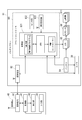
- FIG. 2 is a block diagram showing a functional configuration of the multicopter 91.
- the multicopter 91 is mainly composed of a flight controller 83 that controls the attitude and flight operation of the multicopter 91 in the air, a plurality of rotor blades 911 that generate lift by rotating the multicopter 91, and a pilot (transceiver 81).
- a transmitter / receiver 82 that performs wireless communication with the camera
- a camera 30 as a photographing unit
- a battery 84 that supplies power to them.
- the flight controller 83 includes a control unit 831 that is a microcontroller.
- the control unit 831 includes a CPU that is a central processing unit, a RAM / ROM that is a storage device, and a PWM controller that controls the DC motor 86.
- the DC motor 86 is coupled to each rotary blade 911, and the rotational speed of each DC motor 86 is controlled via an ESC (Electric Speed Controller) 85 in accordance with an instruction from the PWM controller.
- the attitude and movement of the multicopter 91 are controlled by the balance of the rotational speeds of the four rotor blades 911.
- the flight controller 83 includes a sensor group 832 and a GNSS receiver 833, which are connected to the control unit 831.
- the sensor group 832 of the multicopter 91 includes an acceleration sensor, a gyro sensor (angular velocity sensor), an atmospheric pressure sensor, a geomagnetic sensor (electronic compass), and the like.
- the RAM / ROM of the control unit 831 stores a flight control program in which a flight control algorithm during the flight of the multicopter 91 is implemented.
- the control unit 831 can control the attitude and position of the multicopter 91 by the flight control program using information acquired from the sensor group 832.
- the flight operation of the multicopter 91 can be performed manually by the operator via the transceiver 81.
- an autonomous flight program in which a flight plan such as a flight position (GNSS coordinates and altitude) and a flight route is parameterized can be separately implemented to fly autonomously (autopilot).
- the camera 30 receives an instruction from the control unit 831 and takes an image.
- the image captured by the camera 30 is transmitted to the operator-side transceiver 81 via the control unit 831 and the transceiver 82.
- the multi-copter 91 is provided with a separate operation device 40 that can be remotely operated by the operator.
- the operation device 40 includes a control unit 41 that performs calculation / control processing by a CPU, a display unit 42 that can display an image, and an input through which an operator can input parameters and the like.
- a portion 43 is provided.
- a touch panel can be used as a device serving as both the display unit 42 and the input unit 43.
- An image in the camera 30 transmitted via the transceiver 81 is displayed on the display unit 42.
- the input unit 43 is displayed on the display unit 42 when the pilot can manually input the control parameters for controlling the flight of the multicopter 91 as described above, and also when performing flight by autopilot.
- a flight condition such as a flight route R on which the multicopter 91 is to fly autonomously can be designated.
- the operator can also instruct execution of shooting by the camera 30 and change of shooting conditions.
- an information acquisition step (2) a route setting step, and (3) a flight step are performed in this order.
- information acquisition step information that is the basis of control is obtained regarding the state of the ground in the region where the multicopter 91 is to fly.
- route setting step a route for causing the multicopter 91 to fly is set based on the obtained information.
- the multicopter 91 is actually caused to fly based on the set route.
- the concept of “continuous” or “immediately” includes an object (natural object and artificial object) that may affect the flight of the multicopter 91 on the ground in the region where the multicopter 91 is to fly.
- a mode of providing an interval that does not cause a change is also included. The interval is typically allowed to elapse for several hours or even about one day. Further, if the consistency of the above three steps can be maintained, another step such as maintenance of the multicopter 91 may be performed in between. Below, each process is demonstrated.
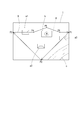
- the multicopter 91 is raised from the ground, the state of the ground is photographed from the sky by the camera 30, and the photographed image I is obtained. Specifically, the operator raises the multicopter 91 using the operation device 40 and instructs the camera 30 to take an image at an appropriate position. At this time, the multicopter 91 stays at a fixed point (hovering), and the camera 30 provided below shoots a state immediately below the vertical direction. As a result, a photographed image I that captures the state of the ground within the field of view F of the camera 30 is obtained. It should be noted that the “fixed point” may include a change in position such that a necessary resolution is obtained in the captured image I.
- the position of the multicopter 91 at the time of photographing the photographed image I may be selected so that the range assumed to fly in the later flight process is included in the photographed image I.
- it may be determined so that the entire range assumed to fly falls within the field of view F of the camera 30.
- the photographed image I photographed by the camera 30 in this step is sent to the operating device 40 via the transceivers 81 and 82. Then, the operator can check on the display unit 42. For example, as shown in FIG. 3, when a region including the houses a1 to a3, the building b, and the river c is captured in the field of view F and photographed, a photographed image I as illustrated in FIG. It is displayed on the display unit 42.
- one large photographed image I may be configured by connecting images photographed immediately below the vertical direction at a plurality of fixed points.
- a photographed image I by three-dimensional mapping may be constructed by photographing while moving the multicopter 91 or changing the photographing direction by the camera 30 and performing appropriate image processing. Then, three-dimensional information including the height of an object that becomes an obstacle to the flight of the multicopter 91 is obtained, and the amount of information that can be used in the subsequent route setting process and flight process increases.
- the currently known three-dimensional mapping method cannot be said to have a sufficiently high quality of the obtained image, and gives significant convenience to the subsequent route setting process and flight process compared to the two-dimensional image. It is hard to be a thing. Therefore, as described above, it is superior from the viewpoint of simplicity to obtain a photographed image I by two-dimensionally photographing at a fixed point immediately below the vertical direction.
- the pilot manually controls the multicopter 91 in the information acquisition process, but this may be performed by autonomous flight. Note that when the multicopter 91 is moved for photographing at a plurality of fixed points or for three-dimensional mapping, there is a possibility that the multicopter 91 exists so as not to contact or collide with an obstacle or the like existing on the ground. It is necessary to fly at a position sufficiently higher than the height of the obstacle or to fly while carefully checking the position of the multicopter 91 by manual operation.
- a flight route R on which the multicopter 91 should fly in the subsequent flight step is set.
- the operator designates a waypoint (reference point) on which the multicopter 91 is to be passed over the captured image I displayed on the display unit 42.
- the altitude at which the multicopter 91 flies is designated, and if there is an operation that the multicopter 91 wants to perform, such as shooting, landing, dropping of an article, etc., those operations are designated.
- the pilot performs the route setting operation, the multicopter 91 may stand in the sky or may return to the ground once.
- the multicopter 91 when specifying the waypoint on the photographed image I, it is necessary to prevent the multicopter 91 from causing a collision, contact, excessive approach or the like to an obstacle existing on the ground.
- the multicopter 91 when the multicopter 91 is assumed to fly at an altitude higher than the houses a1 to a3 but lower than the building b, it is sufficiently separated from the building b in the horizontal direction.
- it is necessary to fly the position or near the building b it is necessary to bypass the building b in the horizontal direction or the vertical direction.
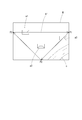
- waypoints P1 to P6 are arranged on the photographed image I, and the flight path R is set.
- the multicopter 91 starts from the first waypoint P1, passes through the two waypoints P2 and P3 in order, and returns to the first waypoint P1.
- the flight path R ′ is set linearly between the waypoint P3 and the waypoint P1, the flight path R ′ overlaps the building b.
- waypoints P4 to P6 are arranged in addition to the waypoints P1 to P3.
- the multicopter 91 can be bypassed, so even if the altitude is lower than that of the building b. It is possible to fly without colliding or contacting the building b (FIG. 5).
- the flight path R is adjusted in the horizontal direction to bypass the building b to avoid collision and contact with the building b, but it passes through the horizontal position where the building b exists or the vicinity thereof. It is possible to avoid collision and contact with the building b by adjusting the flight path R in the vertical direction, for example, by raising the altitude of the flight path R only when it is. Both horizontal and vertical adjustments may be used together.
- the multicopter 91 is actually caused to fly according to the flight path R set above.
- the multicopter 91 performs flight according to the altitude set for each waypoint P1 to P6 in the vertical direction while connecting the waypoints P1 to P6 in the horizontal direction. Further, at each of the waypoints P1 to P6, if there is a designated operation such as shooting, landing, dropping of an article, etc., it is performed.
- the multicopter 91 may start flying according to the flight path R from the state where it has risen and waited in the information acquisition process, or once returned to the ground. You may take off again.
- the pilot may manually control the movement of the multicopter 91 while referring to the flight path R set in the path setting process, but along the set flight path R by the autopilot. It is preferable to fly the multicopter 91 autonomously.
- information on the flight route R and the like set in the route setting step is input from the operating device 40 to the control unit 831 of the multicopter 91 via the transceivers 81 and 82 and reflected in the flight control program. Then, control by autopilot is performed.
- the route setting process the flight conditions such as the flight route R are set in detail and the flight route R is set so as to avoid contact with obstacles such as the building b. If the flight conditions are executed by the autopilot, the multicopter 91 can be made to fly along the flight path R with high accuracy and easily while avoiding a sudden situation such as a collision with an obstacle. It is.
- the waypoints P1 to P6 set on the photographed image I in the route setting step are recognized by the control unit 831 of the multicopter 91 as actual points on the ground, and the multicopter 91 is moved to each recognized point.
- a processing method of converting the positions of the waypoints P1 to P6 on the photographed image I into coordinate values (latitude and longitude) as absolute values on the ground can be considered.
- GNSS signals such as GPS used for managing coordinate values inevitably have a deviation due to time, season, ionospheric state, surrounding environment, etc.
- the waypoints P1 to P6 set on the photographed image I may be recognized not by absolute coordinate values but by the relative positional relationship between the plurality of waypoints P1 to P6.
- the relative positional relationship of the plurality of waypoints P1 to P6 on the photographed image I is uniquely determined as self-contained information, and even the first waypoint (waypoint P1 in the example in the figure) passes correctly.
- each waypoint (P2 to P6) can be traced without being affected by the deviation of the flight position due to external factors such as a GNSS signal.
- positional information not only the relative positional relationship between the waypoints P1 to P6 but also GNSS information may be used supplementarily and used for verification of actual positional control. Particularly in a short-time measurement, the GNSS information does not fluctuate so much that it can be used to verify the accuracy of the relative position.
- the positions of the waypoints P1 to P6 on the photographed image I are converted to positions on the ground. It is preferable to recognize the image pattern on the captured image I and associate it with the actual structure pattern on the ground.
- the image pattern is a shape or color of an object (natural object or artificial object) reflected in an image photographed by the camera 30, for example, the roof or river c of the houses a1 to a3, particularly a shape.
- the image pattern in the photographed image I photographed at 30 and the image pattern in the video photographed in real time by the camera 30 during the flight process may be collated and correlated.
- the relationship between the distance between two points in the obtained image and the distance between two points in the actual photographing target such as the ground is not necessarily the same in each part of the image due to aberration or distortion of the lens. is not.
- the distance in the actual photographing target corresponding to a certain length in the image is often longer at the peripheral portion than at the center portion of the image. Therefore, in order to accurately convert the positions of the waypoints P1 to P6 on the captured image I to positions on the ground, it is necessary to perform correction in consideration of the characteristics of the individual cameras 30.
- the multicopter 91 by recognizing an image as a pattern and associating a pattern at an arbitrary point on the flight path R including the waypoints P1 to P6 on the image with an actual ground pattern, such correction is performed. This is not necessary, and it is possible to control the multicopter 91 to fly accurately along the set flight path R with a simple process.
- the method of using the image pattern as the position reference is a concept called GCP (Ground Control Point), and is also used for topographic surveying. From the viewpoint of controlling the position of the multicopter 91 with higher accuracy, both the recognition based on the image pattern and the recognition of the position information are used together, and the flight path R on the captured image I is actually You may associate with the path
- position information in this case as described above, the relative positional relationship between the waypoints P1 to P6, and further GNSS information can be used.
- the flight path of the multicopter 91 is not set using existing information created in advance such as aerial photographs, but at the time of the information acquisition process. After confirming the ground condition at, the flight path R is immediately determined in the path setting process, and the actual flight is performed along the flight path R in the flight process. This recognizes an object that actually exists on the ground at that time, such as the building b in the above example, and that can interfere with the flight of the multicopter 91, so as to avoid contact and collision with the object, The flight path R can be determined and the multicopter 91 can actually fly.
- the control method including the information acquisition step such a situation is avoided by confirming the flight path R based on information on the ground immediately before the flight.
- the relative positional relationship is used instead of the absolute coordinates of the waypoints P1 to P6.
- the multicopter 91 may further include a distance measuring sensor that measures a distance to a surrounding object.
- the flight path R is set so as to avoid an obstacle on the captured image I in the route setting process.
- the distance to the obstacle may be constantly measured by the distance measuring sensor, and the multicopter 91 may fly while confirming in real time whether contact with the obstacle actually occurs.
- the obstacle can be detected with sufficiently high accuracy without detecting such an obstacle in real time. Object avoidance can be achieved.
- control method As described above, by using the control method according to the present embodiment, even when using an inexpensive multicopter that does not have a distance measuring sensor or has a low performance even if it has a distance measuring sensor, obstacles, etc. It is possible to perform a flight that defines the positional relationship with the object with high accuracy.
- the control method according to this embodiment in which the three steps of the information acquisition process, the route setting process, and the flight process are continuously performed is not limited to avoiding obstacles in the flight process, but is actually performed at the time when the multicopter 91 is flying. It can be used for various applications in which it is effective to grasp the state of the ground. For example, when it is necessary to find a place having a specific state from a wide range and perform some operation on the specific place, a wide range of the shot image I is shot in the information acquisition process, and the shot image I After searching for a place having a specific state in step 1, in the route setting process, the flight route R toward the place is set on the photographed image I, and then the multicopter 91 is caused to fly toward the place in the flight step. Can do.
- the multicopter 91 can be directed to that location.
- the control method according to the present embodiment is useful when the ground state has changed significantly in a short time due to the occurrence of a disaster or the like.
Landscapes
- Engineering & Computer Science (AREA)
- Aviation & Aerospace Engineering (AREA)
- Physics & Mathematics (AREA)
- General Physics & Mathematics (AREA)
- Remote Sensing (AREA)
- Radar, Positioning & Navigation (AREA)
- Automation & Control Theory (AREA)
- Mechanical Engineering (AREA)
- Control Of Position, Course, Altitude, Or Attitude Of Moving Bodies (AREA)
- Navigation (AREA)
Priority Applications (2)
| Application Number | Priority Date | Filing Date | Title |
|---|---|---|---|
| US15/768,785 US20180305012A1 (en) | 2015-10-16 | 2016-10-07 | Method for controlling small-size unmanned aerial vehicle |
| AU2016339451A AU2016339451B2 (en) | 2015-10-16 | 2016-10-07 | Method for controlling small-size unmanned aerial vehicle |
Applications Claiming Priority (2)
| Application Number | Priority Date | Filing Date | Title |
|---|---|---|---|
| JP2015204303A JP6390013B2 (ja) | 2015-10-16 | 2015-10-16 | 小型無人飛行機の制御方法 |
| JP2015-204303 | 2015-10-16 |
Publications (1)
| Publication Number | Publication Date |
|---|---|
| WO2017065103A1 true WO2017065103A1 (ja) | 2017-04-20 |
Family
ID=58518154
Family Applications (1)
| Application Number | Title | Priority Date | Filing Date |
|---|---|---|---|
| PCT/JP2016/079915 Ceased WO2017065103A1 (ja) | 2015-10-16 | 2016-10-07 | 小型無人飛行機の制御方法 |
Country Status (4)
| Country | Link |
|---|---|
| US (1) | US20180305012A1 (https=) |
| JP (1) | JP6390013B2 (https=) |
| AU (1) | AU2016339451B2 (https=) |
| WO (1) | WO2017065103A1 (https=) |
Cited By (3)
| Publication number | Priority date | Publication date | Assignee | Title |
|---|---|---|---|---|
| WO2019106714A1 (ja) * | 2017-11-28 | 2019-06-06 | 株式会社自律制御システム研究所 | 無人航空機、無人航空機の飛行制御装置、無人航空機の飛行制御方法、及びプログラム |
| JP2021057078A (ja) * | 2020-12-24 | 2021-04-08 | 株式会社自律制御システム研究所 | 無人航空機、無人航空機の飛行制御装置、無人航空機の飛行制御方法、及びプログラム |
| JPWO2025079128A1 (https=) * | 2023-10-10 | 2025-04-17 |
Families Citing this family (20)
| Publication number | Priority date | Publication date | Assignee | Title |
|---|---|---|---|---|
| US11150089B2 (en) * | 2015-12-31 | 2021-10-19 | Skydio, Inc. | Unmanned aerial vehicle control point selection system |
| US10825345B2 (en) * | 2017-03-09 | 2020-11-03 | Thomas Kenji Sugahara | Devices, methods and systems for close proximity identification of unmanned aerial systems |
| JP6903500B2 (ja) * | 2017-06-28 | 2021-07-14 | 株式会社クボタ | 農業支援システム |
| US10387727B2 (en) | 2017-09-13 | 2019-08-20 | Wing Aviation Llc | Backup navigation system for unmanned aerial vehicles |
| WO2019189381A1 (ja) * | 2018-03-30 | 2019-10-03 | 株式会社ニコン | 移動体、制御装置、および制御プログラム |
| US12033516B1 (en) | 2018-09-22 | 2024-07-09 | Pierce Aerospace Incorporated | Systems and methods for remote identification of unmanned aircraft systems |
| WO2020060573A1 (en) | 2018-09-22 | 2020-03-26 | Pierce Aerospace, Llc | Systems and methods of identifying and managing remotely piloted and piloted air traffic |
| JP2020056696A (ja) * | 2018-10-02 | 2020-04-09 | パイオニア株式会社 | 飛行ルート処理装置、飛行ルート処理方法、及びプログラム |
| JP2020056694A (ja) * | 2018-10-02 | 2020-04-09 | パイオニア株式会社 | 情報処理装置、着陸候補地点送信装置、データ構造、情報処理方法、及びプログラム |
| JP7345153B2 (ja) * | 2018-12-26 | 2023-09-15 | 学校法人立命館 | 飛翔体の地理座標推定装置、地理座標推定システム、地理座標推定方法、及びコンピュータプログラム |
| JP7253315B2 (ja) | 2019-01-29 | 2023-04-06 | 株式会社Subaru | 航空機の飛行支援システム、航空機の飛行支援プログラム及び航空機 |
| JP7377642B2 (ja) * | 2019-08-05 | 2023-11-10 | 株式会社フジタ | 複数台の車両の管理装置 |
| JP7349860B2 (ja) * | 2019-09-20 | 2023-09-25 | 株式会社フジタ | 複数台の車両の管理システム |
| WO2021064982A1 (ja) * | 2019-10-04 | 2021-04-08 | 株式会社トラジェクトリー | 情報処理装置および情報処理方法 |
| JP7384042B2 (ja) * | 2020-01-09 | 2023-11-21 | 三菱電機株式会社 | 飛行ルート学習装置、飛行ルート決定装置及び飛行装置 |
| WO2021217346A1 (zh) * | 2020-04-27 | 2021-11-04 | 深圳市大疆创新科技有限公司 | 信息处理方法、信息处理装置和可移动设备 |
| WO2022070851A1 (ja) * | 2020-09-30 | 2022-04-07 | 株式会社Clue | 方法、システムおよびプログラム |
| CN113791631A (zh) * | 2021-09-09 | 2021-12-14 | 常州希米智能科技有限公司 | 一种基于北斗的无人机定位飞行控制方法和装置 |
| WO2025126898A1 (ja) * | 2023-12-15 | 2025-06-19 | ソニーグループ株式会社 | 情報処理方法、情報処理装置、及びコンピュータプログラム |
| CN119247976B (zh) * | 2024-09-24 | 2025-11-18 | 广州极飞科技股份有限公司 | 全场景自适应飞行方法、装置、设备及存储介质 |
Citations (3)
| Publication number | Priority date | Publication date | Assignee | Title |
|---|---|---|---|---|
| JP2002211494A (ja) * | 2001-01-17 | 2002-07-31 | Todaka Seisakusho:Kk | 無人ヘリコプタ用飛行計画装置 |
| JP2014040231A (ja) * | 2012-07-13 | 2014-03-06 | Honeywell Internatl Inc | 自主的な空間飛行計画および仮想空間抑制システム |
| JP2014063411A (ja) * | 2012-09-24 | 2014-04-10 | Casio Comput Co Ltd | 遠隔制御システム、制御方法、及び、プログラム |
Family Cites Families (3)
| Publication number | Priority date | Publication date | Assignee | Title |
|---|---|---|---|---|
| US7970532B2 (en) * | 2007-05-24 | 2011-06-28 | Honeywell International Inc. | Flight path planning to reduce detection of an unmanned aerial vehicle |
| JP2009031884A (ja) * | 2007-07-25 | 2009-02-12 | Toyota Motor Corp | 自律移動体、自律移動体におけるマップ情報作成方法および自律移動体における移動経路特定方法 |
| US20100286859A1 (en) * | 2008-11-18 | 2010-11-11 | Honeywell International Inc. | Methods for generating a flight plan for an unmanned aerial vehicle based on a predicted camera path |
-
2015
- 2015-10-16 JP JP2015204303A patent/JP6390013B2/ja active Active
-
2016
- 2016-10-07 WO PCT/JP2016/079915 patent/WO2017065103A1/ja not_active Ceased
- 2016-10-07 US US15/768,785 patent/US20180305012A1/en not_active Abandoned
- 2016-10-07 AU AU2016339451A patent/AU2016339451B2/en not_active Ceased
Patent Citations (3)
| Publication number | Priority date | Publication date | Assignee | Title |
|---|---|---|---|---|
| JP2002211494A (ja) * | 2001-01-17 | 2002-07-31 | Todaka Seisakusho:Kk | 無人ヘリコプタ用飛行計画装置 |
| JP2014040231A (ja) * | 2012-07-13 | 2014-03-06 | Honeywell Internatl Inc | 自主的な空間飛行計画および仮想空間抑制システム |
| JP2014063411A (ja) * | 2012-09-24 | 2014-04-10 | Casio Comput Co Ltd | 遠隔制御システム、制御方法、及び、プログラム |
Cited By (6)
| Publication number | Priority date | Publication date | Assignee | Title |
|---|---|---|---|---|
| WO2019106714A1 (ja) * | 2017-11-28 | 2019-06-06 | 株式会社自律制御システム研究所 | 無人航空機、無人航空機の飛行制御装置、無人航空機の飛行制御方法、及びプログラム |
| JPWO2019106714A1 (ja) * | 2017-11-28 | 2020-11-19 | 株式会社自律制御システム研究所 | 無人航空機、無人航空機の飛行制御装置、無人航空機の飛行制御方法、及びプログラム |
| JP2021057078A (ja) * | 2020-12-24 | 2021-04-08 | 株式会社自律制御システム研究所 | 無人航空機、無人航空機の飛行制御装置、無人航空機の飛行制御方法、及びプログラム |
| JP7184381B2 (ja) | 2020-12-24 | 2022-12-06 | 株式会社Acsl | 無人航空機、無人航空機の飛行制御装置、無人航空機の飛行制御方法、及びプログラム |
| JPWO2025079128A1 (https=) * | 2023-10-10 | 2025-04-17 | ||
| WO2025079128A1 (ja) * | 2023-10-10 | 2025-04-17 | 三菱電機株式会社 | 情報処理装置、制御方法、及び制御プログラム |
Also Published As
| Publication number | Publication date |
|---|---|
| US20180305012A1 (en) | 2018-10-25 |
| AU2016339451B2 (en) | 2019-06-20 |
| JP6390013B2 (ja) | 2018-09-19 |
| JP2017076302A (ja) | 2017-04-20 |
| AU2016339451A1 (en) | 2018-05-24 |
Similar Documents
| Publication | Publication Date | Title |
|---|---|---|
| JP6390013B2 (ja) | 小型無人飛行機の制御方法 | |
| JP6055274B2 (ja) | 航空写真測定方法及び航空写真測定システム | |
| US8666571B2 (en) | Flight control system for flying object | |
| CN110062919B (zh) | 递送车辆的放下地点规划 | |
| JP6132981B2 (ja) | 飛行機の状態をリアルタイムに修正する方法および装置 | |
| EP2772725B1 (en) | Aerial Photographing System | |
| EP2538298A1 (en) | Method for acquiring images from arbitrary perspectives with UAVs equipped with fixed imagers | |
| WO2017116841A1 (en) | Unmanned aerial vehicle inspection system | |
| JP6934116B1 (ja) | 航空機の飛行制御を行う制御装置、及び制御方法 | |
| US20180005534A1 (en) | Autonomous navigation of an unmanned aerial vehicle | |
| KR102467855B1 (ko) | 자율항법지도를 설정하는 방법 및 무인비행체가 자율항법지도에 기초하여 자율 비행하는 방법 및 이를 구현하는 시스템 | |
| CN104007767A (zh) | 无人机空间导航方法、无人机控制系统及控制装置 | |
| JP2019032234A (ja) | 表示装置 | |
| JP6957304B2 (ja) | 架線撮影システム及び架線撮影方法 | |
| JP7031997B2 (ja) | 飛行体システム、飛行体、位置測定方法、プログラム | |
| CN106483969A (zh) | 一种多旋翼视觉循迹无人机 | |
| WO2021237462A1 (zh) | 无人飞行器的限高方法、装置、无人飞行器及存储介质 | |
| KR20220086479A (ko) | 항공기 센서 시스템 동기화 | |
| WO2020062356A1 (zh) | 控制方法、控制装置、无人飞行器的控制终端 | |
| JP6973829B2 (ja) | 圃場撮影用カメラ | |
| US20220230550A1 (en) | 3d localization and mapping systems and methods | |
| EP3331758B1 (en) | An autonomous vehicle control system | |
| CN110892353A (zh) | 控制方法、控制装置、无人飞行器的控制终端 | |
| JP2019168229A (ja) | Uavを用いた標点マーキングシステム | |
| KR20230126649A (ko) | 드론 제어 방법 및 그 장치 |
Legal Events
| Date | Code | Title | Description |
|---|---|---|---|
| 121 | Ep: the epo has been informed by wipo that ep was designated in this application |
Ref document number: 16855357 Country of ref document: EP Kind code of ref document: A1 |
|
| DPE1 | Request for preliminary examination filed after expiration of 19th month from priority date (pct application filed from 20040101) | ||
| WWE | Wipo information: entry into national phase |
Ref document number: 15768785 Country of ref document: US |
|
| NENP | Non-entry into the national phase |
Ref country code: DE |
|
| ENP | Entry into the national phase |
Ref document number: 2016339451 Country of ref document: AU Date of ref document: 20161007 Kind code of ref document: A |
|
| 122 | Ep: pct application non-entry in european phase |
Ref document number: 16855357 Country of ref document: EP Kind code of ref document: A1 |