WO2017065045A1 - 保護制御装置 - Google Patents
保護制御装置 Download PDFInfo
- Publication number
- WO2017065045A1 WO2017065045A1 PCT/JP2016/079374 JP2016079374W WO2017065045A1 WO 2017065045 A1 WO2017065045 A1 WO 2017065045A1 JP 2016079374 W JP2016079374 W JP 2016079374W WO 2017065045 A1 WO2017065045 A1 WO 2017065045A1
- Authority
- WO
- WIPO (PCT)
- Prior art keywords
- collision
- threshold
- bicycle
- low output
- output area
- Prior art date
- Legal status (The legal status is an assumption and is not a legal conclusion. Google has not performed a legal analysis and makes no representation as to the accuracy of the status listed.)
- Ceased
Links
Images


Classifications
-
- B—PERFORMING OPERATIONS; TRANSPORTING
- B60—VEHICLES IN GENERAL
- B60R—VEHICLES, VEHICLE FITTINGS, OR VEHICLE PARTS, NOT OTHERWISE PROVIDED FOR
- B60R21/00—Arrangements or fittings on vehicles for protecting or preventing injuries to occupants or pedestrians in case of accidents or other traffic risks
- B60R21/34—Protecting non-occupants of a vehicle, e.g. pedestrians
-
- B—PERFORMING OPERATIONS; TRANSPORTING
- B60—VEHICLES IN GENERAL
- B60R—VEHICLES, VEHICLE FITTINGS, OR VEHICLE PARTS, NOT OTHERWISE PROVIDED FOR
- B60R21/00—Arrangements or fittings on vehicles for protecting or preventing injuries to occupants or pedestrians in case of accidents or other traffic risks
- B60R21/01—Electrical circuits for triggering passive safety arrangements, e.g. airbags, safety belt tighteners, in case of vehicle accidents or impending vehicle accidents
- B60R21/013—Electrical circuits for triggering passive safety arrangements, e.g. airbags, safety belt tighteners, in case of vehicle accidents or impending vehicle accidents including means for detecting collisions, impending collisions or roll-over
- B60R21/0136—Electrical circuits for triggering passive safety arrangements, e.g. airbags, safety belt tighteners, in case of vehicle accidents or impending vehicle accidents including means for detecting collisions, impending collisions or roll-over responsive to actual contact with an obstacle, e.g. to vehicle deformation, bumper displacement or bumper velocity relative to the vehicle
-
- B—PERFORMING OPERATIONS; TRANSPORTING
- B60—VEHICLES IN GENERAL
- B60R—VEHICLES, VEHICLE FITTINGS, OR VEHICLE PARTS, NOT OTHERWISE PROVIDED FOR
- B60R19/00—Wheel guards; Radiator guards, e.g. grilles; Obstruction removers; Fittings damping bouncing force in collisions
- B60R19/02—Bumpers, i.e. impact receiving or absorbing members for protecting vehicles or fending off blows from other vehicles or objects
- B60R19/48—Bumpers, i.e. impact receiving or absorbing members for protecting vehicles or fending off blows from other vehicles or objects combined with, or convertible into, other devices or objects, e.g. bumpers combined with road brushes, bumpers convertible into beds
- B60R19/483—Bumpers, i.e. impact receiving or absorbing members for protecting vehicles or fending off blows from other vehicles or objects combined with, or convertible into, other devices or objects, e.g. bumpers combined with road brushes, bumpers convertible into beds with obstacle sensors of electric or electronic type
-
- B—PERFORMING OPERATIONS; TRANSPORTING
- B60—VEHICLES IN GENERAL
- B60R—VEHICLES, VEHICLE FITTINGS, OR VEHICLE PARTS, NOT OTHERWISE PROVIDED FOR
- B60R21/00—Arrangements or fittings on vehicles for protecting or preventing injuries to occupants or pedestrians in case of accidents or other traffic risks
- B60R21/01—Electrical circuits for triggering passive safety arrangements, e.g. airbags, safety belt tighteners, in case of vehicle accidents or impending vehicle accidents
- B60R21/013—Electrical circuits for triggering passive safety arrangements, e.g. airbags, safety belt tighteners, in case of vehicle accidents or impending vehicle accidents including means for detecting collisions, impending collisions or roll-over
- B60R21/0134—Electrical circuits for triggering passive safety arrangements, e.g. airbags, safety belt tighteners, in case of vehicle accidents or impending vehicle accidents including means for detecting collisions, impending collisions or roll-over responsive to imminent contact with an obstacle, e.g. using radar systems
-
- B—PERFORMING OPERATIONS; TRANSPORTING
- B60—VEHICLES IN GENERAL
- B60R—VEHICLES, VEHICLE FITTINGS, OR VEHICLE PARTS, NOT OTHERWISE PROVIDED FOR
- B60R21/00—Arrangements or fittings on vehicles for protecting or preventing injuries to occupants or pedestrians in case of accidents or other traffic risks
- B60R21/34—Protecting non-occupants of a vehicle, e.g. pedestrians
- B60R2021/343—Protecting non-occupants of a vehicle, e.g. pedestrians using deformable body panel, bodywork or components
Definitions
- the present disclosure relates to a protection control device that controls the operation of a protection device for protecting a person colliding with a vehicle.
- the front end portion includes a corner portion.
- Patent Document 1 a conventional system for operating a protection device for protecting pedestrians that collide with vehicles when primary collisions with pedestrians are detected.
- Patent Document 1 a conventional system for operating a protection device for protecting pedestrians that collide with vehicles when primary collisions with pedestrians are detected.
- Patent Document 1 a pop-up hood device that lifts the rear of the hood in addition to a windshield, an airbag that is deployed in various areas such as a pillar portion, a cowl top, etc. is there.
- a threshold value (hereinafter referred to as an operation threshold value) for operating the protection device is set in advance for the output value of the collision sensor for detecting the primary collision.
- the apparatus (henceforth a protection control apparatus) which controls operation
- the impact of the collision is distributed along the shape of the corner portion. Specifically, since the impact of the collision is released in the lateral direction of the vehicle, the force acting in the rear direction of the vehicle is reduced. As a result, the output value of the collision sensor tends to be smaller than when the vehicle collides near the center in the vehicle width direction.
- back direction here refers to the direction from the front end to the rear end of the vehicle
- side direction refers to the direction parallel to the vehicle width direction and from the inside to the outside of the vehicle.
- the collision position When the position where the pedestrian collides at the front end portion (hereinafter referred to as the collision position) is a low output area, the output of the collision sensor may not reach the operation threshold value and the protection device may not operate. Can occur. Naturally, from the viewpoint of pedestrian protection, it is preferable that the protection device operates.
- An object of the present disclosure is to provide a protection control device that can reduce the possibility that the protection device does not operate due to the collision position at the front end of the vehicle.
- a protection control device is used in a vehicle provided with a protection device for protecting a person colliding with the vehicle, and detects a collision with another object at a front end portion of the vehicle.
- An output value acquisition unit that acquires an output value of a collision sensor, an object recognition unit that acquires information about an object existing in front of the vehicle, and a target that collides with the vehicle based on information acquired by the object recognition unit
- a collision target identifying unit that identifies a collision target, a collision position acquisition unit that acquires a collision position where the collision target collides at the front end of the vehicle, and an output value acquired by the output value acquisition unit is a protection device
- An operation determining unit that operates the protection device when the value is larger than an operation threshold value for operating the device.
- the collision determination acquired by the collision determination unit is not a low output area where the output value of the collision sensor tends to be suppressed compared to other parts of the front end.
- the collision position acquired by the collision position acquisition unit is a low output area while a predetermined default threshold is adopted as the operation threshold, a threshold for the low output area smaller than the default threshold is set as the operation threshold. adopt.
- the collision position acquisition unit acquires the collision position in the front end of the vehicle. Then, when the acquired collision position is a low output area, the motion determination unit selects a low output area protection device smaller than a default threshold used when the collision position is not a low output area. It is determined whether or not to operate.
- the protection device works. Therefore, according to the above configuration, it is possible to reduce the possibility that the protection device does not operate due to the collision position at the front end.
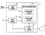
- FIG. 1 is a block diagram illustrating a schematic configuration of a protection device control system according to an embodiment of the present disclosure.
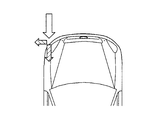
- FIG. 2 is a diagram for explaining a low output area.
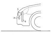
- FIG. 3 is a diagram for explaining the low output area.
- FIG. 4 is a diagram showing a portion set in the low output area.
- FIG. 5 is a block diagram showing a schematic configuration of the ECU.
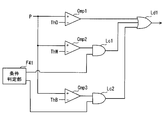
- FIG. 6 is a block diagram illustrating an example of the configuration of the operation determination unit.
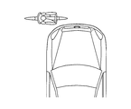
- FIG. 7 is a conceptual diagram showing a bicycle in a lateral orientation with respect to the host vehicle.
- FIG. 1 is a block diagram illustrating a schematic configuration of a protection device control system according to an embodiment of the present disclosure.
- FIG. 2 is a diagram for explaining a low output area.
- FIG. 3 is a diagram for explaining the low output area.
- FIG. 4 is a diagram showing a portion set in the low output area.
- FIG. 5 is a block diagram showing a schematic configuration of
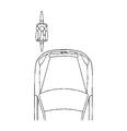
- FIG. 8 is a conceptual diagram showing a bicycle in a vertical posture with respect to the host vehicle.
- FIG. 9 is a block diagram illustrating an example of the configuration of the operation determination unit in the second modification.
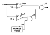
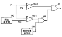
- FIG. 10 is a block diagram illustrating an example of the configuration of the operation determination unit in the third modification.
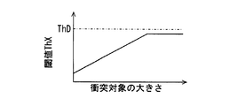
- FIG. 11 is a conceptual diagram illustrating a correspondence relationship between the size of the collision target and the threshold for the low output area.
- FIG. 1 is a diagram illustrating an example of a schematic configuration of a protection device control system 100 according to the present embodiment.
- This protection device control system 100 is mounted on a vehicle.
- the vehicle on which the protection device control system 100 is mounted is assumed to be the host vehicle.
- This protection device control system 100 is a system for protecting a person colliding with the own vehicle. As a person to be protected here, for example, a pedestrian or a bicycle occupant is assumed. As another mode, the protection device control system 100 may be a mode in which an occupant of a two-wheeled mobile body other than a bicycle, such as a motorbike or a motorcycle, is assumed to be protected.
- the protection device control system 100 in this embodiment includes an electronic control unit (ECU) 1, a camera 2, a collision sensor 3, and an external protection device 4 as shown in FIG.
- the ECU 1 is connected to each of the camera 2, the collision sensor 3, and the external protection device 4 via a local area network built in the vehicle.
- the ECU 1 is configured as a normal computer, and includes a CPU 11, a RAM 12, a ROM 13, an I / O, and a bus line that connects these configurations.
- the RAM 12 functions as a main storage device (so-called memory) for the CPU 11.
- the ROM 13 functions as an auxiliary storage device (so-called storage).
- the ROM 13 stores a program (hereinafter referred to as a control program) for causing a normal computer to function as the ECU 1 in the present embodiment.
- a control program for causing a normal computer to function as the ECU 1 in the present embodiment.
- the above-described control program only needs to be stored in a non-transitional physical recording medium such as a flash memory or a ROM.
- the execution of the control program by the CPU 11 corresponds to the execution of a method corresponding to the control program.
- the ROM 13 includes a portion (hereinafter referred to as a low output area) in which the output value of the collision sensor 3 is less likely to be output compared to other portions even if the same impact is applied to the front end portion of the host vehicle.
- the indicated data is stored.
- the low output area will be described later separately.
- the front end portion includes a corner portion.
- the ECU 1 controls the operation of the external protection device 4 based on signals input from the camera 2 and the collision sensor 3.
- the ECU 1 corresponds to a protection control device. Details of the functions of the ECU 1 will be described after the camera 2, the collision sensor 3, and the external protection device 4 are described.
- the camera 2 is an optical camera, and for example, a CMOS camera or a CCD camera can be used.
- the camera 2 should just be installed in the windshield upper end part vicinity (for example, vicinity of a room mirror) so that the predetermined range ahead of the own vehicle may be image
- Image data taken by the camera 2 is sequentially provided to the ECU 1.
- the installation position of the camera 2 is not limited to the vicinity of the rearview mirror, but may be attached to a position that does not block the driver's view of the front of the vehicle.
- the camera 2 may be an infrared camera, a near-infrared camera, or the like.
- the camera 2 may be a stereo camera.
- the collision sensor 3 is a sensor for detecting a first collision (so-called primary collision) between a front end portion of the own vehicle and an object other than the own vehicle.
- the collision sensor 3 is disposed along the vehicle width direction at the front end of the vehicle, and outputs a value corresponding to the magnitude of the impact of the collision to the ECU 1.
- the collision sensor 3 is realized by using a pressure chamber disposed substantially parallel to the front bumper and a pressure sensor for sensing the pressure in the pressure chamber. That is, the collision sensor 3 outputs an amount of change in pressure accompanying the deformation of the pressure chamber as an output value.
- the collision sensor 3 is not limited to a pressure sensor.
- it may be of a type that detects a collision based on a change in the amount of light output from an optical fiber arranged along the vehicle body.
- An acceleration sensor may be used as the collision sensor 3.
- the external protection device 4 is a device for protecting a person colliding with the host vehicle.
- Examples of the external protection device 4 include a pop-up hood device that instantaneously lifts the rear of an engine hood (in other words, a hood), an external airbag that is deployed in a predetermined area outside the vehicle, and the like.
- the external protection device 4 operates based on an instruction from the ECU 1.
- the external protection device 4 corresponds to a protection device.
- the low output area registered in the ROM 13 will be described with reference to FIGS.
- the low output area is a portion in which the output value of the collision sensor 3 is less likely to be output compared to other portions of the front end portion of the host vehicle.
- the corner portion corresponds to the low output area.
- the impact of the collision is distributed along the shape of the corner portion. That is, since the impact of the collision is released in the lateral direction of the vehicle, the force acting in the rear direction of the vehicle is reduced. As a result, when a pedestrian or the like collides at the corner portion of the front end, the output value tends to be smaller than when the vehicle collides near the center in the vehicle width direction.
- the back direction here refers to the direction from the front end to the rear end of the vehicle
- the side direction refers to the direction parallel to the vehicle width direction and from the inside to the outside of the vehicle.
- the white arrow in FIG. 2 conceptually represents the magnitude of the impact applied to the vehicle
- the hatched arrow represents the component transmitted in the rear direction and the side of the impact applied to the corner portion.
- the components transmitted to the rear are conceptually represented.
- the corner area even in areas other than the corner area, it may be a low output area.
- the member inhibits deformation of the vehicle body due to the impact of the collision and propagation of the impact to the collision sensor 3. 3 is difficult to output.
- a portion where such a relatively hard member that hinders deformation of the vehicle body is disposed in the vicinity of the collision detection sensor can also be a low output area.
- a distance measuring sensor 5 such as a millimeter wave radar is fixed to the radiator 6 so as to be located near the pressure chamber 31 constituting the collision sensor 3 as shown in FIG. There may be.
- the distance measuring sensor 5 is arranged in the vicinity of the pressure chamber 31 in this way, the distance measuring sensor 5 supported by the radiator 6 causes a factor (hereinafter referred to as “impact propagation” to the pressure chamber 31). May act as an inhibitor).
- the distance measuring sensor 5 when the distance measuring sensor 5 is disposed on the vehicle front end side with respect to the pressure chamber 31 constituting the collision sensor 3, the distance measuring sensor 5 tends to act as an obstacle.
- the member acting as an obstacle is not limited to the distance measuring sensor 5.
- the headlamp, the fog lamp, and the like can also become obstacles.
- the portion of the vehicle front end that becomes the low output area is determined by the characteristics (hereinafter referred to as vehicle characteristics) for each vehicle model, such as the shape of the vehicle front end and the arrangement of parts at the vehicle front end.
- the left corner portion Z1, the central portion Z2, and the right corner portion Z3 are set as low output areas among the front end portions as shown in FIG.
- the left corner portion Z1 here is a region from a leftmost portion in the vehicle width direction to a central distance within a certain distance (for example, 0.4 m).
- the right corner portion Z3 is a region from a portion on the rightmost side in the vehicle width direction to a center distance that is within a certain distance (for example, 0.4 m).
- the central portion Z2 is a region that is within a certain distance (for example, 0.1 m) from the center in the vehicle width direction to the left and right.
- the low output area at the front end may be represented by coordinates in a plane coordinate system (XY coordinate system) in which the vehicle longitudinal direction is the X axis and the vehicle width direction is the Y axis.
- the origin of the XY coordinate system may be, for example, the center point in the vehicle width direction in the front end portion of the vehicle.
- the X-axis has a back direction as the positive direction
- the Y-axis has a positive direction from the left side to the right side of the vehicle.
- the ECU 1 includes a collision detection unit F1, an image recognition unit F2, a collision target information acquisition unit F3, and a functional block realized by the CPU 11 executing a control program stored in the ROM 13.
- the operation determination unit F4 is provided.
- the collision target information acquisition part F3 is provided with the collision target specific
- Each of the various functional blocks provided in the ECU 1 may be realized by hardware by one or a plurality of ICs. In the present embodiment, as an example, a part of the operation determination unit F4 is realized by hardware.
- the collision detection unit F1 acquires the output value of the collision sensor 3, and provides the output value to the operation determination unit F4. This collision detection unit F1 corresponds to an output value acquisition unit.
- the collision detection unit F1 determines whether the output value of the collision sensor 3 has collided with an object other than the host vehicle and the front end of the host vehicle (that is, primary collision). If it is equal to or greater than the collision determination threshold, it is determined that a primary collision has occurred. And the collision detection signal which shows that the collision in the front-end part had arisen is provided to the collision object information acquisition part F3.
- the image recognition unit F2 analyzes the image data input from the camera 2, and performs detection of an object preset as a detection target and identification of the type. For example, the image recognition unit F2 performs known image processing such as edge detection on the image data, and extracts the contours of all objects included in the image. Then, by performing pattern matching processing on the image data that has undergone image processing, an object that is a detection target is detected and the type of the object is specified.
- the object to be detected may be designed appropriately.
- a pedestrian and a bicycle on which an occupant is riding (hereinafter, a bicycle with an occupant) are registered as detection targets.
- Setting a bicycle with an occupant as a detection target corresponds to setting a bicycle occupant as a detection target.
- the object to be detected is not limited to that described above.
- Other types of moving bodies such as a motorbike, a motorcycle, an automobile, and the like may be set as detection targets.
- a structure such as a utility pole may also be set as a detection target.
- image recognition data used for the image recognition unit F2 to detect these detection target objects from the image data
- the image recognition data corresponds to data representing the shape pattern of an object to be detected, for example.
- the image recognition unit F2 estimates the relative position between the detected object and the host vehicle from the position and size of the detected object (hereinafter, detected object) in the image data. Furthermore, the object once detected is tracked with the aid of a well-known object tracking method. Thereby, the relative moving direction and moving speed of the detected object are estimated from the degree of change in the position and size of the same detected object between a plurality of consecutive frames. Note that the relative position of the detected object with respect to the host vehicle may be represented by the coordinates of the XY coordinate system described above.
- the relative position may be estimated based on the difference in position of the same object in each image data.
- the result of the image recognition processing by the image recognition unit F2 is provided to the collision target information acquisition unit F3.
- the image recognition unit F2 corresponds to the object recognition unit.
- the collision target information acquisition unit F3 acquires the result of the image recognition processing by the image recognition unit F2 as information about the object existing in front of the host vehicle. Specifically, the relative position and relative speed for each detected object, the type as a moving object, and the like are acquired.
- the collision target information acquisition unit F3 identifies an object (hereinafter referred to as a collision target) that has collided with the host vehicle based on the result of the image recognition processing by the image recognition unit F2.
- the collision target identification unit F31 and the collision position acquisition unit F32 included in the collision target information acquisition unit F3 are functional blocks for acquiring various information about the collision target.
- the collision target identification unit F31 identifies a collision target based on information about objects existing ahead of the host vehicle that are sequentially collected when the collision detection unit F1 detects the occurrence of a collision.
- the collision target specifying unit F31 determines that, among the detection objects existing in front of the host vehicle, the detection object present at the position closest to the host vehicle at the time of the collision is the collision target.
- the collision occurrence time point includes immediately before the collision (for example, 0.5 seconds before).
- the object closest to the host vehicle is at a certain distance (for example, 3 m) or more from the host vehicle, there is a possibility that it is in contact with an object other than the detected object. Therefore, when the distance between the detected object present at the position closest to the host vehicle and the host vehicle is a certain distance or more, it is determined that the collision target is an undetected object.
- production of the collision it is not restricted to this.
- an object whose collision surplus time as a remaining time until it collides with the host vehicle determined from the relative speed is less than a certain time (for example, 0.5 seconds)
- the target of collision may be determined at the point in time when That is, the collision target may be not only an object that has actually undergone a primary collision, but also an object that will undergo a primary collision in the future.
- the collision position acquisition unit F32 specifies a position (hereinafter referred to as a collision position) where the collision target collides at the front end of the host vehicle based on the recognition result of the image recognition unit F2. Specifically, the relative position of the collision target at the time when the collision is detected is acquired as the collision position.
- the collision position may be represented by coordinates in the XY coordinate system.
- the collision position acquisition unit F32 may estimate the collision position by correcting the relative position of the collision target immediately before the collision using the relative speed and the relative movement direction at that time.
- the collision position acquisition unit F32 acquires the position of the center of gravity of the bicycle with the occupant as the collision target as the collision position. That's fine.
- the center-of-gravity position in a bicycle with a passenger may be a position that is intermediate between the front and rear wheels of the bicycle.
- the position on which the driver is riding (for example, the position of the driver's waist) may be regarded as the position of the center of gravity of the bicycle with the occupant.
- the position of the saddle may be regarded as a collision position.
- the type of the collision target moving body specified by the collision target specifying unit F31 and the collision position acquired by the collision position acquisition unit F32 are provided to the operation determination unit F4.
- the operation determination unit F4 determines whether or not the external protection device 4 should be operated based on the output value P provided from the collision detection unit F1. When it is determined that the external protection device 4 should be operated, an operation instruction signal for instructing the external protection device 4 to operate is output and operated.
- three types of threshold values a default threshold value, a pedestrian threshold value, and a bicycle threshold value, are prepared, and the motion determination unit F4 is configured according to the collision position and the type of the moving object as a collision target. Any one of these three threshold values is adopted as the operation threshold value. Then, when the output value P exceeds the threshold adopted as the operation threshold, it is determined that the external protection device 4 should be operated.
- the default threshold ThD is a threshold used when the collision position is outside the low output area.
- the default threshold ThD may be designed as appropriate.
- the default threshold ThD is at least larger than the above-described collision detection threshold, and further does not exceed a collision with an object that is sufficiently lighter than a human, such as a small animal (for example, a cat) or a road cone.
- a human such as a small animal (for example, a cat) or a road cone.
- the default threshold ThD may be determined by an actual test, a simulation, or the like (hereinafter, an actual test) using a dummy doll or the like.
- the pedestrian threshold value ThW is a threshold value that is assumed when a pedestrian collides with a low output area.
- the pedestrian threshold ThW may be the minimum value of the output value P that can be output by the collision sensor 3 when a pedestrian collides with the low output area.
- the minimum value of the output value P that can be output by the collision sensor 3 when a pedestrian collides with the low output area may be determined by an actual test or the like.
- the pedestrian threshold ThW is set smaller than the default threshold ThD.
- the bicycle threshold ThB is a threshold assuming a case where a bicycle with a passenger collides with a low output area.
- the bicycle threshold ThB may be a minimum value of the output value P that can be output by the collision sensor 3 when a bicycle with a passenger collides with the low output area.
- the minimum value of the output value P that can be output by the collision sensor 3 when a bicycle with a passenger collides with the low output area may be determined by an actual test or the like.
- the bicycle threshold ThB is set smaller than the pedestrian threshold ThW.
- FIG. 6 shows an example of a configuration for the operation determination unit F4 to determine whether the external protection device 4 operates properly using an operation threshold corresponding to the collision position and the type of the collision target moving body.
- the operation determination unit F4 includes a condition determination unit F41, comparators Cmp1 to Cmp3, AND elements Lc1 to Lc2, and an OR element Ld1.
- Each of the comparators Cmp1 to Cmp3 includes a plus side input terminal and a minus side input terminal.
- the comparators Cmp1 to Cmp3 are high level.
- An element or circuit that outputs a signal (in other words, 1 in a positive logic circuit).
- the output value P of the collision sensor 3 is input to the plus side input terminals of the comparators Cmp1 to Cmp3.
- the voltage corresponding to the default threshold ThD is input to the negative side input terminal of the comparator Cmp1. That is, the comparator Cmp1 is configured to compare the output value P of the collision sensor 3 with the default threshold ThD and output a high level when the output value P of the collision sensor 3 exceeds the default threshold ThD. ing. The output of the comparator Cmp1 is input to the OR element Ld1.
- the voltage corresponding to the pedestrian threshold ThW is input to the negative input terminal of the comparator Cmp2.
- the output of the comparator Cmp2 is input to the AND element Lc1. That is, the comparator Cmp2 compares the output value P of the collision sensor 3 with the pedestrian threshold ThW, and outputs a high level when the output value P of the collision sensor 3 exceeds the pedestrian threshold ThW. It is configured as follows.
- the voltage corresponding to the bicycle threshold ThB is input to the negative input terminal of the comparator Cmp3.
- the output of the comparator Cmp3 is input to the AND element Lc2. That is, the comparator Cmp3 compares the output value P of the collision sensor 3 with the bicycle threshold ThB, and when the output value P of the collision sensor 3 exceeds the bicycle threshold ThB, the comparator Cmp3 sets the AND element Lc2 to a high level. Configured to input.
- condition determination unit F41 satisfies the condition for adopting the pedestrian threshold ThW as the motion threshold and whether the condition for employing the bicycle threshold ThB as the motion threshold is satisfied Determine.
- the condition for adopting the pedestrian threshold ThW as the operation threshold corresponds to a condition for validating the determination result using the pedestrian threshold ThW.
- the condition for adopting the bicycle threshold ThB as the operation threshold corresponds to a condition for validating the determination result using the bicycle threshold ThB.
- condition determination unit F41 first determines whether or not the collision position acquired by the collision position acquisition unit F32 is a low output area. When the collision position is a low output area, it is determined whether or not the collision target acquired by the collision target specifying unit F31 is a pedestrian. Further, when the collision target is not a pedestrian, it is determined whether or not the collision target is a bicycle with an occupant.
- the collision position is a low output area and the collision target is a pedestrian
- the condition for adopting the pedestrian threshold ThW as the operation threshold is satisfied, and the AND element Lc1 Enter a high level.
- a low level in other words, 0 in the positive logic circuit
- the collision position is a low output area and the collision target is a bicycle with an occupant
- the condition for adopting the bicycle threshold ThB as the operation threshold is satisfied, and the AND element A high level is input to Lc2.
- the condition for adopting the bicycle threshold ThB as the operation threshold is not satisfied, a low level is input to the AND element Lc2.
- the AND element Lc1 outputs a high level to the OR element Ld1 only when a high level is input from both the comparator Cmp2 and the condition determination unit F41. That is, when the collision position is a low output area, the collision target is a pedestrian, and the output value P exceeds the pedestrian threshold ThW, the AND element Lc1 is switched to the OR element Ld1. Is entered.
- the AND element Lc2 outputs a high level to the OR element Ld1 only when a high level is input from both the comparator Cmp3 and the condition determination unit F41. That is, when the collision position is a low output area, the collision target is a bicycle with an occupant, and the output value P exceeds the bicycle threshold ThB, a high level is output from the AND element Lc2 to the OR element Ld1. Is entered.
- the OR element Ld1 is a logic element that outputs a logical sum for a plurality of inputs.
- the OR element Ld1 outputs a high level when a high level is input from at least one of the comparator Cmp1, the AND element Lc1, and the AND element Lc2.
- the operation determination unit F4 outputs an operation instruction signal instructing the external protection device 4 to operate when the output of the OR element Ld1 becomes a high level.
- the output signal of the OR element Ld1 may be used as it is as an operation instruction signal. That is, the external protection device 4 may be configured to operate when the output of the OR element Ld1 becomes high level.
- the motion determination unit F4 as a whole employs, as the motion threshold, any one of the three thresholds of the default threshold ThD, the pedestrian threshold ThW, and the bicycle threshold ThB as the motion threshold.
- the output value P exceeds the operation threshold, the external protection device 4 is operated.
- Both the pedestrian threshold value ThW and the bicycle threshold value ThB are threshold values that are employed as operation threshold values when the collision position is in a low output area, and are set to values smaller than the default threshold value ThD. That is, each of the pedestrian threshold ThW and the bicycle threshold ThB corresponds to a low output area threshold.
- the external protection device 4 when the collision position is not in the low output area, the external protection device 4 is operated when the output value P of the collision sensor exceeds the default threshold ThD. That is, it is determined whether or not to operate the external protection device 4 by adopting the default threshold ThD as the operation threshold.
- the external protection device 4 is operated when the output value P of the collision sensor exceeds the pedestrian threshold ThW. Let That is, when the collision position is a low output area and the collision target is a pedestrian, whether or not to operate the external protection device 4 by adopting the pedestrian threshold ThW as an operation threshold. It will be judged.
- the pedestrian threshold ThW is a value that is smaller than the default threshold ThD, and is a threshold that is assumed when a pedestrian collides with a low output area. Therefore, according to the above configuration, when the pedestrian collides with the low output area, the possibility that the external protection device 4 does not operate is reduced. That is, the possibility that the external protection device 4 does not operate due to the collision position at the front end can be reduced.
- the external protection device 4 When the collision position is a low output area and the collision target is a bicycle with an occupant, the external protection device 4 operates when the output value P of the collision sensor exceeds the bicycle threshold ThB. Let That is, when the collision position is a low output area and the collision target is a bicycle with an occupant, whether or not to operate the external protection device 4 by adopting the bicycle threshold ThB as the operation threshold. It will be judged.
- the bicycle threshold ThB is also smaller than the default threshold ThD, and is a value that assumes a case where a bicycle with a passenger collides with a low output area. According to such a configuration, it is possible to reduce the possibility that the external protection device 4 does not operate when a bicycle with a passenger collides with a low output area. That is, the possibility that the external protection device 4 does not operate due to the collision position at the front end can be reduced.
- the bicycle threshold ThB is set to a value smaller than the pedestrian threshold ThW.
- the output value P of the collision sensor 3 tends to be suppressed more than when the collision target is a pedestrian. Therefore, by setting the bicycle threshold ThB to a value smaller than the pedestrian threshold ThW as in the present embodiment, the possibility that the external protection device 4 does not operate when the collision target is a bicycle with an occupant is suppressed. it can.
- the external protection device 4 operates even when the collision position is in the low output area.
- a configuration in which the default threshold is set to a sufficiently small value is also conceivable. For convenience, such a configuration is referred to as a comparative configuration.
- the configuration of the present embodiment it is possible to reduce the possibility that the external protection device 4 will not operate due to the collision position at the front end while suppressing the malfunction of the external protection device 4. it can. That is, the external protection device 4 can be operated more appropriately.
- the collision target specifying unit F31 determines that the collision target is a bicycle with an occupant
- the collision target specifying unit F31 further operates in conjunction with the image recognition unit F2 to operate a threshold value according to the posture of the bicycle with the occupant with respect to the host vehicle. It is good also as an aspect employ
- the first modification may be realized as follows, for example. First, when detecting a bicycle with an occupant, the image recognition unit F2 determines whether the posture of the bicycle with respect to the host vehicle is a landscape orientation or a portrait orientation.
- the lateral orientation is an orientation in which the traveling direction of the bicycle with the occupant is perpendicular to the traveling direction of the host vehicle.
- the vertical posture is a posture in which the traveling direction of the bicycle with the occupant is parallel to the traveling direction of the host vehicle.
- the vertical here is not limited to a complete vertical, but includes a substantially vertical.
- the term “parallel” includes not only complete parallel but also substantially parallel. For example, if the absolute value of the angle of the traveling direction of the cyclist with the occupant relative to the traveling direction of the host vehicle is within 45 ° to 135 °, it is regarded as a horizontal posture, and in other cases, it is regarded as a vertical posture.
- Information indicating whether a bicycle with a passenger as a detected object is in a portrait orientation or a landscape orientation is obtained by associating with the relative position of the detected object or information indicating the type as a moving object. Provided to part F3.
- the collision target specifying unit F31 determines that the collision target is a bicycle with an occupant
- the position of the cyclist with an occupant as a collision target with respect to the host vehicle is further based on information provided from the image recognition unit F2. Recognizes whether it is in a landscape orientation or a portrait orientation.
- the motion determination unit F4 adopts a smaller threshold as the motion threshold when the passenger-equipped bicycle as the collision target is in the vertical posture than in the horizontal posture, and the external protection device 4 is determined whether or not to operate.
- a threshold for a bicycle when a bicycle with an occupant collides with the own vehicle in a sideways posture, and when the bicycle with an occupant collides with the own vehicle in a vertical posture that is smaller than the threshold for the sideways It is only necessary to set in advance a vertical direction threshold value assuming the above.
- the vertical threshold is smaller than the horizontal threshold.
- the portion of the bicycle that directly collides with the front end of the host vehicle becomes the wheel of the bicycle.
- the impact of the collision is less likely to be transmitted to the collision sensor 3 because the area in contact with the front end of the host vehicle is smaller than when the bicycle collides in a horizontal posture.
- the impact is easily released to the side of the vehicle, or the impact is likely to act on the bicycle by an obstacle.
- bicycle wheels are relatively easy to deform, and the bicycle itself has little friction with the road surface. Therefore, it is easy to slip in the traveling direction of the host vehicle due to the impact of the collision. As a result, the impact of the collision is less likely to be transmitted to the own vehicle side and the output of the collision sensor 3 is likely to be smaller than when the vehicle collides in a sideways posture.
- the external protection is more appropriately applied by adopting a relatively small value as the operation threshold compared to the case of the horizontal orientation. It becomes possible to determine whether or not to operate the device.
- the above-mentioned tendency derived from the posture at the time of the collision of the bicycle is the same in the portion other than the low output area at the front end. That is, even in a portion other than the low output area, when the bicycle with a passenger as a collision target collides in a vertical posture, the output of the collision sensor 3 is less likely to be output than in the case of a collision in a horizontal posture.
- a threshold according to the posture of the bicycle that has collided with the host vehicle when the collision target is a bicycle with an occupant In other words, regardless of the collision position, when the collision target is a bicycle with a passenger and the posture at the time of the collision is a vertical posture, a threshold smaller than the case of the horizontal posture is adopted as the operation threshold, It is preferable to determine whether or not to operate the external protection device 4.
- a plurality of types of thresholds corresponding to a vertical threshold, a horizontal threshold, and the like are set as default thresholds.
- Mode 2 when the collision position is a low output area, the mode in which the operation threshold is determined in consideration of the type as the collision target moving body such as a pedestrian or a bicycle is exemplified. Absent. For example, it is good also as an aspect which selects an operation
- a threshold used as an operation threshold when the collision position is in a low output area is referred to as a low output area threshold.
- the low output area threshold may be smaller than the default threshold ThD. However, it is preferable that the value be larger than the output value P that can be observed when a small animal, a road cone, or the like collides with the low output area.
- the threshold for the low output area may be determined by an actual test or the like.
- the motion determination unit F4 has a configuration for determining whether or not the external protection device 4 should be operated using an operation threshold value corresponding to the collision position.
- Each of the comparators Cmp4 to 5 is a member corresponding to the comparators Cmp1 to 3 described above.
- the output value P of the collision sensor 3 is input to the plus side input terminals of the comparators Cmp4 to Cmp5.
- the voltage corresponding to the default threshold ThD is input to the negative input terminal of the comparator Cmp4.
- the output of the comparator Cmp4 is input to the OR element Ld2. That is, the comparator Cmp4 is configured to compare the output value P of the collision sensor 3 with the default threshold ThD and output a high level when the output value P of the collision sensor 3 exceeds the default threshold ThD. ing.
- the voltage corresponding to the predetermined low output area threshold Th ⁇ is input to the negative input terminal of the comparator Cmp5.
- the output of the comparator Cmp5 is input to the AND element Lc3. That is, the comparator Cmp5 compares the output value P of the collision sensor 3 with the low output area threshold value Th ⁇ , and if the output value P of the collision sensor 3 exceeds the low output area threshold value Th ⁇ , the comparator Cmp5 It is configured to output a high level.
- the collision position determination unit G41 determines whether or not the collision position acquired by the collision position acquisition unit F32 is a low output area. When the collision position is a low output area, a high level is input to the AND element Lc3. When the collision position is not in the low output area, the low level is input to the AND element Lc2.
- the AND element Lc3 outputs a high level to the OR element Ld2 only when a high level is input from both the comparator Cmp5 and the collision position determination unit G41. That is, when the collision position is the low output area and the output value P exceeds the low output area threshold Th ⁇ , a high level is input from the AND element Lc3 to the OR element Ld2.
- the OR element Ld1 outputs a high level when a high level is input from at least one of the comparator Cmp4 and the AND element Lc2.
- the operation determination unit F4 outputs an operation instruction signal instructing the external protection device 4 to operate when the output of the OR element Ld2 becomes high level.
- the output signal of the OR element Ld2 may be used as it is as an operation instruction signal. That is, the external protection device 4 may be configured to operate when the output of the OR element Ld2 becomes high level.
- the motion determination unit F4 as a whole adopts the default threshold ThD as the operation threshold when the collision position is a part other than the low output area, while the collision position is the low output area.
- the low output area threshold Th ⁇ is adopted as the operation threshold.
- the motion determination unit F4 may acquire information indicating the size of the collision target from the image recognition unit F2, and dynamically adjust the threshold for the low output area to a value corresponding to the size of the collision target (this) As modified example 3). This is because the impact of the collision is expected to increase as the collision target increases.
- the operation determination unit F4 in Modification 3 includes a collision position determination unit G41, a threshold determination unit G42, comparators Cmp4 to Cmp5, an AND element Lc3, and an OR element Ld2.
- the threshold determination unit G42 determines the low output area threshold ThX according to the size of the collision target specified by the image recognition unit F2. For example, the threshold determination unit G42 generates a low output from data indicating the low output area threshold ThX corresponding to the size of the collision target (hereinafter referred to as correspondence data) and the size of the collision target provided from the image recognition unit F2. An area threshold ThX is determined.
- the correspondence data may be stored in the ROM 13 in advance. As shown in FIG.
- the correspondence relationship data may be data indicating a threshold corresponding to the size of the collision target, and may be expressed as a function having the size of the collision target as a variable, or in a map format It may appear in It suffices that the low output area threshold ThX is defined to be a larger value at least as the size of the collision target is larger.
- the size of the collision target is a size corresponding to a small animal, the possibility that the collision target is a person is low.
- the size of the collision target is equal to or lower than a lower limit value at which it can be considered that the collision target is not a person, it is not necessary to operate the external protection device 4. Accordingly, the correspondence relationship data only needs to define a threshold value corresponding to a size equal to or greater than the lower limit value.
- the size of the collision target is less than the lower limit value, it may be handled exceptionally, for example, the determination for operating the external protection device 4 is not performed.
- the size of the collision target may be evaluated by the height relative to the road surface of the collision target, or may be evaluated by the width. Further, the size of the collision target may be evaluated by both the height and the width.
- the size corresponding to the lower limit value may be a size assuming a child of about 3 to 5 years old, for example.
- the correspondence data is set so that the threshold value ThX for the low output area becomes larger as the size of the collision target is larger, while the default threshold value ThD is not exceeded.
- the low output area threshold ThX only needs to be set to converge to a predetermined value smaller than the default threshold ThD.
- the maximum value of the low output area threshold ThX is referred to as a convergence value.
- the convergence value may be designed as appropriate.
- FIG. 11 a mode in which the low output area threshold ThX increases in proportion to the size of the collision target until the convergence value is reached is illustrated, but the size of the collision target and the low output area threshold ThX are illustrated.
- the correspondence relationship is not limited to this. It may be increased logarithmically or may be increased stepwise.
- the low output area threshold ThX determined by the threshold determination unit G42 described above is input to the negative side input terminal of the comparator Cmp5. That is, the comparator Cmp5 in the modified example 3 compares the output value P of the collision sensor 3 with the low output area threshold ThX determined according to the size of the collision target. When the output value P of the collision sensor 3 exceeds the low output area threshold ThX, a high level is output to the AND element Lc3.
- the collision position when the collision position is in the low output area, it is determined whether or not to operate the external protection device 4 using a threshold value corresponding to the size of the collision target. Therefore, it can be determined whether or not the external protection device 4 is operated more appropriately, and malfunction of the external protection device 4 can be suppressed.
- Modification 4 By the way, depending on the height, posture, relative position, etc. of the person to be protected, a primary collision may occur in a portion where it is difficult for the collision sensor 3 to detect the collision.
- the portion where it is difficult for the collision sensor 3 to detect a collision at the front end portion of the vehicle is, for example, a portion where the collision sensor 3 is not provided, specifically, a portion below the pressure chamber 31. Etc.
- a low output area may be set not only in the vehicle width direction but also in the height direction. That is, the low output area at the front end may be set three-dimensionally. A portion where the collision sensor 3 is not provided, that is, a portion where the output value of the collision sensor 3 is almost zero is also included in the low output area.
- the motion determination unit F4 when the collision position is a portion where the collision sensor 3 is not provided, the motion determination unit F4 is configured to be external even if the output value P of the collision sensor 3 is zero.
- the protection device 4 may be operated.
- the output value P when the collision position is a portion where the collision sensor 3 is not provided, the output value P is logically set to be equal to or higher than the operation threshold by setting the low output area threshold value to a negative value. can do.
- Modification 5 Although the aspect which implement
Landscapes
- Engineering & Computer Science (AREA)
- Mechanical Engineering (AREA)
- Radar, Positioning & Navigation (AREA)
- Remote Sensing (AREA)
- Traffic Control Systems (AREA)
Priority Applications (2)
| Application Number | Priority Date | Filing Date | Title |
|---|---|---|---|
| DE112016004692.8T DE112016004692B4 (de) | 2015-10-16 | 2016-10-04 | Schutzsteuerungsvorrichtung |
| US15/767,963 US20180304849A1 (en) | 2015-10-16 | 2016-10-04 | Protection control device |
Applications Claiming Priority (2)
| Application Number | Priority Date | Filing Date | Title |
|---|---|---|---|
| JP2015-204866 | 2015-10-16 | ||
| JP2015204866A JP6555072B2 (ja) | 2015-10-16 | 2015-10-16 | 保護制御装置 |
Publications (1)
| Publication Number | Publication Date |
|---|---|
| WO2017065045A1 true WO2017065045A1 (ja) | 2017-04-20 |
Family
ID=58517221
Family Applications (1)
| Application Number | Title | Priority Date | Filing Date |
|---|---|---|---|
| PCT/JP2016/079374 Ceased WO2017065045A1 (ja) | 2015-10-16 | 2016-10-04 | 保護制御装置 |
Country Status (4)
| Country | Link |
|---|---|
| US (1) | US20180304849A1 (enExample) |
| JP (1) | JP6555072B2 (enExample) |
| DE (1) | DE112016004692B4 (enExample) |
| WO (1) | WO2017065045A1 (enExample) |
Cited By (1)
| Publication number | Priority date | Publication date | Assignee | Title |
|---|---|---|---|---|
| JP2020196325A (ja) * | 2019-05-31 | 2020-12-10 | 本田技研工業株式会社 | 衝突予測判定装置、及び交通弱者保護システム |
Families Citing this family (7)
| Publication number | Priority date | Publication date | Assignee | Title |
|---|---|---|---|---|
| JP6802053B2 (ja) * | 2016-12-12 | 2020-12-16 | トヨタ自動車株式会社 | 車両周辺監視装置の搭載構造 |
| WO2018116669A1 (ja) * | 2016-12-20 | 2018-06-28 | パイオニア株式会社 | 事故判定装置 |
| JP6690601B2 (ja) | 2017-06-07 | 2020-04-28 | 株式会社デンソー | 保護制御装置 |
| JP6806017B2 (ja) | 2017-09-25 | 2020-12-23 | 株式会社デンソー | 保護制御装置 |
| JP6806018B2 (ja) | 2017-09-25 | 2020-12-23 | 株式会社デンソー | 保護制御装置及び保護システム |
| JP7125917B2 (ja) * | 2019-05-31 | 2022-08-25 | 本田技研工業株式会社 | 車両用保護装置 |
| KR102771430B1 (ko) | 2020-05-12 | 2025-02-24 | 현대모비스 주식회사 | 보행자 보호장치 및 그 제어방법 |
Citations (2)
| Publication number | Priority date | Publication date | Assignee | Title |
|---|---|---|---|---|
| JP2015147556A (ja) * | 2014-02-07 | 2015-08-20 | トヨタ自動車株式会社 | 衝突検出装置 |
| JP2015157512A (ja) * | 2014-02-21 | 2015-09-03 | トヨタ自動車株式会社 | 歩行者衝突検知システム |
Family Cites Families (14)
| Publication number | Priority date | Publication date | Assignee | Title |
|---|---|---|---|---|
| JP2004017812A (ja) | 2002-06-17 | 2004-01-22 | Mazda Motor Corp | 車両用衝突保護装置 |
| GB2400353A (en) * | 2003-04-09 | 2004-10-13 | Autoliv Dev | Pedestrian detecting system provided on a motor vehicle |
| KR20040094480A (ko) * | 2003-05-02 | 2004-11-10 | 기아자동차주식회사 | 자동차용 에어백의 전개 제어방법 |
| JP4367088B2 (ja) | 2003-10-29 | 2009-11-18 | 株式会社デンソー | 車両用歩行者判別装置 |
| JP2007118831A (ja) | 2005-10-28 | 2007-05-17 | Denso Corp | 車両用衝突物体判別装置及び歩行者保護装置作動システム |
| JP4434293B2 (ja) * | 2007-07-17 | 2010-03-17 | 株式会社デンソー | 車両用衝突検知装置 |
| JP2010036660A (ja) * | 2008-08-01 | 2010-02-18 | Denso Corp | 車両用衝突保護システム |
| JP4831149B2 (ja) | 2008-09-10 | 2011-12-07 | 株式会社デンソー | 車両用衝突検知装置 |
| JP4873068B2 (ja) * | 2009-11-20 | 2012-02-08 | 株式会社デンソー | 衝突被害軽減装置 |
| US8700257B2 (en) * | 2010-05-13 | 2014-04-15 | Toyota Motor Engineering & Manufacturing North America, Inc. | Control methodology of pedestrian kinematics using the active hood lift system |
| JP5825530B2 (ja) | 2012-11-22 | 2015-12-02 | 株式会社デンソー | 車両用衝突検知装置 |
| JP5907182B2 (ja) * | 2014-01-20 | 2016-04-26 | トヨタ自動車株式会社 | 車両用ポップアップフード装置 |
| JP6090196B2 (ja) * | 2014-02-10 | 2017-03-08 | トヨタ自動車株式会社 | 歩行者衝突検知センサを備えた車両用バンパ構造 |
| JP2015204866A (ja) | 2014-04-17 | 2015-11-19 | サミー株式会社 | 遊技機 |
-
2015
- 2015-10-16 JP JP2015204866A patent/JP6555072B2/ja active Active
-
2016
- 2016-10-04 US US15/767,963 patent/US20180304849A1/en not_active Abandoned
- 2016-10-04 WO PCT/JP2016/079374 patent/WO2017065045A1/ja not_active Ceased
- 2016-10-04 DE DE112016004692.8T patent/DE112016004692B4/de active Active
Patent Citations (2)
| Publication number | Priority date | Publication date | Assignee | Title |
|---|---|---|---|---|
| JP2015147556A (ja) * | 2014-02-07 | 2015-08-20 | トヨタ自動車株式会社 | 衝突検出装置 |
| JP2015157512A (ja) * | 2014-02-21 | 2015-09-03 | トヨタ自動車株式会社 | 歩行者衝突検知システム |
Cited By (3)
| Publication number | Priority date | Publication date | Assignee | Title |
|---|---|---|---|---|
| JP2020196325A (ja) * | 2019-05-31 | 2020-12-10 | 本田技研工業株式会社 | 衝突予測判定装置、及び交通弱者保護システム |
| JP7195219B2 (ja) | 2019-05-31 | 2022-12-23 | 本田技研工業株式会社 | 衝突予測判定装置、及び交通弱者保護システム |
| US11897405B2 (en) | 2019-05-31 | 2024-02-13 | Honda Motor Co., Ltd. | Collision prediction determination device and vulnerable road user protection system |
Also Published As
| Publication number | Publication date |
|---|---|
| DE112016004692B4 (de) | 2021-10-14 |
| US20180304849A1 (en) | 2018-10-25 |
| JP2017074919A (ja) | 2017-04-20 |
| JP6555072B2 (ja) | 2019-08-07 |
| DE112016004692T5 (de) | 2018-06-28 |
Similar Documents
| Publication | Publication Date | Title |
|---|---|---|
| JP6555072B2 (ja) | 保護制御装置 | |
| JP6337834B2 (ja) | 保護制御装置 | |
| US10573180B2 (en) | Vehicle control device and vehicle control method | |
| CN104276121B (zh) | 控制车辆安全参数的系统、车辆和控制安全参数的方法 | |
| US10196024B2 (en) | System for controlling the deployment of an external safety device | |
| US9797734B2 (en) | Object recognition apparatus | |
| US10351087B2 (en) | Protection control apparatus | |
| EP3187378B1 (en) | Pedestrian protection system for vehicle hood contact | |
| JP4558758B2 (ja) | 車両用障害物認識装置 | |
| EP2070774B1 (en) | Security system and a method to derive a security signal | |
| JP2018118615A (ja) | 車両用乗員保護装置及び車両用乗員保護方法 | |
| JP6794972B2 (ja) | 保護制御装置 | |
| CN106985783A (zh) | 图像处理装置 | |
| JP6409736B2 (ja) | ポップアップ制御装置 | |
| JP7202790B2 (ja) | 車両用対人保護システム | |
| CN114364578A (zh) | 用于适配个人约束装置的触发算法的方法和用于适配个人约束装置的触发算法的控制装置 | |
| WO2014171863A1 (en) | System for controlling the deployment of an external safety device | |
| KR20240124570A (ko) | 충돌 방지 또는 충격량 저감을 위한 방법 또는 장치 | |
| KR102591195B1 (ko) | 차량 및 그 제어방법 | |
| JP6806018B2 (ja) | 保護制御装置及び保護システム | |
| WO2017138331A1 (ja) | 物体検知装置 | |
| KR101596995B1 (ko) | 차량의 충격완화 방법 | |
| JP6825539B2 (ja) | 保護制御装置 | |
| JP6806017B2 (ja) | 保護制御装置 | |
| JP2021066403A (ja) | 車両制御装置 |
Legal Events
| Date | Code | Title | Description |
|---|---|---|---|
| 121 | Ep: the epo has been informed by wipo that ep was designated in this application |
Ref document number: 16855299 Country of ref document: EP Kind code of ref document: A1 |
|
| WWE | Wipo information: entry into national phase |
Ref document number: 15767963 Country of ref document: US |
|
| WWE | Wipo information: entry into national phase |
Ref document number: 112016004692 Country of ref document: DE |
|
| 122 | Ep: pct application non-entry in european phase |
Ref document number: 16855299 Country of ref document: EP Kind code of ref document: A1 |