WO2017064978A1 - 電池モジュール - Google Patents
電池モジュール Download PDFInfo
- Publication number
- WO2017064978A1 WO2017064978A1 PCT/JP2016/077503 JP2016077503W WO2017064978A1 WO 2017064978 A1 WO2017064978 A1 WO 2017064978A1 JP 2016077503 W JP2016077503 W JP 2016077503W WO 2017064978 A1 WO2017064978 A1 WO 2017064978A1
- Authority
- WO
- WIPO (PCT)
- Prior art keywords
- groove
- main body
- body portion
- heat
- heat conducting
- Prior art date
- Legal status (The legal status is an assumption and is not a legal conclusion. Google has not performed a legal analysis and makes no representation as to the accuracy of the status listed.)
- Ceased
Links
Images


Classifications
-
- H—ELECTRICITY
- H01—ELECTRIC ELEMENTS
- H01G—CAPACITORS; CAPACITORS, RECTIFIERS, DETECTORS, SWITCHING DEVICES, LIGHT-SENSITIVE OR TEMPERATURE-SENSITIVE DEVICES OF THE ELECTROLYTIC TYPE
- H01G11/00—Hybrid capacitors, i.e. capacitors having different positive and negative electrodes; Electric double-layer [EDL] capacitors; Processes for the manufacture thereof or of parts thereof
- H01G11/10—Multiple hybrid or EDL capacitors, e.g. arrays or modules
-
- H—ELECTRICITY
- H01—ELECTRIC ELEMENTS
- H01M—PROCESSES OR MEANS, e.g. BATTERIES, FOR THE DIRECT CONVERSION OF CHEMICAL ENERGY INTO ELECTRICAL ENERGY
- H01M50/00—Constructional details or processes of manufacture of the non-active parts of electrochemical cells other than fuel cells, e.g. hybrid cells
- H01M50/20—Mountings; Secondary casings or frames; Racks, modules or packs; Suspension devices; Shock absorbers; Transport or carrying devices; Holders
- H01M50/204—Racks, modules or packs for multiple batteries or multiple cells
- H01M50/207—Racks, modules or packs for multiple batteries or multiple cells characterised by their shape
- H01M50/209—Racks, modules or packs for multiple batteries or multiple cells characterised by their shape adapted for prismatic or rectangular cells
-
- H—ELECTRICITY
- H01—ELECTRIC ELEMENTS
- H01G—CAPACITORS; CAPACITORS, RECTIFIERS, DETECTORS, SWITCHING DEVICES, LIGHT-SENSITIVE OR TEMPERATURE-SENSITIVE DEVICES OF THE ELECTROLYTIC TYPE
- H01G11/00—Hybrid capacitors, i.e. capacitors having different positive and negative electrodes; Electric double-layer [EDL] capacitors; Processes for the manufacture thereof or of parts thereof
- H01G11/14—Arrangements or processes for adjusting or protecting hybrid or EDL capacitors
- H01G11/18—Arrangements or processes for adjusting or protecting hybrid or EDL capacitors against thermal overloads, e.g. heating, cooling or ventilating
-
- H—ELECTRICITY
- H01—ELECTRIC ELEMENTS
- H01M—PROCESSES OR MEANS, e.g. BATTERIES, FOR THE DIRECT CONVERSION OF CHEMICAL ENERGY INTO ELECTRICAL ENERGY
- H01M10/00—Secondary cells; Manufacture thereof
- H01M10/60—Heating or cooling; Temperature control
- H01M10/61—Types of temperature control
- H01M10/613—Cooling or keeping cold
-
- H—ELECTRICITY
- H01—ELECTRIC ELEMENTS
- H01M—PROCESSES OR MEANS, e.g. BATTERIES, FOR THE DIRECT CONVERSION OF CHEMICAL ENERGY INTO ELECTRICAL ENERGY
- H01M10/00—Secondary cells; Manufacture thereof
- H01M10/60—Heating or cooling; Temperature control
- H01M10/64—Heating or cooling; Temperature control characterised by the shape of the cells
- H01M10/647—Prismatic or flat cells, e.g. pouch cells
-
- H—ELECTRICITY
- H01—ELECTRIC ELEMENTS
- H01M—PROCESSES OR MEANS, e.g. BATTERIES, FOR THE DIRECT CONVERSION OF CHEMICAL ENERGY INTO ELECTRICAL ENERGY
- H01M10/00—Secondary cells; Manufacture thereof
- H01M10/60—Heating or cooling; Temperature control
- H01M10/65—Means for temperature control structurally associated with the cells
- H01M10/651—Means for temperature control structurally associated with the cells characterised by parameters specified by a numeric value or mathematical formula, e.g. ratios, sizes or concentrations
- H01M10/652—Means for temperature control structurally associated with the cells characterised by parameters specified by a numeric value or mathematical formula, e.g. ratios, sizes or concentrations characterised by gradients
-
- H—ELECTRICITY
- H01—ELECTRIC ELEMENTS
- H01M—PROCESSES OR MEANS, e.g. BATTERIES, FOR THE DIRECT CONVERSION OF CHEMICAL ENERGY INTO ELECTRICAL ENERGY
- H01M10/00—Secondary cells; Manufacture thereof
- H01M10/60—Heating or cooling; Temperature control
- H01M10/65—Means for temperature control structurally associated with the cells
- H01M10/653—Means for temperature control structurally associated with the cells characterised by electrically insulating or thermally conductive materials
-
- H—ELECTRICITY
- H01—ELECTRIC ELEMENTS
- H01M—PROCESSES OR MEANS, e.g. BATTERIES, FOR THE DIRECT CONVERSION OF CHEMICAL ENERGY INTO ELECTRICAL ENERGY
- H01M10/00—Secondary cells; Manufacture thereof
- H01M10/60—Heating or cooling; Temperature control
- H01M10/65—Means for temperature control structurally associated with the cells
- H01M10/655—Solid structures for heat exchange or heat conduction
- H01M10/6554—Rods or plates
- H01M10/6555—Rods or plates arranged between the cells
-
- Y—GENERAL TAGGING OF NEW TECHNOLOGICAL DEVELOPMENTS; GENERAL TAGGING OF CROSS-SECTIONAL TECHNOLOGIES SPANNING OVER SEVERAL SECTIONS OF THE IPC; TECHNICAL SUBJECTS COVERED BY FORMER USPC CROSS-REFERENCE ART COLLECTIONS [XRACs] AND DIGESTS
- Y02—TECHNOLOGIES OR APPLICATIONS FOR MITIGATION OR ADAPTATION AGAINST CLIMATE CHANGE
- Y02E—REDUCTION OF GREENHOUSE GAS [GHG] EMISSIONS, RELATED TO ENERGY GENERATION, TRANSMISSION OR DISTRIBUTION
- Y02E60/00—Enabling technologies; Technologies with a potential or indirect contribution to GHG emissions mitigation
- Y02E60/10—Energy storage using batteries
Definitions
- the present invention relates to a battery module.
- a battery module including an array formed by arranging a plurality of battery cells such as a lithium ion secondary battery is known.
- a battery pack in which such a battery module is fixed to the casing is provided with a heat dissipation structure for releasing heat generated in the battery cells to the casing.
- a heat transfer plate is disposed between battery cells, and one end side of the heat transfer plate is in contact with the housing. Thereby, the heat generated in the battery cell is released to the casing.
- a heat conducting member may be interposed between them.
- the heat conducting member is formed, for example, by applying a liquid heat conducting material to the casing and curing the heat conducting material in a state where the heat conducting plate of the battery module is in contact with the heat conducting material.
- the heat conducting member When the heat conducting member is formed as described above, bubbles may be generated between the heat conducting plate and the heat conducting material when the heat conducting plate comes into contact with the liquid heat conducting material.
- the heat conducting material When the heat conducting material is cured and the heat conducting member is formed in the presence of air bubbles, a gap due to the air bubbles is generated between the heat conducting plate and the heat conducting member. Improvement in heat transfer with the housing is hindered. As a result, improvement in heat dissipation of the battery cell is also hindered.
- the present invention provides a battery module capable of improving the heat dissipation of battery cells.
- a battery module is a battery module attached to a housing, and a plurality of battery cells arranged in one direction, a plurality of heat transfer plates attached to each of the plurality of battery cells, Is provided.
- Each of the plurality of battery cells includes a first side surface that is a surface that intersects with one direction, and a second side surface that intersects with the first side surface.
- Each of the plurality of heat transfer plates extends in a direction intersecting the first side surface from one end of the first main body portion so as to cover the first main body portion contacting the first side surface of the battery cell and the second side surface of the battery cell.
- a second main body portion thermally connected to the housing through a heat conducting member obtained by curing a liquid heat conducting material.
- a 2nd main-body part is provided with the opposing surface which opposes the surface in which the heat conductive member in the housing
- the opposing surface includes an inclined surface that is inclined with respect to the second side surface of the battery cell.
- the second main body portion of the heat transfer plate includes a facing surface facing the surface on which the heat conducting member is provided in the housing, and the facing surface has an inclined surface inclined with respect to the second side surface of the battery cell.
- the opposing surface may be an inclined surface, and the intersection angle between the first main body portion and the second main body portion may be larger than 90 degrees.
- the second main body may be provided with a groove extending from the edge of the second main body.
- the depth of the groove may increase as it approaches the edge of the second body portion.
- the inclined surface may be a surface that defines the groove. Thereby, along the surface which defines a groove
- the cross-sectional shape of the groove that intersects the extending direction of the groove may be, for example, a triangular shape.
- the groove may comprise a first groove and a second groove.
- the first groove and the second groove may extend in the same direction.
- the groove may comprise a first groove and a second groove.
- the first groove and the second groove may intersect each other. This also ensures a large number of paths for moving the bubbles, so that the possibility that the bubbles are removed from between the second main body portion of the heat transfer plate and the heat conducting member can be further increased.
- the second main body portion is thermally applied to the housing in a state where the heat conducting member is pressed by the opposing surface. And the opposing surface presses the heat conducting member so that the heat conducting member is compressed at the first compression rate at one end of the second body portion on the first body portion side, and the second body You may incline so that a heat conductive member may be pressed in the other end part of a part so that a heat conductive member may be compressed with the 2nd compression rate larger than a 1st compression rate.
- the first compression rate may be a compression rate at which the heat transfer rate between the second body portion and the heat conducting member is equal to or higher than a predetermined heat transfer rate. It may be a compression rate at which the force is a predetermined reaction force or less.
- the heat conduction member is compressed at a compression rate within the range from the first compression rate to the second compression rate, so that the heat transfer rate between the second body portion and the heat conduction member is a predetermined heat transfer.
- the battery module can be attached to the housing in a state where the reaction force of the heat conducting member is set to be equal to or less than a predetermined reaction force while the ratio is equal to or higher than the rate.
- the heat dissipation of the battery cell can be improved.
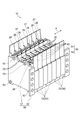
- FIG. 1 is a perspective view showing a configuration of a battery module.
- FIG. 2 is a diagram for explaining the relationship between the battery cell, the heat transfer plate, and the housing.
- a battery cell etc. are typically shown in the state seen from the electrode terminal 26 side of the battery cell. 2, illustration of the electrode terminals 26 and 26, the connection member 27, the cell holder 40, and the bracket 50 of the battery cell 20 shown in FIG. 1 is omitted.
- the battery module 10 holds a plurality of battery cells 20 arranged in one direction (array direction A), a plurality of heat transfer plates 30 attached to each of the plurality of battery cells 20, and each of the plurality of battery cells 20.
- the battery module 10 includes seven battery cells 20, seven heat transfer plates 30, and seven cell holders 40, but the number of battery cells 20, heat transfer plates 30, and cell holders 40 is as follows. It is not limited to this.
- the battery cell 20 is a storage battery such as a non-aqueous electrolyte secondary battery such as a lithium ion secondary battery, or an electric double layer capacitor.
- the battery cell 20 is configured by housing an electrode assembly in which a negative electrode, a separator, and a positive electrode are stacked in a case.
- the negative electrode and the positive electrode of the electrode assembly are fixed in an insulated state to the case, and are electrically connected to a pair of electrode terminals 26 and 26 protruding from the case, respectively.
- One electrode terminal 26 of the pair of electrode terminals 26 and 26 functions as a negative electrode terminal, and the other electrode terminal 26 functions as a positive electrode terminal.
- the electrode terminals 26 and 26 of the adjacent battery cells 20 are connected by a conductive connecting member 27 such as a bus bar. Thereby, the some battery cell 20 is electrically connected in series.
- the battery cell 20 has a main surface 21 and a side surface 22.
- the main surface 21 is a side surface (first side surface) of the battery cell 20 that intersects the arrangement direction A.
- the side surface 22 is a side surface (second side surface) of the battery cell 20 that intersects the main surface 21.
- the angle formed between the main surface 21 and the side surface 22 of the battery cell 20 is substantially 90 degrees.
- the heat transfer plate 30 is an element for radiating heat from the battery cells 20.
- the heat transfer plate 30 is attached to the corresponding battery cell 20.
- An example of the material of the heat transfer plate 30 is aluminum.
- the heat transfer plate 30 includes a first main body portion 31 and a second main body portion 32.
- the first main body 31 is a substantially rectangular flat plate that contacts the main surface 21 of the battery cell 20.
- the first main body 31 and the main surface 21 of the battery cell 20 are substantially parallel.
- the second main body portion 32 is a substantially rectangular flat plate extending from one end of the first main body portion 31 in a direction intersecting the main surface 21 so as to cover the side surface 22 of the battery cell 20.
- the 2nd main-body part 32 has the inner surface 32a and the outer surface 32b.
- the inner surface 32 a faces the side surface 22 of the battery cell 20 and is inclined with respect to the side surface 22.
- the outer surface 32b is a surface opposite to the side surface 22 of the battery cell 20, and is inclined with respect to the side surface 22 of the battery cell 20 similarly to the inner surface 32a.
- the outer surface 32 b is a facing surface that faces the inner wall surface 100 a provided with the heat conducting member 62 in the housing 100.
- the outer surface 32 b is thermally connected to the housing 100 through the heat conducting member 62. For this reason, the battery cell 20 is radiated to the housing 100 through the first main body portion 31, the second main body portion 32, and the heat conducting member 62 of the heat transfer plate 30. Details of the heat conducting member 62 will be described later.
- the second main body 32 has an inclined surface that is inclined with respect to the side surface 22 of the battery cell 20.
- the outer surface 32 b of the second main body portion 32 functions as an inclined surface because it is inclined with respect to the side surface 22 of the battery cell 20.
- the intersection angle ⁇ formed by the first main body portion 31 and the second main body portion 32 is larger than 90 degrees.
- the second body portion 32 is a surface orthogonal to the first body portion 31 and an angle obtained by subtracting 90 degrees from the intersection angle ⁇ with respect to a virtual surface parallel to the side surface 22 of the battery cell 20. It is inclined by (angle ⁇ shown in FIG. 3B described later). A method of determining the angle ⁇ will be described later with reference to FIG.
- the cell holder 40 holds the corresponding battery cell 20.
- the cell holder 40 holds the battery cell 20 so that the main surface 21 of the battery cell 20 is exposed in order to bring the first main body portion 31 of the heat transfer plate 30 into contact with the main surface 21 of the battery cell 20.
- An example of the material of the cell holder 40 is resin.
- the cell holder 40 may hold the battery cell 20 so that the surface of the battery cell 20 opposite to the main surface 21 is also exposed.
- the cell holder 40 is configured to have side plates that face the respective side surfaces (including the side surface 22) of the battery cell 20 excluding the main surface 21 of the battery cell 20 and the opposite surface thereof. In that case, each side plate of the cell holder 40 abuts on each side surface of the corresponding battery cell 20, whereby the battery cell 20 can be held.
- the pair of brackets 50, 50 sandwich the plurality of battery cells 20 from both sides in the arrangement direction A, thereby applying a restraining load to the plurality of battery cells 20 and fixing the battery module 10 to the housing 100.
- the pair of brackets 50 and 50 are made of a material having high rigidity, for example, a metal such as iron.
- One bracket 50 is arranged on one side in the arrangement direction A in the plurality of arranged battery cells 20.
- the other bracket 50 is arranged on the other side in the arrangement direction A in the plurality of arranged battery cells 20.
- Each of the pair of brackets 50, 50 has a clamping part 51 and an attachment part 52.
- the clamping part 51 is a substantially rectangular flat plate.
- the clamping part 51 of one bracket 50 and the clamping part 51 of the other bracket 50 are connected by a connecting member 53 such as a bolt, for example.
- the clamping parts 51 are connected to each other by a connecting member 53 so that a force is applied so as to approach each other in the arrangement direction A. Thereby, the clamping parts 51 apply a binding load in the arrangement direction A to the plurality of battery cells 20.
- the attachment portion 52 is a substantially rectangular flat plate extending from the end of the sandwiching portion 51 on the housing 100 side to the opposite side of the battery cell 20.
- the attachment portion 52 is provided with a hole through which a bolt used when attaching the battery module 10 to the housing 100 is inserted.
- the surface of the attachment portion 52 that contacts the housing is located closer to the housing 100 than the second main body portion 32 of the heat transfer plate 30.
- the offset between the surface and the second main body 32 in the direction orthogonal to the inner wall surface 100a of the housing 100 is, for example, about several millimeters.
- the elastic member (not shown) is a plate-like member provided between one bracket 50 and the battery cell 20.
- the elastic member is made of an elastically deformable material such as rubber and a resin sponge.
- the elastic member absorbs the expansion of the battery cell 20 in the battery module 10.
- the surface of the attachment portion 52 that contacts the housing 100 is located closer to the housing 100 than the elastic member.
- the offset between the surface and the elastic member in the direction orthogonal to the inner wall surface 100a of the housing 100 is, for example, 3 mm or more and 12 mm or less.
- the battery module 10 configured in this manner is attached to the housing 100 to form a battery pack.
- the second main body portion 32 of the heat transfer plate 30 is thermally connected to the housing 100 via the heat conducting member 62.
- the heat conducting member 62 is a solid layer formed by curing a liquid heat conducting material (TIM: Thermal Interface Material) 60.
- the heat conductive material 60 is, for example, a material having a high heat conductivity, and has a heat conductivity of, for example, 1.5 W / m ⁇ K or more.
- the thermal conductivity of the heat conductive material may be 2 W / m ⁇ K or more, 2.5 W / m ⁇ K, or 3.0 W / m ⁇ K or more.
- Examples of the heat conductive material 60 include polyurethane resin.
- the heat conducting member 62 may have viscosity.
- the solid layer may be a layer having a certain volume and shape, and may be a gel layer.
- the heat conducting member 62 may have adhesiveness.
- an end portion (one end portion) of the second main body portion 32 on the first main body portion 31 side is referred to as an end portion 321 and illustrated.
- an end portion (the other end portion) opposite to the end portion 321 in the second main body portion 32 is referred to as an end portion 322 and illustrated.
- the length of the heat transfer plate 30 in the extending direction of the second main body portion 32 that is, from the connection end to the front end of the second main body portion 32 with the first main body portion 31.
- the distance is defined as the length W.
- an angle formed between the extending direction of the second main body portion 32 and the side surface 22 of the battery cell 20 is defined as an angle ⁇ .
- the second main body of the heat transfer plate 30 is formed as shown in FIG.
- the part 32 is thermally connected to the housing 100 in a state where the heat conducting member 62 is pressed to the housing 100 side by the outer surface 32b. At this time, the heat conducting member 62 is pressed toward the housing 100 by the second main body portion 32 of the heat transfer plate 30 and is compressed between the second main body portion 32 and the housing 100. .
- the heat conductive member 62 heat conductive material 60 before being compressed in the direction perpendicular to the inner wall surface 100a is the thickness T1
- the heat conductive member 62 in the compressed portion Is smaller than the thickness T1.
- the heat conducting member 62 is compressed by the compression thickness t ⁇ b> 1 by the end portion 321 of the second main body portion 32, and by the end portion 322 of the second main body portion 32. It is compressed by the compression thickness t2.
- the compression thickness is the amount of change in the thickness of the heat conducting member 62 based on the thickness T1.
- the thickness of the heat conducting member 62 at the position corresponding to the end 321 is a thickness T1-t1 that is smaller than the thickness T1 by the compression thickness t1.
- the thickness of the heat conducting member 62 at the position corresponding to the end 322 is a thickness T1-t2 that is smaller than the thickness T1 by the compression thickness t2.
- the thickness of the heat conducting member 62 increases from the position corresponding to the end 322 of the second main body portion 32 toward the position corresponding to the end 321, and thus the heat conducting member 62. As a whole, the thickness falls within the range of the thickness T1-t2 to the thickness T1-t1.
- the compression rate of the heat conduction member 62 when the thickness of the heat conduction member 62 is T1-t1 is defined as a first compression rate. Further, the compression rate of the heat conduction member 62 when the thickness of the heat conduction member 62 is T1-t2 is set as the second compression rate.
- the compression rate of the heat conduction member 62 compressed at the compression thickness t1 is a compression rate at which the heat transfer rate between the second main body portion 32 and the heat transfer member 62 becomes a predetermined heat transfer rate. It is.
- the predetermined heat transfer coefficient is a heat transfer coefficient that can ensure heat dissipation of the battery cell 20. Normally, the heat transfer rate decreases as the compression rate decreases, so the compression thickness t1 is the minimum of the heat transfer member 62 necessary for causing the heat transfer member 62 to exhibit a heat transfer rate equal to or greater than the predetermined heat transfer rate. It can be said that the compression thickness is.
- the compression rate of the heat conduction member 62 compressed at the compression thickness t2 is a compression rate at which the reaction force of the heat conduction member 62 generated by the compression becomes a predetermined reaction force.
- the predetermined reaction force is a reaction force that does not hinder the maintenance of the state in which the battery module 10 is fixed to the housing 100. Normally, the reaction force increases as the compression ratio increases. Therefore, the compression thickness t2 is such that the heat conduction member 62 prevents the reaction force larger than the predetermined reaction force from being generated. It can be said that it is the maximum compression thickness.
- the first compression rate and the second compression rate described above may be determined based on, for example, the characteristics of the heat conducting member 62 (heat conducting material 60), or may be determined based on experimental data or the like. Also good.
- the outer surface 32b of the second main body portion 32 of the heat transfer plate 30 is thermally conductive so that the heat conducting member 62 is compressed at a compression rate that is equal to or higher than the first compression rate and equal to or lower than the second compression rate.
- the member 62 is pressed toward the housing 100 side.
- the compression rate of the heat conducting member 62 is adjusted by changing the compression thickness of the heat conducting member 62. Further, the compression thickness of the heat conducting member 62 is adjusted by, for example, changing the magnitude of pressing of the heat conducting member 62 by the second main body portion 32. In this case, if the compression thickness of the heat conducting member 62 at the position corresponding to the end 321 of the second main body 32 is determined, the compression thickness of the heat conducting member 62 at the position corresponding to the end 322 of the second main body 32. The height is determined according to the degree of inclination of the outer surface 32b, that is, the angle ⁇ .
- the heat conduction member 62 at a position corresponding to the end 321 of the second main body 32 is compressed at a compression rate equal to or higher than the first compression rate (that is, the compression thickness of the heat conduction member 62 is the compression thickness).
- the heat conducting member 62 is pressed to the housing 100 side by the outer surface 32b of the second main body 32. Such pressing is performed, for example, by adjusting the viscosity of the heat conductive material 60 or by adjusting the distance between the second main body portion 32 and the housing 100 when the battery module 10 is attached to the housing 100. Realized.
- the distance between the second body portion 32 and the housing 100 is, for example, orthogonal to the inner wall surface 100a of the housing 100 between the surface of the mounting portion 52 that contacts the housing 100 and the second body portion 32. Adjusted by changing the offset in direction.
- the heat conducting member 62 at the position corresponding to the end 322 of the second main body 32 is compressed with a compression thickness that is larger than the compression thickness of the heat conducting member 62 at the position corresponding to the end 321 by Wsin ⁇ . . Therefore, the compression thickness of the heat conducting member 62 at the position corresponding to the end portion 322 of the second main body portion 32 can depend on the angle ⁇ .
- the angle ⁇ is appropriately set, so that the second At a position corresponding to the end 322 of the main body portion 32, the heat conducting member 62 is compressed at a compression ratio that is greater than the first compression ratio and less than or equal to the second compression ratio (that is, the compression thickness of the heat conduction member 62. Is larger than the compression thickness t1 and equal to or less than the compression thickness t2), the heat conducting member 62 is pressed toward the housing 100 side.
- Such an angle ⁇ satisfies the condition of 0 ⁇ Wsin ⁇ ⁇ t2-t1.
- the compression thickness of the heat conducting member 62 becomes larger than the compression thickness t1 and becomes equal to or less than the compression thickness t2.
- the heat conduction member 62 is compressed at a compression rate equal to or higher than the first compression rate, that is, a compression rate at which the heat transfer rate between the second body portion 32 and the heat transfer member 62 is equal to or higher than a predetermined heat transfer rate.
- the compression is performed at a compression rate equal to or lower than the second compression rate, that is, a compression rate at which the reaction force of the heat conducting member 62 is equal to or less than a predetermined reaction force.
- the battery module 10 is mounted in a state where the heat transfer coefficient between the second main body portion 32 and the heat conductive member 62 is not less than a predetermined heat transfer coefficient and the reaction force of the heat conductive member 62 is not more than the predetermined reaction force. It can be attached to the body 100.
- the battery pack in which the heat dissipation of the battery cell 20 is improved can be obtained by attaching the battery module 10 to the housing 100 to form the battery pack.
- the compression rate of the heat conducting member 62 may be a compression rate that is equal to or higher than the first compression rate and lower than or equal to the second compression rate at least at a position corresponding to the end 322 of the second main body portion 32. Even in this case, since the thickness of the heat conducting member 62 increases from the position corresponding to the end 322 of the second main body 32 toward the position corresponding to the end 321, the second main body 32 is In this part, the image is compressed at a compression rate equal to or lower than the second compression rate. Therefore, the reaction force of the heat conducting member 62 is equal to or less than a predetermined reaction force.
- the heat conducting member 62 is compressed at a compression rate equal to or higher than the first compression rate at a position corresponding to at least the end 322 of the second main body portion 32. Therefore, at least at the end portion 322, the heat transfer coefficient between the second main body 32 and the heat conducting member 62 is equal to or higher than a predetermined heat transfer coefficient. Therefore, a battery pack with improved heat dissipation of the battery cell 20 can be obtained.
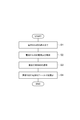
- step S1 the battery cell 20 and the like are assembled (step S1).
- step S1 the battery cell 20 is assembled into the cell holder 40 (see FIG. 1). Thereby, the battery cell 20 is held by the cell holder 40.
- step S1 as shown in FIG. 2, the first main body portion 31 of the heat transfer plate 30 contacts the main surface 21 of the battery cell 20, and the second main body portion 32 of the heat transfer plate 30 is connected to the battery cell 20.
- the heat transfer plate 30 is disposed so as to face the side surface 22.
- step S2 the plurality of battery cells 20 are arranged and restrained (step S2).
- step S2 the plurality of battery cells 20 incorporated in the cell holder 40 in step S1 are arranged along a direction (one direction) intersecting the main surface 21 (see FIG. 1).
- the first main body portion 31 of the heat transfer plate 30 is sandwiched between the adjacent battery cells 20.
- step S2 the plurality of battery cells 20 are sandwiched between the pair of brackets 50 and 50 from both sides in one direction.
- an elastic member is arrange
- a pair of brackets 50 and 50 are connected using the connection member 53, and the restraint load along one direction is added with respect to the some battery cell 20 arranged.
- step S3 the heat conductive material 60 is applied to the housing 100 (step S3).
- step S ⁇ b> 3 as shown in FIG. 5, a liquid heat conductive material 60 is applied on the inner wall surface 100 a of the housing 100.
- the inner wall surface 100a may be a horizontal plane. Thereby, it becomes easy to be maintained at the position where the heat conductive material 60 provided on the inner wall surface 100a is applied. As a result, for example, in step S4 described later, the work of attaching the battery module 10 to the housing 100 can be easily performed.
- step S4 the battery module 10 is fixed to the housing 100 (step S4).
- step S4 the side surface 22 of the battery cell 20 is substantially parallel to the inner wall surface 100a of the housing 100 by fixing the mounting portion 52 of the pair of brackets 50, 50 to the housing 100 with a bolt (not shown).
- the battery module 10 is attached to the housing 100.
- the 2nd main-body part 32 of the heat-transfer plate 30 contacts the heat conductive material 60 so that the inner wall surface 100a may be opposed.
- the heat conductive material 60 is compressed by the second main body portion 32 of the heat transfer plate 30 and the housing 100, and the thickness thereof is smaller than the thickness T1 shown in FIG.
- the heat conductive material 60 is cured in a state where the second main body portion 32 of the heat transfer plate 30 and the heat conductive material 60 are in contact with each other, and between the second main body portion 32 and the housing 100 (the inner wall surface 100a thereof).
- a heat conducting member 62 is formed.
- the battery module 10 is attached to the housing 100 so that the second main body portion 32 of the heat transfer plate 30 is thermally connected to the housing 100 via the heat conducting member 62, and the battery pack is manufactured. To do.
- FIG. 6 is a diagram for explaining details of a contact portion between the second main body portion of the heat transfer plate and the heat conductive material when the battery module 10 is attached to the housing 100.
- the second main body portion 32 of the heat transfer plate 30 comes into surface contact with the heat conductive material 60.
- bubbles V may be generated between the second main body portion 32 of the heat transfer plate 30 and the heat conductive material 60.
- the heat conduction material 60 is cured and the heat conduction member 62 is formed in the state where the bubbles V are present, a gap due to the bubbles V is generated between the heat transfer plate 30 and the heat conduction member 62. Therefore, improvement in heat transfer between the second main body portion 32 of the heat transfer plate 30 and the housing 100 is hindered. As a result, improvement in heat dissipation of the battery cell 20 is also hindered.
- the second main body portion 32 of the heat transfer plate 30 of the battery module 10 has an inclined surface that is inclined with respect to the side surface 22 of the battery cell 20.
- the outer surface 32 b of the second main body portion 32 is an inclined surface. If the inner wall surface 100a is a horizontal plane, the outer surface 32b of the second main body portion 32 is a plane inclined with respect to the horizontal plane.
- the outer surface 32 b is inclined with respect to the inner wall surface 100 a (horizontal plane) of the housing 100, so that the bubbles V are generated by the buoyancy as shown by the arrow in FIG. It moves upward along the outer surface 32b from between the portion 32 and the heat conductive material 60.
- the moved bubble V is discharged into a space between the second main body 32 and the battery cell 20, for example. In this manner, by using the inclination of the outer surface 32b, the possibility that the bubbles V move and are removed from between the second main body portion 32 and the heat conductive material 60 increases.
- the battery module 10 is attached to the housing 100 in a state where the second main body portion 32 of the heat transfer plate 30 and the heat conducting member 62 are in contact with each other without a gap. be able to.
- the heat of the second main body portion 32 of the heat transfer plate 30 can be transferred to the housing 100 via the heat conductive member 62 having high heat conductivity. Therefore, the heat dissipation of the battery cell 20 can be improved.
- the outer surface 32 b presses the heat conducting member 62 toward the housing 100 so that the heat conducting member 62 is compressed at the end portion 321 at the first compression rate.
- the heat conducting member 62 may be inclined so as to press the housing 100 toward the casing 100 so that the heat conducting member 62 is compressed at the second compression rate at the end 322.
- the heat transfer coefficient between the second main body portion 32 and the heat conduction member 62 is set.
- the battery module 10 can be attached to the housing 100 in a state where the heat transfer rate is equal to or higher than the predetermined heat transfer rate and the reaction force of the heat conducting member 62 is equal to or lower than the predetermined reaction force. Thereby, the battery pack in which the heat dissipation of the battery cell 20 is improved can be obtained.
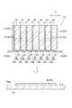
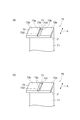
- the heat transfer plate 70 shown in FIG. 7A includes a first main body 71 and a second main body 72. Similarly to the heat transfer plate 30, the heat transfer plate 70 is also attached to the battery cell 20.
- the configuration and function of the first main body 71 are the same as those of the first main body 31 of the heat transfer plate 30.
- the intersection angle ⁇ formed by the first body portion 71 and the second body portion 72 may be the same as or different from the above-described intersection angle ⁇ .
- the intersection angle ⁇ may be 90 degrees, for example.
- the second main body 72 has an outer surface 72b.
- the outer surface 72b is a facing surface that faces the inner wall surface 100a of the housing 100 in a state where the battery module 10 is attached to the housing 100, similarly to the outer surface 32b.
- a groove 73 is provided on the outer surface 72b.
- the groove 73 extends from the edge of the second main body portion 72. In the example shown in FIG. 7A, the grooves 73 extend along the arrangement direction A. One end 731 and the other end 732 of the groove 73 are located at opposite edges of the second main body 72.
- the cross-sectional shape that intersects the extending direction of the groove 73 is a substantially rectangular shape.
- the groove 73 is defined by the bottom surface 73a and the side surface 73b.
- the distance from the outer surface 72 b to the bottom surface 73 a of the groove 73 in the direction orthogonal to the outer surface 72 b of the second main body 72, that is, the depth of the groove 73 increases as it approaches the one end 731 from the other end 732 of the groove 73. .
- the bottom surface 73a of the groove 73 is inclined with respect to the outer surface 72b.
- the bottom surface 73 a is an inclined surface that is inclined with respect to the side surface 22 of the battery cell 20. Even when the crossing angle ⁇ is larger than 90 degrees, if the bottom surface 73a of the groove 73 is inclined with respect to the side surface 22 of the battery cell 20, the bottom surface 73a of the groove 73 functions as an inclined surface.
- bubbles V generated in the vicinity of the groove 73 between the second main body 72 and the heat conductive material 60 when the battery module 10 is attached to the housing 100. Is taken into the groove 73 and moves along the bottom surface 73 a of the groove 73. More specifically, the bubble V can move to the edge of the second main body 72 along the direction in which the depth of the groove 73 becomes deeper, that is, the direction from the other end 732 toward the one end 731.
- the possibility that the bubbles V are removed from between the second main body portion 72 and the heat conductive material 60 can be increased.
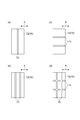
- the cross-sectional shape that intersects the extending direction of the groove 73 is not limited to a substantially rectangular shape.
- the cross-sectional shape that intersects the extending direction of the groove 73 may be a triangular shape.
- the inner surface 73 c that defines the groove 73 functions as an inclined surface that is inclined with respect to the side surface 22 of the battery cell 20, so that the bubbles V are removed from between the second main body portion 72 and the heat conductive material 60. The possibility increases.
- the cross-sectional shape of the groove 73 is triangular, when the battery module 10 is attached to the housing 100, the inner surface 73c that defines the groove 73 is inclined with respect to the surface of the heat conductive material 60 (that is, Since the surface defining the groove 73 is in contact with the heat conductive material 60 (with no part parallel to the surface of the heat conductive material 60), the possibility of bubbles V remaining in a part of the groove 73 is reduced. You can also.
- the groove 73 is formed in the second main body 72 by, for example, processing a flat plate member that constitutes the second main body 72.
- the second body portion 72 of the heat transfer plate 70 has been described with the groove provided so as to extend along the arrangement direction A, but the present invention is not limited to this, and the second heat transfer plate
- the two main body portions may be provided with grooves in various manners.
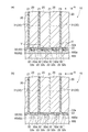
- the groove 73 may be provided in the second main body portion 72 so as to extend along a direction intersecting (for example, orthogonal to) the arrangement direction A. .
- the groove 73 may include a plurality of grooves.
- the plurality of grooves are a first groove and a second groove extending in the same direction.
- Each groove may be provided side by side so as to extend along a direction intersecting (for example, orthogonal to) the arrangement direction A as shown in FIG. 8B, or in FIG. It may be provided side by side so as to extend along the arrangement direction A as shown in FIG.
- the number of grooves is not particularly limited.
- first groove and the second groove may intersect each other. As shown in FIG. 8D, even if the two grooves 73 extending along the arrangement direction A and the two grooves 73 extending along the direction intersecting the arrangement direction A intersect each other. Good.
- two grooves extending along the arrangement direction A are first grooves
- two grooves extending along a direction intersecting with the arrangement direction A are second grooves.
- the cross-sectional shape that intersects the extending direction of the groove 73 is a substantially rectangular shape or a triangular shape has been described.
- a trapezoidal shape or the like may be used.
- the example in which both the one end 731 and the other end 732 of the groove 73 are located at the edge of the second main body portion 72 has been described, but at least the depth of the groove 73 becomes deeper.
- the one end of the side should just be located in the edge of the 2nd main-body part 72.
- the outer surface 32b of the 2nd main-body part 32 demonstrated the example which inclines so that it may approach the side surface 22 of the battery cell 20 as it goes to the end part 321 from the end part 322 in the said embodiment
- the inclination of the outer surface 32b is demonstrated.
- the aspect is not limited to this.
- the outer surface 32b may be inclined so as to approach the side surface 22 of the battery cell 20 from the end 321 toward the end 322.
- the outer surface 32b is inclined so as to approach the side surface 22 of the battery cell 20 from one end to the other end of the pair of ends that are different from the end 321 and the end 322. May be.
- SYMBOLS 10 Battery module, 20 ... Battery cell, 21 ... Main surface (1st side surface), 22 ... Side surface (2nd side surface), 30, 70 ... Heat-transfer plate, 31, 71 ... 1st main-body part, 32, 72 ... 2nd main-body part, 32b, 72b ... outer surface (facing surface, inclined surface), 60 ... heat conducting material, 62 ... heat conducting member, 73 ... groove, 73a ... bottom surface (tilted surface), 73c ... inner surface (tilted surface), 100: casing, 100a: inner wall surface.
Landscapes
- Engineering & Computer Science (AREA)
- Chemical & Material Sciences (AREA)
- Chemical Kinetics & Catalysis (AREA)
- Electrochemistry (AREA)
- General Chemical & Material Sciences (AREA)
- Manufacturing & Machinery (AREA)
- Power Engineering (AREA)
- Microelectronics & Electronic Packaging (AREA)
- Physics & Mathematics (AREA)
- Algebra (AREA)
- General Physics & Mathematics (AREA)
- Mathematical Analysis (AREA)
- Mathematical Optimization (AREA)
- Pure & Applied Mathematics (AREA)
- Secondary Cells (AREA)
- Battery Mounting, Suspending (AREA)
- Electric Double-Layer Capacitors Or The Like (AREA)
Applications Claiming Priority (2)
| Application Number | Priority Date | Filing Date | Title |
|---|---|---|---|
| JP2015203404A JP2017076526A (ja) | 2015-10-15 | 2015-10-15 | 電池モジュール |
| JP2015-203404 | 2015-10-15 |
Publications (1)
| Publication Number | Publication Date |
|---|---|
| WO2017064978A1 true WO2017064978A1 (ja) | 2017-04-20 |
Family
ID=58517184
Family Applications (1)
| Application Number | Title | Priority Date | Filing Date |
|---|---|---|---|
| PCT/JP2016/077503 Ceased WO2017064978A1 (ja) | 2015-10-15 | 2016-09-16 | 電池モジュール |
Country Status (2)
| Country | Link |
|---|---|
| JP (1) | JP2017076526A (enExample) |
| WO (1) | WO2017064978A1 (enExample) |
Cited By (5)
| Publication number | Priority date | Publication date | Assignee | Title |
|---|---|---|---|---|
| US20170200995A1 (en) * | 2016-01-07 | 2017-07-13 | GM Global Technology Operations LLC | Cure in place thermal interface material |
| CN109802063A (zh) * | 2017-11-17 | 2019-05-24 | 丰田自动车株式会社 | 电池组、电池组制造方法和介入构件 |
| CN111969137A (zh) * | 2019-05-20 | 2020-11-20 | 奥迪股份公司 | 用于将导热介质引入到电池模块和冷却底板之间的方法、注射系统和电池模块 |
| WO2020254069A1 (de) * | 2019-06-18 | 2020-12-24 | Audi Ag | Verfahren zum einbringen einer wärmeleitfähigen füllmasse mit variablem anteil an füllstoff, batteriemodulvorrichtung und anlage zum einbringen von füllmasse |
| US20210143379A1 (en) * | 2019-11-13 | 2021-05-13 | Tdk Corporation | Stacked battery pack |
Families Citing this family (3)
| Publication number | Priority date | Publication date | Assignee | Title |
|---|---|---|---|---|
| JP6965717B2 (ja) * | 2017-12-13 | 2021-11-10 | トヨタ自動車株式会社 | 電池パックの製造方法 |
| JP7135348B2 (ja) * | 2018-03-09 | 2022-09-13 | 株式会社デンソー | 電池装置 |
| KR20250110536A (ko) * | 2024-01-12 | 2025-07-21 | 주식회사 엘지에너지솔루션 | 배터리 팩 |
Citations (3)
| Publication number | Priority date | Publication date | Assignee | Title |
|---|---|---|---|---|
| JP2013071870A (ja) * | 2011-09-28 | 2013-04-22 | Kyocera Corp | 結晶育成装置および結晶の育成方法 |
| JP2014192120A (ja) * | 2013-03-28 | 2014-10-06 | Toyota Industries Corp | 電池パック |
| JP2015050366A (ja) * | 2013-09-03 | 2015-03-16 | ウシオ電機株式会社 | 半導体レーザ装置 |
Family Cites Families (4)
| Publication number | Priority date | Publication date | Assignee | Title |
|---|---|---|---|---|
| KR101361375B1 (ko) * | 2009-12-07 | 2014-02-11 | 스미도모쥬기가이고교 가부시키가이샤 | 쇼벨 |
| JP2012004398A (ja) * | 2010-06-18 | 2012-01-05 | Sumitomo Heavy Ind Ltd | 蓄電モジュール |
| JP5451694B2 (ja) * | 2011-07-05 | 2014-03-26 | 株式会社日立製作所 | 非水電解質電池モジュール |
| JP5904113B2 (ja) * | 2012-12-10 | 2016-04-13 | 株式会社豊田自動織機 | 電池モジュール及び電池モジュールの製造方法 |
-
2015
- 2015-10-15 JP JP2015203404A patent/JP2017076526A/ja active Pending
-
2016
- 2016-09-16 WO PCT/JP2016/077503 patent/WO2017064978A1/ja not_active Ceased
Patent Citations (3)
| Publication number | Priority date | Publication date | Assignee | Title |
|---|---|---|---|---|
| JP2013071870A (ja) * | 2011-09-28 | 2013-04-22 | Kyocera Corp | 結晶育成装置および結晶の育成方法 |
| JP2014192120A (ja) * | 2013-03-28 | 2014-10-06 | Toyota Industries Corp | 電池パック |
| JP2015050366A (ja) * | 2013-09-03 | 2015-03-16 | ウシオ電機株式会社 | 半導体レーザ装置 |
Cited By (14)
| Publication number | Priority date | Publication date | Assignee | Title |
|---|---|---|---|---|
| US10116018B2 (en) * | 2016-01-07 | 2018-10-30 | GM Global Technology Operations LLC | Cure in place thermal interface material |
| US20170200995A1 (en) * | 2016-01-07 | 2017-07-13 | GM Global Technology Operations LLC | Cure in place thermal interface material |
| US11075418B2 (en) | 2017-11-17 | 2021-07-27 | Toyota Jidosha Kabushiki Kaisha | Battery pack, manufacturing method of battery pack, and intervening member |
| CN109802063A (zh) * | 2017-11-17 | 2019-05-24 | 丰田自动车株式会社 | 电池组、电池组制造方法和介入构件 |
| CN109802063B (zh) * | 2017-11-17 | 2021-08-17 | 丰田自动车株式会社 | 电池组、电池组制造方法和介入构件 |
| CN111969137A (zh) * | 2019-05-20 | 2020-11-20 | 奥迪股份公司 | 用于将导热介质引入到电池模块和冷却底板之间的方法、注射系统和电池模块 |
| CN111969137B (zh) * | 2019-05-20 | 2022-09-23 | 奥迪股份公司 | 用于将导热介质引入到电池模块和冷却底板之间的方法、注射系统和电池模块 |
| WO2020254069A1 (de) * | 2019-06-18 | 2020-12-24 | Audi Ag | Verfahren zum einbringen einer wärmeleitfähigen füllmasse mit variablem anteil an füllstoff, batteriemodulvorrichtung und anlage zum einbringen von füllmasse |
| CN112803091A (zh) * | 2019-11-13 | 2021-05-14 | Tdk株式会社 | 层叠型电池组 |
| JP2021077595A (ja) * | 2019-11-13 | 2021-05-20 | Tdk株式会社 | 積層型バッテリーパック |
| US20210143379A1 (en) * | 2019-11-13 | 2021-05-13 | Tdk Corporation | Stacked battery pack |
| JP7310561B2 (ja) | 2019-11-13 | 2023-07-19 | Tdk株式会社 | 積層型バッテリーパック |
| CN112803091B (zh) * | 2019-11-13 | 2024-03-22 | Tdk株式会社 | 层叠型电池组 |
| US12142777B2 (en) * | 2019-11-13 | 2024-11-12 | Tdk Corporation | Stacked battery pack |
Also Published As
| Publication number | Publication date |
|---|---|
| JP2017076526A (ja) | 2017-04-20 |
Similar Documents
| Publication | Publication Date | Title |
|---|---|---|
| WO2017064978A1 (ja) | 電池モジュール | |
| US11380948B2 (en) | Battery module | |
| CN109994798B (zh) | 电池模块及其制造方法 | |
| EP2357689A1 (en) | Battery module | |
| CN106025120B (zh) | 蓄电组件 | |
| JP5906962B2 (ja) | 二次電池モジュールのセルホルダ | |
| JP6926630B2 (ja) | 電池モジュール | |
| US20190097284A1 (en) | Power storage device pack | |
| WO2019151037A1 (ja) | 電池モジュール及び電池パック | |
| JP6558198B2 (ja) | 電池モジュール | |
| JP5835315B2 (ja) | 蓄電モジュールユニット及び蓄電モジュールユニットの製造方法 | |
| CN105359331A (zh) | 电池组 | |
| CN110337738B (zh) | 电池模块以及电池模块的制造方法 | |
| JP6690452B2 (ja) | 電池モジュール | |
| JP6657748B2 (ja) | 電池モジュール及び電池モジュールの製造方法 | |
| JP2017103158A (ja) | 電池パック | |
| JP6681436B2 (ja) | 蓄電モジュール | |
| US11342608B2 (en) | Battery module | |
| WO2016031628A1 (ja) | 電池パック | |
| JP2019012652A (ja) | 電池モジュール及び電池パック | |
| JP6681435B2 (ja) | 蓄電モジュール | |
| CN219917323U (zh) | 单体组装体及包括其的电池模块 | |
| CN113544902A (zh) | 电池模块及包括该电池模块的电池组 | |
| US12482901B2 (en) | Battery module | |
| JP6932978B2 (ja) | 電池モジュール |
Legal Events
| Date | Code | Title | Description |
|---|---|---|---|
| 121 | Ep: the epo has been informed by wipo that ep was designated in this application |
Ref document number: 16855232 Country of ref document: EP Kind code of ref document: A1 |
|
| NENP | Non-entry into the national phase |
Ref country code: DE |
|
| 122 | Ep: pct application non-entry in european phase |
Ref document number: 16855232 Country of ref document: EP Kind code of ref document: A1 |