WO2017061600A1 - Dispositif microfluidique et procédé d'analyse d'échantillon - Google Patents
Dispositif microfluidique et procédé d'analyse d'échantillon Download PDFInfo
- Publication number
- WO2017061600A1 WO2017061600A1 PCT/JP2016/079956 JP2016079956W WO2017061600A1 WO 2017061600 A1 WO2017061600 A1 WO 2017061600A1 JP 2016079956 W JP2016079956 W JP 2016079956W WO 2017061600 A1 WO2017061600 A1 WO 2017061600A1
- Authority
- WO
- WIPO (PCT)
- Prior art keywords
- microwell
- substrate
- microfluidic device
- sample
- wall layer
- Prior art date
Links
Images


Classifications
-
- B—PERFORMING OPERATIONS; TRANSPORTING
- B01—PHYSICAL OR CHEMICAL PROCESSES OR APPARATUS IN GENERAL
- B01L—CHEMICAL OR PHYSICAL LABORATORY APPARATUS FOR GENERAL USE
- B01L3/00—Containers or dishes for laboratory use, e.g. laboratory glassware; Droppers
- B01L3/50—Containers for the purpose of retaining a material to be analysed, e.g. test tubes
- B01L3/502—Containers for the purpose of retaining a material to be analysed, e.g. test tubes with fluid transport, e.g. in multi-compartment structures
- B01L3/5027—Containers for the purpose of retaining a material to be analysed, e.g. test tubes with fluid transport, e.g. in multi-compartment structures by integrated microfluidic structures, i.e. dimensions of channels and chambers are such that surface tension forces are important, e.g. lab-on-a-chip
- B01L3/502715—Containers for the purpose of retaining a material to be analysed, e.g. test tubes with fluid transport, e.g. in multi-compartment structures by integrated microfluidic structures, i.e. dimensions of channels and chambers are such that surface tension forces are important, e.g. lab-on-a-chip characterised by interfacing components, e.g. fluidic, electrical, optical or mechanical interfaces
-
- B—PERFORMING OPERATIONS; TRANSPORTING
- B81—MICROSTRUCTURAL TECHNOLOGY
- B81B—MICROSTRUCTURAL DEVICES OR SYSTEMS, e.g. MICROMECHANICAL DEVICES
- B81B1/00—Devices without movable or flexible elements, e.g. microcapillary devices
- B81B1/006—Microdevices formed as a single homogeneous piece, i.e. wherein the mechanical function is obtained by the use of the device, e.g. cutters
-
- B—PERFORMING OPERATIONS; TRANSPORTING
- B81—MICROSTRUCTURAL TECHNOLOGY
- B81B—MICROSTRUCTURAL DEVICES OR SYSTEMS, e.g. MICROMECHANICAL DEVICES
- B81B3/00—Devices comprising flexible or deformable elements, e.g. comprising elastic tongues or membranes
- B81B3/0064—Constitution or structural means for improving or controlling the physical properties of a device
- B81B3/0083—Optical properties
-
- G—PHYSICS
- G01—MEASURING; TESTING
- G01N—INVESTIGATING OR ANALYSING MATERIALS BY DETERMINING THEIR CHEMICAL OR PHYSICAL PROPERTIES
- G01N21/00—Investigating or analysing materials by the use of optical means, i.e. using sub-millimetre waves, infrared, visible or ultraviolet light
- G01N21/01—Arrangements or apparatus for facilitating the optical investigation
- G01N21/03—Cuvette constructions
-
- G—PHYSICS
- G01—MEASURING; TESTING
- G01N—INVESTIGATING OR ANALYSING MATERIALS BY DETERMINING THEIR CHEMICAL OR PHYSICAL PROPERTIES
- G01N21/00—Investigating or analysing materials by the use of optical means, i.e. using sub-millimetre waves, infrared, visible or ultraviolet light
- G01N21/62—Systems in which the material investigated is excited whereby it emits light or causes a change in wavelength of the incident light
- G01N21/63—Systems in which the material investigated is excited whereby it emits light or causes a change in wavelength of the incident light optically excited
- G01N21/64—Fluorescence; Phosphorescence
- G01N21/6428—Measuring fluorescence of fluorescent products of reactions or of fluorochrome labelled reactive substances, e.g. measuring quenching effects, using measuring "optrodes"
-
- G—PHYSICS
- G01—MEASURING; TESTING
- G01N—INVESTIGATING OR ANALYSING MATERIALS BY DETERMINING THEIR CHEMICAL OR PHYSICAL PROPERTIES
- G01N21/00—Investigating or analysing materials by the use of optical means, i.e. using sub-millimetre waves, infrared, visible or ultraviolet light
- G01N21/62—Systems in which the material investigated is excited whereby it emits light or causes a change in wavelength of the incident light
- G01N21/63—Systems in which the material investigated is excited whereby it emits light or causes a change in wavelength of the incident light optically excited
- G01N21/64—Fluorescence; Phosphorescence
- G01N21/645—Specially adapted constructive features of fluorimeters
- G01N21/6452—Individual samples arranged in a regular 2D-array, e.g. multiwell plates
-
- G—PHYSICS
- G01—MEASURING; TESTING
- G01N—INVESTIGATING OR ANALYSING MATERIALS BY DETERMINING THEIR CHEMICAL OR PHYSICAL PROPERTIES
- G01N33/00—Investigating or analysing materials by specific methods not covered by groups G01N1/00 - G01N31/00
- G01N33/48—Biological material, e.g. blood, urine; Haemocytometers
- G01N33/50—Chemical analysis of biological material, e.g. blood, urine; Testing involving biospecific ligand binding methods; Immunological testing
- G01N33/52—Use of compounds or compositions for colorimetric, spectrophotometric or fluorometric investigation, e.g. use of reagent paper and including single- and multilayer analytical elements
-
- B—PERFORMING OPERATIONS; TRANSPORTING
- B01—PHYSICAL OR CHEMICAL PROCESSES OR APPARATUS IN GENERAL
- B01L—CHEMICAL OR PHYSICAL LABORATORY APPARATUS FOR GENERAL USE
- B01L2300/00—Additional constructional details
- B01L2300/04—Closures and closing means
- B01L2300/046—Function or devices integrated in the closure
-
- B—PERFORMING OPERATIONS; TRANSPORTING
- B01—PHYSICAL OR CHEMICAL PROCESSES OR APPARATUS IN GENERAL
- B01L—CHEMICAL OR PHYSICAL LABORATORY APPARATUS FOR GENERAL USE
- B01L2300/00—Additional constructional details
- B01L2300/08—Geometry, shape and general structure
- B01L2300/0809—Geometry, shape and general structure rectangular shaped
- B01L2300/0829—Multi-well plates; Microtitration plates
-
- B—PERFORMING OPERATIONS; TRANSPORTING
- B01—PHYSICAL OR CHEMICAL PROCESSES OR APPARATUS IN GENERAL
- B01L—CHEMICAL OR PHYSICAL LABORATORY APPARATUS FOR GENERAL USE
- B01L2300/00—Additional constructional details
- B01L2300/08—Geometry, shape and general structure
- B01L2300/0861—Configuration of multiple channels and/or chambers in a single devices
- B01L2300/0877—Flow chambers
-
- B—PERFORMING OPERATIONS; TRANSPORTING
- B01—PHYSICAL OR CHEMICAL PROCESSES OR APPARATUS IN GENERAL
- B01L—CHEMICAL OR PHYSICAL LABORATORY APPARATUS FOR GENERAL USE
- B01L2300/00—Additional constructional details
- B01L2300/08—Geometry, shape and general structure
- B01L2300/0887—Laminated structure
-
- B—PERFORMING OPERATIONS; TRANSPORTING
- B01—PHYSICAL OR CHEMICAL PROCESSES OR APPARATUS IN GENERAL
- B01L—CHEMICAL OR PHYSICAL LABORATORY APPARATUS FOR GENERAL USE
- B01L2300/00—Additional constructional details
- B01L2300/16—Surface properties and coatings
- B01L2300/161—Control and use of surface tension forces, e.g. hydrophobic, hydrophilic
-
- B—PERFORMING OPERATIONS; TRANSPORTING
- B01—PHYSICAL OR CHEMICAL PROCESSES OR APPARATUS IN GENERAL
- B01L—CHEMICAL OR PHYSICAL LABORATORY APPARATUS FOR GENERAL USE
- B01L7/00—Heating or cooling apparatus; Heat insulating devices
- B01L7/52—Heating or cooling apparatus; Heat insulating devices with provision for submitting samples to a predetermined sequence of different temperatures, e.g. for treating nucleic acid samples
-
- B—PERFORMING OPERATIONS; TRANSPORTING
- B81—MICROSTRUCTURAL TECHNOLOGY
- B81B—MICROSTRUCTURAL DEVICES OR SYSTEMS, e.g. MICROMECHANICAL DEVICES
- B81B2201/00—Specific applications of microelectromechanical systems
- B81B2201/05—Microfluidics
- B81B2201/057—Micropipets, dropformers
-
- B—PERFORMING OPERATIONS; TRANSPORTING
- B81—MICROSTRUCTURAL TECHNOLOGY
- B81B—MICROSTRUCTURAL DEVICES OR SYSTEMS, e.g. MICROMECHANICAL DEVICES
- B81B2201/00—Specific applications of microelectromechanical systems
- B81B2201/05—Microfluidics
- B81B2201/058—Microfluidics not provided for in B81B2201/051 - B81B2201/054
-
- B—PERFORMING OPERATIONS; TRANSPORTING
- B81—MICROSTRUCTURAL TECHNOLOGY
- B81B—MICROSTRUCTURAL DEVICES OR SYSTEMS, e.g. MICROMECHANICAL DEVICES
- B81B2203/00—Basic microelectromechanical structures
- B81B2203/03—Static structures
- B81B2203/0323—Grooves
- B81B2203/0338—Channels
-
- B—PERFORMING OPERATIONS; TRANSPORTING
- B81—MICROSTRUCTURAL TECHNOLOGY
- B81B—MICROSTRUCTURAL DEVICES OR SYSTEMS, e.g. MICROMECHANICAL DEVICES
- B81B2203/00—Basic microelectromechanical structures
- B81B2203/03—Static structures
- B81B2203/0353—Holes
-
- G—PHYSICS
- G01—MEASURING; TESTING
- G01N—INVESTIGATING OR ANALYSING MATERIALS BY DETERMINING THEIR CHEMICAL OR PHYSICAL PROPERTIES
- G01N21/00—Investigating or analysing materials by the use of optical means, i.e. using sub-millimetre waves, infrared, visible or ultraviolet light
- G01N21/62—Systems in which the material investigated is excited whereby it emits light or causes a change in wavelength of the incident light
- G01N21/63—Systems in which the material investigated is excited whereby it emits light or causes a change in wavelength of the incident light optically excited
- G01N21/64—Fluorescence; Phosphorescence
- G01N21/6428—Measuring fluorescence of fluorescent products of reactions or of fluorochrome labelled reactive substances, e.g. measuring quenching effects, using measuring "optrodes"
- G01N2021/6439—Measuring fluorescence of fluorescent products of reactions or of fluorochrome labelled reactive substances, e.g. measuring quenching effects, using measuring "optrodes" with indicators, stains, dyes, tags, labels, marks
Definitions
- the present invention relates to a microfluidic device having a microwell array and a sample analysis method using the microfluidic device.
- microwell arrays having various types of fine channel structures formed using etching techniques, photolithography techniques, or fine plastic molding methods used in semiconductor circuit manufacturing techniques have been studied. ing.
- the wells of these microwell arrays are used as chemical reaction vessels for causing various biochemical or chemical reactions in a small volume of fluid.
- Materials for manufacturing microfluidic devices having microwell arrays include hard materials such as silicone and glass, various polymer resins such as PDMS (polydimethylsiloxane), and soft materials such as silicone rubber. It has been.
- Patent Documents 1 to 3 disclose using such a microfluidic device as various microchips and biochips.
- digital PCR technology involves PCR amplification by dividing a mixture of a reagent and nucleic acid into countless microdroplets so that a signal such as fluorescence can be detected from the droplet containing nucleic acid. This is a technique for performing quantification by counting the number of detected droplets.
- a method for producing a microdroplet As a method for producing a microdroplet, a method for producing a microdroplet by dividing with a sealing liquid, or a reagent is put into a hole formed on a substrate, and then a microdroplet is made by adding a sealing liquid. A manufacturing method and the like are being studied.
- Patent Document 1 In a fluid system for acquiring a fluorescence value emitted from a biomolecule, a method for reducing autofluorescence by adding a pigment to a material constituting a fluid device used in the fluid system has been studied (for example, Patent Document 1). To 3). This is because if the auto-fluorescence derived from the material is detected as noise, it interferes with the detection of the fluorescence signal.
- the size of the microwell Since microwells are very small, if a pigment is added when forming a microwell array, the size of the microwells may be close to the size of the microwells depending on the particle size of the pigment, and the microwells may not be formed with high accuracy.
- the source of such autofluorescence is not limited to the material forming the microwell array. Therefore, it is difficult to completely solve the problem only by reducing the autofluorescence of the material.
- the microfluidic device includes a substrate capable of transmitting electromagnetic waves and having no autofluorescence, and a wall portion formed on the substrate and having a plurality of through holes formed in the thickness direction.
- a microwell array having a layer, and a lid member disposed to face the substrate in a state of being separated from the wall layer, and the microwell is formed by the substrate and the through hole formed in the wall layer.
- the wall layer is formed of a material containing a colored component that absorbs an electromagnetic wave having a predetermined wavelength.
- the colored component may be a pigment, and the particle diameter of the pigment may be 1/5 or less of the minimum dimension of the microwell.
- a sample analysis method is a sample analysis method using the microfluidic device according to the first aspect, wherein a sample is supplied into the microwell (sample supply step), and a sealing liquid The sample is encapsulated in the microwell using (encapsulation step), and after encapsulating the sample in the microwell, the microfluidic device is irradiated with electromagnetic waves (electromagnetic wave irradiation step), and the electromagnetic waves are irradiated The microwell is observed from the substrate side (sample observation step).
- microwell array According to the microwell array according to the first aspect of the present invention, it is possible to provide a microwell array in which microwells are formed with high accuracy while suppressing autofluorescence of the material. Moreover, according to the sample analysis method according to the second aspect of the present invention, it is possible to analyze the sample accommodated in the microwell while suitably eliminating minute fluorescence noise.
- FIG. 2 is a cross-sectional view taken along line bb of FIG. It is a figure which shows the state at the time of use of the microfluidic device which concerns on one Embodiment of this invention. It is a figure which shows the state at the time of use of the microfluidic device which concerns on one Embodiment of this invention. It is a figure for demonstrating the effect of the sample analysis method using the microfluidic device which concerns on one Embodiment of this invention. It is a table
- FIG. 2 is a microscopic image of Example 1.
- Example 2 is a microscopic image of Comparative Example 1.
- 4 is a table showing the difference in fluorescence intensity depending on the presence or absence of a pigment in the material used in Example 1. It is a perspective view which shows the modification of the microfluidic device which concerns on one Embodiment of this invention. 4 is a result of bright field observation of Example 2. It is a result of the bright field observation of the comparative example 2.
- 2 is a microscopic image of Example 2. It is a microscope image of the comparative example 2.
- FIG. 1 is a perspective view showing a microfluidic device 1 according to this embodiment.
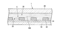
- FIG. 2 is a cross-sectional view taken along line bb in FIG.
- the microfluidic device 1 includes a substrate 10, a lid member 20, and a microwell array 30.
- the lid member 20 is disposed opposite to the substrate 10.
- the microwell array 30 is provided between the substrate 10 and the lid member 20.
- the substrate 10 can transmit electromagnetic waves.
- the electromagnetic wave include X-rays, ultraviolet rays, visible rays, and infrared rays. Since the substrate 10 can transmit electromagnetic waves, fluorescence, phosphorescence, and the like generated in the sample sealed in the microfluidic device 1 can be observed from the substrate 10 side.
- the substrate 10 may be able to transmit only electromagnetic waves in a predetermined wavelength range. For example, when detecting fluorescence having a peak in the wavelength range of 350 to 700 nm, which is the visible light region, of the sample in the microwell, a substrate that can transmit at least visible light in the wavelength range may be used.
- Examples of the material for forming the substrate 10 include glass and resin.
- Examples of the resin substrate include ABS resin, polycarbonate resin, COC (cycloolefin copolymer), COP (cycloolefin polymer), acrylic resin, polyvinyl chloride, polystyrene resin, polyethylene resin, polypropylene resin, polyvinyl acetate, and PET (polyethylene). Terephthalate), PEN (polyethylene naphthalate) and the like. These resins may contain various additives, and a plurality of resins may be mixed.
- substantially has no autofluorescence means that the substrate has no autofluorescence of the wavelength used for detection of the experimental results, or has influence on detection of the experimental results even if it has autofluorescence. It means that it is weak enough not to give. For example, if the autofluorescence is about 1/2 or less and 1/10 or less compared to the fluorescence of the detection target, it can be said that it is so weak that it does not affect the detection of the experimental result.
- the thickness of the substrate 10 can be determined as appropriate, but is preferably 5 millimeters (mm) or less, more preferably 2 mm or less, and even more preferably 1.6 mm or less.
- the lid member 20 is a member formed in a plate shape or a sheet shape, and has a first hole 21 and a second hole 22 penetrating in the thickness direction.
- the first hole 21 and the second hole 22 communicate with the internal space S including the microwell array 30 in the completed microfluidic device 1.
- the first hole 21 and the second hole 22 function as an inlet for supplying fluid to the internal space and an outlet for discharging the fluid, respectively.
- the material for forming the lid member 20 and the thickness of the lid member 20 can be the same as those of the substrate 10.
- the electromagnetic wave permeability of the lid member 20 can be set as appropriate. That is, when the electromagnetic wave irradiation process to be described later is not performed from the lid member 20 side, the lid member 20 may not be able to transmit electromagnetic waves.
- the microwell array 30 has a bottom layer 31, a wall layer 32, and a plurality of microwells 33.
- the bottom layer 31 is provided on the substrate 10.
- the wall layer 32 is formed on the bottom layer 31.
- the plurality of microwells 33 includes a bottom layer 31 and a plurality of through holes 32 a formed in the thickness direction of the wall layer 32.
- the plurality of microwells 33 are formed in an array in the wall layer 32.
- the bottom layer 31 constitutes the bottom surface of the microwell 33. Therefore, when it is desired to impart hydrophilicity to the bottom surface, the bottom layer 31 may be formed from a hydrophilic material. If it is desired to impart hydrophobicity to the bottom surface, the bottom layer 31 may be formed of a hydrophobic material.
- the bottom layer 31 is preferably formed so that the bottom layer 31 can transmit electromagnetic waves, so that it does not hinder the observation of the sample in the microwell 33 from the substrate 10 side.
- the bottom layer 31 is preferably made of a material that does not substantially have autofluorescence.
- the integrated substrate 10 and the bottom layer 31 may be simply referred to as a substrate.
- the wall layer 32 may be formed directly on the substrate 10 without providing the bottom layer 31. Therefore, in this case, the microwell 33 is constituted by the surface of the substrate 10 and the through hole 32 a of the wall portion layer 32.
- the wall layer 32 is made of a colored material and has a plurality of through holes 32a provided in an array when viewed in the thickness direction.
- the inner surface of each through hole 32 a constitutes the inner wall surface of each microwell 33.
- Examples of the material forming the wall layer 32 include a material in which a colored component that absorbs an electromagnetic wave having a predetermined wavelength is mixed with a resin.
- a resin material in consideration of the characteristics required for the microwell 33, etc., a hydrophilic resin in which the molecule of the resin component has a hydrophilic group, and a hydrophobic resin in which the molecule of the resin component has a hydrophobic group Any of these can be used.
- hydrophilic group examples include a hydroxyl group, a carboxyl group, a sulfone group, a sulfonyl group, an amino group, an amide group, an ether group, and an ester group.
- hydrophilic resins include siloxane polymers; epoxy resins; polyethylene resins; polyester resins; polyurethane resins; polyacrylamide resins; polyvinyl pyrrolidone resins; acrylic resins such as polyacrylic acid copolymers; Polyvinyl alcohol resins such as sulfonated polyvinyl alcohol and sulfonated polyvinyl alcohol; polyvinyl acetal resins; polyvinyl butyral resins; polyethylene polyamide resins; polyamide polyamine resins; cellulose derivatives such as hydroxymethyl cellulose and methyl cellulose; polyethylene oxide, polyethylene oxide-polypropylene oxide copolymers Polyalkylene oxide derivatives; maleic anhydride copolymer; ethylene-viny
- hydrophobic resins include, for example, novolak resins; acrylic resins; methacrylic resins; styrene resins; vinyl chloride resins; vinylidene chloride resins; polyolefin resins; polyamide resins; polyacetal resins; Fluorine resin; Silicone resin; Urea resin; Melamine resin; Guanamin resin; Phenol resin; Cellulose resin; Measured according to the sessile drop method defined in JIS R3257-1999 A material having a contact angle of 70 degrees or more can be appropriately selected and used. That is, the hydrophobicity in the present specification means that the contact angle measured according to the sessile drop method defined in JIS R3257-1999 is 70 degrees or more.
- Both the hydrophilic resin and the hydrophobic resin may be a thermoplastic resin or a thermosetting resin. Further, it may be a resin curable by an active energy ray such as an electron beam or UV light, or may be an elastomer.
- a photoresist is used as the resin material, a large number of fine through holes can be accurately formed in the wall layer 32 by photolithography.
- photolithography known methods can be appropriately selected as a method for selecting the type of photoresist to be used, coating, exposing (photosensitive), and removing unnecessary photoresist.
- the wall layer 32 can be formed by, for example, injection molding.
- Examples of colored components include organic or inorganic pigments.
- the black pigment include carbon black, acetylene black, and iron black.
- yellow pigments include chrome yellow, zinc yellow, ocher, Hansa yellow, permanent yellow, and benzine yellow.
- Examples of the orange pigment include orange lake, molybdenum orange, and benzine orange.
- Examples of red pigments include red bean, cadmium red, antimony vermillion, permanent red, resol red, lake red, brilliant scarlet, and thioindigo red.
- Blue pigments include cluster, cobalt blue, phthalocyanine blue, ferrocyan blue, and indigo.
- Examples of the green pigment include chrome green, viridian naphthol green, and phthalocyanine green.
- the wall layer 32 is formed by injection molding or the like, not only the pigment dispersed in the resin but also various dyes dissolved in the resin can be used as the colored component.
- the dye can be exemplified by various dye methods. Specific examples include direct dyes, basic dyes, cationic dyes, acid dyes, mordant dyes, acid mordant dyes, sulfur dyes, vat dyes, naphthol dyes, disperse dyes, and reactive dyes. In particular, when dyeing a resin, a disperse dye is often selected.
- the microwell means a well having a volume of 10 nanoliters (nL) or less.
- an enzyme reaction such as digital PCR or invader reaction can be suitably performed.
- gene mutation detection can be performed by digital PCR.
- the volume of the microwell 33 is preferably 1 femtoliter (fL) or more and 6 nL or less, more preferably 1 fL or more and 5 picoliters (pL) or less, and most preferably 1 fL or more and 300 fL or less.
- fL femtoliter
- pL picoliters
- the shape of the microwell 33 is not particularly limited as long as the volume is in the above-described range. Therefore, for example, a cylindrical shape, a polyhedron composed of a plurality of faces (for example, rectangular parallelepiped, hexagonal prism, octagonal prism, etc.), inverted cone, inverted pyramid (inverted triangular pyramid, inverted quadrangular pyramid, inverted pentagonal pyramid) , An inverted hexagonal pyramid, an inverted polygonal pyramid with a heptagon or more). Furthermore, the shape which combined two or more of the above-mentioned shapes may be sufficient. For example, a part may be cylindrical and the rest may be an inverted cone.
- the bottom surface of the cone or the pyramid is an opening that communicates the flow path and the microwell 33.
- the bottom of the microwell 33 may be flattened by using a shape obtained by cutting a part from the top of an inverted cone or inverted pyramid.
- the bottom may be formed in a curved shape that is convex or concave toward the opening.
- the thickness of the wall layer 32 defines the depth of the microwell 33.
- the thickness of the wall layer 32 is, for example, 10 nm to 100 ⁇ m, preferably 100 nm to 10 ⁇ m, more preferably Can be in the range of 1 ⁇ m to 10 ⁇ m.
- Each part of the microwell 33 has one or several biomolecules in one microwell in consideration of the amount of the aqueous liquid to be accommodated and the size of the carrier such as beads to which the biomolecules are attached. What is necessary is just to determine suitably so that it may be accommodated.
- the number and density of the microwells 33 provided in the microwell array 30 can be set as appropriate.
- the number of microwells 33 per 1 cm 2 is, for example, from 10,000 to 10,000,000, preferably from 100,000 to 5,000,000, and more preferably from 100,000 to 1,000,000.
- the density of the microwells is within this range, the operation of enclosing an aqueous liquid as a sample in a predetermined number of wells is easy. It is also easy to observe wells for analyzing experimental results. For example, in the case of measuring cell-free DNA mutation, when the presence ratio of the mutation to be detected to the wild type is about 0.01%, for example, about 1 to 2 million microwells may be used. Is preferred.
- FIG. 1 shows an example of a one-dimensional array in which a plurality of microwells 33 are arranged in a line.
- a two-dimensional array in which a plurality of microwells are two-dimensionally arranged may be used.
- the particle diameter of the pigment is set in a predetermined range according to the size of the microwell. If the particle diameter of the pigment is less than one fifth of the smaller dimension (hereinafter referred to as “minimum dimension”) of the microwell radial dimension and depth dimension, the formation accuracy of the microwell Will not be affected. More preferably, the particle diameter is set to 1/10 or less of the minimum dimension. For example, when the minimum dimension is about 10 nm to 100 ⁇ m, the particle diameter of the pigment is preferably about 1 nm to 10 ⁇ m. When the minimum dimension is 100 nm to 10 ⁇ m, the particle diameter of the pigment is preferably about 10 nm to 1 ⁇ m in the manufacturer catalog value and the like.
- the particle diameter of the pigment By setting the particle diameter of the pigment within the above range, the pigment becomes sufficiently small relative to the microwell. As a result, even when a large number of microwells are formed, pigment particles are not hindered and can be formed with high accuracy. Further, by making the non-colored region between the pigment particles sufficiently small with respect to the microwell, the autofluorescence suppressing effect described later can be suitably exhibited.
- a peripheral member 34 having a frame shape in plan view is disposed around the microwell array.
- the dimension of the peripheral member 34 in the thickness direction of the microfluidic device 1 is larger than that of the wall layer 32.
- the peripheral member 34 supports the lid member 20 to secure a gap between the lid member 20 and the microwell array and maintain the flow path.
- stacked on both surfaces of the silicone material or the core material film formed from an acrylic foam are mentioned.
- the microfluidic device 1 configured as described above can be manufactured, for example, by the following procedure.
- the bottom layer 31 is provided, the bottom layer 31 is formed before the wall resin layer is formed. Even when the bottom layer 31 is not provided, an anchor layer or the like that enhances the adhesion between the substrate 10 and the wall portion resin layer may be provided on the surface of the substrate 10 as necessary.
- the wall resin layer is formed from a material obtained by mixing a colored component with a resin material.
- the content of the colored component can be, for example, not less than 0.5% by mass (wt%) and not more than 60 wt%.
- the content is preferably 5 wt% or more and 55 wt% or less, and more preferably 20 wt% or more and 50 wt% or less.
- the content ratio of the colored components can be appropriately set so that a desired pattern can be constructed in consideration of the ratio of photosensitive components and the like contained in the resist.
- the colored component is a pigment
- the particle diameter of the pigment is set so as to satisfy the predetermined condition described above for the microwell to be formed.
- a dispersant may be appropriately added together with the pigment.
- the formed wall resin layer has a color based on the colored component contained.
- the through-hole 32a is formed in the formed wall resin layer.
- the through hole 32a can be easily and accurately formed.
- the wall resin layer is formed by injection molding or the like, the formation of the wall resin layer and the formation of the through hole can be performed by the same process.
- the through holes 32a can be formed by etching using a pattern mask.
- peripheral member 34 is disposed around the microwell array 30 and then the lid member 20 is disposed on the peripheral member 34.
- the microfluidic device 1 is completed.
- an aqueous liquid such as a sample in each microwell 33.
- “sealing” means that an aqueous liquid is introduced into each microwell 33 of the microwell array 30 and further, the liquids introduced into each well are separated from each other so as not to be mixed with each other.
- a method of isolating for example, an aqueous liquid is introduced into the well, and then a sealing liquid described later is filled in the flow path.
- an aqueous liquid can be easily sealed in at least 90% or more, for example, 95% or more, for example, 99% or more, for example, 100% of the microwell.
- the microwell array of this embodiment can suitably hold an aqueous liquid in the well even when the temperature of the enclosed aqueous liquid is changed, for example, in gene mutation detection.
- the temperature range to be changed is, for example, 0 ° C. to 100 ° C., preferably 0 ° C. to 80 ° C., and more preferably 20 ° C. to 70 ° C.
- an enzymatic reaction such as digital PCR or invader reaction can be suitably performed.
- Examples of the sample to be analyzed using the microfluidic device 1 according to the present embodiment include a sample collected from a living body such as blood.
- the detection target to be detected by sample analysis may be a PCR product or the like, or an artificially synthesized compound or the like.
- the well may have a shape and size that allow one molecule of DNA to enter.
- a sample to be sealed in a microwell is prepared.
- the sample is an aqueous liquid containing a detection target, and examples thereof include a PCR reaction solution using a biological sample as a template and SYBR Green as a detection reagent.
- a surfactant may be added to make it easier for the sample to enter the microwell.
- beads that specifically recognize the detection target may be added to capture the detection target.
- sample supply step the adjusted sample is supplied from the first hole 21 to the internal space S using a syringe or the like (sample supply step).
- the supplied sample 100 is filled in each microwell 33 and the flow path 35.
- the gas in the internal space S is extracted in advance before the sample supply process. This deaeration operation may be performed by filling the internal space S with a buffer.
- an enclosing process for enclosing the sample in the microwell 33 is performed.
- a fluorescent label is attached to the detection target in the sample.
- the fluorescent labeling process may be performed before the sample supply process, for example, when the sample is adjusted, or may be performed after introducing the fluorescent label into the internal space S after the sample supply process.
- the sealing liquid is supplied from the first hole 21 to the internal space S using a syringe or the like (sample supply step).
- the supplied sealing liquid 110 flows in the flow path and is replaced with the sample 100 existing in the flow path 35 as shown in FIG.
- the samples 100 are arranged only in the respective microwells 33 in an independent state, and the encapsulation of the samples is completed.
- the sealing liquid means a liquid used for isolating the aqueous liquids introduced into the microwells 33 of the microwell array 30 so as not to mix with each other, and examples thereof include oils. .
- oils for example, trade name “FC40” manufactured by Sigma, trade name “HFE-7500” manufactured by 3M, mineral oil used for PCR reaction, or the like can be used.
- the sealing liquid preferably has a contact angle with respect to the material of the wall layer 32 of 5 degrees or more and 80 degrees or less. When the contact angle of the sealing liquid is within this range, the sample can be suitably sealed in each microwell 33.
- the contact angle of the sealing liquid may be measured using the sealing liquid instead of water, for example, according to the sessile drop method defined in JIS R3257-1999.
- an enzyme reaction such as a PCR reaction or an invader reaction may be performed as necessary by applying the microfluidic device to a thermal cycler.
- the microfluidic device 1 after the encapsulation step is set on an inverted fluorescence microscope with the substrate 10 facing down, and excitation light (electromagnetic wave) is irradiated from the substrate 10 side (electromagnetic wave irradiation step).
- excitation light electrospray
- the wavelength of the excitation light is appropriately set according to the fluorescent label used.
- a detection target that is fluorescently labeled is enclosed in the microwell 33, the microwell emits fluorescence by excitation light.
- the user observes the well that emits fluorescence with a microscope from the substrate 10 side (sample observation step).
- the detection target is, for example, a single nucleotide polymorphism (SNP), the frequency of SNP expression and the like can be analyzed by counting the number of microwells that emit fluorescence.
- SNP single nucleotide polymorphism
- the wall layer 32 constituting the wall surface of the microwell array is formed of a material containing a colored component. Therefore, even if the resin material of the wall layer 32 has autofluorescence with respect to excitation light, the generated autofluorescence is absorbed and canceled by the colored component, and autofluorescence is reduced. As a result, autofluorescence around the microwell 33 is preferably reduced, and it is preferably prevented from obstructing the observation of the microwell 33.
- the particle diameter of the colored component is set within a predetermined range with respect to the minimum dimension of the microwell 33. Therefore, it is possible to reduce the influence of autofluorescence in the sample analysis while suppressing the influence on the formation accuracy of the microwell 33. Further, the colored component particles moderately roughen the inner wall surface of the microwell 33. As a result, the contact area between the sample and the microwell increases, and the encapsulation efficiency can be improved.
- the excitation light reaches the material. Hard to do. Even if the excitation light reaches a small amount to the substance, the generated autofluorescence is absorbed by the colored component and canceled out, and hardly affects the sample analysis.
- a material having autofluorescence other than resin for example, dust
- the wall portion layer 32 is formed in a colored manner, the visibility of the wall portion layer 32 is improved, and the formation state and the like can be suitably confirmed. Therefore, quality checks such as quality control and process control in manufacturing the microfluidic device 1 are facilitated.
- the wall layer 32 is transparent, it is impossible to determine whether or not the wall layer is made of a predetermined resin only by the appearance.
- the wall layer is produced from a material containing a colored component such as ferrocyan blue as in the present embodiment, even if it is a similar color at first glance, the absorption spectrum measured by a spectrophotometer A product manufactured by the manufacturer and a counterfeit product by a third party can be easily distinguished.
- the microfluidic device 1 is irradiated with electromagnetic waves in the electromagnetic wave irradiation step, and the sample in the microwell 33 irradiated with the electromagnetic waves is observed from the substrate 10 side.
- the dust d having autofluorescence falls on the lid member 20 of the microfluidic device 1, the dust d emits fluorescence by the irradiated excitation light.
- the microwell 33 is observed from the substrate 10 side.
- the dust d that has fallen to a position overlapping the wall layer 32 in a plan view of the microfluidic device 1 emits fluorescence it is preferably canceled by the colored component of the wall layer 32.
- the excitation light reaching the dust d is reduced by the colored component of the wall portion layer 32, so that the fluorescence itself is hardly generated. Therefore, sample analysis can be performed while suitably suppressing the influence of autofluorescence caused by materials other than the material forming the wall layer 32.
- the fluorescence wavelength to be used can be selected at an arbitrary wavelength.
- the fluorescence wavelength to be used can be selected at an arbitrary wavelength. For example, when detecting fluorescence having a peak in the wavelength range of 350 to 700 nm, which is the visible light region, select blue, green, yellow, red, etc. as the color of the generated fluorescence, and bind to each biomolecule to be detected Keep different colors. This makes it possible to detect a plurality of types of biomolecules with a single detection.
- a black or blue component is used as the colored component, electromagnetic waves in a wide wavelength range can be absorbed.
- the electromagnetic wave absorption characteristics of the colored component may be appropriately changed according to the fluorescence wavelength to be used, the wavelength of the excitation light to be used, the autofluorescence wavelength of dust or the like that may fall.
- the wall layer does not necessarily need to completely absorb the electromagnetic wave having a predetermined wavelength, and it is sufficient that the influence of the above-described autofluorescence can be reduced to a level that does not hinder the sample analysis. “A degree that does not hinder the sample analysis” is at least 1 ⁇ 2 or less of the fluorescence intensity of the detection target, and more preferably 1/10 or less.
- Example 1 A glass substrate having a thickness of 500 ⁇ m was prepared as the substrate 10 having no autofluorescence.
- a bottom layer 31 was formed by applying a solution containing hexamethyldisilazane (HMDS) to one surface of the substrate 10.
- HMDS hexamethyldisilazane
- a material for forming the wall layer 32 a negative photoresist which is cured by light exposure and 30% by weight of ferrocyan blue was used. The forming material was applied on the bottom layer 31 to a thickness of 3 ⁇ m by spin coating, prebaked and then exposed. Next, development processing was performed to remove unnecessary photoresist, and the wall portion layer 32 was formed.
- Example 2 A glass substrate having a thickness of 500 ⁇ m was prepared as the substrate 10 having no autofluorescence.
- a bottom layer 31 was formed by applying a solution containing hexamethyldisilazane (HMDS) to one surface of the substrate 10.
- HMDS hexamethyldisilazane
- As a material for forming the wall layer 32 a negative photoresist which is cured by light exposure and 30% by weight of ferrocyan blue was used. The forming material was applied on the bottom layer 31 by spin coating to a thickness of 3 ⁇ m and prebaked.
- Example 2 which has a layer structure equivalent to the microfluidic device which concerns on this embodiment by the above was obtained.
- thermosetting resin CYTOP manufactured by Asahi Glass Co., Ltd.
- CYTOP manufactured by Asahi Glass Co., Ltd.
- the laminated body of the comparative example 1 in which a wall part layer does not contain a colored component by the above was obtained.
- Comparative Example 2 The same glass substrate as Example 1 was prepared as a substrate.
- thermosetting resin (CYTOP manufactured by Asahi Glass Co., Ltd.), which is colorless and transparent and has no autofluorescence, was applied by spin coating to a thickness of 3 ⁇ m, and baked and cured. A resist for dry etching was applied thereon, and the resist was exposed so that minute holes (through holes) were formed in a dot shape. Next, development processing was performed to remove unnecessary resist. Thus, a photoresist for dry etching was formed on CYTOP. Dry etching was performed on the photoresist to form a wall layer formed of CYTOP. Finally, the photoresist for dry etching on CYTOP was removed to form micro holes (through holes) in the wall layer.
- the laminated body of the comparative example 2 in which a wall part layer does not contain a colored component by the above was obtained.
- Example 1 and Comparative Example 1 As excitation light, light having three types of wavelengths of 350 nm, 480 nm, and 590 nm was used. A sheet having autofluorescence with respect to all excitation light was placed in contact with the wall layer 32 of Example 1 and Comparative Example 1. Then, each excitation light was irradiated from the board
- Example 1 The measurement results of Example 1 and Comparative Example 1 are shown in FIG.
- the fluorescence wavelengths are shown alongside the wavelengths of the respective excitation lights.
- the fluorescence intensity was measured under the same conditions for the excitation light of each wavelength used. As a result, it was confirmed that the fluorescence intensity in Example 1 can be reduced to about 1/7 to 1/80 that does not hinder the sample analysis as compared with Comparative Example 1.
- Example 1 the microscope image of Example 1 is shown.
- the wall layer 32 is removed for comparison in a partial region at the lower left of the image. Only this partial region appears bright due to the fluorescence of the autofluorescent sheet, but the other portions are dark, and the wall layer 32 suitably reduces the influence of the fluorescence of the autofluorescent sheet.
- FIG. 8 the microscope image of the comparative example 1 is shown. In the lower left belt-like portion, the wall layer is removed as in FIG. In Comparative Example 1, the entire image appeared bright regardless of the presence or absence of the wall layer, indicating that autofluorescence had a strong effect.
- FIG. 9 shows the difference in the fluorescence intensity of the photoresist depending on the presence or absence of a pigment.
- the measurement conditions for the photoresist thickness and fluorescence intensity were the same as in Example 1.
- the photoresist exhibited strong autofluorescence. Thereby, even if it was a material which has an autofluorescence with respect to the excitation wavelength to be used, it was shown that it can be used as a material of a wall part layer by containing a colored component.
- Example 2 (Observation Procedure Using Example 2 and Comparative Example 2) As excitation light, light having a wavelength of 488 nm was used. A sheet having autofluorescence for all excitation light was placed in contact with the wall layer 32 of Example 2 and Comparative Example 2. Then, each excitation light was irradiated from the board
- Example 2 The fluorescence intensity of the excitation light used in Example 2 and Comparative Example 2 was measured under the same conditions. As a result, in Example 2, fluorescence was observed only in the micropore portion (bottom surface was transmitted by glass) compared to Comparative Example 2. In Comparative Example 2, fluorescence was observed not only in the micropore portion but also in the portion having the wall layer.
- Example 2 The results of bright field observation of Example 2 and Comparative Example 2 are shown in FIGS. 11A and 11B.
- Example 2 the portions other than the micropores were colored and looked dark (the micropore portions were transparent because the bottom was glass).
- Example 2 the microscope image of Example 2 is shown.
- the wall layer 32 was not observed in the region observed in the form of dots in the image. Only the portion of the micropore appears bright, but the other portion is dark, and it was confirmed that the wall layer 32 suitably reduced the influence of the fluorescence of the autofluorescent sheet.
- FIG. 13 the microscope image of the comparative example 2 is shown. As can be seen from the bright-field image of FIG. 11B, although it has dot-like micropores, in Comparative Example 2, the whole appears bright regardless of the presence or absence of the wall layer, and autofluorescence has a strong influence. It was shown that.
- microfluidic device and the sample analysis method according to one embodiment of the present invention have been described using the embodiments and examples.
- the technical scope of the present invention is not limited to the above embodiments and examples. It is possible to change the combination of the constituent elements without departing from the spirit of the present invention, to add various changes to the constituent elements, or to delete them.
- the microfluidic device it is preferable to arrange the microfluidic device with the substrate on the lower side as described above because the possibility of dust or the like falling on the substrate is low.
- the sample observation process may be performed with the substrate disposed on the upper side. Even if it does in this way, when the foreign material which has autofluorescence, such as dust, has adhered to the cover member 20, autofluorescence can be reduced.
- the substrate is arranged on the upper side, if dust or the like falls on the substrate, auto-fluorescence such as dust may affect the sample observation. Therefore, air is injected onto the substrate immediately before the sample observation process. It is preferable to perform the process.
- FIG. 10 shows a microfluidic device 1A in which microwells are arranged in a two-dimensional array as a modification of the microfluidic device according to this embodiment.
- Constituent elements common to the microfluidic device 1 are assigned the same reference numerals and redundant description is omitted.
- microfluidic device 1A unit well arrays 131 in which microwells (not shown) are arranged in a two-dimensional array are further arranged in a two-dimensional array to constitute a microwell array 130. In this way, a large number of microwells can be arranged with high accuracy and high density.
- the lid member 20A of the microfluidic device 1A does not have the second hole. Instead, a part of the peripheral edge of the internal space S is opened by not arranging the peripheral member 34 on one side of the rectangular shape in plan view of the microfluidic device 1A. Therefore, excess portions of the sample and the sealing liquid introduced from the first hole 21 are discharged from the opened peripheral edge. Even if the microfluidic device is configured in this manner, the same effect can be obtained.
- the sample analysis method according to the present embodiment is not limited to a method using fluorescence or phosphorescence.
- it can be applied to sample analysis using turbidity or the like.
- the turbidity it can be measured using light having a wavelength of about 400 to 1000 nm, for example, and the colored component and the electromagnetic wave absorption characteristics of the wall layer may be set based on this.
Landscapes
- Health & Medical Sciences (AREA)
- Chemical & Material Sciences (AREA)
- Life Sciences & Earth Sciences (AREA)
- Immunology (AREA)
- Analytical Chemistry (AREA)
- General Health & Medical Sciences (AREA)
- Engineering & Computer Science (AREA)
- Physics & Mathematics (AREA)
- Hematology (AREA)
- Pathology (AREA)
- Biochemistry (AREA)
- General Physics & Mathematics (AREA)
- Biomedical Technology (AREA)
- Molecular Biology (AREA)
- Urology & Nephrology (AREA)
- Nuclear Medicine, Radiotherapy & Molecular Imaging (AREA)
- Chemical Kinetics & Catalysis (AREA)
- Computer Hardware Design (AREA)
- Microelectronics & Electronic Packaging (AREA)
- Clinical Laboratory Science (AREA)
- Dispersion Chemistry (AREA)
- Microbiology (AREA)
- Medicinal Chemistry (AREA)
- Food Science & Technology (AREA)
- Cell Biology (AREA)
- Biotechnology (AREA)
- Optics & Photonics (AREA)
- Optical Measuring Cells (AREA)
- Investigating, Analyzing Materials By Fluorescence Or Luminescence (AREA)
- Physical Or Chemical Processes And Apparatus (AREA)
Abstract
L'invention concerne un dispositif microfluidique comportant : un substrat qui permet le passage d'ondes électromagnétiques et ne présente pas d'autofluorescence ; une matrice de micropuits ayant une couche de paroi qui est formée sur le substrat et comportant une pluralité de trous traversants formés dans la direction de l'épaisseur ; et un élément de couverture disposé faisant face au substrat dans un état de séparation de la couche de paroi. Les micropuits sont formés par le substrat et les trous traversants formés dans la couche de paroi, et la couche de paroi est formée d'un matériau qui comprend un composant coloré pour l'absorption d'ondes électromagnétiques d'une longueur d'onde prescrite.
Priority Applications (2)
| Application Number | Priority Date | Filing Date | Title |
|---|---|---|---|
| JP2017544241A JPWO2017061600A1 (ja) | 2015-10-08 | 2016-10-07 | マイクロ流体デバイスおよび試料分析方法 |
| US15/945,272 US11097269B2 (en) | 2015-10-08 | 2018-04-04 | Microfluidic device and sample analysis method |
Applications Claiming Priority (2)
| Application Number | Priority Date | Filing Date | Title |
|---|---|---|---|
| JP2015200361 | 2015-10-08 | ||
| JP2015-200361 | 2015-10-08 |
Related Child Applications (1)
| Application Number | Title | Priority Date | Filing Date |
|---|---|---|---|
| US15/945,272 Continuation US11097269B2 (en) | 2015-10-08 | 2018-04-04 | Microfluidic device and sample analysis method |
Publications (1)
| Publication Number | Publication Date |
|---|---|
| WO2017061600A1 true WO2017061600A1 (fr) | 2017-04-13 |
Family
ID=58487773
Family Applications (1)
| Application Number | Title | Priority Date | Filing Date |
|---|---|---|---|
| PCT/JP2016/079956 WO2017061600A1 (fr) | 2015-10-08 | 2016-10-07 | Dispositif microfluidique et procédé d'analyse d'échantillon |
Country Status (3)
| Country | Link |
|---|---|
| US (1) | US11097269B2 (fr) |
| JP (1) | JPWO2017061600A1 (fr) |
| WO (1) | WO2017061600A1 (fr) |
Cited By (8)
| Publication number | Priority date | Publication date | Assignee | Title |
|---|---|---|---|---|
| JP2019187414A (ja) * | 2018-04-25 | 2019-10-31 | オプトレーン テクノロジーズ インコーポレイテッドOPTOLANE Technologies Inc. | デジタルリアルタイムpcr用のカートリッジ |
| KR20200070372A (ko) * | 2017-11-29 | 2020-06-17 | 옥스포드 나노포어 테크놀로지즈 리미티드 | 미세유체 장치 |
| JPWO2022114079A1 (fr) * | 2020-11-26 | 2022-06-02 | ||
| US11385166B2 (en) | 2017-04-07 | 2022-07-12 | Lintec Corporation | Cover film for testing, testing member, and method of manufacturing cover film for testing |
| WO2022163124A1 (fr) * | 2021-01-29 | 2022-08-04 | 東洋濾紙株式会社 | Membrane pour dosages immunochromatographiques, bandelette réactive pour dosages immunochromatographiques et procédé de test |
| US11561216B2 (en) | 2012-02-13 | 2023-01-24 | Oxford Nanopore Technologies Plc | Apparatus for supporting an array of layers of amphiphilic molecules and method of forming an array of layers of amphiphilic molecules |
| US11596940B2 (en) | 2016-07-06 | 2023-03-07 | Oxford Nanopore Technologies Plc | Microfluidic device |
| US11789006B2 (en) | 2019-03-12 | 2023-10-17 | Oxford Nanopore Technologies Plc | Nanopore sensing device, components and method of operation |
Families Citing this family (6)
| Publication number | Priority date | Publication date | Assignee | Title |
|---|---|---|---|---|
| WO2017043530A1 (fr) * | 2015-09-08 | 2017-03-16 | 凸版印刷株式会社 | Procédé de détection d'une substance biologique |
| WO2017115863A1 (fr) * | 2015-12-28 | 2017-07-06 | 凸版印刷株式会社 | Dispositif microfluidique et procédé d'observation |
| CN111479928A (zh) * | 2017-11-17 | 2020-07-31 | 凸版印刷株式会社 | 靶分子的检测方法 |
| WO2020223697A1 (fr) * | 2019-05-02 | 2020-11-05 | General Automation Lab Technologies Inc. | Dispositif microfabriqué comprenant des micropuits hydrophiles et un espace interstitiel hydrophobe |
| EP3959012A4 (fr) * | 2019-07-26 | 2022-04-27 | Hewlett-Packard Development Company, L.P. | Dispositifs microfluidiques |
| KR20230009244A (ko) * | 2021-07-08 | 2023-01-17 | (주)옵토레인 | Pcr 모듈 |
Citations (6)
| Publication number | Priority date | Publication date | Assignee | Title |
|---|---|---|---|---|
| JP2000019099A (ja) * | 1998-06-30 | 2000-01-21 | Hamamatsu Photonics Kk | タイタプレート |
| WO2001003833A1 (fr) * | 1999-07-13 | 2001-01-18 | Commissariat A L'energie Atomique | Support d'analyse a transmission de lumiere de fluorescence |
| JP2007292556A (ja) * | 2006-04-24 | 2007-11-08 | Nippon Sheet Glass Co Ltd | マイクロプレート |
| JP2012013551A (ja) * | 2010-06-30 | 2012-01-19 | Tosoh Corp | 粒子固定用構造体、粒子解析装置、及び解析方法 |
| US20130004967A1 (en) * | 2009-11-23 | 2013-01-03 | Halverson Kurt J | Microwell array articles and methods of use |
| WO2015115635A1 (fr) * | 2014-01-31 | 2015-08-06 | 凸版印刷株式会社 | Kit d'analyse de biomolécule et procédé d'analyse de biomolécule |
Family Cites Families (8)
| Publication number | Priority date | Publication date | Assignee | Title |
|---|---|---|---|---|
| JPS5835960B2 (ja) | 1974-06-20 | 1983-08-05 | 日本電気株式会社 | Gaas ノ キソウセイチヨウホウホウ |
| JP3326708B2 (ja) | 1993-08-31 | 2002-09-24 | 日水製薬株式会社 | 光学的測定装置およびその方法 |
| JPH11211653A (ja) | 1998-01-26 | 1999-08-06 | Shimadzu Corp | 生分解性低蛍光性セル |
| CN1221806C (zh) | 2000-06-20 | 2005-10-05 | 三菱丽阳株式会社 | 生物相关物质微阵列及其制备方法 |
| CA2468041A1 (fr) * | 2001-11-20 | 2003-05-30 | Burstein Technologies, Inc. | Biodisques optiques et circuits fluidiques utilises pour l'analyse de cellules et methodes correspondantes |
| US20050221281A1 (en) * | 2003-01-08 | 2005-10-06 | Ho Winston Z | Self-contained microfluidic biochip and apparatus |
| CN102369443B (zh) * | 2009-03-31 | 2015-08-19 | 凸版印刷株式会社 | 试样分析芯片、采用该试样分析芯片的试样分析装置和试样分析方法、以及试样分析芯片的制造方法 |
| US20130099143A1 (en) | 2010-06-30 | 2013-04-25 | Tosoh Corporation | Structure for particle immobilization and apparatus for particle analysis |
-
2016
- 2016-10-07 JP JP2017544241A patent/JPWO2017061600A1/ja active Pending
- 2016-10-07 WO PCT/JP2016/079956 patent/WO2017061600A1/fr active Application Filing
-
2018
- 2018-04-04 US US15/945,272 patent/US11097269B2/en active Active
Patent Citations (6)
| Publication number | Priority date | Publication date | Assignee | Title |
|---|---|---|---|---|
| JP2000019099A (ja) * | 1998-06-30 | 2000-01-21 | Hamamatsu Photonics Kk | タイタプレート |
| WO2001003833A1 (fr) * | 1999-07-13 | 2001-01-18 | Commissariat A L'energie Atomique | Support d'analyse a transmission de lumiere de fluorescence |
| JP2007292556A (ja) * | 2006-04-24 | 2007-11-08 | Nippon Sheet Glass Co Ltd | マイクロプレート |
| US20130004967A1 (en) * | 2009-11-23 | 2013-01-03 | Halverson Kurt J | Microwell array articles and methods of use |
| JP2012013551A (ja) * | 2010-06-30 | 2012-01-19 | Tosoh Corp | 粒子固定用構造体、粒子解析装置、及び解析方法 |
| WO2015115635A1 (fr) * | 2014-01-31 | 2015-08-06 | 凸版印刷株式会社 | Kit d'analyse de biomolécule et procédé d'analyse de biomolécule |
Cited By (13)
| Publication number | Priority date | Publication date | Assignee | Title |
|---|---|---|---|---|
| US11561216B2 (en) | 2012-02-13 | 2023-01-24 | Oxford Nanopore Technologies Plc | Apparatus for supporting an array of layers of amphiphilic molecules and method of forming an array of layers of amphiphilic molecules |
| US11913936B2 (en) | 2012-02-13 | 2024-02-27 | Oxford Nanopore Technologies Plc | Apparatus for supporting an array of layers of amphiphilic molecules and method of forming an array of layers of amphiphilic molecules |
| US11596940B2 (en) | 2016-07-06 | 2023-03-07 | Oxford Nanopore Technologies Plc | Microfluidic device |
| US11385166B2 (en) | 2017-04-07 | 2022-07-12 | Lintec Corporation | Cover film for testing, testing member, and method of manufacturing cover film for testing |
| KR20200070372A (ko) * | 2017-11-29 | 2020-06-17 | 옥스포드 나노포어 테크놀로지즈 리미티드 | 미세유체 장치 |
| KR102503677B1 (ko) * | 2017-11-29 | 2023-02-24 | 옥스포드 나노포어 테크놀로지즈 피엘씨 | 미세유체 장치 |
| US11426731B2 (en) | 2018-04-25 | 2022-08-30 | Optolane Technologies Inc. | Cartridge for digital real-time PCR |
| JP2019187414A (ja) * | 2018-04-25 | 2019-10-31 | オプトレーン テクノロジーズ インコーポレイテッドOPTOLANE Technologies Inc. | デジタルリアルタイムpcr用のカートリッジ |
| US11789006B2 (en) | 2019-03-12 | 2023-10-17 | Oxford Nanopore Technologies Plc | Nanopore sensing device, components and method of operation |
| WO2022114079A1 (fr) * | 2020-11-26 | 2022-06-02 | 国立大学法人埼玉大学 | Trousse d'immunochromatographie par fusion et boîtier la comprenant |
| JP7255942B2 (ja) | 2020-11-26 | 2023-04-11 | 国立大学法人埼玉大学 | 蛍光イムノクロマトグラフィー用イムノクロマトキット及びこのイムノクロマトキットを備えたハウジングケース |
| JPWO2022114079A1 (fr) * | 2020-11-26 | 2022-06-02 | ||
| WO2022163124A1 (fr) * | 2021-01-29 | 2022-08-04 | 東洋濾紙株式会社 | Membrane pour dosages immunochromatographiques, bandelette réactive pour dosages immunochromatographiques et procédé de test |
Also Published As
| Publication number | Publication date |
|---|---|
| US11097269B2 (en) | 2021-08-24 |
| JPWO2017061600A1 (ja) | 2018-08-02 |
| US20180221877A1 (en) | 2018-08-09 |
Similar Documents
| Publication | Publication Date | Title |
|---|---|---|
| WO2017061600A1 (fr) | Dispositif microfluidique et procédé d'analyse d'échantillon | |
| US11662313B2 (en) | Microfluidic devices and observation methods | |
| US8889416B2 (en) | Methods and devices for micro-isolation, extraction, and/or analysis of microscale components | |
| WO2016159068A1 (fr) | Réseau de micro-puits, son procédé de fabrication, dispositif micro-fluidique, procédé d'étanchéité de liquide aqueux dans un puits du réseau de micro-puits et procédé d'analyse de liquide aqueux | |
| JP7009993B2 (ja) | 生体物質検出方法および生体物質導入方法 | |
| JP6763127B2 (ja) | マイクロウェルアレイ、マイクロ流体デバイス、マイクロウェルアレイのウェル内に水性液体を封入する方法及びマイクロウェルアレイの製造方法 | |
| CN111479928A (zh) | 靶分子的检测方法 | |
| JP2004097200A (ja) | プラスチックプレート及びプラスチックプレート組立体 | |
| CN110312923A (zh) | 解析设备、解析试剂盒及解析系统 | |
| US20210394185A1 (en) | Microfluidic device and sample analysis method | |
| JP7485004B2 (ja) | 核酸検出方法および検出用試薬 | |
| US20210387194A1 (en) | Microfluidic device and sample analysis method | |
| JP7337760B2 (ja) | 生体分子の分析方法 | |
| Wang et al. | An open-pattern droplet-in-oil planar array for single cell analysis based on sequential inkjet printing technology | |
| JP6808940B2 (ja) | アレイデバイス、生体分子解析用キット及び溶媒の封止方法 | |
| JP6821947B2 (ja) | 粒子の収容方法、及び、粒子の封入方法 | |
| JP2010078402A (ja) | マイクロチップ | |
| JP6958547B2 (ja) | 反応容器及び生化学分析方法 | |
| US10274504B2 (en) | Encoded microcapsules and microarray fabricated therefrom | |
| JP2023115041A (ja) | マイクロウェルアレイおよびマイクロ流体デバイス |
Legal Events
| Date | Code | Title | Description |
|---|---|---|---|
| 121 | Ep: the epo has been informed by wipo that ep was designated in this application |
Ref document number: 16853751 Country of ref document: EP Kind code of ref document: A1 |
|
| ENP | Entry into the national phase |
Ref document number: 2017544241 Country of ref document: JP Kind code of ref document: A |
|
| NENP | Non-entry into the national phase |
Ref country code: DE |
|
| 122 | Ep: pct application non-entry in european phase |
Ref document number: 16853751 Country of ref document: EP Kind code of ref document: A1 |