WO2017057686A1 - 磁気ディスク用ガラス基板、磁気ディスク、ガラス基板中間体、及び磁気ディスク用ガラス基板の製造方法 - Google Patents
磁気ディスク用ガラス基板、磁気ディスク、ガラス基板中間体、及び磁気ディスク用ガラス基板の製造方法 Download PDFInfo
- Publication number
- WO2017057686A1 WO2017057686A1 PCT/JP2016/079037 JP2016079037W WO2017057686A1 WO 2017057686 A1 WO2017057686 A1 WO 2017057686A1 JP 2016079037 W JP2016079037 W JP 2016079037W WO 2017057686 A1 WO2017057686 A1 WO 2017057686A1
- Authority
- WO
- WIPO (PCT)
- Prior art keywords
- glass substrate
- magnetic disk
- roughness
- glass
- magnetic
- Prior art date
- Legal status (The legal status is an assumption and is not a legal conclusion. Google has not performed a legal analysis and makes no representation as to the accuracy of the status listed.)
- Ceased
Links
Images


Classifications
-
- G—PHYSICS
- G11—INFORMATION STORAGE
- G11B—INFORMATION STORAGE BASED ON RELATIVE MOVEMENT BETWEEN RECORD CARRIER AND TRANSDUCER
- G11B5/00—Recording by magnetisation or demagnetisation of a record carrier; Reproducing by magnetic means; Record carriers therefor
- G11B5/84—Processes or apparatus specially adapted for manufacturing record carriers
- G11B5/8404—Processes or apparatus specially adapted for manufacturing record carriers manufacturing base layers
-
- G—PHYSICS
- G11—INFORMATION STORAGE
- G11B—INFORMATION STORAGE BASED ON RELATIVE MOVEMENT BETWEEN RECORD CARRIER AND TRANSDUCER
- G11B5/00—Recording by magnetisation or demagnetisation of a record carrier; Reproducing by magnetic means; Record carriers therefor
- G11B5/62—Record carriers characterised by the selection of the material
- G11B5/73—Base layers, i.e. all non-magnetic layers lying under a lowermost magnetic recording layer, e.g. including any non-magnetic layer in between a first magnetic recording layer and either an underlying substrate or a soft magnetic underlayer
- G11B5/739—Magnetic recording media substrates
- G11B5/73911—Inorganic substrates
- G11B5/73921—Glass or ceramic substrates
-
- G—PHYSICS
- G11—INFORMATION STORAGE
- G11B—INFORMATION STORAGE BASED ON RELATIVE MOVEMENT BETWEEN RECORD CARRIER AND TRANSDUCER
- G11B5/00—Recording by magnetisation or demagnetisation of a record carrier; Reproducing by magnetic means; Record carriers therefor
- G11B5/84—Processes or apparatus specially adapted for manufacturing record carriers
Definitions
- the present invention relates to a glass substrate for a magnetic disk, a magnetic disk, and a glass substrate intermediate serving as a base plate of the glass substrate for a magnetic disk.
- a personal computer, a notebook personal computer, or a DVD (Digital Versatile Disc) recording device has a built-in hard disk device for data recording.
- a hard disk device used in a portable computer such as a notebook personal computer
- a magnetic disk having a magnetic film hereinafter also referred to as a magnetic layer
- a glass substrate is used as the magnetic disk substrate.
- a magnetic disk is recorded on the magnetic disk surface by projecting only the recording / reproducing element (at least one of the recording element and the reproducing element) to the medium surface side.
- DFH Dynamic Flying Height
- DFH head which has a shorter distance from the reproducing element (hereinafter referred to as the flying distance), for example, a flying distance of about 5 nm. Has been.
- the end surface of the glass substrate has a side wall surface of the glass substrate and a chamfered surface provided between the side wall surface and the main surface.
- a glass substrate having no pit defects recessed in the chamfered surface is known (Patent Document 1).
- the glass substrate was obtained by chamfering with a grindstone to which diamond abrasive grains were fixed, and then performing end surface polishing using a polishing brush, and observed after etching the surface of the chamfered surface of the glass substrate by 5 ⁇ m.
- a heater for controlling the flying distance by applying heat to the recording / reproducing element and controlling the flying distance is provided. Recently, in order to further shorten the flying distance, the flying distance is controlled.
- An HDI (Head Disk Interface) sensor has been mounted on a DFH head as a functional element for performing with high accuracy.
- the protrusion amount of at least one of the recording element and the reproducing element is controlled based on a signal from the HDI sensor.
- the DFH head equipped with this HDI sensor has made it possible for the first time to perform stable recording / reproduction for a long time even when the distance between the recording / reproducing element and the magnetic disk is as extremely small as 1 nm or less.
- the present invention provides a magnetic disk glass substrate, a magnetic disk, a glass substrate intermediate, and a magnetic disk that do not interfere with recording / reproducing of the magnetic disk even under flying conditions of a recording / reproducing element having a smaller flying distance than conventional ones.
- An object of the present invention is to provide a method for manufacturing a glass substrate.
- One embodiment of the present invention is a glass substrate for a magnetic disk containing an alkaline earth metal component as a glass composition.
- the magnetic disk glass substrate is A glass substrate for a magnetic disk containing an alkaline earth metal component as a glass composition,
- the end surface of the glass substrate is a mirror surface, When the load factor of the roughness cross-sectional area is 50% in the load factor curve of the roughness cross-sectional area obtained when measuring the surface roughness of the end surface after etching the end surface by 2.5 ⁇ m.
- a surface having a roughness percentage of 40% or more is provided.
- the roughness percentage is preferably 50% or more.
- the roughness percentage is 60% or less.
- the arithmetic average surface roughness on the mirror surface is preferably 0.015 ⁇ m or less.
- the glass transition point of the glass constituting the glass substrate for magnetic disk is preferably 700 ° C. or higher.
- the end surface of the glass substrate has a side wall surface and a chamfered surface between the main surface of the glass substrate and the side wall surface, and the side wall surface has a surface roughness percentage of 40% or more. It is preferable that
- the glass constituting the glass substrate for magnetic disk is preferably alkali-free glass.
- the glass substrate is preferably a glass substrate for a magnetic disk mounted on a hard disk drive together with a magnetic head having a DFH (Disk Flying Height) function.
- DFH disk Flying Height
- the glass substrate is preferably a glass substrate used for a magnetic disk for energy-assisted magnetic recording.
- another aspect of the present invention is a magnetic disk having at least a magnetic film on the surface of the magnetic disk glass substrate.
- Yet another embodiment of the present invention is a glass substrate intermediate that includes an alkaline earth metal component as a glass composition and serves as a base plate of a magnetic disk glass substrate.
- the glass substrate intermediate is The end surface of the glass substrate intermediate is a mirror surface, When the load factor of the roughness cross-sectional area is 50% in the load factor curve of the roughness cross-sectional area obtained when measuring the surface roughness of the end surface after etching the end surface by 2.5 ⁇ m. A surface having a roughness percentage of 40% or more is provided.
- the roughness percentage is preferably 50% or more.
- the roughness percentage is 60% or less.
- the glass constituting the glass substrate intermediate is preferably alkali-free glass.
- still another aspect of the present invention is a method for manufacturing a glass substrate for a magnetic disk that performs an end surface polishing treatment of the glass substrate.
- the end surface polishing treatment in the manufacturing method in the load factor curve of the roughness cross-sectional area obtained when measuring the surface roughness of the end surface after etching the end surface of the glass substrate to 2.5 ⁇ m, roughness cutting The end face is polished so that the percentage of roughness when the area load factor is 50% is 40% or more.
- Still another embodiment of the present invention is also a method for manufacturing a glass substrate for a magnetic disk that performs an end surface polishing treatment of the glass substrate.
- at least polishing treatment is performed on the main surface of the glass substrate intermediate.
- the occurrence of corrosion on the end surface of the glass substrate can be suppressed.
- the flying distance of the recording / reproducing element is smaller than that of the prior art, there is no problem in recording / reproducing of the magnetic disk, and a decrease in the S / N ratio of the reproduced signal can be suppressed.
- FIG. 1 It is a figure which shows the external appearance shape of the glass substrate for magnetic discs of this embodiment. It is an expanded sectional view of the end surface of the glass substrate for magnetic disks of this embodiment. It is a figure explaining the load factor curve of the roughness cross-sectional area of a glass substrate. It is a figure explaining the load factor of roughness cross-sectional area (cross-sectional length).
- (A)-(d) is a figure which shows the waveform of various one-dimensional surface shape, and the load factor curve of the roughness cross-section length obtained at this time. It is a figure explaining the method of calculating
- the inventor of the present application investigated a glass substrate in which the S / N ratio of the reproduction signal is reduced under a flying condition in which the flying distance of the recording / reproducing element of the magnetic head is 1 nm or less. It has been found that a substance caused by corrosion (elution of glass component) that does not occur if polished is formed on the end face. This corrosion-derived substance is considered to have moved to the main surface and further adhered to the recording / reproducing element.
- the end surface of the glass substrate is mirror-finished, the surface of the end surface is damaged by thermal shock during film formation during magnetic disk production, etc., and latent cracks formed by shape processing or end surface polishing It is considered that the cracks were manifested and cracks were manifested, and corrosion in which some of the glass components, for example, alkaline earth metal components such as magnesium and calcium, were eluted from the manifested cracks occurred.
- the eluted alkaline earth metal component may react with carbon dioxide in the air to produce carbonates such as magnesium carbonate and calcium carbonate.
- a glass substrate used for a magnetic disk for an energy-assisted magnetic recording method such as HAMR (Heat Assisted Magnetic Recording) for recording information by locally heating the magnetic disk using a laser beam or the like
- HAMR Heat Assisted Magnetic Recording
- the occurrence of corrosion must be further suppressed.
- the inventor of the present application has devised the surface shape of the end face of the glass substrate and the occurrence of the corrosion, and as a result, has come up with the following technique.
- arithmetic mean roughness Ra and maximum height Rz as used in this specification is a value based on JIS B0601: 2001.
- ⁇ Measurement of the surface shape of the end face of the glass substrate to obtain the load factor of the roughness cross-sectional area, the arithmetic average roughness Ra, and the maximum height Rz is performed in an evaluation area of 50 ⁇ m square using a laser microscope. Is performed under the following conditions. Observation magnification: 3000 times Measuring pitch in the height direction (Z axis): 0.01 ⁇ m, Cut-off value ⁇ s: 0.25 ⁇ m, Cut-off value ⁇ c: 80 ⁇ m.
- the resolution in the height direction is preferably 1 nm or less. In this embodiment, the observation magnification is 3000 times, but the observation magnification is appropriately selected in the range of about 1000 to 3000 times depending on the size of the measurement surface.
- the magnetic disk has a donut shape in which a disk-shaped central portion is cut out concentrically, and rotates around the center of the ring.
- the magnetic disk includes a glass substrate and at least a magnetic layer (magnetic film).
- a magnetic layer magnetic film
- an adhesion layer, a soft magnetic layer, a nonmagnetic underlayer, a perpendicular magnetic recording layer, a protective layer, a lubricating layer, and the like are formed.
- the adhesion layer for example, a Cr alloy or the like is used.
- the adhesion layer functions as an adhesion layer with the glass substrate.
- the soft magnetic layer for example, a CoTaZr alloy or the like is used.
- nonmagnetic underlayer for example, a granular nonmagnetic layer is used.
- a granular magnetic layer is used for the perpendicular magnetic recording layer.
- a material made of hydrogen carbon is used for the protective layer.
- a fluorine-based resin or the like is used for the lubricating layer.
- the magnetic disk is formed by using an in-line type sputtering apparatus on both main surfaces of a glass substrate with a CrTi adhesion layer, a CoTaZr / Ru / CoTaZr soft magnetic layer, a CoCrSiO 2 non-magnetic granular underlayer, CoCrPt—SiO 2.
- a granular magnetic layer of TiO 2 and a hydrogenated carbon protective film are sequentially formed. Further, a perfluoropolyether lubricating layer is formed on the formed uppermost layer by dipping.
- Aluminosilicate glass, soda lime glass, borosilicate glass, or the like can be used as the material for the magnetic disk glass substrate in the present embodiment.
- amorphous aluminosilicate glass can be suitably used in that it can easily reduce the flatness, waviness, and roughness of the main surface and can produce a glass substrate for a magnetic disk that is excellent in substrate strength.
- Aluminosilicate glass is preferable because it can be chemically strengthened.
- Glass composition 1 Although the composition of the glass substrate of the present embodiment is not limited, the glass substrate of the present embodiment is preferably converted to oxide standards and expressed in mass%, SiO 2 40-61%, Al 2 O 3 15-23.5%, MgO 2-20%, CaO 0.1 to 40%, [SiO 2 ] + 0.43 ⁇ [Al 2 O 3 ] + 0.59 ⁇ [CaO] ⁇ 74.6 ⁇ 0, and [SiO 2 ] + 0.21 ⁇ [MgO] + 1.16 ⁇ [CaO] ⁇ 83.0 ⁇ 0 Is an amorphous aluminosilicate glass having a composition of alkali-free glass. The above [] is the content (mass%) of the glass component in []. Hereinafter, the above is also referred to as glass composition 1.
- Glass composition 2 (Glass composition 2) Moreover, the following composition is also mentioned as another preferable glass composition. That is, in terms of mass%, converted to oxide standards, SiO 2 64 to 72%, Al 2 O 3 17-22%, MgO 1-8%, CaO 4 to 15.5%, 0.20 ⁇ [MgO] / ([MgO] + [CaO]) ⁇ 0.41 This is an amorphous aluminosilicate glass having a glass composition.
- the glass substrate of this embodiment contains any of alkaline earth metal components such as MgO, CaO, and SrO as an essential component of the glass composition.
- the alkali metal component Li 2 O, Na 2 O , K 2 O
- the alkali metal component may include for, preferably if it is desired to increase the Tg to reduce the content so as not to more included preferable.
- elution of alkali metal components may be a concern depending on the glass composition, but the elution risk is reduced by reducing the content to zero (non-alkali glass). can do.
- the glass transition point (Tg) is 600 ° C. or higher.
- the glass transition point is more preferably 700 ° C. or higher, and further preferably 750 ° C. or higher.
- the glass transition point is preferably set to 700 ° C. or higher because it can withstand the heat treatment in the entire temperature range of 500 to 700 ° C. described above.
- Such a glass substrate is suitable as a glass substrate used for a magnetic disk for energy-assisted magnetic recording.
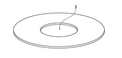
- FIG. 1 is a view showing the external shape of the magnetic disk glass substrate of the present embodiment.
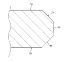
- FIG. 2 is an enlarged cross-sectional view of the outer peripheral side end face of the magnetic disk glass substrate.
- the glass substrate for a magnetic disk in this embodiment is a donut-shaped thin glass substrate in which an inner hole 2 is formed.
- the size (diameter) of the glass substrate does not matter.
- the glass substrate can be used for a nominal 1.8 to 3.5 inch size substrate, for example.
- the plate thickness is not particularly limited, and can be, for example, 0.3 to 3 mm. As shown in FIG.
- the glass substrate of the present embodiment includes a pair of main surfaces 1p, a side wall surface 1t of the glass substrate extending perpendicularly to the pair of main surfaces 1p, and between the side wall surface 1t and the main surface 1p.
- a chamfered surface 1c extending from the side wall surface 1t with an inclination to the side wall surface 1t and connected to the main surface 1p.
- a side wall surface and a chamfered surface are similarly formed on the inner peripheral side end surface of the glass substrate.
- a part or all of the chamfered surface may be formed in an arc shape in a sectional view.
- the glass substrate of the present embodiment has a shape that satisfies the following two requirements 1 and 2 with respect to the surface shape of at least one of the side wall surface and the chamfered surface.
- the end surface of the glass substrate is a mirror surface.
- the load factor of the roughness cross-sectional area is 50% in the load factor curve of the roughness cross-sectional area obtained when the surface roughness of the end surface after wet etching is 2.5 ⁇ m and wet etching is performed on the glass substrate.
- the end face of the glass substrate is provided with a roughness percentage of 40% or more.
- the end surface of the glass substrate of requirement 1 is a mirror surface when the end surface of the glass substrate is polished and the end surface reflects an image of an object like a mirror and displays an image on the surface.
- a mirror surface it is preferable that arithmetic mean roughness Ra of the surface roughness in an end surface is 0.015 micrometer or less, for example.
- the arithmetic average roughness Ra at the end face is larger than 0.015 ⁇ m, the foreign matter (fine particles) is likely to adhere to the surface by capturing the foreign matter in the concave portion on the surface.
- the maximum height Rz of the surface roughness at the end face is 0.15 ⁇ m or less.
- the maximum height Rz By setting the maximum height Rz to 0.15 ⁇ m or less, the depth of the streak-like grooves generated on the end surface becomes shallow, so that fine particles such as colloidal silica used for polishing hardly adhere (residual) to the surface. More preferably, the arithmetic average roughness Ra is 0.015 ⁇ m or less, and the maximum height Rz is preferably 0.15 ⁇ m or less.
- the roughness percentage of requirement 2 is the load factor curve of the roughness cross-sectional area of the end face (side wall surface and / or chamfered surface) described below. It is requested from.
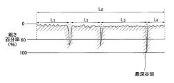
- FIG. 3 is a diagram illustrating a load factor curve of the roughness cross-sectional area of the side wall surface and / or the chamfered surface. Note that the load factor curve of the roughness cross-sectional area is also called a bearing curve.
- roughness percentage refers to the surface that forms the macroscopic shape of the surface at a certain height in the measurement result of the surface shape of the surface near the surface of the target object (or measurement data of the surface shape).
- the “roughness cross-section load factor” is the area of the cutting surface that cuts the region near the surface at a specific cutting level, that is, the area of the area near the surface of the object that exists on the cutting surface (that is, cutting) This is a value expressed as a percentage with respect to the area of the region near the surface of the object when viewed from the direction orthogonal to the surface, not the surface area along the unevenness of the surface.
- the “roughness cross-sectional area load factor” is the lengths L 1 , L 2 , L of the region that cuts the region near the surface of the object relative to the cutting length L 0 .
- FIG. 4 is a diagram for explaining the load factor of the roughness cross-sectional area.
- “Roughness cross-sectional area load factor curve” means that for the target surface vicinity area, the vertical axis is the axis of roughness percentage and the horizontal axis is the axis of the load ratio of roughness cross-sectional area. It is a curve showing the relationship.
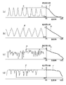
- FIGS. 5A to 5D are diagrams showing a plurality of one-dimensional surface shape waveforms c to f and load factor curves C to F of the roughness cross-sectional length obtained at this time.
- a load factor curve having a roughness cross-section length is obtained in order to obtain a load factor curve having a one-dimensional waveform.
- It is a load factor curve obtained by examining a cross-sectional area.
- the load factor curve C advances from 0% to 100% in roughness (FIG. 5).
- the load factor is a curve that gently rises (goes to the right in the horizontal axis in the figure).
- the load factor curve F has a roughness percentage.
- the load factor is a curve that rapidly increases (goes to the right in the horizontal axis in the drawing) when going from 0% to 100% (going down in the vertical axis in the drawing). As shown in FIG.
- the load factor curve D progresses from a roughness percentage of 0% to 100% (the vertical axis in the figure).
- the gradient of the increase in load factor (rightward in the horizontal axis in the figure) is a substantially constant curve, and the gradient is intermediate between the gradient of the load factor curve C and the gradient of the load factor curve F. It is. Therefore, it is possible to grasp the shape of the surface shape from the load factor curve.
- a load factor curve of the surface shape of the end surface of the glass substrate with respect to the end surface after wet etching is obtained by 2.5 ⁇ m.
- This surface shape data is obtained by measuring the surface shape of the end surface after wet etching.
- the percentage of roughness when the load factor of the roughness cross-sectional area is 50% is 40% or more.
- the roughness percentage when the load factor of the roughness cross-sectional area is 50% is 50% or more.
- the end surface of the glass substrate of the present embodiment has a surface shape in which the roughness percentage is 40% or more when the end surface of the glass substrate is wet-etched.
- the shape processing for forming the side wall surface 1t and the chamfered surface 1c (see FIG. 2) is used to determine the surface shape of the end surface of the glass substrate using the value of the roughness percentage of the surface shape of the end surface after the wet etching. This is because a latent crack is sometimes formed in the vicinity of the surface of the end face of the glass substrate, and a gap between the latent cracks is widened by wet etching, and the latent crack becomes apparent.
- the percentage of roughness when the load factor of the roughness cross-sectional area of the surface shape of the end face after wet etching is 50% is 40% or more.
- the end face after the wet etching has a surface shape as shown in FIG. 5B instead of a surface shape as shown in FIG. That is, it means that a concave portion such as a crack as shown in FIG.
- the surface shape of the end face is determined by the value of the roughness percentage when the load factor of the roughness cross-sectional area is 50%.
- the shape of the load factor curve can be known from this value, and the surface shape of the end face after wet etching is further determined. It is because it can know precisely.
- the roughness percentage when the load factor of the roughness cross-sectional area is 50% is 40% or more
- the load factor curve B When the load factor of the roughness cross-sectional area is 50%, the roughness percentage is less than 40%.
- the surface shape of the end surface showing the load curve A is close to the surface shape in which the concave portion and the convex portion are included in substantially the same ratio as shown in FIG.
- Recesses such as cracks as shown in FIGS. 5C and 5D are close to a surface shape that has developed from a substantially constant surface level at an interval.
- the requirement 2 means that even if the end face is wet etched, there are few latent cracks that appear. Therefore, in the glass substrate that satisfies the requirements 1 and 2, there is little adhesion of fine particles to the end face, and since there are few latent cracks, the latent cracks spread due to the thermal shock during the film forming process when manufacturing the magnetic disk. Even if latent cracks become apparent, few cracks have become apparent. Therefore, the occurrence of corrosion in the glass substrate is suppressed. That is, the glass substrate of the present embodiment has little trouble in recording and reproduction under the flying condition of the recording element or reproducing element with a flying distance of 1 nm or less, and can suppress a decrease in signal SN ratio.
- the alkaline earth metal component tends to elute on the surface of the glass substrate. Even if the glass substrate is made of an alkaline earth-containing glass containing such an alkaline earth metal component, the glass substrate of the present embodiment has few latent cracks, so that the occurrence of corrosion can be suppressed.
- the end face of the present embodiment is a mirror surface, and in the load factor curve of the roughness cross-sectional area of the end face after wet etching, the roughness percentage when the load factor of the roughness cross-sectional area is 50% is 40%.
- the end surface has the surface shape as described above.
- the end surface having such a surface shape is realized by adjusting processing conditions using a shape processing process and an end surface polishing process using a magnetic functional fluid, which will be described later, in the glass substrate manufacturing method described later.
- the end face polishing process is performed by bringing the polishing brush or polishing pad into contact with the end face. Since it is easily formed, requirement 2 is not satisfied.
- the magnetic functional fluid In the end surface polishing process using a magnetic functional fluid, the magnetic functional fluid is hardened by magnetism, but is more flexible in accordance with the cross-sectional shapes of the side wall surface 1t and the chamfered surface 1c of the glass substrate than a polishing brush or a polishing pad. Therefore, it is difficult to form streak-like grooves and latent cracks on the surface of the side wall surface 1t and the chamfered surface 1c as compared with the polishing brush and the polishing pad.
- the magnetic functional fluid for example, a slurry in which abrasive grains are contained in a magnetorheological fluid is preferably used.
- the roughness percentage after an etching is 60% or less.
- the percentage of roughness after etching is larger than 60%, the surface shape of the end face approaches a surface shape like a waveform c shown in FIG. 5A, and the surface is easily damaged. The cause of this is not necessarily clear, but when the percentage of roughness after etching is greater than 60%, the end surface of the glass substrate before etching is susceptible to damage such as erosion due to etching, rubbing, etc. on a wide area of the surface.
- the side wall surface 1t is in contact with the claw-shaped holding jig, whereas the chamfered surface 1c is not in contact with the holding jig, and thus is more easily damaged than the chamfered surface 1c. .
- the side wall surface 1t preferably has a surface shape that satisfies the requirement 2.
- the side wall surface 1t may be damaged by contact with a carrier or the like in the grinding / polishing process of the main surface. Furthermore, it is more preferable that the side wall surface 1t and the chamfered surface 1c of the glass substrate have a surface shape that satisfies the requirement 2. Thereby, generation
- the connecting portion between the side wall surface 1t and the chamfered surface 1c of the glass substrate may be rounded by a shape processing process or an end surface polishing process.
- the difference in the radius of curvature between adjacent measurement points is preferably 0.01 mm or less.
- variation on the periphery of an end surface shape can be suppressed. If this value is larger than 0.01 mm, fluttering may occur after being incorporated in the HDD.
- the curvature radius R of the connection part of the side wall surface 1t and the chamfered surface 1c can be calculated
- FIG. 6 is a diagram for explaining a method of obtaining the curvature radius of the cross-sectional shape of the connection portion between the side wall surface 1t and the chamfered surface 1c.
- R is the radius of a circle C2 that forms the curvature of the cross-sectional shape of the connecting portion between the side wall surface 1t and the chamfered surface 1c, and is the radius of curvature of the shape of the connecting portion.
- P1 be the intersection of an imaginary line L1 extending the straight line portion of the chamfered surface 1c and a virtual line L2 extending the straight line portion of the side wall surface 1t.
- an imaginary line L3 passing through the intersection point P1 and extending perpendicularly to the straight line portion of the chamfered surface 1c is set.
- an intersection of the connecting portion between the side wall surface 1t and the chamfered surface 1c and the virtual line L3 is defined as P2.
- a circle C1 having a predetermined radius (for example, 50 ⁇ m) around the intersection P2 is set.
- two intersections between the connecting portion between the side wall surface 1t and the chamfered surface 1c and the outer periphery of the circle C1 are defined as P3 and P4, respectively.
- a circle C2 passing through each of the three intersections P2, P3, P4 is set.
- FIG. 7 is a diagram illustrating an example of grinding performed in the present embodiment (hereinafter, this grinding is referred to as helical grinding).
- the grinding wheel 40 used for grinding the end face of the glass substrate G is formed in a cylindrical shape as a whole and has a groove 50.
- the groove 50 is formed so that both the side wall surface 1t and the chamfered surface 1c of the glass substrate G can be formed simultaneously by grinding.
- the groove 50 has a groove shape including a side wall portion 50a and chamfered portions 50b and 50b existing on both sides thereof.
- the side wall 50a and the chamfered portions 50b, 50b of the groove 50 are formed in a predetermined size and shape in consideration of the target size and shape of the ground surface of the glass substrate G.
- the glass substrate G is tilted with respect to the circumferential direction of the grooves 50 formed in the grinding wheel 40, that is, the glass with respect to the rotation axis L 40 of the grinding wheel 40.
- alpha is the angle of counterclockwise positive to.
- angle alpha the rotation axis L 1 of the substrate G in a state where only tilted, while contacting the grinding wheel 40 on the end face of the glass substrate G, a glass substrate Grinding is performed by rotating both G and the grinding wheel 40.
- the inclination angle ⁇ of the glass substrate G with respect to the groove direction of the grinding wheel 40 can be arbitrarily set. However, in order to achieve the above-described effects more effectively, it is set within a range of 1 to 15 degrees, for example. Is preferred.
- the grinding wheel 40 used for the grinding process is preferably a grindstone (resin bond grindstone) in which diamond abrasive grains are fixed by a resin (resin) or an electrodeposition plating grindstone in which diamond abrasive grains are fixed by electrodeposition plating.
- the count of the diamond grindstone is, for example, # 800 to # 3000.
- a preferable example of the peripheral speed of the grinding wheel 40 is 500 to 3000 m / min, and the peripheral speed of the glass substrate G is about 1 to 30 m / min.
- the ratio of the peripheral speed of the grinding wheel 40 to the peripheral speed of the glass substrate G is preferably in the range of 50 to 300.
- the grinding process is divided into two times, and the first grinding is performed with the rotation axis of the glass substrate G tilted by an angle ⁇ ( ⁇ > 0) as described above.
- a grinding wheel may be used in a state where the rotation axis of the glass substrate G is inclined by an angle of ⁇ , and the machining allowance for the second grinding may be adjusted to be smaller than the machining allowance for the first grinding.
- a glass blank as a material for a plate-shaped magnetic disk glass substrate having a pair of main surfaces is produced by press molding (press molding process).
- the glass blank is produced by press molding.
- a glass plate is formed by a well-known float method, redraw method, or fusion method, and a glass blank having the same shape as the glass blank is cut out from the glass plate. Good.
- a circular inner hole is formed in the central portion of the produced glass blank to form a ring-shaped (annular) glass substrate (circular hole forming process).
- the shape process which forms a chamfering surface is performed with respect to the inner peripheral end part and outer peripheral end part of the glass substrate which formed the inner hole (shape processing process). Thereby, the glass substrate in which the chamfered surface and the side wall surface are formed on the end surface is obtained.
- end-face polishing is performed on the shape-processed glass substrate (end-face polishing process). Grinding with a fixed abrasive is performed on the glass substrate that has been subjected to end surface polishing (grinding treatment). Next, 1st grinding
- the second polishing is performed on the glass substrate (second polishing process).
- ultrasonic cleaning is performed on the glass substrate after the second polishing process (ultrasonic cleaning process).
- the glass substrate for magnetic disks is obtained through the above processing.
- each process will be described in detail.
- the glass substrate for magnetic disks which satisfies the requirements 1 and 2 of this embodiment is a magnetic product which is a final product after the second polishing (final polishing) process manufactured by the method for manufacturing a glass substrate for magnetic disks.
- a glass substrate intermediate (hereinafter simply referred to as a glass substrate) that becomes the base plate of the glass substrate for a magnetic disk, which is the final product, after the end face polishing process and before the second polishing (final polishing) process Intermediate)).
- the glass substrate intermediate is a glass substrate that has been subjected to an end surface polishing process, for example, the one before the grinding process or the one that has been subjected to the grinding process but before the first polishing process.
- the grinding process and the first polishing process have been performed, but include those before the second polishing process.
- a disk-shaped glass substrate having circular holes can be obtained by forming circular inner holes using a drill or the like on a glass blank.
- (C) Shape processing In the shape processing, chamfering is performed on the end surface of the glass substrate after the circular hole formation processing. The chamfering process is performed using a grinding wheel or the like. By chamfering, a side wall surface of the substrate that extends perpendicularly to the main surface of the glass substrate on the end surface of the glass substrate, and a chamfer surface that is provided between the side wall surface and the main surface and extends at an angle to the side wall surface. Are formed. In the shape processing, the side wall surface and the chamfered surface may be formed by the above-described helical grinding. Furthermore, you may grind with a total type grindstone before helical grinding.
- the end surface polishing process In the end surface polishing process, the outer peripheral side end surface and the inner peripheral side end surface of the glass substrate are mirror-finished by an end surface polishing process using the following magnetic functional fluid.
- the magnetic functional fluid includes abrasive grains in addition to the magnetic particles.
- the glass substrate which satisfies the requirements 1 and 2 can be obtained. That is, the load factor of the roughness cross-sectional area is 50% in the load factor curve of the roughness cross-sectional area obtained when the surface roughness of the end surface after wet etching is 2.5 ⁇ m on the end surface of the glass substrate.
- the end face is polished so that the end face of the glass substrate has a surface shape with a roughness percentage of 40% or more.
- the outer peripheral side end surface has a larger area than the inner peripheral side end surface, and is exposed inside, for example, an HDD (Hard Disk Drive Device) incorporated as a magnetic disk. Therefore, when corrosion occurs on the outer peripheral side end surface, the corrosion is magnetic. The effect on the head is likely to increase.
- HDD Hard Disk Drive Device
- the end surface polishing process using a magnetic slurry is performed by the following method, for example. 8 to 11 are diagrams illustrating an example of the end surface polishing process in the present embodiment.
- the apparatus 10 for performing end face polishing polishes the end face of a glass substrate using a magnetism generating means and a magnetic functional fluid containing magnetic particles and abrasive grains.
- the outline of the apparatus 10 that performs end surface polishing will be described.
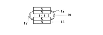
- the apparatus 10 includes a pair of magnets 12 and 14 that are permanent magnets, and a spacer 16. In the device 10, the spacer 16 is sandwiched between the magnets 12 and 14, and the device 10 has a long rotating body shape in one direction.
- the glass substrate for end face polishing is held by a holder (not shown).
- the apparatus 10 is arranged in the vicinity of the outer peripheral end face of the glass substrate held by the holder, and the mass 20 of the magnetic functional fluid (see FIGS. 10 and 11) and the outer peripheral end face of the glass substrate are brought into contact with each other.
- a holder (not shown) that holds the apparatus 10 and the glass substrate is mechanically connected to a drive motor (not shown). By driving the drive motor, as shown in FIG. 11, the apparatus 10 and the holder are rotated, and the outer peripheral side end face of the glass substrate and the lump 20 are relatively moved. Thereby, grinding
- FIG. 8 has a structure in which a spacer 16 is sandwiched between magnets 12 and 14, but may include an exterior member 18 (see FIG. 11) that covers this structure. Furthermore, the apparatus 10 can be penetrated through a circular hole provided at the center of the glass substrate, and the inner peripheral side end face of the glass substrate can be polished using the lump 20 provided on the outer periphery of the apparatus 10. Moreover, you may arrange
- the magnet 12 and the magnet 14 are close to each other and function as magnetism generating means to form a magnetic force line 19 as shown in FIG.
- the magnetic force lines 19 travel outward from the centers of the magnets 12 and 14 and travel in the thickness direction of the glass substrate.
- a magnetic slurry lump 20 as shown in FIG. In FIG. 10, the magnetic functional fluid mass 20 protrudes outward from the outer peripheral surface of the magnets 12 and 14, but the magnetic functional fluid mass 20 protrudes outward from the outer peripheral surface of the magnets 12 and 14. It does not have to protrude.
- the magnetic flux density in the magnetism generating means may be set to such an extent that the magnetic slurry lump 20 is formed.
- the end surface is efficiently polished, and the end surface has the above-mentioned surface shape.
- a permanent magnet is used as the magnetism generating means, but an electromagnet can also be used.
- the magnets 12 and 14 are fixed to an exterior member (not shown) without using the spacer 16, and the separation distance between the N pole end face of the magnet 12 and the S pole end face of the magnet 14 can be secured constant. it can.
- the magnetic functional fluid used for end face polishing includes, for example, a nonpolar oil containing 3 to 5 g / cm 3 of magnetic particles made of Fe, and a surfactant.
- a magnetorheological fluid is used.
- Nonpolar oil or polar oil has a viscosity of 100 to 1000 (mPa ⁇ sec) at room temperature (20 ° C.), for example.
- the average particle diameter d50 (diameter) of the magnetic particles is preferably 2 to 7 ⁇ m, for example.
- the lump 20 formed by the magnetic functional fluid includes abrasive grains in the lump 20 in the same manner as the magnetic particles when the magnetic functional fluid containing magnetic particles is formed as the lump 20 on the lines of magnetic force.
- the abrasive grains in the magnetic functional fluid are pushed out to a portion having a low magnetic force gradient due to the magnetic levitation effect, the abrasive grains are present in the vicinity of the end face of the glass substrate to be polished. And since it becomes a lump (hard lump) which has comparatively high elastic characteristics with a line of magnetic force, it can grind efficiently by pressing the end face of a glass substrate to lump 20. That is, the polishing rate can be increased and polishing can be performed efficiently.
- abrasive grains contained in the magnetic functional fluid known abrasive grains of glass substrates such as cerium oxide, colloidal silica, zirconia oxide, alumina abrasive grains, diamond abrasive grains, silica abrasive grains, and SiC abrasive grains may be used. it can.
- the particle size of the abrasive grains is, for example, 2 to 7 ⁇ m. By using the abrasive grains in this range, the end face polishing can be efficiently performed, and the inner peripheral side end face of the glass substrate can be satisfactorily polished.
- the abrasive grains are contained in the magnetic slurry, for example, 3 to 15 vol%.
- the magnetic functional fluid is, for example, a slurry in which abrasive grains are included in a magnetorheological fluid.
- the viscosity of the magnetic functional fluid is 1000 to 2000 (mPa ⁇ sec) at room temperature (20 ° C.) by adjusting the concentration of the magnetic viscous fluid. It is preferable in that it is performed frequently. If the viscosity is low (the concentration of the magnetorheological fluid is low), the lump 20 is difficult to form, and it is difficult to perform the relative movement while being pressed against the end face of the glass substrate 11 for polishing.
- the lump 20 has a shape recessed along the end shape of the glass substrate 11 during polishing, and is difficult to recover from the shape. Since the shape remains strong, it is difficult to form a uniform pressed state.
- the magnetic flux density in the magnetism generating means is preferably 0.3 to 2 [Tesla] from the viewpoint that the lump 20 is formed and the end face polishing is performed efficiently.
- the processing conditions include, for example, the viscosity of the magnetic functional fluid, the types of magnetic particles and abrasive grains, the particle size of the abrasive grains, the contents of the magnetomagnetic particles and abrasive grains, the magnetic flux density of the magnets 12 and 14, and the magnet 12 and 14 and at least the relative speed of the glass substrate G at the polishing position and the pressing force to the lump 20 of the glass substrate G.
- the polishing amount (removal allowance) by end face polishing is preferably 10 to 50 ⁇ m in depth from the surface (20 to 100 ⁇ m in terms of the diameter of the glass substrate). If it is less than 10 ⁇ m, there is a possibility that grinding scratches due to shape processing cannot be removed sufficiently. On the other hand, if it is larger than 50 ⁇ m, it takes too much processing time and there is a risk of deteriorating productivity. It is preferable that the depth from the surface be 20 ⁇ m (40 ⁇ m in terms of the diameter of the glass substrate) or more because it can be removed to the depth of damage (latent scratch) generated in the substrate by grinding. However, it should be noted that new damage due to the polishing process occurs at this time.
- (E) Grinding process grinding is performed on the main surface of the glass substrate using a double-sided grinding apparatus having a planetary gear mechanism. Specifically, the main surfaces on both sides of the glass substrate are ground while holding the outer peripheral side end face of the glass substrate in the holding hole provided in the holding member of the double-side grinding apparatus.
- the double-sided grinding apparatus has a pair of upper and lower surface plates (upper surface plate and lower surface plate), and a glass substrate is sandwiched between the upper surface plate and the lower surface plate. Then, either the upper surface plate or the lower surface plate, or both of them are moved, and both the main surfaces of the glass substrate are ground by moving the glass substrate and each surface plate relatively while supplying the coolant. can do.
- a grinding member in which fixed abrasive grains in which diamond is fixed with a resin is formed in a sheet shape can be mounted on a surface plate for grinding. Note that the processing order of the grinding process and the end face polishing process may be interchanged.
- the glass substrate is polished while applying a polishing slurry using a double-side polishing apparatus having the same configuration as the double-side grinding apparatus used for the above-described grinding process using fixed abrasive grains.
- a polishing slurry containing loose abrasive grains is used.
- the free abrasive grains used for the first polishing for example, abrasive grains such as cerium oxide or zirconia are used.
- the glass substrate is sandwiched between a pair of upper and lower surface plates.
- An annular flat polishing pad (for example, a resin polisher) is attached to the upper surface of the lower surface plate and the bottom surface of the upper surface plate as a whole. Then, by moving either the upper surface plate or the lower surface plate, or both, the glass substrate and each surface plate are relatively moved, thereby polishing both main surfaces of the glass substrate.
- the size of the abrasive grains is preferably in the range of 0.5 to 3 ⁇ m in terms of average particle diameter (D50).
- the glass substrate is subjected to second polishing.
- the second polishing treatment aims at mirror polishing of the main surface.
- a double-side polishing apparatus having the same configuration as the double-side polishing apparatus used for the first polishing is used. Specifically, the main surface on both sides of the glass substrate is polished while the outer peripheral side end surface of the glass substrate is held in the holding hole provided in the polishing carrier of the double-side polishing apparatus.
- the second polishing process is different from the first polishing process in that the type and particle size of the free abrasive grains are different and the hardness of the resin polisher is different.
- the hardness of the resin polisher is preferably smaller than that during the first polishing process.
- a polishing liquid containing colloidal silica as loose abrasive grains is supplied between the polishing pad of the double-side polishing apparatus and the main surface of the glass substrate, and the main surface of the glass substrate is polished.
- the size of the abrasive grains used for the second polishing is preferably in the range of 5 to 50 nm in terms of average particle diameter (d50).
- whether or not the chemical strengthening treatment is necessary may be appropriately selected in consideration of the glass composition and necessity.
- another polishing process may be added, and the polishing process of the two main surfaces may be performed by one polishing process. Moreover, you may change suitably the order of said each process.
- the present embodiment it is possible to suppress a decrease in the S / N ratio of the reproduction signal by suppressing the corrosion even under the flying condition in which the flying distance is reduced compared to the conventional case. That is, it is possible to adapt to quality requirements as a glass substrate for a magnetic disk mounted on a hard disk drive together with a DFH head (a magnetic head having a DFH function). In particular, it is suitable as a glass substrate for a magnetic disk that is mounted on a hard disk drive together with a DFH head that is equipped with an HDI sensor and can control the protruding amount of a recording / reproducing element based on a signal from the HDI sensor.
- the method for producing the glass substrate intermediate includes a process of polishing the end surface of the glass substrate containing an alkaline earth metal component as a glass composition to produce the glass substrate intermediate.
- the processing end surface after processing the glass substrate intermediate is a load factor curve of the roughness cross-sectional area obtained when measuring the surface roughness of the processing end surface after etching the processing end surface by 2.5 ⁇ m.
- the end surface of the glass substrate is polished so as to have a surface having a roughness percentage of 40% or more when the load factor of the roughness cross-sectional area is 50%.
- main surface grinding treatment for example, main surface grinding treatment, (f) first polishing treatment, or (g) chemical strengthening treatment is performed as necessary.
- first polishing treatment for example, first polishing treatment
- chemical strengthening treatment is performed as necessary.
- the glass substrate in a state after the end face polishing process and before at least (h) the second polishing (final polishing) process is referred to as a glass substrate intermediate. Therefore, after manufacturing the glass substrate intermediate, for example, when the glass substrate intermediate is transported to another place to produce a magnetic disk glass substrate, at least a polishing process (second polishing process) is performed on the main surface of the glass substrate intermediate. ), The final product glass substrate for magnetic disk can be obtained. In this case, before the second polishing process, it is preferable to perform a grinding process on the main surface, a first polishing process, or a chemical strengthening process as necessary
- the end surface of the disk-shaped glass plate was subjected to shape processing so as to have a chamfering width of 0.15 mm and a chamfering angle of 45 ° to obtain an inner peripheral side end surface and an outer peripheral side end surface, and then an end surface polishing process was performed.
- shape processing first, roughing was performed by grinding without tilting the grindstone using a general-purpose grindstone, and then finishing was performed by helical grinding with an inclination of 3 ° by changing the grindstone. Then, various end surface grinding
- the manufactured magnetic disk glass substrate is a magnetic disk glass substrate with a nominal 2.5 inch size having an outer diameter of about 65 mm, an inner diameter of about 20 mm, and a plate thickness of about 0.635 mm.
- the magnetic functional fluid used in the end surface polishing treatment is a magnetic slurry in which abrasive grains are included in a magnetorheological fluid containing magnetic particles, and has a viscosity of 1000 (mPa ⁇ sec) at room temperature (20 ° C.). did. Fe particles having an average particle diameter d50 of 2.0 ⁇ m were used as magnetic particles, and zirconia particles having an average particle diameter d50 of 0.5 ⁇ m were used as abrasive grains.
- the side wall surface and the chamfered surface of the glass substrate were polished by the method shown in FIG. 11 using a magnetic functional fluid having the same composition.
- the rotation axes of the glass substrate or the magnet are vibrated or oscillated in a direction toward or away from each other so that the force that the glass substrate G presses against the mass 20 of the magnetic functional fluid slightly vibrates or slightly swings. It was.
- the frequency and amplitude were appropriately selected and combined within a range of 1 to 50 Hz for vibration or oscillation and an amplitude (half the width of fluctuation) of 0.2 to 2 mm.
- the state of polishing of the side wall surface and the chamfered surface is slightly changed by this magnetic functional fluid, which affects the formation of latent cracks on the end surface of the glass substrate G.
- the side wall surface and the chamfered surface of the glass substrate are the same type used for the magnetic functional fluid, and abrasive grains having the same average particle diameter d50, that is, zirconia having an average particle diameter d50 of 0.5 ⁇ m. Polishing was performed using a polishing brush with a polishing slurry containing particles.
- Example 2 the side wall surface and the chamfered surface of the glass substrate were polished with a polishing slurry containing a polishing slurry of ceria particles having an average particle diameter d50 of 1.0 ⁇ m.
- the manufacturing conditions of Conventional Examples 1 and 2 are the same as those of Example 1 except for end face polishing.
- the polishing amount (removal allowance) by end face polishing was set to a depth of 20 ⁇ m from the surface (40 ⁇ m in terms of the diameter of the glass substrate) so that grinding flaws due to shape processing could be sufficiently removed in both magnetic functional fluid polishing and brush polishing.
- the end surface before the etching process of the glass substrate for magnetic disks obtained in Experimental Example 1 was a mirror surface on both the outer peripheral side wall surface and the chamfered surface including those described later.
- the side wall surface and the chamfered surface on the inner peripheral side were similarly mirror surfaces.
- the arithmetic average roughness Ra was 0.015 ⁇ m or less, and Rz was 0.15 ⁇ m or less.
- the arithmetic average roughness Ra was measured with an atomic force microscope with respect to the main plane of the glass substrate and the microwaviness ( ⁇ Wa) was measured with a scanning white interferometer, the arithmetic average roughness Ra was 0 on all the glass substrates.
- the swell ( ⁇ Wa) was 0.15 nm or less in all the glass substrates for magnetic recording media.
- the glass substrates for magnetic disks of Examples 1 to 8, Comparative Example, and Conventional Examples 1 and 2 were placed in an atmosphere of 80 ° C. and 85% humidity for 48 hours. After being allowed to stand, the presence or absence of corrosion was subjected to surface observation by SEM (scanning electron microscope) and component analysis by EDS (Energy Dispersive X-ray Spectrometry). Since the substance caused by the corrosion adhering to the end face of the glass substrate can be identified from its shape and components by the above observation and analysis, the adhesion area of the identified substance is evaluated by the surface observation by the SEM, and the occurrence of corrosion is further evaluated. The surface scratches were evaluated.
- Corrosion occurs when the side wall surface of the glass substrate is observed with 10 observations at an observation magnification of 5000 times using an SEM, and foreign matter (corrosion) containing alkaline earth metal elements of Mg, Ca, and Sr is observed in the visual field.
- the number of spots was counted and evaluated. The level was divided as follows according to the count. Levels 1 to 3 are acceptable and levels 4 and 5 are unacceptable. Level 1: 0 places where corrosion was observed Level 2: 1 place where corrosion was observed Level 3: 3 places where corrosion was observed 4: 4 places where corrosion was observed 5, 6 places Level 5: 7 or more places where corrosion was observed Table 1 shows the results.
- Example 2 The various types of glass substrates for magnetic disks (unused products) manufactured in Experimental Example 1 were annealed at 600 °, and then the same corrosion and surface scratches were evaluated as in Experimental Example 1.
- the surface shape of the end face having a roughness percentage of 40% or more when the load factor of the roughness cross-sectional area is 50% is provided as in Table 1 despite the annealing treatment.
- good corrosion suppression was observed.
- the evaluation of the scratches on the surface it was found that the generation of very thin scratches was suppressed under the condition that the roughness percentage when the load factor of the roughness cross-sectional area was 50% was 60% or less.
- Example 4 Based on the manufacturing conditions of Experimental Example 1, the surface shape of the end face before the etching process is adjusted by appropriately adjusting the processing conditions of the shape processing process and the end face polishing process using the magnetic functional fluid (Reference Examples 1 to 8). Eight types of glass substrates for magnetic disks with various modifications were produced. In addition, the adjustment of the processing conditions of the end surface polishing treatment is performed by adjusting the average particle diameter d50 and type of the abrasive grains contained in the magnetic functional fluid, and further, vibration or oscillation of the rotating shaft in the end surface polishing using the magnetic functional fluid. This was done by changing the conditions.
Landscapes
- Chemical & Material Sciences (AREA)
- Engineering & Computer Science (AREA)
- Ceramic Engineering (AREA)
- Inorganic Chemistry (AREA)
- Manufacturing & Machinery (AREA)
- Manufacturing Of Magnetic Record Carriers (AREA)
- Magnetic Record Carriers (AREA)
- Recording Or Reproducing By Magnetic Means (AREA)
- Glass Compositions (AREA)
- Surface Treatment Of Glass (AREA)
Priority Applications (6)
| Application Number | Priority Date | Filing Date | Title |
|---|---|---|---|
| US15/579,033 US10720180B2 (en) | 2015-09-30 | 2016-09-30 | Magnetic-disk glass substrate, magnetic-disk glass substrate intermediate, and method for manufacturing magnetic-disk glass substrate |
| JP2017502273A JP6106813B1 (ja) | 2015-09-30 | 2016-09-30 | 磁気ディスク用ガラス基板、磁気ディスク、ガラス基板中間体、及び磁気ディスク用ガラス基板の製造方法 |
| SG11201709624VA SG11201709624VA (en) | 2015-09-30 | 2016-09-30 | Magnetic-disk glass substrate, magnetic-disk glass substrate intermediate, and method for manufacturing magnetic-disk glass substrate |
| CN201680029894.4A CN107615381B (zh) | 2015-09-30 | 2016-09-30 | 磁盘用玻璃基板、磁盘、玻璃基板中间体和磁盘用玻璃基板的制造方法 |
| US16/884,931 US11211090B2 (en) | 2015-09-30 | 2020-05-27 | Magnetic-disk glass substrate, magnetic-disk glass substrate intermediate, and method for manufacturing magnetic-disk glass substrate |
| US17/548,008 US11710505B2 (en) | 2015-09-30 | 2021-12-10 | Magnetic-disk glass substrate, magnetic-disk glass substrate intermediate, and method for manufacturing magnetic-disk glass substrate |
Applications Claiming Priority (2)
| Application Number | Priority Date | Filing Date | Title |
|---|---|---|---|
| JP2015-195128 | 2015-09-30 | ||
| JP2015195128 | 2015-09-30 |
Related Child Applications (2)
| Application Number | Title | Priority Date | Filing Date |
|---|---|---|---|
| US15/579,033 A-371-Of-International US10720180B2 (en) | 2015-09-30 | 2016-09-30 | Magnetic-disk glass substrate, magnetic-disk glass substrate intermediate, and method for manufacturing magnetic-disk glass substrate |
| US16/884,931 Continuation US11211090B2 (en) | 2015-09-30 | 2020-05-27 | Magnetic-disk glass substrate, magnetic-disk glass substrate intermediate, and method for manufacturing magnetic-disk glass substrate |
Publications (1)
| Publication Number | Publication Date |
|---|---|
| WO2017057686A1 true WO2017057686A1 (ja) | 2017-04-06 |
Family
ID=58423694
Family Applications (1)
| Application Number | Title | Priority Date | Filing Date |
|---|---|---|---|
| PCT/JP2016/079037 Ceased WO2017057686A1 (ja) | 2015-09-30 | 2016-09-30 | 磁気ディスク用ガラス基板、磁気ディスク、ガラス基板中間体、及び磁気ディスク用ガラス基板の製造方法 |
Country Status (6)
| Country | Link |
|---|---|
| US (3) | US10720180B2 (enExample) |
| JP (2) | JP6106813B1 (enExample) |
| CN (2) | CN110503983B (enExample) |
| MY (1) | MY168096A (enExample) |
| SG (1) | SG11201709624VA (enExample) |
| WO (1) | WO2017057686A1 (enExample) |
Families Citing this family (7)
| Publication number | Priority date | Publication date | Assignee | Title |
|---|---|---|---|---|
| CN107256712B (zh) * | 2012-09-28 | 2020-04-14 | Hoya株式会社 | 磁盘用玻璃基板及其制造方法、磁盘、圆环状的玻璃基板 |
| CN110503983B (zh) * | 2015-09-30 | 2021-03-19 | Hoya株式会社 | 磁盘用玻璃基板及其制造方法、磁盘和玻璃基板中间体 |
| JP6695318B2 (ja) * | 2017-12-27 | 2020-05-20 | Hoya株式会社 | 円盤状ガラス基板の製造方法、薄板ガラス基板の製造方法、導光板の製造方法及び円盤状ガラス基板 |
| JP7533100B2 (ja) * | 2020-10-07 | 2024-08-14 | 住友金属鉱山株式会社 | ウェハーの汚染検知方法 |
| JP7467759B2 (ja) * | 2021-02-24 | 2024-04-15 | Hoya株式会社 | 磁気ディスク用基板、磁気ディスク、円環形状基板、および磁気ディスク用基板の製造方法 |
| US11270724B1 (en) | 2021-03-04 | 2022-03-08 | Western Digital Technologies, Inc. | Glass substrates for heat assisted magnetic recording (HAMR) and methods and apparatus for use with the glass substrates |
| JP7732498B2 (ja) * | 2021-03-30 | 2025-09-02 | ソニーグループ株式会社 | 磁気記録媒体 |
Citations (6)
| Publication number | Priority date | Publication date | Assignee | Title |
|---|---|---|---|---|
| JPH07244947A (ja) * | 1994-03-08 | 1995-09-19 | Hitachi Ltd | 磁気ディスク装置、磁気ディスクおよび磁気ディスクの製造方法 |
| JP2000132829A (ja) * | 1998-08-19 | 2000-05-12 | Hoya Corp | 磁気記録媒体用ガラス基板、磁気記録媒体及びそれらの製造方法 |
| JP2007042263A (ja) * | 2005-07-08 | 2007-02-15 | Showa Denko Kk | 磁気記録媒体用基板及び磁気記録媒体並びに磁気記録再生装置 |
| JP2007272995A (ja) * | 2006-03-31 | 2007-10-18 | Hoya Corp | 磁気ディスク装置および非磁性基板の良否判定方法、磁気ディスク、並びに磁気ディスク装置 |
| WO2014050241A1 (ja) * | 2012-09-28 | 2014-04-03 | Hoya株式会社 | 磁気ディスク用ガラス基板、磁気ディスク、磁気ディスク用ガラス基板の製造方法 |
| WO2015152316A1 (ja) * | 2014-03-31 | 2015-10-08 | Hoya株式会社 | 磁気ディスク用ガラス基板 |
Family Cites Families (23)
| Publication number | Priority date | Publication date | Assignee | Title |
|---|---|---|---|---|
| JPH0785463A (ja) * | 1993-09-20 | 1995-03-31 | A G Technol Kk | 磁気ディスク |
| SG84541A1 (en) | 1998-08-19 | 2001-11-20 | Hoya Corp | Glass substrate for magnetic recording medium, magnetic recording medium, and method of manufacturing the same |
| JP3959588B2 (ja) * | 1999-05-13 | 2007-08-15 | 日本板硝子株式会社 | 情報記録媒体用ガラス基板、情報記録媒体用ガラス基板の製造方法及び情報記録媒体 |
| US6509111B1 (en) * | 1999-09-24 | 2003-01-21 | Hitachi, Ltd. | Magnetic recording media and magnetic disk apparatus |
| US6706427B2 (en) * | 1999-12-21 | 2004-03-16 | Hoya Corporation | Management technique of friction coefficient based on surface roughness, substrate for information recording medium, information recording medium and manufacture method thereof |
| US6852432B2 (en) * | 2000-06-30 | 2005-02-08 | Hitachi, Ltd. | Magnetic recording media and magnetic disk apparatus |
| JP3734745B2 (ja) * | 2000-12-18 | 2006-01-11 | Hoya株式会社 | 磁気記録媒体用ガラス基板の製造方法およびそれを用いて得られる磁気記録媒体用ガラス基板 |
| JP4274708B2 (ja) * | 2001-05-14 | 2009-06-10 | Hoya株式会社 | 磁気記録媒体用ガラス基板及びその製造方法 |
| JP2005078708A (ja) * | 2003-08-29 | 2005-03-24 | Toshiba Corp | 磁気ディスクおよびこれを備えた磁気ディスク装置 |
| JP2006079800A (ja) * | 2004-08-11 | 2006-03-23 | Showa Denko Kk | 磁気記録媒体用シリコン基板及びその製造方法並びに磁気記録媒体 |
| JP2006089363A (ja) * | 2004-08-27 | 2006-04-06 | Showa Denko Kk | 磁気記録媒体用ガラス基板の製造方法、それにより得られる磁気記録媒体用ガラス基板およびこの基板を用いて得られる磁気記録媒体 |
| JP2006092722A (ja) * | 2004-08-27 | 2006-04-06 | Showa Denko Kk | 磁気ディスク用基板および磁気ディスクの製造方法 |
| WO2007007650A1 (en) * | 2005-07-08 | 2007-01-18 | Showa Denko K.K. | Substrate for magnetic recording medium, magnetic recording medium, and magnetic recording and reproducing apparatus |
| JP5484649B2 (ja) * | 2006-01-27 | 2014-05-07 | 古河電気工業株式会社 | 薄板ガラスの製造方法 |
| US8241423B2 (en) * | 2006-09-29 | 2012-08-14 | Sumco Techxiv Corporation | Silicon single crystal substrate and manufacture thereof |
| CN101977860B (zh) * | 2008-03-19 | 2013-08-21 | Hoya株式会社 | 磁记录介质基板用玻璃、磁记录介质基板、磁记录介质和它们的制造方法 |
| MY153605A (en) * | 2008-06-30 | 2015-02-27 | Hoya Corp | Substrate for magnetic disk and magnetic disk |
| JP5035405B2 (ja) | 2009-11-26 | 2012-09-26 | 旭硝子株式会社 | 磁気記録媒体用ガラス基板の製造方法 |
| KR101477469B1 (ko) * | 2012-03-30 | 2014-12-29 | 호야 가부시키가이샤 | 마스크 블랭크용 기판, 다층 반사막 부착 기판, 투과형 마스크 블랭크, 반사형 마스크 블랭크, 투과형 마스크, 반사형 마스크 및 반도체 장치의 제조 방법 |
| US9595283B2 (en) * | 2012-12-29 | 2017-03-14 | Hoya Corporation | Glass substrate for magnetic disk and magnetic disk |
| CN108847256B (zh) * | 2013-02-22 | 2020-04-03 | Hoya株式会社 | 圆环状基板、磁盘用基板及其制造方法、磁盘及其制造方法 |
| US9595286B2 (en) * | 2013-03-01 | 2017-03-14 | Hoya Corporation | Glass substrate for magnetic disk and magnetic disk |
| CN110503983B (zh) * | 2015-09-30 | 2021-03-19 | Hoya株式会社 | 磁盘用玻璃基板及其制造方法、磁盘和玻璃基板中间体 |
-
2016
- 2016-09-30 CN CN201910743784.XA patent/CN110503983B/zh active Active
- 2016-09-30 MY MYPI2017704463A patent/MY168096A/en unknown
- 2016-09-30 WO PCT/JP2016/079037 patent/WO2017057686A1/ja not_active Ceased
- 2016-09-30 US US15/579,033 patent/US10720180B2/en active Active
- 2016-09-30 SG SG11201709624VA patent/SG11201709624VA/en unknown
- 2016-09-30 CN CN201680029894.4A patent/CN107615381B/zh active Active
- 2016-09-30 JP JP2017502273A patent/JP6106813B1/ja active Active
-
2017
- 2017-03-06 JP JP2017042094A patent/JP6577501B2/ja active Active
-
2020
- 2020-05-27 US US16/884,931 patent/US11211090B2/en active Active
-
2021
- 2021-12-10 US US17/548,008 patent/US11710505B2/en active Active
Patent Citations (6)
| Publication number | Priority date | Publication date | Assignee | Title |
|---|---|---|---|---|
| JPH07244947A (ja) * | 1994-03-08 | 1995-09-19 | Hitachi Ltd | 磁気ディスク装置、磁気ディスクおよび磁気ディスクの製造方法 |
| JP2000132829A (ja) * | 1998-08-19 | 2000-05-12 | Hoya Corp | 磁気記録媒体用ガラス基板、磁気記録媒体及びそれらの製造方法 |
| JP2007042263A (ja) * | 2005-07-08 | 2007-02-15 | Showa Denko Kk | 磁気記録媒体用基板及び磁気記録媒体並びに磁気記録再生装置 |
| JP2007272995A (ja) * | 2006-03-31 | 2007-10-18 | Hoya Corp | 磁気ディスク装置および非磁性基板の良否判定方法、磁気ディスク、並びに磁気ディスク装置 |
| WO2014050241A1 (ja) * | 2012-09-28 | 2014-04-03 | Hoya株式会社 | 磁気ディスク用ガラス基板、磁気ディスク、磁気ディスク用ガラス基板の製造方法 |
| WO2015152316A1 (ja) * | 2014-03-31 | 2015-10-08 | Hoya株式会社 | 磁気ディスク用ガラス基板 |
Also Published As
| Publication number | Publication date |
|---|---|
| JP6106813B1 (ja) | 2017-04-05 |
| US20180174606A1 (en) | 2018-06-21 |
| MY168096A (en) | 2018-10-11 |
| JPWO2017057686A1 (ja) | 2017-10-05 |
| US20220101877A1 (en) | 2022-03-31 |
| US11211090B2 (en) | 2021-12-28 |
| CN107615381B (zh) | 2019-09-13 |
| CN110503983A (zh) | 2019-11-26 |
| JP6577501B2 (ja) | 2019-09-18 |
| SG11201709624VA (en) | 2017-12-28 |
| US11710505B2 (en) | 2023-07-25 |
| US20200286516A1 (en) | 2020-09-10 |
| CN110503983B (zh) | 2021-03-19 |
| JP2017130249A (ja) | 2017-07-27 |
| CN107615381A (zh) | 2018-01-19 |
| US10720180B2 (en) | 2020-07-21 |
Similar Documents
| Publication | Publication Date | Title |
|---|---|---|
| JP5860195B1 (ja) | 磁気ディスク用ガラス基板 | |
| JP5592037B1 (ja) | 磁気ディスク用ガラス基板、磁気ディスク | |
| JP6577501B2 (ja) | 磁気ディスク用ガラス基板、磁気ディスク、ガラス基板中間体、及び磁気ディスク用ガラス基板の製造方法 | |
| WO2020032146A1 (ja) | 磁気ディスク用基板及び磁気ディスク | |
| JP6156967B2 (ja) | ガラス基板の製造方法及び磁気ディスクの製造方法、並びにガラス基板の端面研磨装置 | |
| JP5870187B2 (ja) | 磁気ディスク用ガラス基板、磁気ディスク、磁気ディスクドライブ装置 | |
| JP6225248B2 (ja) | 磁気ディスク用ガラス基板、熱アシスト磁気記録用磁気ディスク、及び、熱アシスト磁気記録用磁気ディスクの製造方法 | |
| JP2015069675A (ja) | 磁気ディスク用ガラス基板の製造方法及び磁気ディスクの製造方法 | |
| JPWO2014208718A1 (ja) | 磁気ディスク用ガラス基板の製造方法、磁気ディスクの製造方法、研削砥石 | |
| WO2012090378A1 (ja) | 磁気情報記録媒体用ガラス基板の製造方法 | |
| JP2008130179A (ja) | 情報記録媒体用ガラス基板、情報記録媒体用ガラス基板の製造方法及び情報記録媒体 | |
| JP2015069687A (ja) | 磁気ディスク用ガラス基板の製造方法、磁気ディスクの製造方法 | |
| WO2011040431A1 (ja) | 磁気ディスク用ガラス基板の製造方法、及び、磁気ディスク |
Legal Events
| Date | Code | Title | Description |
|---|---|---|---|
| ENP | Entry into the national phase |
Ref document number: 2017502273 Country of ref document: JP Kind code of ref document: A |
|
| 121 | Ep: the epo has been informed by wipo that ep was designated in this application |
Ref document number: 16851855 Country of ref document: EP Kind code of ref document: A1 |
|
| WWE | Wipo information: entry into national phase |
Ref document number: 11201709624V Country of ref document: SG |
|
| WWE | Wipo information: entry into national phase |
Ref document number: 15579033 Country of ref document: US |
|
| NENP | Non-entry into the national phase |
Ref country code: DE |
|
| 122 | Ep: pct application non-entry in european phase |
Ref document number: 16851855 Country of ref document: EP Kind code of ref document: A1 |