WO2017057590A1 - 露光装置、露光方法、フラットパネルディスプレイの製造方法、及びデバイス製造方法 - Google Patents
露光装置、露光方法、フラットパネルディスプレイの製造方法、及びデバイス製造方法 Download PDFInfo
- Publication number
- WO2017057590A1 WO2017057590A1 PCT/JP2016/078851 JP2016078851W WO2017057590A1 WO 2017057590 A1 WO2017057590 A1 WO 2017057590A1 JP 2016078851 W JP2016078851 W JP 2016078851W WO 2017057590 A1 WO2017057590 A1 WO 2017057590A1
- Authority
- WO
- WIPO (PCT)
- Prior art keywords
- substrate
- unit
- support
- exposure
- exposure apparatus
- Prior art date
- Legal status (The legal status is an assumption and is not a legal conclusion. Google has not performed a legal analysis and makes no representation as to the accuracy of the status listed.)
- Ceased
Links
Images











Classifications
-
- G—PHYSICS
- G03—PHOTOGRAPHY; CINEMATOGRAPHY; ANALOGOUS TECHNIQUES USING WAVES OTHER THAN OPTICAL WAVES; ELECTROGRAPHY; HOLOGRAPHY
- G03F—PHOTOMECHANICAL PRODUCTION OF TEXTURED OR PATTERNED SURFACES, e.g. FOR PRINTING, FOR PROCESSING OF SEMICONDUCTOR DEVICES; MATERIALS THEREFOR; ORIGINALS THEREFOR; APPARATUS SPECIALLY ADAPTED THEREFOR
- G03F7/00—Photomechanical, e.g. photolithographic, production of textured or patterned surfaces, e.g. printing surfaces; Materials therefor, e.g. comprising photoresists; Apparatus specially adapted therefor
- G03F7/70—Microphotolithographic exposure; Apparatus therefor
- G03F7/70691—Handling of masks or workpieces
- G03F7/70716—Stages
- G03F7/70725—Stages control
-
- G—PHYSICS
- G03—PHOTOGRAPHY; CINEMATOGRAPHY; ANALOGOUS TECHNIQUES USING WAVES OTHER THAN OPTICAL WAVES; ELECTROGRAPHY; HOLOGRAPHY
- G03F—PHOTOMECHANICAL PRODUCTION OF TEXTURED OR PATTERNED SURFACES, e.g. FOR PRINTING, FOR PROCESSING OF SEMICONDUCTOR DEVICES; MATERIALS THEREFOR; ORIGINALS THEREFOR; APPARATUS SPECIALLY ADAPTED THEREFOR
- G03F7/00—Photomechanical, e.g. photolithographic, production of textured or patterned surfaces, e.g. printing surfaces; Materials therefor, e.g. comprising photoresists; Apparatus specially adapted therefor
- G03F7/70—Microphotolithographic exposure; Apparatus therefor
- G03F7/70691—Handling of masks or workpieces
- G03F7/70791—Large workpieces, e.g. glass substrates for flat panel displays or solar panels
-
- G—PHYSICS
- G03—PHOTOGRAPHY; CINEMATOGRAPHY; ANALOGOUS TECHNIQUES USING WAVES OTHER THAN OPTICAL WAVES; ELECTROGRAPHY; HOLOGRAPHY
- G03F—PHOTOMECHANICAL PRODUCTION OF TEXTURED OR PATTERNED SURFACES, e.g. FOR PRINTING, FOR PROCESSING OF SEMICONDUCTOR DEVICES; MATERIALS THEREFOR; ORIGINALS THEREFOR; APPARATUS SPECIALLY ADAPTED THEREFOR
- G03F7/00—Photomechanical, e.g. photolithographic, production of textured or patterned surfaces, e.g. printing surfaces; Materials therefor, e.g. comprising photoresists; Apparatus specially adapted therefor
- G03F7/20—Exposure; Apparatus therefor
-
- G—PHYSICS
- G03—PHOTOGRAPHY; CINEMATOGRAPHY; ANALOGOUS TECHNIQUES USING WAVES OTHER THAN OPTICAL WAVES; ELECTROGRAPHY; HOLOGRAPHY
- G03F—PHOTOMECHANICAL PRODUCTION OF TEXTURED OR PATTERNED SURFACES, e.g. FOR PRINTING, FOR PROCESSING OF SEMICONDUCTOR DEVICES; MATERIALS THEREFOR; ORIGINALS THEREFOR; APPARATUS SPECIALLY ADAPTED THEREFOR
- G03F7/00—Photomechanical, e.g. photolithographic, production of textured or patterned surfaces, e.g. printing surfaces; Materials therefor, e.g. comprising photoresists; Apparatus specially adapted therefor
- G03F7/70—Microphotolithographic exposure; Apparatus therefor
- G03F7/70058—Mask illumination systems
- G03F7/70141—Illumination system adjustment, e.g. adjustments during exposure or alignment during assembly of illumination system
-
- G—PHYSICS
- G03—PHOTOGRAPHY; CINEMATOGRAPHY; ANALOGOUS TECHNIQUES USING WAVES OTHER THAN OPTICAL WAVES; ELECTROGRAPHY; HOLOGRAPHY
- G03F—PHOTOMECHANICAL PRODUCTION OF TEXTURED OR PATTERNED SURFACES, e.g. FOR PRINTING, FOR PROCESSING OF SEMICONDUCTOR DEVICES; MATERIALS THEREFOR; ORIGINALS THEREFOR; APPARATUS SPECIALLY ADAPTED THEREFOR
- G03F7/00—Photomechanical, e.g. photolithographic, production of textured or patterned surfaces, e.g. printing surfaces; Materials therefor, e.g. comprising photoresists; Apparatus specially adapted therefor
- G03F7/70—Microphotolithographic exposure; Apparatus therefor
- G03F7/70216—Mask projection systems
- G03F7/70358—Scanning exposure, i.e. relative movement of patterned beam and workpiece during imaging
-
- G—PHYSICS
- G03—PHOTOGRAPHY; CINEMATOGRAPHY; ANALOGOUS TECHNIQUES USING WAVES OTHER THAN OPTICAL WAVES; ELECTROGRAPHY; HOLOGRAPHY
- G03F—PHOTOMECHANICAL PRODUCTION OF TEXTURED OR PATTERNED SURFACES, e.g. FOR PRINTING, FOR PROCESSING OF SEMICONDUCTOR DEVICES; MATERIALS THEREFOR; ORIGINALS THEREFOR; APPARATUS SPECIALLY ADAPTED THEREFOR
- G03F7/00—Photomechanical, e.g. photolithographic, production of textured or patterned surfaces, e.g. printing surfaces; Materials therefor, e.g. comprising photoresists; Apparatus specially adapted therefor
- G03F7/70—Microphotolithographic exposure; Apparatus therefor
- G03F7/70483—Information management; Active and passive control; Testing; Wafer monitoring, e.g. pattern monitoring
- G03F7/70491—Information management, e.g. software; Active and passive control, e.g. details of controlling exposure processes or exposure tool monitoring processes
- G03F7/70525—Controlling normal operating mode, e.g. matching different apparatus, remote control or prediction of failure
-
- G—PHYSICS
- G03—PHOTOGRAPHY; CINEMATOGRAPHY; ANALOGOUS TECHNIQUES USING WAVES OTHER THAN OPTICAL WAVES; ELECTROGRAPHY; HOLOGRAPHY
- G03F—PHOTOMECHANICAL PRODUCTION OF TEXTURED OR PATTERNED SURFACES, e.g. FOR PRINTING, FOR PROCESSING OF SEMICONDUCTOR DEVICES; MATERIALS THEREFOR; ORIGINALS THEREFOR; APPARATUS SPECIALLY ADAPTED THEREFOR
- G03F7/00—Photomechanical, e.g. photolithographic, production of textured or patterned surfaces, e.g. printing surfaces; Materials therefor, e.g. comprising photoresists; Apparatus specially adapted therefor
- G03F7/70—Microphotolithographic exposure; Apparatus therefor
- G03F7/70483—Information management; Active and passive control; Testing; Wafer monitoring, e.g. pattern monitoring
- G03F7/70605—Workpiece metrology
- G03F7/70616—Monitoring the printed patterns
-
- G—PHYSICS
- G03—PHOTOGRAPHY; CINEMATOGRAPHY; ANALOGOUS TECHNIQUES USING WAVES OTHER THAN OPTICAL WAVES; ELECTROGRAPHY; HOLOGRAPHY
- G03F—PHOTOMECHANICAL PRODUCTION OF TEXTURED OR PATTERNED SURFACES, e.g. FOR PRINTING, FOR PROCESSING OF SEMICONDUCTOR DEVICES; MATERIALS THEREFOR; ORIGINALS THEREFOR; APPARATUS SPECIALLY ADAPTED THEREFOR
- G03F7/00—Photomechanical, e.g. photolithographic, production of textured or patterned surfaces, e.g. printing surfaces; Materials therefor, e.g. comprising photoresists; Apparatus specially adapted therefor
- G03F7/70—Microphotolithographic exposure; Apparatus therefor
- G03F7/70691—Handling of masks or workpieces
- G03F7/70716—Stages
-
- G—PHYSICS
- G03—PHOTOGRAPHY; CINEMATOGRAPHY; ANALOGOUS TECHNIQUES USING WAVES OTHER THAN OPTICAL WAVES; ELECTROGRAPHY; HOLOGRAPHY
- G03F—PHOTOMECHANICAL PRODUCTION OF TEXTURED OR PATTERNED SURFACES, e.g. FOR PRINTING, FOR PROCESSING OF SEMICONDUCTOR DEVICES; MATERIALS THEREFOR; ORIGINALS THEREFOR; APPARATUS SPECIALLY ADAPTED THEREFOR
- G03F7/00—Photomechanical, e.g. photolithographic, production of textured or patterned surfaces, e.g. printing surfaces; Materials therefor, e.g. comprising photoresists; Apparatus specially adapted therefor
- G03F7/70—Microphotolithographic exposure; Apparatus therefor
- G03F7/70691—Handling of masks or workpieces
- G03F7/70758—Drive means, e.g. actuators, motors for long- or short-stroke modules or fine or coarse driving
-
- G—PHYSICS
- G03—PHOTOGRAPHY; CINEMATOGRAPHY; ANALOGOUS TECHNIQUES USING WAVES OTHER THAN OPTICAL WAVES; ELECTROGRAPHY; HOLOGRAPHY
- G03F—PHOTOMECHANICAL PRODUCTION OF TEXTURED OR PATTERNED SURFACES, e.g. FOR PRINTING, FOR PROCESSING OF SEMICONDUCTOR DEVICES; MATERIALS THEREFOR; ORIGINALS THEREFOR; APPARATUS SPECIALLY ADAPTED THEREFOR
- G03F7/00—Photomechanical, e.g. photolithographic, production of textured or patterned surfaces, e.g. printing surfaces; Materials therefor, e.g. comprising photoresists; Apparatus specially adapted therefor
- G03F7/70—Microphotolithographic exposure; Apparatus therefor
- G03F7/70691—Handling of masks or workpieces
- G03F7/70775—Position control, e.g. interferometers or encoders for determining the stage position
-
- G—PHYSICS
- G03—PHOTOGRAPHY; CINEMATOGRAPHY; ANALOGOUS TECHNIQUES USING WAVES OTHER THAN OPTICAL WAVES; ELECTROGRAPHY; HOLOGRAPHY
- G03F—PHOTOMECHANICAL PRODUCTION OF TEXTURED OR PATTERNED SURFACES, e.g. FOR PRINTING, FOR PROCESSING OF SEMICONDUCTOR DEVICES; MATERIALS THEREFOR; ORIGINALS THEREFOR; APPARATUS SPECIALLY ADAPTED THEREFOR
- G03F7/00—Photomechanical, e.g. photolithographic, production of textured or patterned surfaces, e.g. printing surfaces; Materials therefor, e.g. comprising photoresists; Apparatus specially adapted therefor
- G03F7/70—Microphotolithographic exposure; Apparatus therefor
- G03F7/708—Construction of apparatus, e.g. environment aspects, hygiene aspects or materials
- G03F7/70808—Construction details, e.g. housing, load-lock, seals or windows for passing light in or out of apparatus
- G03F7/70825—Mounting of individual elements, e.g. mounts, holders or supports
-
- G—PHYSICS
- G03—PHOTOGRAPHY; CINEMATOGRAPHY; ANALOGOUS TECHNIQUES USING WAVES OTHER THAN OPTICAL WAVES; ELECTROGRAPHY; HOLOGRAPHY
- G03F—PHOTOMECHANICAL PRODUCTION OF TEXTURED OR PATTERNED SURFACES, e.g. FOR PRINTING, FOR PROCESSING OF SEMICONDUCTOR DEVICES; MATERIALS THEREFOR; ORIGINALS THEREFOR; APPARATUS SPECIALLY ADAPTED THEREFOR
- G03F9/00—Registration or positioning of originals, masks, frames, photographic sheets or textured or patterned surfaces, e.g. automatically
- G03F9/70—Registration or positioning of originals, masks, frames, photographic sheets or textured or patterned surfaces, e.g. automatically for microlithography
- G03F9/7088—Alignment mark detection, e.g. TTR, TTL, off-axis detection, array detector, video detection
-
- H—ELECTRICITY
- H10—SEMICONDUCTOR DEVICES; ELECTRIC SOLID-STATE DEVICES NOT OTHERWISE PROVIDED FOR
- H10P—GENERIC PROCESSES OR APPARATUS FOR THE MANUFACTURE OR TREATMENT OF DEVICES COVERED BY CLASS H10
- H10P72/00—Handling or holding of wafers, substrates or devices during manufacture or treatment thereof
- H10P72/50—Handling or holding of wafers, substrates or devices during manufacture or treatment thereof for positioning, orientation or alignment
-
- H—ELECTRICITY
- H10—SEMICONDUCTOR DEVICES; ELECTRIC SOLID-STATE DEVICES NOT OTHERWISE PROVIDED FOR
- H10P—GENERIC PROCESSES OR APPARATUS FOR THE MANUFACTURE OR TREATMENT OF DEVICES COVERED BY CLASS H10
- H10P72/00—Handling or holding of wafers, substrates or devices during manufacture or treatment thereof
- H10P72/50—Handling or holding of wafers, substrates or devices during manufacture or treatment thereof for positioning, orientation or alignment
- H10P72/57—Mask-wafer alignment
-
- H—ELECTRICITY
- H10—SEMICONDUCTOR DEVICES; ELECTRIC SOLID-STATE DEVICES NOT OTHERWISE PROVIDED FOR
- H10P—GENERIC PROCESSES OR APPARATUS FOR THE MANUFACTURE OR TREATMENT OF DEVICES COVERED BY CLASS H10
- H10P72/00—Handling or holding of wafers, substrates or devices during manufacture or treatment thereof
- H10P72/70—Handling or holding of wafers, substrates or devices during manufacture or treatment thereof for supporting or gripping
-
- G—PHYSICS
- G03—PHOTOGRAPHY; CINEMATOGRAPHY; ANALOGOUS TECHNIQUES USING WAVES OTHER THAN OPTICAL WAVES; ELECTROGRAPHY; HOLOGRAPHY
- G03F—PHOTOMECHANICAL PRODUCTION OF TEXTURED OR PATTERNED SURFACES, e.g. FOR PRINTING, FOR PROCESSING OF SEMICONDUCTOR DEVICES; MATERIALS THEREFOR; ORIGINALS THEREFOR; APPARATUS SPECIALLY ADAPTED THEREFOR
- G03F7/00—Photomechanical, e.g. photolithographic, production of textured or patterned surfaces, e.g. printing surfaces; Materials therefor, e.g. comprising photoresists; Apparatus specially adapted therefor
- G03F7/0005—Production of optical devices or components in so far as characterised by the lithographic processes or materials used therefor
- G03F7/0007—Filters, e.g. additive colour filters; Components for display devices
-
- G—PHYSICS
- G03—PHOTOGRAPHY; CINEMATOGRAPHY; ANALOGOUS TECHNIQUES USING WAVES OTHER THAN OPTICAL WAVES; ELECTROGRAPHY; HOLOGRAPHY
- G03F—PHOTOMECHANICAL PRODUCTION OF TEXTURED OR PATTERNED SURFACES, e.g. FOR PRINTING, FOR PROCESSING OF SEMICONDUCTOR DEVICES; MATERIALS THEREFOR; ORIGINALS THEREFOR; APPARATUS SPECIALLY ADAPTED THEREFOR
- G03F7/00—Photomechanical, e.g. photolithographic, production of textured or patterned surfaces, e.g. printing surfaces; Materials therefor, e.g. comprising photoresists; Apparatus specially adapted therefor
- G03F7/26—Processing photosensitive materials; Apparatus therefor
- G03F7/30—Imagewise removal using liquid means
Definitions
- the present invention relates to an exposure apparatus, an exposure method, a flat panel display manufacturing method, and a device manufacturing method.
- a mask or reticle such as liquid crystal display elements and semiconductor elements (such as integrated circuits)
- a glass plate or a wafer hereinafter referred to as “mask”.
- substrate Collectively referred to as a “substrate”)
- step-and-scan type exposure apparatus so-called “so-called” that transfers a pattern formed on a mask onto a substrate using an energy beam while moving in synchronization along a predetermined scanning direction. Scanning steppers (also called scanners)) are used.
- the substrate holder that holds the substrate in order to position the substrate at high speed and with high accuracy, is arranged in three degrees of freedom in the horizontal plane (scanning direction, cross-scanning direction, and rotational direction in the horizontal plane).
- a device that is finely driven is known (see, for example, Patent Document 1).
- the substrate holder With the recent increase in size of the substrate, the substrate holder becomes larger and heavier, which tends to make it difficult to control the positioning of the substrate.
- exposure is performed by irradiating an object with illumination light via an optical system, and driving the object relative to the illumination light to scan and expose a plurality of regions of the object, respectively.
- a first support unit configured to contactlessly support a first region of the plurality of regions and at least a part of a second region provided alongside the first region in the first direction;
- a holding unit that holds the object that is supported in a non-contact manner by the first support unit at a position that does not overlap the first support unit with respect to a second direction that intersects the first direction; and the first support with respect to the second direction.
- the holding portion that holds the object is arranged with respect to the first support portion so that the other portion of the second region is supported by the first support portion.
- An exposure apparatus comprising: a first drive unit that is relatively driven in a direction; It is provided.
- an exposure apparatus that irradiates an object with illumination light, moves the object relative to the illumination light in a first direction, and scans and exposes a plurality of regions of the object.
- the first support part that non-contact supports at least the first area of the plurality of areas, the holding part that holds the object that is non-contact supported by the support part, and the holding part.
- a second drive system that drives relative to the support portion such that a part of the first region is separated from the support portion with respect to one direction of one direction and a second direction that intersects the first direction;
- An exposure apparatus is provided that includes a second drive system that drives the support portion in the other direction.
- an exposure apparatus that irradiates an object with illumination light through an optical system, drives the object with respect to the illumination light, and scans and exposes the object.
- a first support part that supports the entire surface of the object in a non-contact manner, a holding part that holds the object that is supported in a non-contact manner by the first support part, and drives the holding part relative to the first support part.
- a drive unit wherein the drive unit holds the object that holds the object supported almost entirely on the first support unit, and a part of the object is detached from the first support unit.
- an exposure apparatus that is relatively driven with respect to a region irradiated with the illumination light in the object.
- a flat including exposing the object using the exposure apparatus according to any one of the first to third aspects and developing the exposed object.
- a method for manufacturing a panel display is provided.
- a device including exposing the object using the exposure apparatus according to any one of the first to third aspects, and developing the exposed object.
- a manufacturing method is provided.
- exposure is performed by irradiating an object with illumination light via an optical system, and driving the object relative to the illumination light to scan and expose a plurality of regions of the object, respectively.
- It is a method, Comprising: A 1st support part and the at least one part area
- the holding portion that holds the object is supported by the first support portion so that the other region of the second region is supported by the first support portion by the first driving portion that is disposed apart from the first support portion. Relative driving in the first direction with respect to the first support part
- the exposure method comprising a Rukoto, a is provided.
- an exposure method of irradiating an object with illumination light, moving the object relative to the illumination light in a first direction, and scanning and exposing a plurality of regions of the object respectively.
- an exposure method in which an object is irradiated with illumination light via an optical system, the object is driven with respect to the illumination light, and the object is scanned and exposed.
- the holding unit that holds the object that is substantially non-contact-supported by the first support unit, and a part of the object is the first
- An exposure method is provided that relatively drives a region of the object that is irradiated with the illumination light so as to be separated from the support unit.
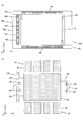
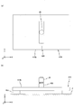
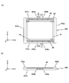
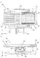
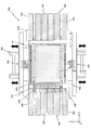
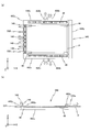
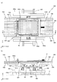
- FIG. 2 is a sectional view taken along line AA in FIG. 1. It is a figure which shows the detail of the substrate stage apparatus with which the liquid-crystal exposure apparatus of FIG. 1 is provided. It is a principal part enlarged view of a substrate stage apparatus. It is a conceptual diagram of the board
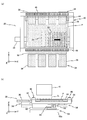
- FIGS. 7A and 7B are views (a plan view and a front view, respectively) for explaining the operation (part 1) of the substrate stage apparatus during the exposure operation.
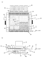
- FIGS. 8A and 8B are views (a plan view and a front view, respectively) for explaining the operation (part 2) of the substrate stage apparatus during the exposure operation.
- FIGS. 9A and 9B are views (a plan view and a front view, respectively) for explaining the operation (part 3) of the substrate stage apparatus during the exposure operation.
- FIGS. 10A and 10B are views (a plan view and a front view, respectively) showing a substrate carrier according to a first modification of the first embodiment. It is a figure which shows the substrate stage apparatus which concerns on the 2nd modification of 1st Embodiment.
- FIG. 10A and 10B are views (a plan view and a front view, respectively) showing a substrate carrier according to a first modification of the first embodiment. It is a figure which shows the substrate stage apparatus which concerns on the 2nd modification of 1st Embodiment
- FIGS. 12A is a plan view of a substrate carrier according to the second modification
- FIG. 12B is a plan view of a substrate table according to the second modification
- FIGS. 13A and 13B are views (a plan view and a sectional view, respectively) showing a substrate stage device according to a third modification of the first embodiment. It is a figure which shows the substrate stage apparatus which concerns on 2nd Embodiment.
- FIGS. 15A and 15B are views (a plan view and a side view, respectively) showing a Y guide bar, a weight cancellation device, and the like included in the substrate stage apparatus of FIG. 16A and 16B are views (a plan view and a side view, respectively) showing a base frame, a coarse movement stage, and the like included in the substrate stage apparatus of FIG.
- FIGS. 17A and 17B are views (a plan view and a side view, respectively) showing a non-contact holder, an auxiliary table, and the like included in the substrate stage apparatus of FIG. 18A and 18B are views (a plan view and a side view, respectively) showing the substrate carrier and the like included in the substrate stage apparatus of FIG.
- FIG. 19A and FIG. 19B are views (a plan view and a side view, respectively) for explaining the operation at the time of scan exposure of the substrate stage apparatus according to the second embodiment.
- 20A and 20B are views (No. 1 and No. 2) for explaining the Y step operation of the substrate stage apparatus according to the second embodiment. It is a figure which shows the substrate stage apparatus which concerns on the modification (4th modification) of 2nd Embodiment.
- FIGS. 23A and 23B are views (a plan view and a side view, respectively) showing a base frame, a coarse movement stage, and the like included in the substrate stage apparatus of FIG. 24A and 24B are views (a plan view and a side view, respectively) showing a non-contact holder, an auxiliary table, and the like included in the substrate stage apparatus of FIG. 25A and 25B are views (a plan view and a side view, respectively) showing a substrate carrier and the like included in the substrate stage apparatus of FIG.
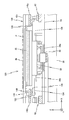
- FIG. 26A is a diagram for explaining the substrate stage apparatus according to the fourth modification when the substrate is unloaded
- FIG. 26B is a cross-sectional view taken along the line BB of FIG. is there.
- FIG. 1 schematically shows a configuration of a liquid crystal exposure apparatus 10 according to the first embodiment.
- the liquid crystal exposure apparatus 10 employs a step-and-scan method in which a rectangular (square) glass substrate P (hereinafter simply referred to as a substrate P) used in, for example, a liquid crystal display device (flat panel display) is an exposure object.
- a projection exposure apparatus a so-called scanner.
- the liquid crystal exposure apparatus 10 includes an illumination system 12, a mask stage 14 that holds a mask M on which a pattern such as a circuit pattern is formed, a projection optical system 16, an apparatus body 18, and a surface (a surface facing the + Z side in FIG. 1). It has a substrate stage device 20 that holds a substrate P coated with a resist (sensitive agent), a control system for these, and the like.
- the direction in which the mask M and the substrate P are relatively scanned with respect to the projection optical system 16 at the time of exposure is defined as the X-axis direction
- the direction orthogonal to the X-axis in the horizontal plane is defined as the Y-axis direction, the X-axis, and the Y-axis.
- the illumination system 12 is configured similarly to the illumination system disclosed in, for example, US Pat. No. 5,729,331. That is, the illumination system 12 emits light emitted from a light source (not shown) (for example, a mercury lamp) through exposure mirrors (not shown), dichroic mirrors, shutters, wavelength selection filters, various lenses, and the like. Irradiation light) is applied to the mask M as IL.
- a light source for example, a mercury lamp
- Irradiation light is applied to the mask M as IL.
- the illumination light IL for example, light such as i-line (wavelength 365 nm), g-line (wavelength 436 nm), h-line (wavelength 405 nm), or the combined light of the i-line, g-line, and h-line is used.
- the mask stage 14 holds a light transmission type mask M.
- the main controller 50 moves the mask stage 14 (that is, the mask M) to the illumination system 12 (illumination light IL) via a mask stage drive system 52 (see FIG. 6) including, for example, a linear motor. While driving with a predetermined long stroke in the X-axis direction (scan direction), it is slightly driven in the Y-axis direction and the ⁇ z direction.
- the position information of the mask stage 14 in the horizontal plane is obtained by a mask stage position measurement system 54 (see FIG. 6) including a laser interferometer, for example.
- the projection optical system 16 is disposed below the mask stage 14.
- the projection optical system 16 is a so-called multi-lens type projection optical system having the same configuration as the projection optical system disclosed in, for example, US Pat. No. 6,552,775, and forms, for example, an erect image. It has multiple optical systems that are telecentric on both sides.
- the optical axis AX of the illumination light IL projected from the projection optical system 16 onto the substrate P is substantially parallel to the Z axis.
- the illumination light IL that has passed through the mask M is illuminated via the projection optical system 16.
- a projection image (partial pattern image) of the pattern of the mask M in the region is formed in the exposure region on the substrate P.
- the mask M moves relative to the illumination area (illumination light IL) in the scanning direction
- the substrate P moves relative to the exposure area (illumination light IL) in the scanning direction.
- One shot area is scanned and exposed, and the pattern formed on the mask M (the entire pattern corresponding to the scanning range of the mask M) is transferred to the shot area.
- the illumination area on the mask M and the exposure area (illumination light irradiation area) on the substrate P are optically conjugate with each other by the projection optical system 16.
- the apparatus main body 18 is a part that supports the mask stage 14 and the projection optical system 16, and is installed on the floor F of the clean room via a plurality of vibration isolation devices 18d.
- the apparatus main body 18 is configured in the same manner as the apparatus main body disclosed in, for example, US Patent Application Publication No. 2008/0030702, and an upper base 18a (also referred to as an optical surface plate or the like) that supports the projection optical system 16. 1), a pair of the undercarriage portions 18b (in FIG. 1, one is not shown because it overlaps in the depth direction of the paper surface, see FIG. 2), and a pair of the undercarriage portions 18c.
- the substrate stage device 20 is a part that positions the substrate P with high precision with respect to the projection optical system 16 (illumination light IL), and has a predetermined long stroke along the horizontal plane (X-axis direction and Y-axis direction). And is slightly driven in the direction of 6 degrees of freedom.
- the substrate stage device 20 includes a base frame 22, a coarse movement stage 24, a weight cancellation device 26, an X guide bar 28, a substrate table 30, a non-contact holder 32, a pair of auxiliary tables 34, a substrate carrier 40, and the like.
- the base frame 22 includes a pair of X beams 22a.
- the X beam 22a is made of a member having a rectangular YZ section extending in the X axis direction.
- the pair of X beams 22a are arranged at predetermined intervals in the Y-axis direction, and are installed on the floor F in a state of being physically separated (vibrated and insulated) from the apparatus main body 18 via the leg portions 22b.
- the pair of X beams 22a and the leg portions 22b are integrally connected by connecting members 22c.
- the coarse movement stage 24 is a portion for driving the substrate P with a long stroke in the X-axis direction, and includes a pair of X carriages 24a corresponding to the pair of X beams 22a.
- the X carriage 24a is formed in an inverted L-shaped YZ section, and is placed on the corresponding X beam 22a via a plurality of mechanical linear guide devices 24c.
- Each of the pair of X carriages 24a corresponds by the main controller 50 (see FIG. 6) via an X linear actuator that is a part of the substrate table drive system 56 (see FIG. 6) for driving the substrate table 30. It is synchronously driven along the X beam 22a with a predetermined long stroke in the X axis direction (about 1 to 1.5 times the length of the substrate P in the X axis direction).
- the type of the X linear actuator for driving the X carriage 24a can be changed as appropriate.
- a linear motor 24d including a mover included in the X carriage 24a and a stator included in the corresponding X beam 22a.
- the present invention is not limited to this.
- a feed screw (ball screw) device or the like can also be used.
- the coarse movement stage 24 has a pair of Y stators 62a.
- the Y stator 62a is made of a member extending in the Y-axis direction (see FIG. 1).
- One Y stator 62a is near the + X side end of the coarse movement stage 24, and the other Y stator 62a is near the -X side end of the coarse movement stage 24, respectively, on the pair of X carriages 24a. (See FIG. 1).
- the function of the Y stator 62a will be described later.
- the weight canceling device 26 is inserted between the pair of X carriages 24a of the coarse movement stage 24, and supports the weight of the system including the substrate table 30 and the non-contact holder 32 from below.
- the details of the weight cancellation device 26 are disclosed in, for example, US Patent Application Publication No. 2010/0018950, and thus the description thereof is omitted.
- the weight cancellation device 26 is mechanically connected to the coarse motion stage 24 via a plurality of connection devices 26a (also referred to as flexure devices) extending radially from the weight cancellation device 26, and the coarse motion stage. By being pulled by 24, it moves in the X-axis direction integrally with the coarse movement stage 24.
- the weight canceling device 26 is connected to the coarse movement stage 24 via a connecting device 26a extending radially from the weight canceling device 26. However, since the weight canceling device 26 moves only in the X-axis direction, the connecting device extends in the X direction.
- the configuration may be such that it is connected to the coarse movement stage 24 by 26a.
- the X guide bar 28 is a part that functions as a surface plate when the weight cancellation device 26 moves.
- the X guide bar 28 is composed of a member extending in the X-axis direction, and is inserted between a pair of X beams 22a included in the base frame 22 as shown in FIG. It is fixed to. With respect to the Y-axis direction, the center of the X guide bar 28 substantially coincides with the center of the exposure region generated on the substrate P by the illumination light IL.
- the upper surface of the X guide bar 28 is set parallel to the XY plane (horizontal plane).
- the weight cancellation device 26 is placed on the X guide bar 28 in a non-contact state via, for example, an air bearing 26b. When the coarse movement stage 24 moves on the base frame 22 in the X-axis direction, the weight cancellation device 26 moves on the X guide bar 28 in the X-axis direction.
- the substrate table 30 is made of a rectangular plate (or box-shaped) member whose longitudinal direction is the X-axis direction in plan view, and as shown in FIG. 2, the center portion is XY plane via a spherical bearing device 26 c.
- the weight cancellation device 26 is supported in a non-contact manner from below in a swingable manner.
- a pair of auxiliary tables 34 (not shown in FIG. 2) are connected to the substrate table 30. The function of the pair of auxiliary tables 34 will be described later.
- the substrate table 30 is a part of the substrate table drive system 56 (see FIG. 6), and includes a plurality of linear elements including a stator that the coarse movement stage 24 has and a mover that the substrate table 30 itself has.
- a direction intersecting a horizontal plane (XY plane) with respect to coarse movement stage 24 by motor 30a for example, a voice coil motor
- motor 30a for example, a voice coil motor
- Z tilt direction a Z tilt direction
- the substrate table 30 is mechanically connected to the coarse movement stage 24 via a plurality of connection devices 30b (flexure devices) extending radially from the substrate table 30.
- the connection device 30b includes, for example, a ball joint, and does not hinder relative movement of the substrate table 30 with respect to the coarse movement stage 24 in a minute stroke in the Z tilt direction. Further, when the coarse movement stage 24 moves in the X-axis direction with a long stroke, the coarse movement stage 24 and the substrate table 30 are pulled by the coarse movement stage 24 through the plurality of connection devices 30b. , Move in the X-axis direction integrally.
- the coarse movement stage 24 is not connected via the connection devices 30b extending in a radial direction with respect to the coarse movement stage 24 but via a plurality of connection devices 30b parallel to the X-axis direction. You may make it connect to.
- the non-contact holder 32 is made of a rectangular plate-shaped (or box-shaped) member whose longitudinal direction is the X-axis direction in plan view, and supports the substrate P from below on its upper surface.
- the non-contact holder 32 has a function of preventing sagging and wrinkles from occurring on the substrate P (correcting the plane).
- the non-contact holder 32 is fixed to the upper surface of the substrate table 30 and moves with a long stroke in the X-axis direction integrally with the substrate table 30 and moves slightly in the Z tilt direction.
- the length of each of the four sides on the upper surface (substrate support surface) of the non-contact holder 32 is set to be substantially the same as the length of each of the four sides of the substrate P (actually slightly shorter). Therefore, the non-contact holder 32 supports substantially the entire substrate P from below, specifically, an exposure target region on the substrate P (region excluding a blank region formed near the end of the substrate P). Support is possible from below.
- the non-contact holder 32 is connected to a pressurized gas supply device (not shown) installed outside the substrate stage device 20 and a vacuum suction device via a piping member such as a tube.
- a plurality of minute holes communicating with the piping member are formed on the upper surface (substrate placement surface) of the non-contact holder 32.
- the non-contact holder 32 floats the substrate P by ejecting pressurized gas (for example, compressed air) supplied from the pressurized gas supply device to the lower surface of the substrate P through (a part of) the hole. .
- pressurized gas for example, compressed air
- a load acts on the substrate P, and the plane is corrected along the upper surface of the non-contact holder 32.
- a load acts on the substrate P, and the plane is corrected along the upper surface of the non-contact holder 32.
- a gap is formed between the substrate P and the non-contact holder 32, the relative movement of the substrate P and the non-contact holder 32 in the direction parallel to the horizontal plane is not hindered.
- the substrate carrier 40 is a part that holds the substrate P, and the substrate P is arranged in three-degree-of-freedom directions (X-axis direction, Y-axis direction, and ⁇ z direction) in a horizontal plane with respect to the illumination light IL (see FIG. 1). Move.
- the substrate carrier 40 is formed in a rectangular frame shape (frame shape) in plan view, and holds the region (blank region) near the end (outer peripheral edge) of the substrate P in the non-contact holder 32. On the other hand, it moves along the XY plane. Details of the substrate carrier 40 will be described below with reference to FIG.
- the substrate carrier 40 includes a pair of X frames 42x and a pair of Y frames 42y, as shown in FIG.
- the pair of X frames 42x are each composed of a flat plate-like member extending in the X-axis direction, and are arranged in the Y-axis direction at a predetermined interval (wider than the dimension of the substrate P and the non-contact holder 32 in the Y-axis direction).
- the pair of Y frames 42y are each formed of a flat plate-like member extending in the Y-axis direction, and are arranged at predetermined intervals (wider than the dimensions of the substrate P and the non-contact holder 32 in the X-axis direction) in the X-axis direction. ing.
- the + X side Y frame 42y is connected to the lower surface in the vicinity of the + X side end portion of each of the pair of X frames 42x via a spacer 42a.
- the ⁇ X side Y frame 42y is connected to the lower surface in the vicinity of the ⁇ X side end of each of the pair of X frames 42x via a spacer 42a.
- the height position (position in the Z-axis direction) of the upper surface of the pair of Y frames 42y is set lower ( ⁇ Z side) than the height position of the lower surface of the pair of X frames 42x.
- a pair of suction pads 44 are attached to the lower surfaces of the pair of X frames 42x so as to be separated from each other in the X-axis direction.
- the substrate carrier 40 has, for example, four suction pads 44 in total.
- the suction pad 44 is disposed so as to protrude from the surface where the pair of X frames 42x face each other in a direction facing each other (inside the substrate carrier 40).
- the four suction pads 44 are positioned in the horizontal plane (X frame) so that the vicinity of the four corners (blank area) of the substrate P can be supported from below with the substrate P inserted between the pair of X frames 42x.
- the attachment position with respect to 42x is set.
- a vacuum suction device (not shown) is connected to each of the four suction pads 44.
- the suction pad 44 sucks and holds the lower surface of the substrate P by the vacuum suction force supplied from the vacuum suction device.
- the number of suction pads 44 is not limited to this, and can be changed as appropriate.
- the substrate P is supported from below by the suction pads 44 of the substrate carrier 40 (adsorption holding). ), And almost the entire surface including the central portion is non-contact supported by the non-contact holder 32 from below.
- the + X side and ⁇ X side ends of the substrate P protrude from the + X side and ⁇ X side ends of the non-contact holder 32, respectively.
- four suction pads 44 (partially in FIG. 2) (Not shown) sucks and holds the portion of the substrate P protruding from the non-contact holder 32. That is, the attachment position for the X frame 42x is set so that the suction pad 44 is positioned outside the non-contact holder 32 in the X-axis direction.
- the substrate carrier driving system 60 (see FIG. 6) for driving the substrate carrier 40 will be described.
- the main controller 50 (see FIG. 6) drives the substrate carrier 40 with a long stroke in the Y-axis direction with respect to the non-contact holder 32 via the substrate carrier drive system 60, and in the horizontal plane. Micro drive in the direction of 3 degrees of freedom.
- the main controller 50 integrally connects the non-contact holder 32 and the substrate carrier 40 in the X-axis direction via the above-described substrate table drive system 56 (see FIG. 6) and the substrate carrier drive system 60 ( Drive in sync).
- the substrate carrier drive system 60 includes a Y stator 62a included in the coarse movement stage 24 and a Y mover that generates thrust in the Y-axis direction in cooperation with the Y stator 62a.
- a pair of Y linear actuators 62 including 62b is provided.
- a Y stator 64a and an X stator 66a are attached to the Y mover 62b of each of the pair of Y linear actuators 62.
- the Y stator 64a constitutes a Y voice coil motor 64 that applies thrust in the Y-axis direction to the substrate carrier 40 in cooperation with the Y mover 64b attached to the substrate carrier 40 (the lower surface of the Y frame 42y).
- the X stator 66a constitutes an X voice coil motor 66 that applies thrust in the X-axis direction to the substrate carrier 40 in cooperation with the X mover 66b attached to the substrate carrier 40 (the lower surface of the Y frame 42y). is doing.
- the substrate stage apparatus 20 has one Y voice coil motor 64 and one X voice coil motor 66 on each of the + X side and the ⁇ X side of the substrate carrier 40.
- the Y voice coil motor 64 and the X voice coil motor 66 are arranged point-symmetrically around the position of the center of gravity of the substrate P, respectively. Accordingly, when thrust is applied to the substrate carrier 40 in the X-axis direction by using the X voice coil motor 66 on the + X side of the substrate carrier 40 and the X voice coil motor 66 on the ⁇ X side of the substrate carrier 40, It is possible to obtain the same effect as when a thrust is applied to the position of the center of gravity in parallel with the X-axis direction, that is, to prevent the moment in the ⁇ z direction from acting on the substrate carrier 40 (substrate P).
- the pair of Y voice coil motors 64 are arranged with the center of gravity (line) of the substrate P in the X-axis direction interposed therebetween, so that no moment in the ⁇ z direction acts on the substrate carrier 40.
- the substrate carrier 40 is moved to the coarse movement stage 24 (that is, the non-contact holder 32) by the main controller 50 (see FIG. 6) via the pair of Y voice coil motors 64 and the pair of X voice coil motors 66. Is slightly driven in the direction of three degrees of freedom in the horizontal plane. Further, when the coarse movement stage 24 (that is, the non-contact holder 32) moves in a long stroke in the X-axis direction, the main controller 50 causes the non-contact holder 32 and the substrate carrier 40 to be integrally extended in the X-axis direction. A thrust in the X-axis direction is applied to the substrate carrier 40 by using the pair of X voice coil motors 66 so as to move in a stroke.
- the main controller 50 uses the pair of Y linear actuators 62 and the pair of Y voice coil motors 64 to move the substrate carrier 40 with respect to the non-contact holder 32 in a long stroke in the Y-axis direction. Move the relative position with. More specifically, the main controller 50 moves the Y mover 62b of the pair of Y linear actuators 62 in the Y-axis direction, and includes a Y voice coil including a Y stator 64a attached to the Y mover 62b. A thrust in the Y-axis direction is applied to the substrate carrier 40 using the motor 64. Accordingly, the substrate carrier 40 moves with a long stroke in the Y-axis direction independently (separated) from the non-contact holder 32.
- the substrate carrier 40 that holds the substrate P moves in a long stroke integrally with the non-contact holder 32 in the X axis (scanning) direction, and the Y axis direction. With respect to, it moves with a long stroke independently of the non-contact holder 32.
- the Z position of the suction pad 44 and the Z position of the non-contact holder 32 partially overlap, but the substrate carrier 40 moves relative to the non-contact holder 32 with a long stroke. Since only the Y-axis direction is performed, there is no possibility that the suction pad 44 and the non-contact holder 32 come into contact with each other.
- the substrate table 30 that is, the non-contact holder 32
- the substrate P that has been flattened on the non-contact holder 32 changes its posture in the Z tilt direction together with the non-contact holder 32.
- the substrate carrier 40 that sucks and holds P changes its posture in the Z tilt direction together with the substrate P. Note that the posture of the substrate carrier 40 may not be changed by the elastic deformation of the suction pad 44.
- the pair of auxiliary tables 34 are held by the substrate carrier 40 in cooperation with the non-contact holder 32 when the substrate carrier 40 separates from the non-contact holder 32 and moves relative to the Y-axis direction. It is a device that supports the lower surface of the substrate P. As described above, since the substrate carrier 40 moves relative to the non-contact holder 32 while holding the substrate P, for example, when the substrate carrier 40 moves in the + Y direction from the state shown in FIG. The vicinity of the + Y side end of the contact is not supported by the non-contact holder 32.
- the substrate P is supported from below by using one of the pair of auxiliary tables 34 in order to suppress bending due to the weight of the portion of the substrate P that is not supported by the non-contact holder 32.
- the pair of auxiliary tables 34 have substantially the same structure except that they are arranged symmetrically on the paper surface.
- the auxiliary table 34 has a plurality of air levitation units 36 as shown in FIG.
- the air levitation unit 36 is formed in a rod shape extending in the Y-axis direction, and a plurality of air levitation units 36 are arranged at predetermined intervals in the X-axis direction.
- the shape, number, arrangement, and the like are not particularly limited as long as the resulting deflection can be suppressed.
- the plurality of air levitation units 36 are supported from below by arm-shaped support members 36 a protruding from the side surface of the substrate table 30.
- a minute gap is formed between the plurality of air levitation units 36 and the non-contact holder 32.
- the height position of the upper surface of the air levitation unit 36 is set to be substantially the same (or somewhat lower) as the height position of the upper surface of the non-contact holder 32.
- the air levitation unit 36 supports the substrate P in a non-contact manner by ejecting gas (for example, air) from its upper surface to the lower surface of the substrate P.
- gas for example, air
- the non-contact holder 32 described above applies a preload to the substrate P to correct the surface of the substrate P.
- the air levitation unit 36 only needs to be able to suppress the deflection of the substrate P, and therefore simply the substrate P.
- the gas may be supplied only to the lower surface of the substrate, and the height position of the substrate P on the air levitation unit 36 may not be particularly managed.
- the substrate position measurement system obtains position information in a direction intersecting the horizontal plane of the substrate table 30 (position information in the Z-axis direction, rotation amount information in the ⁇ x and ⁇ y directions, hereinafter referred to as “Z tilt position information”).
- Z tilt position information position information in a direction intersecting the horizontal plane of the substrate table 30
- a position in the horizontal plane for obtaining the tilt position measurement system 58 see FIG. 6
- position information position information in the X-axis direction and Y-axis direction, and rotation amount information in the ⁇ z direction
- a measurement system 70 see FIG. 6).
- the Z tilt position measurement system 58 is a plurality of (at least three) laser displacement meters fixed on the lower surface of the substrate table 30 and around the spherical bearing device 26c. 58a.
- the laser displacement meter 58a irradiates the target 58b fixed to the casing of the weight canceling device 26 with measurement light and receives the reflected light, whereby the Z axis of the substrate table 30 at the measurement light irradiation point is received.
- the direction displacement information is supplied to the main controller 50 (see FIG. 6).
- At least three laser displacement meters 58a are arranged at three places (for example, positions corresponding to the vertices of an equilateral triangle) that are not on the same straight line, and the main controller 50 includes the at least three laser displacement meters 58a.
- the Z tilt position information of the substrate table 30 (that is, the substrate P) is obtained. Since the weight cancellation device 26 moves along the upper surface (horizontal plane) of the X guide bar 28, the main control device 50 measures the posture change of the substrate table 30 with respect to the horizontal plane regardless of the X position of the substrate table 30. Can do.
- the horizontal plane position measurement system 70 (see FIG. 6) has a pair of head units 72 as shown in FIG. One head unit 72 is disposed on the ⁇ Y side of the projection optical system 16, and the other head unit 72 is disposed on the + Y side of the projection optical system 16.
- Each of the pair of head units 72 obtains position information of the substrate P in the horizontal plane using a reflection type diffraction grating of the substrate carrier 40.
- a plurality of (for example, six in FIG. 3) scale plates 46 are attached to the upper surfaces of the pair of X frames 42x of the substrate carrier 40 corresponding to the pair of head units 72, as shown in FIG. It has been.
- the scale plate 46 is made of a band-like member in plan view that extends in the X-axis direction.
- the length of the scale plate 46 in the X-axis direction is shorter than the length of the X frame 42x in the X-axis direction, and a plurality of scale plates 46 are arranged at predetermined intervals (separated from each other) in the X-axis direction. ing.
- FIG. 5 shows an X frame 42x on the + Y side and a head unit 72 corresponding thereto.
- An X scale 48x and a Y scale 48y are formed on each of the plurality of scale plates 46 fixed on the X frame 42x.
- the X scale 48 x is formed in a half area on the ⁇ Y side of the scale plate 46
- the Y scale 48 y is formed in a half area on the + Y side of the scale plate 46.
- the X scale 48x has a reflective X diffraction grating
- the Y scale 48y has a reflective Y diffraction grating.
- the interval (pitch) between the plurality of lattice lines forming the X scale 48x and the Y scale 48y is shown wider than actual.
- the head unit 72 includes a Y linear actuator 74 and a Y slider 76 driven by the Y linear actuator 74 with a predetermined stroke in the Y-axis direction with respect to the projection optical system 16 (see FIG. 1). And a plurality of measurement heads (X encoder heads 78x and 80x, Y encoder heads 78y and 80y) fixed to the Y slider 76.
- the pair of head units 72 are configured similarly except that they are configured symmetrically in FIG. 1 and FIG.
- the plurality of scale plates 46 fixed on the pair of X frames 42x are also symmetrically configured in FIGS.
- the Y linear actuator 74 is fixed to the lower surface of the upper base portion 18a of the apparatus main body 18.
- the Y linear actuator 74 includes a linear guide that linearly guides the Y slider 76 in the Y-axis direction, and a drive system that applies thrust to the Y slider 76.
- the type of the linear guide is not particularly limited, but an air bearing with high repeatability is suitable.
- the type of drive system is not particularly limited, and for example, a linear motor, a belt (or wire) drive device, or the like can be used.
- the Y linear actuator 74 is controlled by the main controller 50 (see FIG. 6).
- the stroke amount of the Y slider 76 in the Y axis direction by the Y linear actuator 74 is set to be equal to the stroke amount of the substrate P (substrate carrier 40) in the Y axis direction.
- the head unit 72 includes a pair of X encoder heads 78x (hereinafter referred to as “X heads 78x”) and a pair of Y encoder heads 78y (hereinafter referred to as “Y heads 78y”). Yes.
- the pair of X heads 78x and the pair of Y heads 78y are respectively spaced apart by a predetermined distance in the X-axis direction.
- the X head 78x and the Y head 78y are so-called diffraction interference type encoder heads as disclosed in, for example, US Patent Application Publication No. 2008/0094592, and have corresponding scales (X scale 48x, Y scale 48y). ) Is irradiated downward ( ⁇ Z direction), and the beam (return light) from the scale is received, so that the displacement information of the substrate carrier 40 is transmitted to the main controller 50 (see FIG. 6). Supply.
- a total of the pair of head units 72 includes, for example, four X heads 78x and an X scale 48x facing the X heads 78x.
- four X linear encoder systems for obtaining position information in the X-axis direction are configured.
- a total of the pair of head units 72 has, for example, four Y heads 78y and a Y scale 48y facing the Y heads 78y to obtain position information in the Y-axis direction of the substrate carrier 40, for example.
- Four Y linear encoder systems are configured.
- the distance between the pair of X heads 78x and the pair of Y heads 78y of the head unit 72 in the X-axis direction is set wider than the distance between the adjacent scale plates 46.
- the pair of X heads 78x regardless of the position of the substrate carrier 40 in the X axis direction, at least one of the pair of X heads 78x always faces the X scale 48x, and the pair of Y heads 78y. At least one of them always faces the Y scale 48y.
- the main controller 50 determines that the substrate carrier 40 is based on the average value of the outputs of the pair of X heads 78x when both the pair of X heads 78x face the X scale 48x. X position information is obtained. In addition, main controller 50 obtains the X position information of substrate carrier 40 based only on the output of one X head 78x when only one of the pair of X heads 78x faces X scale 48x. Therefore, the X encoder system can supply the position information of the substrate carrier 40 to the main controller 50 without interruption. The same applies to the Y encoder system.
- the main controller 50 (see FIG. 6) is configured with the X heads 78x, Y
- the Y sliders 76 (see FIG. 4) of each of the pair of head units 72 are set in accordance with the position of the substrate carrier 40 in the Y-axis direction so that the heads 78y are opposed to the corresponding scales 48x and 48y. Then, it is driven in the Y-axis direction via a Y linear actuator 74 (see FIG. 4) so as to follow the substrate carrier 40.
- the main controller 50 combines the amount of displacement (position information) in the Y-axis direction of the Y slider 76 (that is, each head 78x, 78y) and the output from each head 78x, 78y in a comprehensive manner. Find position information in the horizontal plane.
- the position (displacement amount) information in the horizontal plane of the Y slider 76 is obtained by an encoder system having the same measurement accuracy as the encoder system using the X head 78x and the Y head 78y. 4 and 5, the Y slider 76 includes a pair of X encoder heads 80x (hereinafter referred to as “X heads 80x”) and a pair of Y encoder heads 80y (hereinafter referred to as “Y heads 80y”). Have.
- the pair of X heads 80x and the pair of Y heads 80y are respectively disposed at a predetermined distance apart in the Y-axis direction.
- the main controller 50 uses the plurality of scale plates 82 fixed to the lower surface of the gantry 18a (see FIG. 1) of the apparatus main body 18 to obtain positional information of the Y slider 76 in the horizontal plane.
- the scale plate 82 is made of a band-shaped member that extends in the Y-axis direction in plan view. In the present embodiment, for example, two scale plates 82 are disposed above each of the pair of head units 72 at a predetermined interval (separated from each other) in the Y-axis direction.
- an X scale 84x is formed in the + X side region on the lower surface of the scale plate 82 so as to face the pair of X heads 80x, and an ⁇ X side region on the lower surface of the scale plate 82 is formed. Is formed with a Y scale 84y facing the pair of Y heads 80y.
- the X scale 84x and the Y scale 84y are light reflecting diffraction gratings having substantially the same configuration as the X scale 48x and Y scale 48y formed on the scale plate 46 described above.
- the X head 80x and the Y head 80y are also diffraction interference type encoder heads having the same configuration as the X head 78x and the Y head 78y (downward head) described above.
- the pair of X heads 80x and the pair of Y heads 80y irradiate a measurement beam upward (+ Z direction) with respect to the corresponding scale (X scale 84x, Y scale 84y), and receive the beam from the scale.
- the displacement information in the horizontal plane of the Y slider 76 (see FIG. 4) is supplied to the main controller 50 (see FIG. 6).
- the distance between the pair of X heads 80x and the pair of Y heads 80y in the Y-axis direction is set wider than the distance between adjacent scale plates 82.
- the position information of the Y slider 76 can be supplied to the main controller 50 (see FIG. 6) without interruption.
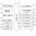
- FIG. 6 is a block diagram showing the input / output relationship of the main controller 50 that centrally configures the control system of the liquid crystal exposure apparatus 10 (see FIG. 1) and performs overall control of each component.
- the main controller 50 includes a workstation (or a microcomputer) and the like, and comprehensively controls each part of the liquid crystal exposure apparatus 10.
- the mask M is loaded onto the mask stage 14 by a mask loader (not shown) under the control of the main controller 50 (see FIG. 6).
- the substrate P is loaded onto the substrate stage device 20 (the substrate carrier 40 and the non-contact holder 32) by a substrate loader (not shown).
- the main controller 50 executes alignment measurement using an alignment detection system (not shown) and focus mapping using an autofocus sensor (surface position measurement system of the substrate P) (not shown). After the focus mapping is completed, a step-and-scan exposure operation is sequentially performed on a plurality of shot areas set on the substrate P.
- FIGS. 7 (a) to 9 (b) an example of the operation of the substrate stage apparatus 20 during the exposure operation will be described with reference to FIGS. 7 (a) to 9 (b).
- the exposure process is described as being performed from the first shot region S1 set on the ⁇ Y side and the + X side of the substrate P as an example.
- some elements of the substrate stage device 20 are omitted in FIGS. 7A to 9B.
- FIGS. 7A and 7B are a plan view and a front view, respectively, of the substrate stage apparatus 20 in a state where the alignment operation and the like are completed and the preparation of the exposure operation for the first shot region S1 is completed.
- an exposure region formed on the substrate P by irradiating illumination light IL from the projection optical system 16 (see FIG. 7B, respectively).
- the end on the + X side of the first shot region S1 is somewhat on the ⁇ X side from IA (however, in the state shown in FIG. 7A, the substrate P is not yet irradiated with the illumination light IL).
- the substrate P is positioned based on the output of the horizontal plane position measurement system 70 (see FIG. 6) so as to be positioned.
- the + Y side of the substrate P held by the substrate carrier 40 The vicinity of the end protrudes from the non-contact holder 32.
- the protruding portion of the substrate P is supported from below by an auxiliary table 34 disposed on the + Y side of the non-contact holder 32.
- the substrate carrier is synchronized with the mask M (see FIG. 1) as shown in FIGS. 8A and 8B.
- 40 and the non-contact holder 32 are driven integrally (synchronously) in the + X direction on the X guide bar 28 based on the output of the horizontal plane position measurement system 70 (see FIG. 6).
- And deceleration) see black arrow in FIG. 8A.
- the substrate carrier 40 and the non-contact holder 32 are driven at a constant speed in the X-axis direction
- the substrate P has illumination light IL (see FIG. 8B, respectively) that has passed through the mask M (see FIG. 1) and the projection optical system 16.
- the substrate carrier 40 is appropriately finely driven in the direction of three degrees of freedom in the horizontal plane with respect to the non-contact holder 32 according to the alignment measurement result, and the non-contact holder 32 is moved according to the result of the focus mapping. It is finely driven appropriately in the tilt direction.
- a pair of head units 72 is used.
- Each Y slider 76 (see FIG. 4) is in a stationary state (however, the head unit 72 does not have to be strictly stationary, and at least a part of the head included in the head unit 72 is a scale plate in the Y-axis direction. 46 may be sufficient).
- the substrate stage device 20 moves to the + Y side of the first shot region S1 as shown in FIGS. 9A and 9B.
- the substrate carrier 40 is a predetermined distance in the ⁇ Y direction with respect to the non-contact holder 32 (a distance approximately half of the width direction dimension of the substrate P), and the position in the horizontal plane. It is driven (Y step drive) based on the output of the measurement system 70 (see FIG. 6) (see the black arrow in FIG. 9A).
- the Y step operation of the substrate carrier 40 the vicinity of the ⁇ Y side end of the substrate P held by the substrate carrier 40 is supported from below by the auxiliary table 34 disposed on the ⁇ Y side of the non-contact holder 32.
- the Y sliders 76 (see FIG. 4 respectively) of each of the pair of head units 72 are used as the substrate carrier. It is driven in the Y-axis direction in synchronism with 40 (however, it is not necessary that the speeds exactly match).
- the substrate carrier 40 and the non-contact holder 32 are driven in the ⁇ X direction in synchronization with the mask M (see FIG. 1), so that the scanning exposure for the second shot region S2 is performed. Is called.
- the Y step operation of the substrate carrier 40 and the constant velocity movement in the X-axis direction of the substrate carrier 40 and the non-contact holder 32 synchronized with the mask M are repeated as appropriate, so that all shots set on the substrate P The scanning exposure operation for the area is sequentially performed.
- the substrate stage apparatus 20 included in the liquid crystal exposure apparatus 10 according to the first embodiment described above, only the outer peripheral edge of the substrate P is held when performing high-precision positioning of the substrate P in the XY plane. Since the frame-shaped substrate carrier 40 is driven in the direction of three degrees of freedom in the horizontal plane, for example, the substrate holder that sucks and holds the entire lower surface of the substrate P is driven in the direction of three degrees of freedom in the horizontal plane to perform high-precision positioning of the substrate P. Compared to the case, since the object to be driven (the substrate carrier 40 in the present embodiment) is lightweight, the position controllability is improved. Further, the driving actuator (in this embodiment, the Y voice coil motor 64 and the X voice coil motor 66) can be reduced in size.
- the position measurement system 70 in the horizontal plane for obtaining the position information of the substrate P in the XY plane includes an encoder system, the influence of air fluctuation can be reduced as compared with, for example, a conventional interferometer system. Accordingly, the positioning accuracy of the substrate P is improved. In addition, since the influence of air fluctuation is small, the partial air conditioning equipment that is essential when using the conventional interferometer system can be omitted, and the cost can be reduced.
- auxiliary plate members 42b are connected to the outer surfaces of the pair of X frames 42x. Yes.
- the plate member 42b is disposed substantially parallel to the XY plane, and the lower surface thereof faces the upper surface of the air levitation unit 36 with a predetermined gap.
- the plurality of air levitation units 36 exert a force (lift) in the + Z direction (upward in the gravitational direction) on the substrate carrier 40A by ejecting gas to the lower surface of the plate member 42b.
- the plate member 42b is always supported by the plurality of air levitation units 36 from below, it is assumed that there is a step (between the non-contact holder 32 and the plurality of air levitation units 36). Even when the height difference in the Z-axis direction is formed, when the substrate carrier 40A moves relative to the non-contact holder 32 in the Y-axis direction, the X frame 42x and the non-contact holder 32 (or air) Contact with the levitation unit 36) can be prevented.
- the reference indicator plate 144 may be attached to the substrate carrier 140 and the mark measurement sensor 132 may be attached to the substrate table 30.
- a plurality of reference marks 146 are formed on the reference indicator plate 144 so as to be separated from each other in the Y-axis direction.
- the reference indicator plate 144 has an upper surface of the Y frame 142y on the ⁇ X side of the substrate carrier 140 so that the Z position of the plurality of reference marks 146 is substantially the same as the Z position of the surface of the substrate P (see FIG. 11). It is fixed via a raising member 148.
- the plurality of mark measurement sensors 132 are attached to a flat plate-like member 134 having a T-shape (see FIG. 12B) in plan view formed by protruding from the ⁇ X side side surface of the substrate table 30. ing. As shown in FIG. 12B, the plurality of mark measurement sensors 132 correspond to the plurality of reference marks 146 (that is, overlap with the plurality of reference marks 146 in the vertical direction), and are mutually in the Y-axis direction. They are spaced apart.
- the second modification for example, optical characteristics (for example, scaling, shift, rotation, etc.) of the projection optical system 16 (see FIG. 1) using a plurality of reference marks 146 and a plurality of corresponding mark measurement sensors 132 are used. Calibration is performed. Since the calibration method is substantially the same as the calibration method disclosed in, for example, Japanese Patent Application Laid-Open No. 2006-330534, description thereof is omitted. In the second modification, since the substrate table 30 mechanically separated from the substrate carrier 140 having the reference mark 146 has the mark measurement sensor 132, wiring or the like is not necessary for the substrate carrier 140 itself. In addition, the substrate carrier 140 can be reduced in weight.
- optical characteristics for example, scaling, shift, rotation, etc.
- the Y frame 142y of the substrate carrier 140 according to the second modified example is formed wider than the first embodiment. Then, as shown in FIG. 12B, the upper surface of the flat plate member 134 and the upper surface of the flat plate member 136 protruding from the side surface on the + X side of the substrate table 30 are respectively provided with a Y axis. Two air bearings 138, for example spaced apart in the direction, are mounted. As shown in FIG.
- the air bearing 138 supports the substrate carrier 140 in a non-contact manner through a predetermined gap by ejecting pressurized gas to the lower surface of the opposing Y frame 142y. Thereby, the bending of the substrate carrier 140 is suppressed.
- the air bearing 138 may be attached to the substrate carrier 140 side so as to face the upper surfaces of the flat members 134 and 136. Further, instead of the air bearing 138, the substrate carrier 140 may be magnetically levitated using, for example, a magnet, or buoyancy may be applied using an actuator such as a voice coil motor.
- the Z of the Y linear actuator 62, the Y voice coil motor 64, and the X voice coil motor 66 is shown.
- the position may be set to be the same as that of the substrate carrier 40A. That is, in the substrate stage apparatus 220, the Y movable element 64b of the Y voice coil motor 64 and the X movable element 66b of the X voice coil motor 66 are fixed to the side surface of the Y frame 42y of the substrate carrier 40A.
- the Y stator 62a of the Y linear actuator 62 for driving the Y stator 62a of the Y voice coil motor 64 and the Y mover 62b to which the X stator 66a of the X voice coil motor 66 is attached in the Y-axis direction. Is mounted on the coarse movement stage 224 via a support 62c so as to be the same as the Z position of the substrate carrier 40.
- the substrate carrier 40A of the third modification is supported from below by a plurality of air levitation units 36, as in the first modification (see FIGS. 10A and 10B). It has a pair of auxiliary plate members 42b. Further, as shown in FIG. 13B, as in the second modified example (see FIGS. 11 to 12B), a flat plate is formed from each of the ⁇ X side and + X side side surfaces of the substrate table 30.
- the members 234 and 236 project in the shape of an air, and air levitation units 238 extending in the Y-axis direction are fixed on the members 234 and 236, respectively.
- the height position of the upper surface of the air levitation unit 238 is set lower than the height position of the upper surface of the air levitation unit 36.
- the Y frame 242y is always supported in a non-contact manner from below by the air floating unit 238 (regardless of the position in the Y-axis direction).
- the substrate carrier 40A is placed on the pair of air levitation units 238. Thereby, the bending of the substrate carrier 40A is suppressed.
- the substrate carrier 40 holding the substrate P moves with a long stroke integrally with the non-contact holder 32 in the scanning direction, and also in the non-scanning direction.
- the substrate stage apparatus 420 of the second embodiment holds the substrate P contrary to the first embodiment, whereas the substrate stage apparatus 420 of the second embodiment separates from the non-contact holder 32 and moves with a long stroke.
- the substrate carrier 440 is different in that it moves in a long stroke integrally with the non-contact holder 32 in the non-scanning direction, and moves in a long stroke separately from the non-contact holder 32 in the scanning direction.
- the substrate stage apparatus 420 according to the second embodiment is generally configured such that the substrate stage apparatus 20 according to the first embodiment is rotated by, for example, 90 ° around the Z axis. Yes.
- the longitudinal direction of the substrate P is substantially parallel to the X axis as in the first embodiment.
- the substrate stage device 420 includes a base frame 422, a coarse movement stage 424, a weight cancellation device 26 (not shown in FIG. 14, refer to FIG. 15A, etc.), a Y guide bar 428 (FIG. 14). (Not shown in FIG. 15A), a substrate table 30 (not shown in FIG. 14, see FIG. 17A), a non-contact holder 32, a pair of auxiliary tables 434, a substrate carrier 440, and the like. Yes.
- the base frame 422, the coarse movement stage 424, the Y guide bar 428, the pair of auxiliary tables 434, and the substrate carrier 440 are respectively the base frame 22, the coarse movement stage 24, the X guide bar 28, and the substrate table in the first embodiment.
- 30 and the non-contact holder 32, the pair of auxiliary tables 34, and the substrate carrier 40 are substantially the same as those in the first embodiment.
- an undercarriage part that is a part of the apparatus main body 418 installed on the floor F via the vibration isolator 18d.
- 418b is made of a single plate-like member, and a Y guide bar 428 is fixed to the upper surface of the lower base 418b.
- the weight canceling device 26 is placed.
- the base frame 422 has a pair of Y beams 422a installed on the floor F via the leg portions 422b.
- a coarse movement stage 424 is placed on the frame 422 so as to be movable with a predetermined long stroke in the Y-axis direction.
- the coarse movement stage 424 has a pair of Y tables 424b that connect the vicinity of the ends of the + Y side and the ⁇ Y side of the pair of Y carriages 424a.
- the Y table 424b has one end of a connection device 26a for pulling the weight cancellation device 26 (see FIG. 15A, etc.) and a connection device for pulling the substrate table 30 (see FIG. 17B, etc.). One end of 30b is connected.
- an X stator 462a is fixed to the pair of Y tables 424b via support columns 462c.
- the X stator 462a and the X mover 462b constitute an X linear actuator 462.
- a Y stator 464a and an X stator 466a are attached to the X mover 462b.
- the substrate table 30 and the non-contact holder 32 are rectangular with the X-axis direction as the longitudinal direction in plan view, as in the first embodiment. It consists of a plate-shaped (or box-shaped) member.
- Each of the pair of auxiliary tables 434 includes a plurality of air levitation units 436 supported from below by arm-shaped support members 436 a protruding from the side surface of the substrate table 30.
- the air levitation unit 436 includes a member extending in the X-axis direction.
- a pair of air levitation units 438 are connected to the substrate table 30 via support members 438a.
- the air levitation unit 438 functions in the same manner as the air levitation unit 238 of the third modified example (see FIGS. 13A and 13B) except that it extends in the X-axis direction. That is, as shown in FIG. 14, the pair of air levitation units 438 support the pair of X frames 442x included in the substrate carrier 440 from below without contact.
- the substrate carrier 440 is formed of a rectangular frame (frame shape) member similar to that of the first embodiment (see FIG. 3 and the like), and a pair X frame 442x and a pair of Y frames 442y.
- the Y frame 42y is attached to the lower surface side of the X frame 42x (see FIG. 3)
- the Y frame 442y is attached to the upper surface side of the X frame 442x.
- the plurality of suction pads 44 are attached to the lower surface of the Y frame 442y.
- the point which the some scale board 46 is attached to each of a pair of X frame 442x is the same as the said 1st Embodiment.
- the Y voice coil motor 464 and the X voice coil motor 466 are provided on the side surfaces of the pair of X frames 442 x together with the Y stator 464 a and the X stator 466 a (see FIG. 16A, respectively).
- the Y mover 464b and the X mover 466b constituting the reference a) are attached. Since the position measurement system of the substrate carrier 440 is the same as that of the first embodiment, description thereof is omitted.
- the main controller 50 positions the substrate P with respect to the exposure area IA in the X-axis direction by driving only the substrate carrier 440 in the X-axis direction. Do. A region of the substrate P that is not supported by the non-contact holder 32 is supported by one of the pair of auxiliary tables 434.
- only the substrate carrier 440 is driven with a long stroke in the X-axis direction with respect to the exposure area IA, so that the substrate P moves over the non-contact holder 32 (a predetermined gap). Pass through).
- the non-contact holder 32 flattenes the substrate P passing through the sky in a non-contact manner.
- the main controller 50 determines the Y-axis direction of the substrate P relative to the projection optical system 16 (that is, the exposure area IA (see FIG. 19A)).
- the coarse movement stage 424 and the non-contact holder 32 are driven with a predetermined long stroke in the Y-axis direction, and the substrate carrier 440 is moved integrally with the coarse movement stage 424 in the Y-axis direction.
- the substrate carrier 440 since only the substrate carrier 440 is driven in the scanning direction at the time of scanning exposure, it is necessary to drive the non-contact holder 32 and the pair of auxiliary tables 34 together in the scanning direction. Compared to the first embodiment (see FIG. 8A and the like), the occurrence of vibration can be suppressed, and a highly accurate exposure operation can be performed. Further, since the weight canceling device 26 moves only during the Y step operation, the longitudinal dimension of the Y guide bar 428 is shorter than the X guide bar 28 of the first embodiment. Further, since the weight cancellation device 26 is in a stationary state during the exposure operation, the flatness of the guide surface of the Y guide bar 428 which is a surface plate for the weight cancellation device 26 is higher than that of the first embodiment. Rough and good.
- the configuration described in the second embodiment is an example and can be modified as appropriate.
- the pair of auxiliary tables 534 includes the substrate table 30 (FIG. 24 (a)) may be physically separated.
- the fourth modification will be described only with respect to differences from the second embodiment, and common elements are denoted by the same reference numerals as those of the second embodiment, and description thereof is omitted.
- Y guide bars 528 are fixed on the gantry 418b at predetermined intervals in the X-axis direction.
- the Y guide bar 528 is formed with the same size and shape as the Y guide bar 428 (see FIG. 15A and the like) of the second embodiment, but in the fourth modification example, the weight cancellation device 26 is placed on the Y guide bar 528 via the mechanical linear guide device 26d, the flatness of the upper surface of the Y guide bar 528 is the same as that of the Y guide bar 428 according to the second embodiment. Compared to rough.
- a Z actuator 526 is placed via a Y linear guide device 26d.
- a pair of plate-like members 524a project in the + Y and ⁇ Y directions and are connected to the pair of Y tables 424b included in the coarse movement stage 524, respectively.
- One end of a connection device 26a for pulling the Z actuator 526 is connected to the plate-like member 524a. That is, in the fourth modification, for example, two Z actuators 526 (see FIG. 22B, respectively) are moved by the coarse movement stage 524 in the same manner as the weight cancellation device 26 (integrated with the weight cancellation device 26). Towed.
- each of the pair of auxiliary tables 534 has a plurality of air levitation units 436 (for example, four in FIG. 24A).
- the plurality of air levitation units 436 support a portion of the substrate P that is not supported by the non-contact holder 32 from below, as in the second embodiment.
- the auxiliary table 534 has a pair of air levitation units 538.
- the plurality of air levitation units 436 and the pair of air levitation units 538 are integrally mounted on the base member 536a.
- the + X side auxiliary table 534 is supported from below by the + X side Z actuator 526 (see FIG.
- the ⁇ X side auxiliary table 534 is the above-described ⁇ X side Z actuator 526 ( It is supported from below (see FIG. 22B, etc.) (see FIG. 26B).
- a pair of air levitation units 538 are also fixed to the substrate table 30 via support members 538a.
- the air levitation unit 438 of the second embodiment is formed with a length that can cover the entire movement range in the X-axis direction of the substrate carrier 440 (see FIG. 14 respectively) (about three times the substrate P).
- the air levitation unit 538 of the present modification is formed with a length that is approximately the same as that of the other air levitation unit 436 (same as the substrate P).
- the X frame 442x (see FIG. 21) of the substrate carrier 540 includes a plurality of air levitation units 538 (air levitation units 538 included in the auxiliary table 534, and The substrate table 30 is appropriately supported from below by an air levitation unit 538).
- the Y frame 442y is X via a spacer 442a (not shown in FIG. 25A hidden behind the Y frame 442y). It is fixed on the frame 442x.
- the pair of suction pads 44 on the ⁇ X side are attached to the lower surface of the Y frame 442y on the ⁇ X side, whereas the pair of suction pads 44 on the + X side protrude from the inner surface of the X frame 442x. Is formed.
- the substrate carrier 540 of the present modified example the substrate P is moved in the + X direction from the state shown in FIG. 25A, as shown in FIG. , The substrate P can be unloaded from the substrate carrier 40. Further, the substrate P can be carried into the substrate carrier 40 by moving the substrate P in the ⁇ X direction.
- a reference index plate in which a plurality of reference marks 146 are formed. 144 is fixed via a raising member 148.
- a plurality of mark measurement sensors 532 are attached to the lower surface of the ⁇ X side Y frame 442 y corresponding to the plurality of reference marks 146. That is, in the second modified example, the reference index plate 144 and the mark measurement sensor 132 are provided separately (see FIG. 11), whereas in the present modified example, the reference index plate 144 and the mark measurement sensor are provided. 532 and the substrate carrier 540 are integrally provided. Since the calibration using the reference index plate 144 is the same as that of the second modified example, the description thereof is omitted.
- FIGS. 26A and 26B show the substrate stage device 520 during the unloading operation of the substrate P.
- the substrate P is carried out in a state where the substrate carrier 540 is supported by the non-contact holder 32 in the center of the movement range in the X-axis direction, that is, almost the entire substrate P. After the suction and holding by the substrate carrier 540 is released, the substrate P slides in the + X direction with respect to the substrate carrier 540 by an unillustrated unloader. As a result, the substrate P is transferred (transferred) from the non-contact holder 32 onto the plurality of air levitation units 438 included in the + X side auxiliary table 534.
- the carry-out device for sliding the substrate P in the X-axis direction may be provided outside the substrate stage device 520 (including an external device of the liquid crystal exposure apparatus), or the substrate stage device 520 itself has. May be.
- the pair of auxiliary tables 534 and the substrate table 30 (and the non-contact holder 32) are physically separated, so that the drive The Z tilt position controllability of the substrate P is improved by reducing the weight of the object.
- the Z position of each of the pair of auxiliary tables 534 can be controlled independently, for example, when the substrate P moves (loads) from the non-contact holder 32 onto the air floating unit 436 of the auxiliary table 534. By slightly lowering the Z position of the auxiliary table 534, contact between the end of the substrate P and the air floating unit 436 can be avoided.
- the substrate P can be carried out (and carried in) by sliding the substrate P, the substrate on the substrate carrier 540 can be easily exchanged even when the space above the substrate stage device 520 is narrow. Can do.
- the substrate carrier 40 and the like are, for example, four frame members (in the first embodiment, a pair of X frames 42x and a pair of substrates) along the outer peripheral edge (four sides) of the substrate P.
- the Y frame 42y is formed into a rectangular frame shape.
- the substrate carrier 40 is not limited to this as long as the substrate P can be reliably sucked and held, and the substrate carrier 40 is, for example, one of the outer peripheral edges of the substrate P. You may be comprised by the frame member along a part.
- the substrate carrier may be formed in a U shape in plan view by, for example, three frame members along the three sides of the substrate P, or on two adjacent sides of the substrate P.
- two frame members may be formed on the L shape in plan view.
- the substrate carrier may be formed by only one frame member along one side of the substrate P, for example.
- the substrate carrier may be constituted by a plurality of members that hold different portions of the substrate P and whose positions are controlled independently of each other.
- the Z tilt position measurement system 58 is attached to a target 58b fixed to the casing of the weight cancellation device 26 by a laser displacement meter 58a provided on the lower surface of the substrate table 30.
- the measurement light is irradiated and the reflected light is received to obtain the displacement amount information of the substrate table 30 in the Z-axis direction.
- the present invention is not limited to this.
- a Z sensor head 78z is arranged in the head unit 72 together with the X head 78x and the Y head 78y.
- a laser displacement meter is used as the Z sensor head 78z.
- a reflective surface is formed by mirror finishing in a region where a scale facing the X head 78x and the Y head 78y is not disposed.
- the Z sensor head 78z irradiates the measurement surface with the measurement beam, and receives the reflection beam from the reflection surface, whereby displacement information in the Z-axis direction of the substrate carriers 40 and 440 at the measurement beam irradiation point Ask for.
- the type of the Z head 78z is such that the displacement in the Z-axis direction of the substrate carriers 40 and 440 (more specifically, the X frame 42x) with reference to the apparatus main body 18 (see FIG. 1) can be achieved with a desired accuracy (resolution). And if it can measure in non-contact, it will not specifically limit.
- the position information in the XY plane of each of the substrate P and the Y slider 76 is obtained by the X encoder head 78x and the Y encoder head 78y.
- a two-dimensional encoder head capable of measuring displacement information in the Z-axis direction. (XZ encoder head or YZ encoder head) may be used to obtain the Z tilt displacement information of each of the substrate P and Y slider 76 together with the positional information of the substrate P and Y slider 76 in the XY plane. .
- the scale plate 46 is as long as the X frame 42x. It is preferable that the two-dimensional encoder heads are arranged at a predetermined interval in the X-axis direction, for example, by three long scale plates.
- the plurality of scale plates 46 are arranged at predetermined intervals in the X-axis direction.
- the present invention is not limited to this, and for example, the substrate carrier 40 or the like is formed with a length similar to the length in the X-axis direction.
- a single long scale plate may be used.
- each head unit 72 has only one X head 78x and one Y head 78y.
- the scale plate 82 When a plurality of scale plates 46 are provided, the lengths of the scale plates 46 may be different from each other.
- the head unit 72 controls the position of the substrate P across different scale plates 46 during the scanning exposure operation. Can be avoided. Further, the length may be different between the scale arranged on one side of the projection optical system 16 and the scale arranged on the other side (for example, in the case of four chamfering and six chamfering).
- the encoder system although position measurement in horizontal surfaces, such as the board
- a bar mirror may be attached, and the position of the substrate carrier 40 or the like may be measured by an interferometer system using the bar mirror.
- the substrate carrier 40 and the like have the scale plate 46 (diffraction grating) and the head unit 72 has the measurement head.
- the present invention is not limited to this, and the substrate carrier 40 and the like. May have a measurement head, and a scale plate that moves in synchronization with the measurement head may be attached to the apparatus main body 18 (arrangement opposite to that in the above embodiments).
- the present invention is not limited to this.
- the air levitation unit 36 when the substrate P moves in the X-axis direction, the air levitation unit 36 having a length that can prevent the substrate P from being bent (covers the moving range of the substrate P) is provided in the non-contact holder 32.
- the air levitation unit 36 may also be fixedly disposed without moving in the X-axis direction.
- the air levitation unit 36 having a length that can prevent the substrate P from being bent (covers the movement range of the substrate P) is provided in the non-contact holder 32.
- the air levitation unit 36 may also be fixedly disposed without moving in the Y-axis direction.
- the non-contact holder 32 supports the substrate P in a non-contact manner.
- the non-contact holder 32 is not limited to this as long as the relative movement in the direction parallel to the horizontal plane between the substrate P and the non-contact holder 32 is not hindered.
- it may be supported in a contact state via a rolling element such as a ball.
- the wavelength of the light source used in the illumination system 12 and the illumination light IL emitted from the light source is not particularly limited.
- ultraviolet light such as ArF excimer laser light (wavelength 193 nm), KrF excimer laser light (wavelength 248 nm), or the like.
- Light or vacuum ultraviolet light such as F2 laser light (wavelength 157 nm) may be used.
- the projection optical system 16 is an equal magnification system.
- the present invention is not limited to this, and a reduction system or an enlargement system may be used.
- the use of the exposure apparatus is not limited to an exposure apparatus for liquid crystal that transfers a liquid crystal display element pattern onto a square glass plate.
- an exposure apparatus for manufacturing an organic EL (Electro-Luminescence) panel, a semiconductor The present invention can be widely applied to an exposure apparatus for manufacturing, an exposure apparatus for manufacturing a thin film magnetic head, a micromachine, a DNA chip, and the like.
- an exposure apparatus for manufacturing a thin film magnetic head a micromachine, a DNA chip, and the like.
- the present invention can also be applied to an exposure apparatus that transfers a circuit pattern.
- the object to be exposed is not limited to the glass plate, but may be another object such as a wafer, a ceramic substrate, a film member, or a mask blank.
- the thickness of the substrate is not particularly limited, and includes, for example, a film-like (flexible sheet-like member).
- the exposure apparatus of the present embodiment is particularly effective when a substrate having a side length or diagonal length of 500 mm or more is an exposure target. Further, when the substrate to be exposed is a flexible sheet, the sheet may be formed in a roll shape.
- the step of designing the function and performance of the device the step of producing a mask (or reticle) based on this design step, and the step of producing a glass substrate (or wafer)
- the above-described exposure method is executed using the exposure apparatus of the above embodiment, and a device pattern is formed on the glass substrate. Therefore, a highly integrated device can be manufactured with high productivity. .
- the mobile device of the present invention is suitable for moving an object.
- the exposure apparatus of the present invention is suitable for forming a predetermined pattern on an object.
- the manufacturing method of the flat panel display of this invention is suitable for production of a flat panel display.
- the device manufacturing method of the present invention is suitable for the production of micro devices.
- SYMBOLS 10 Liquid crystal exposure apparatus, 20 ... Substrate stage apparatus, 22 ... Base frame, 24 ... Coarse movement stage, 26 ... Weight cancellation apparatus, 28 ... X guide bar, 32 ... Non-contact holder, 34 ... Auxiliary table, 40 ... Substrate carrier , P: substrate.
Landscapes
- Physics & Mathematics (AREA)
- General Physics & Mathematics (AREA)
- Engineering & Computer Science (AREA)
- Sustainable Development (AREA)
- Life Sciences & Earth Sciences (AREA)
- Environmental & Geological Engineering (AREA)
- Health & Medical Sciences (AREA)
- Epidemiology (AREA)
- Public Health (AREA)
- Multimedia (AREA)
- Exposure And Positioning Against Photoresist Photosensitive Materials (AREA)
- Container, Conveyance, Adherence, Positioning, Of Wafer (AREA)
- Liquid Crystal (AREA)
- Devices For Indicating Variable Information By Combining Individual Elements (AREA)
Abstract
Description
以下、第1の実施形態について、図1~図9(b)を用いて説明する。
次に第2の実施形態に係る液晶露光装置について、図14~図20(b)を用いて説明する。第2の実施形態に係る液晶露光装置の構成は、基板ステージ装置420の構成が異なる点を除き、上記第1の実施形態と同じであるので、以下、相違点についてのみ説明し、上記第1の実施形態と同じ構成及び機能を有する要素については、上記第1の実施形態と同じ符号を付してその説明を省略する。
Claims (26)
- 光学系を介して照明光を物体に照射して、前記照明光に対して前記物体を相対駆動して前記物体の複数の領域をそれぞれ走査露光する露光装置であって、
前記複数の領域のうち第1領域と第1方向に関して前記第1領域と並んで設けられた第2領域の少なくとも一部の領域とを非接触支持する第1支持部と、
前記第1方向と交差する第2方向に関して前記第1支持部と重ならない位置で前記第1支持部により非接触支持された前記物体を保持する保持部と、
前記第2方向に関して前記第1支持部と離間して配置され、前記第2領域の他部の領域が前記第1支持部に支持されるように、前記物体を保持する前記保持部を前記第1支持部に対して前記第1方向へ相対駆動させる第1駆動部と、を備える露光装置。 - 前記第1支持部は、前記物体のほぼ全面を支持可能な大きさを有し、
前記物体のほぼ全面が前記第1支持部により非接触支持される第1状態と、前記第1駆動部の駆動により前記物体の一部が前記第1支持部から外れ前記物体の他部が前記第1支持部により非接触支持される第2状態とを切り替え可能に前記第1駆動部を制御する制御部を、さらに備える請求項1に記載の露光装置。 - 前記制御部は、前記走査露光時と前記走査露光時以外とで前記第1状態と前記第2状態とを切り替える請求項2に記載の露光装置。
- 前記物体が有する複数のマークを検出するマーク検出動作を行うマーク検出部をさらに備え、
前記制御部は、前記マーク検出動作時に前記第1状態となるように前記第1駆動部を制御する請求項3に記載の露光装置。 - 前記支持部を前記第2方向へ駆動する第2駆動部をさらに備え、
前記第1及び2駆動部は、前記走査露光時に、前記保持部と前記第1支持部とをそれぞれ前記第2方向へ駆動させる請求項1~4のいずれか一項に記載の露光装置。 - 前記第1支持部を前記第2方向へ駆動する第2駆動部をさらに備え、
前記第2駆動部は、前記走査露光時に、前記保持部を前記第1方向へ駆動させ、
前記第1及び前記第2駆動部は、前記保持部と前記第1支持部とをそれぞれ前記第2駆動部へ駆動させ、前記走査露光を行う前記物体内の領域を変更する前記請求項1~5のいずれか一項に記載の露光装置。 - 照明光を物体に照射して、前記照明光に対して前記物体を第1方向に相対移動して前記物体の複数の領域をそれぞれ走査露光する露光装置であって、
前記複数の領域のうち少なくとも第1領域を非接触支持する第1支持部と、
前記支持部により非接触支持された前記物体を保持する保持部と、
前記保持部を、前記第1方向と前記第1方向に交差する第2方向との一方の方向に関して、前記第1領域の一部が前記支持部を外れるように前記支持部に対して相対駆動する第2駆動系と、
前記支持部を他方の方向へ駆動する第2駆動系と、を備える露光装置。 - 光学系を介して照明光を物体に照射して、前記照明光に対して前記物体を駆動して前記物体を走査露光する露光装置であって、
前記物体のほぼ全面を非接触支持する第1支持部と、
前記第1支持部により非接触支持された前記物体を保持する保持部と、
前記保持部を前記第1支持部に対して相対駆動させる駆動部と、を備え、
前記駆動部は、前記第1支持部にほぼ全面が非接触支持された前記物体を保持する前記保持部を、前記物体の一部が前記第1支持部から外れるように、前記物体内の前記照明光が照射される領域に対して相対駆動する露光装置。 - 前記物体のうち、前記第1支持部に支持された領域以外の領域を支持する第2支持部をさらに備える請求項1~8のいずれか一項に記載の露光装置。
- 前記保持部は、一対の第1部材と前記第1部材の上に設けられた一対の第2部材とにより構成され、
前記第1部材は、上下方向に関して前記支持部よりも低い位置に設けられる1~9のいずれか一項に記載の露光装置。 - 前記第1及び第2方向に関する前記保持部の位置情報を求めるエンコーダシステムを更に備え、
前記エンコーダシステムを構成するヘッド及びスケールの少なくとも一方は、前記保持部に設けられる請求項10に記載の露光装置。 - 前記ヘッド及びスケールの一方は、前記第2部材に設けられる請求項11に記載の露光装置。
- 前記保持部の位置情報を求める際の基準となる基準部材をさらに備え、
前記基準部材は、前記第1部材に設けられる請求項10~12のいずれか一項に記載の露光装置。 - 前記第1支持部は、前記物体の下面に対して空気を供給する供給孔を有する請求項1~13のいずれか一項に記載の露光装置。
- 前記第1支持部は、前記物体の下面に介在する空気を吸引する吸引孔を有する請求項14に記載の露光装置。
- 前記物体は、フラットパネルディスプレイに用いられる基板である請求項1~15のいずれか一項に記載の露光装置。
- 前記基板は、少なくとも一辺の長さ又は対角長が500mm以上である請求項16に記載の露光装置。
- 請求項1~17のいずれか一項に記載の露光装置を用いて前記物体を露光することと、
露光された前記物体を現像することと、を含むフラットパネルディスプレイの製造方法。 - 請求項1~17のいずれか一項に記載の露光装置を用いて前記物体を露光することと、
露光された前記物体を現像することと、を含むデバイス製造方法。 - 光学系を介して照明光を物体に照射して、前記照明光に対して前記物体を相対駆動して前記物体の複数の領域をそれぞれ走査露光する露光方法であって、
前記複数の領域のうち第1領域と第1方向に関して前記第1領域と並んで設けられた第2領域の少なくとも一部の領域とを第1支持部により非接触支持することと、
前記第1方向と交差する第2方向に関して前記第1支持部と重ならない位置で前記第1支持部により非接触支持された前記物体を保持部により保持することと、
前記第2方向に関して前記第1支持部と離間して配置された第1駆動部により、前記第2領域の他部の領域が前記第1支持部に支持されるように、前記物体を保持する前記保持部を前記第1支持部に対して前記第1方向へ相対駆動することと、を含む露光方法。 - 前記第1支持部は、前記物体のほぼ全面を支持可能な大きさを有し、
前記物体のほぼ全面が前記第1支持部により非接触支持される第1状態と、前記第1駆動部の駆動により前記物体の一部が前記第1支持部から外れ前記物体の他部が前記第1支持部により非接触支持される第2状態とを切り替え可能に前記第1駆動部を制御することを、さらに含む請求項20に記載の露光方法。 - 前記制御することでは、前記走査露光時と前記走査露光時以外とで前記第1状態と前記第2状態とを切り替える請求項21に記載の露光方法。
- 前記制御することでは、前記物体が有する複数のマークを検出するマーク検出動作を行うマーク検出部による前記マーク検出動作時に前記第1状態となるように前記第1駆動部を制御する請求項22に記載の露光方法。
- 前記第1駆動部と前記支持部を前記第2方向へ駆動する第2駆動部とにより、前記走査露光時に、前記保持部と前記第1支持部とをそれぞれ前記第2方向へ駆動することを更に含む請求項20~23のいずれか一項に記載の露光方法。
- 照明光を物体に照射して、前記照明光に対して前記物体を第1方向に相対移動して前記物体の複数の領域をそれぞれ走査露光する露光方法であって、
前記複数の領域のうち少なくとも第1領域を第1支持部により非接触支持することと、
前記支持部により非接触支持された前記物体を保持部により保持することと、
前記保持部を、前記第1方向と前記第1方向に交差する第2方向との一方の方向に関して、前記第1領域の一部が前記支持部を外れるように前記支持部に対して相対駆動することと、
前記支持部を他方の方向へ駆動することと、を含む露光方法。 - 光学系を介して照明光を物体に照射して、前記照明光に対して前記物体を駆動して前記物体を走査露光する露光方法であって、
前記物体のほぼ全面を第1支持部により非接触支持することと、
前記第1支持部により非接触支持された前記物体を保持部により保持することと、
前記保持部を前記第1支持部に対して相対駆動することと、を含み、
前記相対駆動することでは、前記第1支持部にほぼ全面が非接触支持された前記物体を保持する前記保持部を、前記物体の一部が前記第1支持部から外れるように、前記物体内の前記照明光が照射される領域に対して相対駆動する露光方法。
Priority Applications (6)
| Application Number | Priority Date | Filing Date | Title |
|---|---|---|---|
| JP2017543569A JP6885336B2 (ja) | 2015-09-30 | 2016-09-29 | 露光装置、露光方法、フラットパネルディスプレイの製造方法、及びデバイス製造方法 |
| CN202010832457.4A CN111965948B (zh) | 2015-09-30 | 2016-09-29 | 曝光装置、曝光方法、平面显示器的制造方法、及元件制造方法 |
| CN201680057222.4A CN108139680B (zh) | 2015-09-30 | 2016-09-29 | 曝光装置、曝光方法、平面显示器的制造方法、及元件制造方法 |
| US15/763,475 US10802407B2 (en) | 2015-09-30 | 2016-09-29 | Exposure apparatus, exposure method, manufacturing method of flat-panel display, and device manufacturing method |
| KR1020187011649A KR102676391B1 (ko) | 2015-09-30 | 2016-09-29 | 노광 장치, 노광 방법, 플랫 패널 디스플레이의 제조 방법, 및 디바이스 제조 방법 |
| US17/066,834 US20210026253A1 (en) | 2015-09-30 | 2020-10-09 | Exposure apparatus, exposure method, manufacturing method of flat-panel display, and device manufacturing method |
Applications Claiming Priority (2)
| Application Number | Priority Date | Filing Date | Title |
|---|---|---|---|
| JP2015192794 | 2015-09-30 | ||
| JP2015-192794 | 2015-09-30 |
Related Child Applications (2)
| Application Number | Title | Priority Date | Filing Date |
|---|---|---|---|
| US15/763,475 A-371-Of-International US10802407B2 (en) | 2015-09-30 | 2016-09-29 | Exposure apparatus, exposure method, manufacturing method of flat-panel display, and device manufacturing method |
| US17/066,834 Division US20210026253A1 (en) | 2015-09-30 | 2020-10-09 | Exposure apparatus, exposure method, manufacturing method of flat-panel display, and device manufacturing method |
Publications (1)
| Publication Number | Publication Date |
|---|---|
| WO2017057590A1 true WO2017057590A1 (ja) | 2017-04-06 |
Family
ID=58427545
Family Applications (1)
| Application Number | Title | Priority Date | Filing Date |
|---|---|---|---|
| PCT/JP2016/078851 Ceased WO2017057590A1 (ja) | 2015-09-30 | 2016-09-29 | 露光装置、露光方法、フラットパネルディスプレイの製造方法、及びデバイス製造方法 |
Country Status (6)
| Country | Link |
|---|---|
| US (2) | US10802407B2 (ja) |
| JP (3) | JP6885336B2 (ja) |
| KR (1) | KR102676391B1 (ja) |
| CN (2) | CN111965948B (ja) |
| TW (3) | TW202324000A (ja) |
| WO (1) | WO2017057590A1 (ja) |
Cited By (2)
| Publication number | Priority date | Publication date | Assignee | Title |
|---|---|---|---|---|
| CN109870881A (zh) * | 2019-03-20 | 2019-06-11 | 哈尔滨工业大学 | 宏微组合式长行程精密运动平台 |
| JP7511144B2 (ja) | 2020-08-25 | 2024-07-05 | パナソニックIpマネジメント株式会社 | 基板保持装置及び基板保持方法 |
Families Citing this family (8)
| Publication number | Priority date | Publication date | Assignee | Title |
|---|---|---|---|---|
| TWI735438B (zh) * | 2015-03-30 | 2021-08-11 | 日商尼康股份有限公司 | 物體搬運裝置、曝光裝置、平板顯示器的製造方法、元件製造方法、物體搬運方法以及曝光方法 |
| KR102318643B1 (ko) * | 2016-09-30 | 2021-10-27 | 가부시키가이샤 니콘 | 이동체 장치, 이동 방법, 노광 장치, 노광 방법, 플랫 패널 디스플레이의 제조 방법, 그리고 디바이스 제조 방법 |
| JP6735693B2 (ja) * | 2017-02-27 | 2020-08-05 | 株式会社日立ハイテク | ステージ装置、及び荷電粒子線装置 |
| WO2019188274A1 (ja) * | 2018-03-30 | 2019-10-03 | 株式会社ニコン | 保持装置、露光装置、フラットパネルディスプレイの製造方法、デバイス製造方法、及び保持方法 |
| EP3667696A1 (en) * | 2018-12-14 | 2020-06-17 | ASML Netherlands B.V. | Stage apparatus suitable for electron beam inspection apparatus |
| CN109976105A (zh) * | 2019-04-25 | 2019-07-05 | 中山新诺科技股份有限公司 | 曝光机、线路板的支撑机构及支撑方法 |
| JP7756535B2 (ja) * | 2021-10-06 | 2025-10-20 | キヤノン株式会社 | 位置決め装置、リソグラフィ装置、および物品製造方法 |
| JP7624374B2 (ja) * | 2021-11-08 | 2025-01-30 | 株式会社日立ハイテク | ステージ装置及びステージ装置を備える荷電粒子線装置 |
Citations (7)
| Publication number | Priority date | Publication date | Assignee | Title |
|---|---|---|---|---|
| JP2007072267A (ja) * | 2005-09-08 | 2007-03-22 | Sumitomo Chemical Co Ltd | 露光装置 |
| JP2011044713A (ja) * | 2009-08-20 | 2011-03-03 | Nikon Corp | 物体処理装置、露光装置及び露光方法、並びにデバイス製造方法 |
| JP2012060118A (ja) * | 2010-09-07 | 2012-03-22 | Nikon Corp | 移動体装置、物体処理装置、露光装置、フラットパネルディスプレイの製造方法、及びデバイス製造方法 |
| JP2013054144A (ja) * | 2011-09-02 | 2013-03-21 | Nikon Corp | 位置合わせ方法、露光方法、デバイス製造方法、及びフラットパネルディスプレイの製造方法 |
| JP2013179223A (ja) * | 2012-02-29 | 2013-09-09 | Nsk Technology Co Ltd | 分割逐次近接露光装置及び分割逐次近接露光方法 |
| JP2013538434A (ja) * | 2010-09-07 | 2013-10-10 | 株式会社ニコン | 露光装置、移動体装置、フラットパネルディスプレイの製造方法、及びデバイス製造方法 |
| JP2014038224A (ja) * | 2012-08-17 | 2014-02-27 | Nikon Corp | 搬送装置、露光装置及び露光方法、並びにフラットパネルディスプレイの製造方法及びデバイス製造方法 |
Family Cites Families (14)
| Publication number | Priority date | Publication date | Assignee | Title |
|---|---|---|---|---|
| US5729331A (en) | 1993-06-30 | 1998-03-17 | Nikon Corporation | Exposure apparatus, optical projection apparatus and a method for adjusting the optical projection apparatus |
| JP2001215718A (ja) | 1999-11-26 | 2001-08-10 | Nikon Corp | 露光装置及び露光方法 |
| JP4745556B2 (ja) * | 2001-08-20 | 2011-08-10 | キヤノン株式会社 | 位置決め装置、露光装置、及びデバイス製造方法 |
| TWI408506B (zh) | 2005-03-29 | 2013-09-11 | 尼康股份有限公司 | 曝光裝置、曝光裝置的製造方法以及微元件的製造方法 |
| JP2006330534A (ja) | 2005-05-30 | 2006-12-07 | Nikon Corp | 基準指標板、基準指標板の調整方法、露光装置及びマイクロデバイスの製造方法 |
| TWI596444B (zh) | 2006-08-31 | 2017-08-21 | 尼康股份有限公司 | Exposure method and device, and device manufacturing method |
| KR101547784B1 (ko) | 2007-03-05 | 2015-08-26 | 가부시키가이샤 니콘 | 이동체 장치, 패턴 형성 장치 및 패턴 형성 방법, 디바이스 제조 방법, 이동체 장치의 제조 방법, 및 이동체 구동 방법 |
| KR101431146B1 (ko) * | 2008-05-09 | 2014-08-18 | 주식회사 디엠에스 | 약액도포장치 |
| TW201100975A (en) | 2009-04-21 | 2011-01-01 | Nikon Corp | Moving-object apparatus, exposure apparatus, exposure method, and device manufacturing method |
| US20110053092A1 (en) | 2009-08-20 | 2011-03-03 | Nikon Corporation | Object processing apparatus, exposure apparatus and exposure method, and device manufacturing method |
| US8598538B2 (en) | 2010-09-07 | 2013-12-03 | Nikon Corporation | Movable body apparatus, object processing device, exposure apparatus, flat-panel display manufacturing method, and device manufacturing method |
| US8593613B2 (en) * | 2011-09-13 | 2013-11-26 | Shenzhen China Star Optoelectronics Technology Co., Ltd. | LCD exposure stage device and exposure system |
| JP6102230B2 (ja) * | 2012-12-07 | 2017-03-29 | 株式会社ニコン | 露光装置及び露光方法、並びにデバイス製造方法 |
| CN103777478B (zh) * | 2014-02-20 | 2015-12-30 | 江阴长电先进封装有限公司 | 一种非接触式光刻机的晶圆校准水平装置及其应用 |
-
2016
- 2016-09-29 KR KR1020187011649A patent/KR102676391B1/ko active Active
- 2016-09-29 WO PCT/JP2016/078851 patent/WO2017057590A1/ja not_active Ceased
- 2016-09-29 US US15/763,475 patent/US10802407B2/en active Active
- 2016-09-29 JP JP2017543569A patent/JP6885336B2/ja active Active
- 2016-09-29 CN CN202010832457.4A patent/CN111965948B/zh active Active
- 2016-09-29 CN CN201680057222.4A patent/CN108139680B/zh active Active
- 2016-09-30 TW TW112106139A patent/TW202324000A/zh unknown
- 2016-09-30 TW TW105131979A patent/TWI729008B/zh active
- 2016-09-30 TW TW110115789A patent/TWI797605B/zh active
-
2020
- 2020-10-09 US US17/066,834 patent/US20210026253A1/en not_active Abandoned
-
2021
- 2021-05-11 JP JP2021080313A patent/JP2021140172A/ja active Pending
-
2022
- 2022-06-29 JP JP2022104267A patent/JP7384242B2/ja active Active
Patent Citations (7)
| Publication number | Priority date | Publication date | Assignee | Title |
|---|---|---|---|---|
| JP2007072267A (ja) * | 2005-09-08 | 2007-03-22 | Sumitomo Chemical Co Ltd | 露光装置 |
| JP2011044713A (ja) * | 2009-08-20 | 2011-03-03 | Nikon Corp | 物体処理装置、露光装置及び露光方法、並びにデバイス製造方法 |
| JP2012060118A (ja) * | 2010-09-07 | 2012-03-22 | Nikon Corp | 移動体装置、物体処理装置、露光装置、フラットパネルディスプレイの製造方法、及びデバイス製造方法 |
| JP2013538434A (ja) * | 2010-09-07 | 2013-10-10 | 株式会社ニコン | 露光装置、移動体装置、フラットパネルディスプレイの製造方法、及びデバイス製造方法 |
| JP2013054144A (ja) * | 2011-09-02 | 2013-03-21 | Nikon Corp | 位置合わせ方法、露光方法、デバイス製造方法、及びフラットパネルディスプレイの製造方法 |
| JP2013179223A (ja) * | 2012-02-29 | 2013-09-09 | Nsk Technology Co Ltd | 分割逐次近接露光装置及び分割逐次近接露光方法 |
| JP2014038224A (ja) * | 2012-08-17 | 2014-02-27 | Nikon Corp | 搬送装置、露光装置及び露光方法、並びにフラットパネルディスプレイの製造方法及びデバイス製造方法 |
Cited By (2)
| Publication number | Priority date | Publication date | Assignee | Title |
|---|---|---|---|---|
| CN109870881A (zh) * | 2019-03-20 | 2019-06-11 | 哈尔滨工业大学 | 宏微组合式长行程精密运动平台 |
| JP7511144B2 (ja) | 2020-08-25 | 2024-07-05 | パナソニックIpマネジメント株式会社 | 基板保持装置及び基板保持方法 |
Also Published As
| Publication number | Publication date |
|---|---|
| JP7384242B2 (ja) | 2023-11-21 |
| TWI797605B (zh) | 2023-04-01 |
| JP2022133345A (ja) | 2022-09-13 |
| TW202134802A (zh) | 2021-09-16 |
| JPWO2017057590A1 (ja) | 2018-07-19 |
| JP2021140172A (ja) | 2021-09-16 |
| KR20180058798A (ko) | 2018-06-01 |
| KR102676391B1 (ko) | 2024-06-18 |
| US20210026253A1 (en) | 2021-01-28 |
| CN108139680B (zh) | 2021-12-07 |
| TW201723675A (zh) | 2017-07-01 |
| TW202324000A (zh) | 2023-06-16 |
| CN108139680A (zh) | 2018-06-08 |
| JP6885336B2 (ja) | 2021-06-16 |
| US10802407B2 (en) | 2020-10-13 |
| TWI729008B (zh) | 2021-06-01 |
| US20190049856A1 (en) | 2019-02-14 |
| CN111965948B (zh) | 2023-06-27 |
| CN111965948A (zh) | 2020-11-20 |
Similar Documents
| Publication | Publication Date | Title |
|---|---|---|
| JP7384242B2 (ja) | 露光装置、露光方法、フラットパネルディスプレイの製造方法、及びデバイス製造方法 | |
| TWI789689B (zh) | 曝光裝置、平面顯示器之製造方法、及元件製造方法 | |
| US10935894B2 (en) | Movable body apparatus, exposure apparatus, manufacturing method of flat-panel display and device manufacturing method, and movement method of object | |
| CN113433802B (zh) | 移动体装置、移动方法、曝光装置、曝光方法、平板显示器的制造方法、以及元件制造方法 | |
| CN108139685A (zh) | 曝光装置、平面显示器的制造方法、组件制造方法、及曝光方法 | |
| WO2017057465A1 (ja) | 移動体装置、露光装置、フラットパネルディスプレイの製造方法、及びデバイス製造方法、並びに計測方法 | |
| CN108139679B (zh) | 曝光装置、平面显示器的制造方法、组件制造方法、及曝光方法 | |
| HK1249195A1 (en) | Exposure device, exposure method, method for manufacturing flat panel display, and method for manufacturing device | |
| HK1248830A1 (en) | Exposure device, method for manufacturing flat panel display, method for manufacturing device, and exposure method |
Legal Events
| Date | Code | Title | Description |
|---|---|---|---|
| 121 | Ep: the epo has been informed by wipo that ep was designated in this application |
Ref document number: 16851761 Country of ref document: EP Kind code of ref document: A1 |
|
| ENP | Entry into the national phase |
Ref document number: 2017543569 Country of ref document: JP Kind code of ref document: A |
|
| NENP | Non-entry into the national phase |
Ref country code: DE |
|
| ENP | Entry into the national phase |
Ref document number: 20187011649 Country of ref document: KR Kind code of ref document: A |
|
| 122 | Ep: pct application non-entry in european phase |
Ref document number: 16851761 Country of ref document: EP Kind code of ref document: A1 |