WO2017057232A1 - 接合方法、及び、異種材接合体の製造方法 - Google Patents
接合方法、及び、異種材接合体の製造方法 Download PDFInfo
- Publication number
- WO2017057232A1 WO2017057232A1 PCT/JP2016/078182 JP2016078182W WO2017057232A1 WO 2017057232 A1 WO2017057232 A1 WO 2017057232A1 JP 2016078182 W JP2016078182 W JP 2016078182W WO 2017057232 A1 WO2017057232 A1 WO 2017057232A1
- Authority
- WO
- WIPO (PCT)
- Prior art keywords
- metal member
- flange
- protrusion
- plate
- protrusions
- Prior art date
- Legal status (The legal status is an assumption and is not a legal conclusion. Google has not performed a legal analysis and makes no representation as to the accuracy of the status listed.)
- Ceased
Links
Images







Classifications
-
- B—PERFORMING OPERATIONS; TRANSPORTING
- B21—MECHANICAL METAL-WORKING WITHOUT ESSENTIALLY REMOVING MATERIAL; PUNCHING METAL
- B21D—WORKING OR PROCESSING OF SHEET METAL OR METAL TUBES, RODS OR PROFILES WITHOUT ESSENTIALLY REMOVING MATERIAL; PUNCHING METAL
- B21D47/00—Making rigid structural elements or units, e.g. honeycomb structures
- B21D47/04—Making rigid structural elements or units, e.g. honeycomb structures composite sheet metal profiles
-
- B—PERFORMING OPERATIONS; TRANSPORTING
- B21—MECHANICAL METAL-WORKING WITHOUT ESSENTIALLY REMOVING MATERIAL; PUNCHING METAL
- B21D—WORKING OR PROCESSING OF SHEET METAL OR METAL TUBES, RODS OR PROFILES WITHOUT ESSENTIALLY REMOVING MATERIAL; PUNCHING METAL
- B21D22/00—Shaping without cutting, by stamping, spinning, or deep-drawing
- B21D22/02—Stamping using rigid devices or tools
- B21D22/04—Stamping using rigid devices or tools for dimpling
-
- B—PERFORMING OPERATIONS; TRANSPORTING
- B21—MECHANICAL METAL-WORKING WITHOUT ESSENTIALLY REMOVING MATERIAL; PUNCHING METAL
- B21D—WORKING OR PROCESSING OF SHEET METAL OR METAL TUBES, RODS OR PROFILES WITHOUT ESSENTIALLY REMOVING MATERIAL; PUNCHING METAL
- B21D22/00—Shaping without cutting, by stamping, spinning, or deep-drawing
- B21D22/20—Deep-drawing
- B21D22/22—Deep-drawing with devices for holding the edge of the blanks
-
- B—PERFORMING OPERATIONS; TRANSPORTING
- B23—MACHINE TOOLS; METAL-WORKING NOT OTHERWISE PROVIDED FOR
- B23K—SOLDERING OR UNSOLDERING; WELDING; CLADDING OR PLATING BY SOLDERING OR WELDING; CUTTING BY APPLYING HEAT LOCALLY, e.g. FLAME CUTTING; WORKING BY LASER BEAM
- B23K11/00—Resistance welding; Severing by resistance heating
- B23K11/10—Spot welding; Stitch welding
- B23K11/11—Spot welding
-
- B—PERFORMING OPERATIONS; TRANSPORTING
- B23—MACHINE TOOLS; METAL-WORKING NOT OTHERWISE PROVIDED FOR
- B23K—SOLDERING OR UNSOLDERING; WELDING; CLADDING OR PLATING BY SOLDERING OR WELDING; CUTTING BY APPLYING HEAT LOCALLY, e.g. FLAME CUTTING; WORKING BY LASER BEAM
- B23K11/00—Resistance welding; Severing by resistance heating
- B23K11/10—Spot welding; Stitch welding
- B23K11/11—Spot welding
- B23K11/115—Spot welding by means of two electrodes placed opposite one another on both sides of the welded parts
-
- B—PERFORMING OPERATIONS; TRANSPORTING
- B23—MACHINE TOOLS; METAL-WORKING NOT OTHERWISE PROVIDED FOR
- B23K—SOLDERING OR UNSOLDERING; WELDING; CLADDING OR PLATING BY SOLDERING OR WELDING; CUTTING BY APPLYING HEAT LOCALLY, e.g. FLAME CUTTING; WORKING BY LASER BEAM
- B23K11/00—Resistance welding; Severing by resistance heating
- B23K11/16—Resistance welding; Severing by resistance heating taking account of the properties of the material to be welded
- B23K11/20—Resistance welding; Severing by resistance heating taking account of the properties of the material to be welded of different metals
-
- B—PERFORMING OPERATIONS; TRANSPORTING
- B23—MACHINE TOOLS; METAL-WORKING NOT OTHERWISE PROVIDED FOR
- B23K—SOLDERING OR UNSOLDERING; WELDING; CLADDING OR PLATING BY SOLDERING OR WELDING; CUTTING BY APPLYING HEAT LOCALLY, e.g. FLAME CUTTING; WORKING BY LASER BEAM
- B23K11/00—Resistance welding; Severing by resistance heating
- B23K11/34—Preliminary treatment
-
- B—PERFORMING OPERATIONS; TRANSPORTING
- B62—LAND VEHICLES FOR TRAVELLING OTHERWISE THAN ON RAILS
- B62D—MOTOR VEHICLES; TRAILERS
- B62D21/00—Understructures, i.e. chassis frame on which a vehicle body may be mounted
- B62D21/11—Understructures, i.e. chassis frame on which a vehicle body may be mounted with resilient means for suspension, e.g. of wheels or engine; sub-frames for mounting engine or suspensions
-
- B—PERFORMING OPERATIONS; TRANSPORTING
- B21—MECHANICAL METAL-WORKING WITHOUT ESSENTIALLY REMOVING MATERIAL; PUNCHING METAL
- B21D—WORKING OR PROCESSING OF SHEET METAL OR METAL TUBES, RODS OR PROFILES WITHOUT ESSENTIALLY REMOVING MATERIAL; PUNCHING METAL
- B21D24/00—Special deep-drawing arrangements in, or in connection with, presses
- B21D24/04—Blank holders; Mounting means therefor
-
- B—PERFORMING OPERATIONS; TRANSPORTING
- B23—MACHINE TOOLS; METAL-WORKING NOT OTHERWISE PROVIDED FOR
- B23K—SOLDERING OR UNSOLDERING; WELDING; CLADDING OR PLATING BY SOLDERING OR WELDING; CUTTING BY APPLYING HEAT LOCALLY, e.g. FLAME CUTTING; WORKING BY LASER BEAM
- B23K2101/00—Articles made by soldering, welding or cutting
- B23K2101/006—Vehicles
-
- B—PERFORMING OPERATIONS; TRANSPORTING
- B23—MACHINE TOOLS; METAL-WORKING NOT OTHERWISE PROVIDED FOR
- B23K—SOLDERING OR UNSOLDERING; WELDING; CLADDING OR PLATING BY SOLDERING OR WELDING; CUTTING BY APPLYING HEAT LOCALLY, e.g. FLAME CUTTING; WORKING BY LASER BEAM
- B23K2101/00—Articles made by soldering, welding or cutting
- B23K2101/04—Tubular or hollow articles
- B23K2101/045—Hollow panels
-
- B—PERFORMING OPERATIONS; TRANSPORTING
- B23—MACHINE TOOLS; METAL-WORKING NOT OTHERWISE PROVIDED FOR
- B23K—SOLDERING OR UNSOLDERING; WELDING; CLADDING OR PLATING BY SOLDERING OR WELDING; CUTTING BY APPLYING HEAT LOCALLY, e.g. FLAME CUTTING; WORKING BY LASER BEAM
- B23K2101/00—Articles made by soldering, welding or cutting
- B23K2101/28—Beams
-
- B—PERFORMING OPERATIONS; TRANSPORTING
- B23—MACHINE TOOLS; METAL-WORKING NOT OTHERWISE PROVIDED FOR
- B23K—SOLDERING OR UNSOLDERING; WELDING; CLADDING OR PLATING BY SOLDERING OR WELDING; CUTTING BY APPLYING HEAT LOCALLY, e.g. FLAME CUTTING; WORKING BY LASER BEAM
- B23K2103/00—Materials to be soldered, welded or cut
- B23K2103/02—Iron or ferrous alloys
- B23K2103/04—Steel or steel alloys
-
- B—PERFORMING OPERATIONS; TRANSPORTING
- B23—MACHINE TOOLS; METAL-WORKING NOT OTHERWISE PROVIDED FOR
- B23K—SOLDERING OR UNSOLDERING; WELDING; CLADDING OR PLATING BY SOLDERING OR WELDING; CUTTING BY APPLYING HEAT LOCALLY, e.g. FLAME CUTTING; WORKING BY LASER BEAM
- B23K2103/00—Materials to be soldered, welded or cut
- B23K2103/08—Non-ferrous metals or alloys
- B23K2103/10—Aluminium or alloys thereof
-
- B—PERFORMING OPERATIONS; TRANSPORTING
- B23—MACHINE TOOLS; METAL-WORKING NOT OTHERWISE PROVIDED FOR
- B23K—SOLDERING OR UNSOLDERING; WELDING; CLADDING OR PLATING BY SOLDERING OR WELDING; CUTTING BY APPLYING HEAT LOCALLY, e.g. FLAME CUTTING; WORKING BY LASER BEAM
- B23K2103/00—Materials to be soldered, welded or cut
- B23K2103/18—Dissimilar materials
- B23K2103/20—Ferrous alloys and aluminium or alloys thereof
-
- B—PERFORMING OPERATIONS; TRANSPORTING
- B62—LAND VEHICLES FOR TRAVELLING OTHERWISE THAN ON RAILS
- B62D—MOTOR VEHICLES; TRAILERS
- B62D21/00—Understructures, i.e. chassis frame on which a vehicle body may be mounted
- B62D21/15—Understructures, i.e. chassis frame on which a vehicle body may be mounted having impact absorbing means, e.g. a frame designed to permanently or temporarily change shape or dimension upon impact with another body
- B62D21/152—Front or rear frames
- B62D21/155—Sub-frames or underguards
Definitions
- the present invention relates to a method for joining portions in which two kinds of metal members having different materials are overlapped, and a method for producing a dissimilar material joined body.
- Patent Document 1 a laminate laminated with a steel plate having a melting point higher than that of an AL-based alloy plate and a circular blank so as to sandwich the alloy plate is pressed with a pair of electrodes and a welding current is applied between the pair of electrodes. And a joining method in which a circular blank is spot-welded to a steel plate. In this joining method, the bulging deformation portion due to plastic deformation of the central portion of the circular blank generated under pressure application by a pair of electrodes is spot-welded to the steel plate, excluding the molten portion of the alloy plate. In this way, the overlapping parts of the alloy plates and steel plates made of different materials are joined.
- the bulging deformation portion is formed in the vicinity of the bulging deformation portion of the circular blank. A cocoon is formed.
- the bulging deformed portion of the circular blank is not easily adapted to the circular blank, so that it does not have a stable bulge shape and is easily formed with irregularities. For this reason, when welding the bulging deformation part of a circular blank to a steel plate, a space is made between a steel plate and a dissimilar material, and it becomes easy to generate
- the electrode wears greatly. For this reason, a shape difference arises in the formed bulging deformation part, and dispersion
- an object of the present invention is to provide a bonding method capable of improving the bonding strength of a portion where the first metal member and the second metal member made of different materials are overlapped and stabilizing and extending the life of the electrode. And the manufacturing method of a dissimilar-material joined body is provided.
- the joining method according to one aspect of the present invention is a joining method of a portion in which a first metal member and a second metal member made of a material different from the first metal member are overlapped with each other.
- the third metal member made of the same material as the first metal member is sandwiched around a predetermined region of at least the third metal member by a die and a blank holder, and the predetermined region is pressed with a punch.
- the laminate is sandwiched between a pair of electrodes so as to press the protrusion against the first metal member, and a welding current is passed between the pair of electrodes to weld the protrusion to the first metal member. And a welding process.
- the first metal member and the third metal member are welded via the protrusion in a state where the second metal member is sandwiched between the first metal member and the third metal member.
- the part which piled up the 1st metal member and 2nd metal member from which a material differs is joined.
- wrinkles at the time of forming the protrusions are hardly formed on the metal member. For this reason, when welding a protrusion and a 1st metal member, it becomes difficult to generate
- the projection and the first metal member are welded by causing one or more projections formed in advance on the third metal member to contact the first metal member and causing a welding current to flow from the pair of electrodes. Therefore, it is not necessary to form protrusions with the electrodes, the life of the electrodes is prolonged, and shape errors of the protrusions are less likely to occur, so that the welding quality is stabilized. Thus, since welding quality improves and stabilizes, the joint strength of the part which overlap
- the method further includes a through-hole forming step of forming one or more through-holes having a size capable of inserting one or more of the protrusions into a predetermined region of the second metal member. And in the said lamination process, it is preferable to laminate
- the through hole is formed by sandwiching a periphery of the predetermined region of the second metal member with a die and a blank holder and punching out the predetermined region with a punch. It is preferable. This makes it difficult for burrs to be formed on the second metal member when forming the through hole. For this reason, the part which piled up the 1st metal member and 2nd metal member from which materials differ is joined still more firmly.
- a welding current is allowed to flow between the pair of electrodes while sandwiching a region facing the protrusion and the protrusion of the first metal member between the pair of electrodes.
- the welding quality of the protrusion formed on the third metal member and the first metal member is further improved.
- the plurality of protrusions are formed on the third metal member in the protrusion forming step, and the plurality of protrusions and the first metal are formed by the pair of electrodes in the welding step. It is preferable to pass a welding current between the pair of electrodes while sandwiching a region facing the plurality of protrusions of the member. Thereby, it becomes possible to effectively weld the plurality of protrusions formed on the third metal member to the first metal member.
- the dissimilar material joining in which the first metal member and the second metal member having a different material from the first metal member are overlapped and joined in which the first metal member and the second metal member having a different material from the first metal member are overlapped and joined.
- the body manufacturing method at least a predetermined region of the third metal member of the first metal member and the third metal member made of the same material as the first metal member is sandwiched between a die and a blank holder.
- the first metal member is brought into contact with the first metal member, and the second metal member is disposed between the first metal member and the third metal member.
- Lamination process for laminating metal members and the laminating process In the stacking direction of the stack of stacked layers, the stack is sandwiched between a pair of electrodes so as to press the protrusion against the first metal member, and a welding current is passed between the pair of electrodes to cause the protrusion to A welding step of welding to the first metal member.
- the first metal member and the third metal member are welded via the protrusion in a state where the second metal member is sandwiched between the first metal member and the third metal member.
- the dissimilar-material joined body by which the part which piled up the 1st metal member and 2nd metal member from which a material differs was joined can be manufactured.
- the protrusion forming step in this manufacturing method wrinkles at the time of forming the protrusions are hardly formed on the metal member. For this reason, when welding a protrusion and a 1st metal member, it becomes difficult to generate
- the projection and the first metal member are welded by causing one or more projections formed in advance on the third metal member to contact the first metal member and causing a welding current to flow from the pair of electrodes. Therefore, it is not necessary to form protrusions with the electrodes, the life of the electrodes is prolonged, and shape errors of the protrusions are less likely to occur, so that the welding quality is stabilized. Thus, since welding quality improves and stabilizes, the joint strength of the part which overlap
- the first metal member and the third metal member are interposed between the first metal member and the third metal member through the protrusion in a state where the second metal member is sandwiched between the first metal member and the third metal member.
- These metal members are welded.
- the part which piled up the 1st metal member and 2nd metal member from which a material differs is joined.
- the projection and the first metal member are welded by causing one or more projections formed in advance on the third metal member to contact the first metal member and causing a welding current to flow from the pair of electrodes. Therefore, it is not necessary to form protrusions with the electrodes, the life of the electrodes is prolonged, and shape errors of the protrusions are less likely to occur, so that the welding quality is stabilized.
- superposed the 1st metal member and 2nd metal member from which a material differs is improved and it becomes stable, and the lifetime of an electrode also becomes long.
- the second metal member is sandwiched between the first metal member and the third metal member, and the second metal member is interposed via the protrusion.
- the first metal member and the third metal member are welded.
- the projection and the first metal member are welded by causing one or more projections formed in advance on the third metal member to contact the first metal member and causing a welding current to flow from the pair of electrodes.
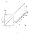
- FIG. 1 is a schematic perspective view of a frame structure in which a subframe manufactured by a manufacturing method according to an embodiment of the present invention is employed. It is a schematic perspective view of the sub-frame shown in FIG.
- FIG. 3 is a cross-sectional view taken along the line III-III shown in FIG. It is a figure which shows the condition which pinched
- FIG. 9B is a sectional view taken along line IX-IX shown in FIG. 9A. It is a figure which shows the condition when welding the contact part of the front-end
- FIGS. 1-10 a frame structure 100 employing a subframe (a dissimilar material joined body) manufactured by a manufacturing method according to an embodiment of the present invention will be described with reference to FIGS.
- the frame structure 100 in the present embodiment supports a vehicle engine such as an automobile, a speed reducer, and the like, and is attached with support parts for the suspension.
- the frame structure 100 includes a pair of side frames 1 and 2 extending in the front-rear direction A, and a subframe 3 extending in the left-right direction B and connecting the pair of side frames 1 and 2. 4.
- the side frames 1 and 2 of this embodiment are comprised from the steel square pipe, it does not specifically limit.
- the subframe 3 includes a first frame member 11 and a second frame member 12 disposed on the upper side of the first frame member 11, and has a substantially square pipe shape.
- the first frame member 11 is configured by bending a steel plate (Fe-based alloy plate or Fe plate) so that a concave portion 11a and a pair of flanges 11b extending in the left-right direction B are formed.
- the second frame member 12 is configured by bending an AL-based alloy plate (or AL plate) so that a recess 12a extending in the left-right direction B and a pair of flanges 12b are formed.
- the second frame member 12 is made of a material different from that of the first frame member 11.
- Each of the flanges 12b of the second frame member 12 is formed with a plurality of through holes 12c penetrating in the thickness direction as shown in FIG.
- the plurality of through holes 12 c are arranged at equal intervals along the left-right direction B.
- the through hole 12c has a circular planar shape.
- the sub-frame 3 has a pair of plates 13 respectively disposed on the flange 12b of the second frame member 12, as shown in FIG. That is, the plate 13 is disposed at a position where the flange 12 b of the second frame member 12 is sandwiched between the plate 13 and the flange 11 b of the first frame member 11.
- the plate 13 is made of a steel plate (Fe-based alloy plate or Fe plate) made of the same material as that of the first frame member 11 and extends long in the left-right direction B. As shown in FIG.
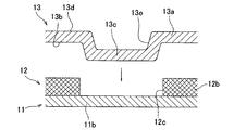
- the plate 13 is formed on the upper surface 13d by forming a plate body 13a extending in the left-right direction B, a plurality of protrusions 13c partially protruding from the lower surface 13b of the plate body 13a, and the protrusions 13c.
- a plurality of holes 13e are arranged at equal intervals along the left-right direction B corresponding to the through holes 12c of the flange 12b.
- the plurality of protrusions 13c have a circular planar shape and are formed in a size that can be inserted into the through hole 12c. That is, the diameter of the protrusion 13c is smaller than the diameter of the through hole 12c.
- the protrusion length of the protrusion 13c from the lower surface 13b of the plate 13 is such a length that the protrusion 13c can contact the flange 11b when the plate 13 is disposed on the flange 12b.
- the thickness of the flange 12b It is formed in the almost same length.
- the plate 13 is welded to the flange 11 b of the first frame member 11 with the plurality of protrusions 13 c inserted into the through holes 12 c formed in the flange 12 b of the second frame member 12. .
- the flange 12b of the second frame member 12 is sandwiched between the flange 11b of the first frame member 11 and the plate 13. In this way, the flanges 11b and 12b, which are overlapping portions of the first frame member 11 and the second frame member 12, are joined together to form the subframe 3.
- the manufacturing method of the subframe 3 includes a bonding method for bonding these dissimilar materials.
- the joining method in the present embodiment includes a projection forming process, a through hole forming process, a first frame member forming process, a second frame member forming process, a laminating process, a welding process, and the like, which will be described later.
- the protrusion 13c is formed on the plate body 13a by press working (protrusion forming step). That is, as shown in FIG. 4A, the plate body 13a before the protrusions 13c are formed is sandwiched between the die 101 and the blank holder 102. The die 101 and the blank holder 102 sandwich the periphery of the predetermined area S1 where the projection 13c of the plate body 13a is formed. Thereafter, as shown in FIG. 4B, a predetermined area S1 of the plate body 13a is pressed with a cylindrical punch 103. Thus, the protrusion 13c is formed on the plate 13.
- a hole 13e that is recessed due to the formation of the protrusion 13c is formed in the upper surface 13d of the plate body 13a.
- a plurality of holes 13e are formed in the plate 13 together with a plurality of protrusions 13c.
- the plurality of protrusions 13 c and the plurality of holes 13 e may be formed at once by the plurality of punches 103. Also in this case, it is preferable that the periphery of each of the predetermined regions S1 of the plate body 13a where the protrusions 13c are formed is sandwiched between the die 101 and the blank holder 102.
- the subframe 3 in order to manufacture the subframe 3, as shown in FIG. 5A and FIG. 5B, it is an AL-based alloy plate that forms the second frame member 12 before the recess 12a and the pair of flanges 12b are formed.
- a plurality of through holes 12c are formed by press working in a portion corresponding to 12b (through hole forming step). That is, as shown in FIG. 5A, a portion corresponding to the flange 12b of the AL alloy plate is sandwiched between the die 111 and the blank holder 112. The die 111 and the blank holder 112 sandwich the periphery of the predetermined region S2 where the through hole 12c of the flange 12b is formed. Thereafter, as shown in FIG.
- a predetermined area S2 of a portion corresponding to the flange 12b is punched out with a cylindrical punch 114.
- the punch 114 has a diameter slightly larger than the diameter of the punch 103 that forms the protrusion 13c.
- a through hole 12c having a diameter larger than that of the protrusion 13c is formed in a portion corresponding to the flange 12b. That is, the through-hole 12c into which the protrusion 13c can be inserted is formed in the laminating process described later.
- a plurality of through holes 12c are formed in a portion corresponding to the flange 12b of the second frame member 12.
- the plurality of through holes 12c may be formed by the plurality of punches 114 at once. Also in this case, it is preferable that the periphery of each of the predetermined regions S2 corresponding to the flange 12b where the through hole 12c is formed is sandwiched between the die 111 and the blank holder 112. Even if a plurality of through holes 12c are formed in the portion corresponding to the flange 12b by such a through hole forming step, burrs are hardly formed in the portion corresponding to the flange 12b.
- the through-hole forming step may be performed at any timing before the protrusion forming step, after the protrusion forming step, and at the same time as the protrusion forming step.
- the AL-based alloy plate in which the plurality of through holes 12c are formed is bent so as to form the recess 12a and the pair of flanges 12b.
- the second frame member 12 is formed (second frame member forming step).
- the steel plate constituting the first frame member 11 is bent so that the concave portion 11a and the pair of flanges 11b are formed.
- the first frame member 11 is formed (first frame member forming step).
- the 1st frame member formation process should just be performed before the below-mentioned lamination
- the flange 12b of the second frame member 12 is laminated on the flange 11b of the first frame member 11, and the flanges 11b and 12b are stacked. Overlap each other.
- the plate 13 is laminated on the flange 12b. That is, the flanges 11b and 12b and the plate 13 are laminated so that the flange 12b is disposed between the flange 11b and the plate 13 (lamination process).
- each of the protrusions 13c of the plate 13 is inserted into the plurality of through holes 12c of the flange 12b, and the tips of the protrusions 13c are brought into contact with the flange 11b.
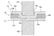
- the laminated body of the flanges 11b and 12b and the plate 13 is sandwiched between a pair of cylindrical electrodes 121 and 122 of a known spot welder as shown in FIG. 6B.
- the electrode 121 is disposed in the hole 13e so as to face the protrusion 13c
- the electrode 122 is disposed so as to face a region facing the protrusion 13c of the flange 11b.
- a welding current is sent between a pair of electrodes 121,122, pressurizing a laminated body with a pair of electrodes 121,122 to the lamination direction (the middle up-down direction of FIG. 6A and 6B).
- a welding current is passed between the pair of electrodes 121 and 122 while sandwiching a region facing the projection 13c and the projection 13c of the flange 11b so that the projection 13c is pressed against the flange 11b by the pair of electrodes 121 and 122 (welding process). ).
- the contact portion between the tip of the protrusion 13c and the flange 11b is melted and joined.
- the plurality of protrusions 13c of the plate 13 and the flange 11b are welded.
- a plurality of projections 13c may be welded to the flange 11b at a time with a plurality of pairs of electrodes 121 and 122.
- the flange 11b of the first frame member 11 and the plate 13 are interposed. With the flange 12b of the second frame member 12 being sandwiched, the flange 11b and the plate 13 are welded via the protrusion 13c. Thereby, the subframes 3 and 4 (dissimilar types) in which the portions where the first frame member 11 and the second frame member 12 made of different materials are overlapped (that is, the portion where the pair of flanges 11b and 12b are overlapped) are joined. Material joined body) can be manufactured.
- the protrusions 13c By forming the protrusions 13c in advance in the protrusion forming step in the manufacturing method and the joining method, it is difficult to form wrinkles at the time of forming the protrusions on the plate 13. For this reason, when spot-welding the protrusion 13c and the flange 11b, spatter is hardly generated, the welding quality is improved, and the joining strength is also improved. Further, since the projection 13c formed in advance on the plate 13 is brought into contact with the flange 11b and a welding current is passed from the pair of electrodes 121 and 122, the projection 13c and the flange 11b are welded. It is not necessary to form the protrusion 13c with the formed electrode 121, and the life of the electrode 121 is extended.
- the protrusion 13c is formed not by the electrode 121 but by the dedicated punch 103, the shape error of the protrusion 13c is less likely to occur and the welding quality is stabilized. Since the welding quality is improved and stabilized in this way, the bonding strength of the portion where the flange 11b of the first frame member 11 and the flange 12b of the second frame member 12 of different materials are overlapped is improved and stabilized. The life of 121 is also prolonged.
- the protrusion 13c of the plate 13 is welded to the flange 11b in a state where the protrusion 13c is inserted into the through hole 12c of the flange 12b.
- the part which piled up the flange 11b of the 1st frame member 11 and the flange 12b of the 2nd frame member 12 from which a material differs is joined more firmly.
- the projection 13c and the flange 11b are made to flow by passing a welding current between the pair of electrodes 121 and 122 while sandwiching the region facing the projection 13c and the projection 13c of the flange 11b between the pair of electrodes 121 and 122. Spot welding. Thereby, the welding quality of the protrusion 13c of the plate 13 and the flange 11b is further improved.
- a portion where the flange 11b of the first frame member 11 and the flange 12b of the second frame member 12 are overlapped is joined using a plate 13 which is a member different from these members.
- the pressing portion 113 corresponding to the plate 13 may be formed integrally with the flange 11b.
- a pressing portion 113 formed by folding a steel plate constituting the first frame member 11 is formed.
- the holding part 113 is arrange
- the pressing portion 113 is the same as that in which the plate 13 is integrally connected to the end portion along the left-right direction B of the flange 11b.
- the manufacturing method and joining method of the subframe 3 in the first modification are substantially the same except that the above-described protrusion forming step, first frame member forming step, and stacking step are slightly different. That is, in the protrusion forming step, the protrusions 13c are formed by press working in the same manner as the above-described plate 13 in the portion corresponding to the pressing portion 113 of the steel plate constituting the first frame member 11. In the first frame member forming step, the steel plate constituting the first frame member 11 formed with the plurality of protrusions 13c and the plurality of holes 13e is bent so that the recess 11a and the pair of flanges 11b are formed.
- the portion corresponding to the pressing portion 113 is arranged in the same plane as the flange 11b without being bent.
- the flange 12b of the second frame member 12 is stacked on the flange 11b of the first frame member 11, and the flanges 11b and 12b are overlapped.
- the portion corresponding to the pressing portion 113 of the steel plate constituting the first frame member 11 is bent so that the flange 12b is sandwiched between the pressing portion 113 and the flange 11b.
- 113 and flanges 11b and 12b are laminated.
- each of the protrusions 13c of the pressing portion 113 is inserted into the plurality of through holes 12c of the flange 12b, and the tips of the protrusions 13c are brought into contact with the flange 11b.
- the overlapping process of the flange 12b and the flange 11b between the press part 113 and the flange 11b is joined by performing a welding process similarly to the above-mentioned embodiment, and the sub-frame 3 is manufactured.
- the above-described joining method can be used for other than the subframe 3.
- a side frame 202 to be joined to a rail roof side 201 included in a vehicle side frame such as an automobile and a portion where the side frame 202 and a roof frame 203 made of different materials are overlapped are joined. It is also possible to do.
- the rail roof side 201 is closed by a steel plate (Fe-based alloy plate or Fe plate), and the upper flange 201a and the lower flange 201b are overlapped in the vertical direction and joined by welding.
- the side frame 202 is configured by bending a steel plate (Fe-based alloy plate or Fe plate), and is disposed outside the rail roof side 201.
- the side frame 202 includes a flange 202a, a curved portion 202b, and a connecting portion 202c that connects the flange 202a and the curved portion 202b.
- the flange 202a is overlapped with the flange 201a of the rail roof side 201 in the vertical direction and joined by welding.
- the roof frame 203 is configured by bending an AL-based alloy plate (or AL plate).
- the roof frame 203 includes a flange 203a, a curved roof portion 203b, and a connecting portion 203c that connects the flange 203a and the roof portion 203b.
- the flange 203a is overlapped and joined to the flange 202a in the vertical direction.
- a through hole 203d is formed in the flange 203a so as to penetrate in the thickness direction (vertical direction).
- the through hole 203d has a circular planar shape.
- the plate 204 is laminated on the flange 203a of the roof frame 203.
- the plate 204 is made of a steel plate (Fe alloy plate or Fe plate) made of the same material as the side frame 202, and extends in the direction perpendicular to the paper surface in FIG.
- the plate 204 has a plate main body 204a, a protrusion 204c partially protruding from the lower surface 204b of the plate main body 204a, and a hole 204e formed in the upper surface 204d by the formation of the protrusion 204c.
- the protrusion 204c and the hole 204e are disposed at a position facing the through hole 202d of the flange 202a.
- the protrusion 204c has a circular plane shape and is sized to be inserted into the through hole 203d. That is, the diameter of the protrusion 204c is smaller than the diameter of the through hole 203d.
- the protrusion length of the protrusion 204c from the lower surface 204b of the plate 204 is such a length that the protrusion 204c can come into contact with the flange 202a when the plate 204 is disposed on the flange 203a, and in this modification, the thickness of the flange 203a. It is formed in the almost same length.
- the plate 204 has the projection 204c inserted into the through hole 203d, and the tip of the projection 204c is welded to the flange 202a.
- the flange 203 a of the roof frame 203 is sandwiched between the flange 202 a of the side frame 202 and the plate 204.
- the flanges 202a and 203a which are overlapping portions of the side frame 202 and the roof frame 203, are joined.
- the joining method of the side frame 202 and the roof frame 203 is almost the same as that of the above-described embodiment. That is, in the protrusion forming step, the protrusion 204c is formed on the plate main body 204a by pressing as in the above-described embodiment. In the through hole forming step, the through hole 203d is formed by pressing in the portion corresponding to the flange 203a which is an AL-based alloy plate constituting the roof frame 203, as in the above embodiment. After the through hole forming step, the AL alloy plate is bent to form the roof frame 203 (roof frame forming step). Further, the side frames 202 are formed by bending the steel plates constituting the side frames 202 (side frame forming step).
- the flange 203a of the roof frame 203 is laminated on the flange 202a of the side frame 202, and the flanges 202a and 203a are overlapped with each other.
- the plate 204 is laminated on the flange 203a. That is, the flanges 202a and 203a and the plate 204 are laminated so that the flange 203a is disposed between the flange 202a and the plate 204 (lamination process).
- the projection 204c of the plate 204 is inserted into the through hole 203d of the flange 203a, and the tip of the projection 204c is brought into contact with the flange 202a.
- the laminate of the flanges 202a and 203a and the plate 204 is sandwiched between the pair of electrodes. That is, a welding current is passed between the pair of electrodes while sandwiching a region facing the projection 204c and the projection 204c of the flange 202a so that the projection 204c is pressed against the flange 202a by the pair of electrodes (welding process).
- the through hole 12c for inserting the protrusion 13c is formed in the flange 12b.
- the flange 12b has a notch 12c1 instead of the through hole 12c. May be formed.
- the notch 12c1 is released toward the outside in the direction orthogonal to the left-right direction B (downward in FIG. 9A).
- the notch portion forming step of forming the notch portion 12c1 in the flange 12b by pressing instead of the through hole 12c is a through hole. What is necessary is just to replace with a formation process. In the stacking step, as shown in FIG.
- the protrusion 13c is inserted into the notch 12c1, and the plate 13 and the flanges 11b and 12b are stacked. Then, the 1st frame member 11 and the 2nd frame member 12 are joined by performing the welding process similar to the above-mentioned embodiment, and the effect similar to the above can be acquired.
- the region of the protrusion 13c and the flange 11b facing the protrusion 13c is sandwiched between the pair of electrodes 121 and 122, and the protrusions 13c are welded to the flange 11b one by one.
- the plurality of protrusions 13c may be welded to the flange 11b at a time.
- a pair of electrodes extending in the left-right direction B so as to sandwich a plurality of regions facing the plurality of projections 13c and the projection 13c of the flange 11b. 221 and 222 are adopted.
- the pair of electrodes 221 and 222 sandwich the plurality of regions facing the protrusion 13c and the protrusion 13c of the flange 11b so as to press the plurality of protrusions 13c against the flange 11b, and between the pair of electrodes 221 and 222. Let the welding current flow through Thereby, the contact location of the front-end
- the plurality of through holes 12c into which the protrusions 13c can be inserted one by one are formed in the flange 12b.
- a through hole 12c2 having a size capable of inserting 13c may be formed.
- the through hole 12 c 2 has a long hole shape that is long along the left-right direction B.
- the through hole 12c2 in the through hole forming step, may be formed in the flange 12b by press working instead of the through hole 12c. .
- a plurality of projections 13c are inserted in penetration hole 12c2, and plate 13 and flanges 11b and 12b are laminated. Then, the 1st frame member 11 and the 2nd frame member 12 are joined by performing the welding process similar to the above-mentioned embodiment, and the effect similar to the above can be acquired.
- the notch 12c1 of the third modification is a long notch similar to the above-described through-hole 12c2, and a plurality of protrusions 13c are inserted into the notch in the stacking step, and the plate 13 and the flange 11b , 12b may be laminated.
- the region facing the protrusion 13c of the flange 11b is flat, but a protrusion protruding toward the protrusion 13c may be formed in the region of the flange 11b.
- the present invention is not limited to the above-described embodiments, and various modifications can be made as long as they are described in the claims.
- the joining method and the manufacturing method in the above-described embodiment and each modification the first metal member and the second metal member made of a material different from the first metal member are used for joining the overlapping portions. Can do. That is, the joining method and the manufacturing method are not limited to the production of the subframes 3 and 4 described above, and can be adopted for joining different metal members.
- the first frame member 11 is made of Fe-based alloy or Fe, but may be made of aluminum alloy or aluminum.
- the plate 13 may also be made of an aluminum alloy or aluminum, and the second frame member 12 may be made of, for example, an Fe-based alloy or Fe.
- the 1st frame member 11 and the plate 13 may be comprised from what kind of metal, as long as it was comprised from the metal of the same material which can be welded.
- the second frame member 12 may be made of any metal as long as it is made of a metal different from the first frame member 11 and the plate 13.
- the through hole forming step or the notch portion forming step is included, but the through hole forming step or the notch portion forming step may not be included.
- the protrusion 13c is not inserted into the through hole 12c, but the flange 12b is simply disposed between the flange 11b and the plate 13, and the protrusion 13c and the flange 11b are welded in the welding process. It is only necessary that the flange 12b is sandwiched between the flange 11b and the plate 13 and the overlapping portions of the flanges 11b and 12b are joined. Even in this case, the same effect as described above can be obtained.
- the through holes 12c and 12c2 are formed by pressing, but the through holes may be formed by a drill or the like. Further, the shapes of the protrusions 13c and 204c and the through holes 12c, 12c2 and 203d may have a polygonal or elliptical planar shape, or may have a planar shape elongated in one direction, for example. Good.
- Subframe (dissimilar material joint) 11 First frame member (first metal member) 12 Second frame member (second metal member) 12c, 12c2, 203d Through-hole 13,204 Plate (third metal member) 13c, 204c Projection 101, 111 Die 102, 112 Blank holder 103, 114 Punch 113 Holding part (third metal member) 121, 122, 221, 222 Electrode 202 Side frame (first metal member) 203 Roof frame (second metal member) S1, S2 predetermined area
Landscapes
- Engineering & Computer Science (AREA)
- Mechanical Engineering (AREA)
- Chemical & Material Sciences (AREA)
- Combustion & Propulsion (AREA)
- Transportation (AREA)
- Resistance Welding (AREA)
- Body Structure For Vehicles (AREA)
- Shaping Metal By Deep-Drawing, Or The Like (AREA)
Abstract
第1フレーム部材(11)と第2フレーム部材(12)とを接合する接合方法は、プレート(13)の所定領域にプレス加工で突起(13c)を形成する突起形成工程と、プレート(13)の突起(13c)の先端をフランジ(11b)に接触させるとともに、フランジ(11b)とプレート(13)との間にフランジ(12b)を配置させるように、フランジ(11b,12b)及びプレート(13)を積層する積層工程と、一対の電極(121,122)で突起(13c)をフランジ(11b)に押圧するように積層体を挟み、当該一対の電極(121,122)間に溶接電流を流して突起(13c)をフランジ(11b)に溶接する溶接工程とを含む。
Description
本発明は、材質が異なる二種の金属部材を重ね合わせた部分の接合方法、及び、異種材接合体の製造方法に関する。
特許文献1には、AL系合金板よりも高い融点を持つ鋼板及び円形ブランクで当該合金板を挟むように積層された積層体を、一対の電極で加圧すると共に一対の電極間に溶接電流を流して、鋼板に円形ブランクをスポット溶接する接合方法について記載されている。この接合方法においては、一対の電極による加圧通電下で生じた円形ブランク中央部分の塑性変形による膨出変形部分が合金板の溶融部分を排除して鋼板にスポット溶接される。こうして、材質が異なる合金板及び鋼板を重ね合わせた部分が接合される。
しかしながら、上記特許文献1に記載の接合方法においては、円形ブランクを電極で単に押圧して膨出変形部分を形成しているため、円形ブランクの膨出変形部分近傍には膨出変形部分形成時に皺が形成される。また、円形ブランクの膨出変形部分は、電極が円形ブランクに馴染みにくいため、安定した張出し形状とならず凹凸が形成されやすい。このため、円形ブランクの膨出変形部分を鋼板に溶接する際に鋼板と異材の間に空間ができ、スパッタが発生しやすくなる。このため、溶接品質が劣化し、接合強度も低下する。また、膨出変形部分が電極による押圧によって形成されるため、電極の磨耗が大きい。このため、形成された膨出変形部分に形状差が生じ、膨出変形部分毎の鋼板との溶接品質にばらつきが生じる。さらに、電極の磨耗が大きいため、電極の寿命が短くなる。このような溶接品質の低下及びばらつきに伴い、材質が異なる合金板及び鋼板を重ね合わせた部分の接合強度の低下及びばらつきが生じるとともに、電極の寿命が短くなるという問題が生じる。
そこで、本発明の目的は、材質が異なる第1の金属部材と第2の金属部材とを重ね合わせた部分の接合強度が向上すると共に安定し、電極の寿命も長くすることが可能な接合方法及び異種材接合体の製造方法を提供することである。
本発明の一態様の接合方法は、第1の金属部材と、前記第1の金属部材と異なる材質の第2の金属部材とを重ね合わせた部分の接合方法において、前記第1の金属部材及び前記第1の金属部材と同じ材質の第3の金属部材のうちの少なくとも前記第3の金属部材の所定領域の周囲をダイ及びブランクホルダで挟み、当該所定領域をパンチで押圧することで前記第3の金属部材に1以上の突起を形成する突起形成工程と、前記突起形成工程で形成された前記第3の金属部材の前記突起の先端を前記第1の金属部材に接触させるとともに、前記第1の金属部材と前記第3の金属部材との間に前記第2の金属部材を配置させるように、前記第1、第2及び第3の金属部材を積層する積層工程と、前記積層工程によって積層された積層体の積層方向において、一対の電極で前記突起を前記第1の金属部材に押圧するように前記積層体を挟み、当該一対の電極間に溶接電流を流して前記突起を前記第1の金属部材に溶接する溶接工程とを備えている。
これによると、第1の金属部材と第3の金属部材との間に第2の金属部材が挟まれた状態で、突起を介して第1の金属部材と第3の金属部材とが溶接される。これにより、材質が異なる第1の金属部材と第2の金属部材とを重ね合わせた部分が接合される。この接合方法における突起形成工程で予め1以上の突起を形成することで、突起形成時の皺が金属部材に形成されにくくなる。このため、突起と第1の金属部材とを溶接する際に、スパッタが発生しにくくなって溶接品質が向上し、接合強度も向上する。また、第3の金属部材に予め形成された1以上の突起を第1の金属部材に接触させて一対の電極から溶接電流を流すことで、突起と第1の金属部材とを溶接しているため、電極で突起を形成する必要がなくなって、電極の寿命が長くなるとともに、突起の形状誤差が生じにくくなって溶接品質が安定する。このように溶接品質が向上すると共に安定するため、材質が異なる第1の金属部材と第2の金属部材とを重ね合わせた部分の接合強度が向上すると共に安定し、電極の寿命も長くなる。
本発明の一態様において、前記第2の金属部材の所定領域に1以上の前記突起を挿入することが可能な大きさの1以上の貫通孔を形成する貫通孔形成工程をさらに備えている。そして、前記積層工程において、1以上の前記突起を前記貫通孔に挿入しつつ前記第1、第2及び第3の金属部材を積層することが好ましい。これにより、材質が異なる第1の金属部材と第2の金属部材とを重ね合わせた部分がより強固に接合される。
また、本発明の一態様において、前記貫通孔形成工程において、前記第2の金属部材の所定領域の周囲をダイ及びブランクホルダで挟み、当該所定領域をパンチで打ち抜くことで前記貫通孔を形成することが好ましい。これにより、貫通孔形成時に第2の金属部材にバリが形成されにくくなる。このため、材質が異なる第1の金属部材と第2の金属部材とを重ね合わせた部分がより一層強固に接合される。
また、本発明の一態様において、前記溶接工程において、前記一対の電極で前記突起及び前記第1の金属部材の前記突起と対向する領域を挟みつつ当該一対の電極間に溶接電流を流すことが好ましい。これにより、第3の金属部材に形成された突起と第1の金属部材との溶接品質がより向上する。
また、本発明の一態様において、前記突起形成工程において、前記第3の金属部材に複数の前記突起が形成され、前記溶接工程において、前記一対の電極で前記複数の突起及び前記第1の金属部材の前記複数の突起と対向する領域を挟みつつ当該一対の電極間に溶接電流を流すことが好ましい。これにより、第3の金属部材に形成された複数の突起を第1の金属部材に効果的に溶接することが可能となる。
また、本発明の一態様の異種材接合体の製造方法は、第1の金属部材と、前記第1の金属部材と異なる材質の第2の金属部材とを重ね合わせて接合された異種材接合体の製造方法において、前記第1の金属部材及び前記第1の金属部材と同じ材質の第3の金属部材のうちの少なくとも前記第3の金属部材の所定領域の周囲をダイ及びブランクホルダで挟み、当該所定領域をパンチで押圧することで前記第3の金属部材に1以上の突起を形成する突起形成工程と、前記突起形成工程で形成された前記第3の金属部材の前記突起の先端を前記第1の金属部材に接触させると共に、前記第1の金属部材と前記第3の金属部材との間に前記第2の金属部材を配置させるように、前記第1、第2及び第3の金属部材を積層する積層工程と、前記積層工程によって積層された積層体の積層方向において、一対の電極で前記突起を前記第1の金属部材に押圧するように前記積層体を挟み、当該一対の電極間に溶接電流を流して前記突起を前記第1の金属部材に溶接する溶接工程とを備えている。
これによると、第1の金属部材と第3の金属部材との間に第2の金属部材が挟まれた状態で、突起を介して第1の金属部材と第3の金属部材とが溶接される。これにより、材質が異なる第1の金属部材と第2の金属部材とを重ね合わせた部分が接合された異種材接合体を製造することができる。この製造方法における突起形成工程で予め1以上の突起を形成することで、突起形成時の皺が金属部材に形成されにくくなる。このため、突起と第1の金属部材とを溶接する際に、スパッタが発生しにくくなって溶接品質が向上し、接合強度も向上する。また、第3の金属部材に予め形成された1以上の突起を第1の金属部材に接触させて一対の電極から溶接電流を流すことで、突起と第1の金属部材とを溶接しているため、電極で突起を形成する必要がなくなって、電極の寿命が長くなるとともに、突起の形状誤差が生じにくくなって溶接品質が安定する。このように溶接品質が向上すると共に安定するため、材質が異なる第1の金属部材と第2の金属部材とを重ね合わせた部分の接合強度が向上すると共に安定し、電極の寿命も長くなる。
本発明の一態様の接合方法によると、第1の金属部材と第3の金属部材との間に第2の金属部材が挟まれた状態で、突起を介して第1の金属部材と第3の金属部材とが溶接される。これにより、材質が異なる第1の金属部材と第2の金属部材とを重ね合わせた部分が接合される。この接合方法における突起形成工程で予め1以上の突起を形成することで、突起形成時の皺が金属部材に形成されにくくなる。このため、突起と第1の金属部材とを溶接する際に、スパッタが発生しにくくなって溶接品質が向上し、接合強度も向上する。また、第3の金属部材に予め形成された1以上の突起を第1の金属部材に接触させて一対の電極から溶接電流を流すことで、突起と第1の金属部材とを溶接しているため、電極で突起を形成する必要がなくなって、電極の寿命が長くなるとともに、突起の形状誤差が生じにくくなって溶接品質が安定する。このように溶接品質が向上すると共に安定するため、材質が異なる第1の金属部材と第2の金属部材とを重ね合わせた部分の接合強度が向上すると共に安定し、電極の寿命も長くなる。
また、本発明の一態様の異種材接合体の製造方法によると、第1の金属部材と第3の金属部材との間に第2の金属部材が挟まれた状態で、突起を介して第1の金属部材と第3の金属部材とが溶接される。これにより、材質が異なる第1の金属部材と第2の金属部材とを重ね合わせた部分が接合された異種材接合体を製造することができる。この製造方法における突起形成工程で予め1以上の突起を形成することで、突起形成時の皺が金属部材に形成されにくくなる。このため、突起と第1の金属部材とを溶接する際に、スパッタが発生しにくくなって溶接品質が向上し、接合強度も向上する。また、第3の金属部材に予め形成された1以上の突起を第1の金属部材に接触させて一対の電極から溶接電流を流すことで、突起と第1の金属部材とを溶接しているため、電極で突起を形成する必要がなくなって、電極の寿命が長くなるとともに、突起の形状誤差が生じにくくなって溶接品質が安定する。このように溶接品質が向上すると共に安定するため、材質が異なる第1の金属部材と第2の金属部材とを重ね合わせた部分の接合強度が向上すると共に安定し、電極の寿命も長くなる。
また、本発明の一態様の異種材接合体の製造方法によると、第1の金属部材と第3の金属部材との間に第2の金属部材が挟まれた状態で、突起を介して第1の金属部材と第3の金属部材とが溶接される。これにより、材質が異なる第1の金属部材と第2の金属部材とを重ね合わせた部分が接合された異種材接合体を製造することができる。この製造方法における突起形成工程で予め1以上の突起を形成することで、突起形成時の皺が金属部材に形成されにくくなる。このため、突起と第1の金属部材とを溶接する際に、スパッタが発生しにくくなって溶接品質が向上し、接合強度も向上する。また、第3の金属部材に予め形成された1以上の突起を第1の金属部材に接触させて一対の電極から溶接電流を流すことで、突起と第1の金属部材とを溶接しているため、電極で突起を形成する必要がなくなって、電極の寿命が長くなるとともに、突起の形状誤差が生じにくくなって溶接品質が安定する。このように溶接品質が向上すると共に安定するため、材質が異なる第1の金属部材と第2の金属部材とを重ね合わせた部分の接合強度が向上すると共に安定し、電極の寿命も長くなる。
以下、本発明の一実施形態に係る製造方法によって製造されたサブフレーム(異種材接合体)が採用されたフレーム構造体100について、図1~図3を参照しつつ以下に説明する。
本実施形態におけるフレーム構造体100は、自動車などの車両のエンジンや減速機などを支え、足回りの支持部品などが取り付けられるものである。フレーム構造体100は、図1に示すように、前後方向Aに延在する一対のサイドフレーム1,2と、左右方向Bに延在し一対のサイドフレーム1,2間を繋ぐサブフレーム3,4とを有する。本実施形態のサイドフレーム1,2は、鋼製の角パイプから構成されているが、特に限定するものではない。
サブフレーム3,4は、いずれも同じ構成を有しているため、一方のサブフレーム3について説明し、サブフレーム4の説明を省略する。サブフレーム3は、図2に示すように、第1フレーム部材11と、第1フレーム部材11の上側に配置された第2フレーム部材12とを有し、略角パイプ形状を有する。第1フレーム部材11は、左右方向Bに延在する凹部11a及び一対のフランジ11bが形成されるように、鋼板(Fe系合金板またはFe板)が折り曲げられて構成されている。
第2フレーム部材12は、左右方向Bに延在する凹部12a及び一対のフランジ12bが形成されるように、AL系合金板(又はAL板)が折り曲げられて構成されている。このように第2フレーム部材12は、第1フレーム部材11とは異なる材質から構成されている。第2フレーム部材12のフランジ12bのそれぞれには、図3に示すように、厚み方向に貫通する複数の貫通孔12cが形成されている。複数の貫通孔12cは、左右方向Bに沿って等間隔に配置されている。貫通孔12cは、円形平面形状を有する。
サブフレーム3は、図2に示すように、第2フレーム部材12のフランジ12b上にそれぞれ配置された一対のプレート13を有する。つまり、プレート13は、第1フレーム部材11のフランジ11bとの間に第2フレーム部材12のフランジ12bを挟む位置に配置されている。プレート13は、第1フレーム部材11と同じ材質の鋼板(Fe系合金板またはFe板)からなり、左右方向Bに長尺に延在している。プレート13は、図3に示すように、左右方向Bに延在するプレート本体13aと、プレート本体13aの下面13bから部分的に突出した複数の突起13cと、突起13cの形成によって上面13dに形成された複数の穴13eとを有する。これら複数の突起13cと複数の穴13eは、フランジ12bの貫通孔12cに対応して、左右方向Bに沿って等間隔に配置されている。また、複数の突起13cは、円形平面形状を有し、貫通孔12cに挿通可能なサイズに形成されている。つまり、突起13cの直径は、貫通孔12cの直径よりも小さく形成されている。また、プレート13の下面13bからの突起13cの突出長は、プレート13をフランジ12b上に配置したときに突起13cがフランジ11bと接触可能な長さであり、本実施形態においてはフランジ12bの厚みとほぼ同じ長さに形成されている。
プレート13は、複数の突起13cが第2フレーム部材12のフランジ12bに形成された貫通孔12cに挿入された状態で、当該突起13cの先端が第1フレーム部材11のフランジ11bに溶接されている。これにより、第2フレーム部材12のフランジ12bが第1フレーム部材11のフランジ11bとプレート13との間で両者に挟まれる。こうして、第1フレーム部材11と第2フレーム部材12との重なり部分であるフランジ11b,12b同士が接合され、サブフレーム3が構成されている。
続いて、サブフレーム3の製造方法について、図4~図6を参照しつつ以下に説明する。サブフレーム3を製造する際は、互いに異なる材質からなる第1フレーム部材11と第2フレーム部材12とを接合する必要がある。つまり、サブフレーム3の製造方法には、これら異種材を接合する接合方法も含まれる。本実施形態における接合方法には、後述する、突起形成工程、貫通孔形成工程、第1フレーム部材形成工程、第2フレーム部材形成工程、積層工程、溶接工程などが含まれる。
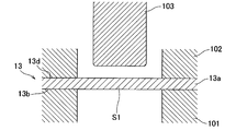
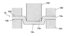
サブフレーム3を製造するには、図4に示すように、プレート本体13aに突起13cをプレス加工で形成する(突起形成工程)。つまり、図4Aに示すように、突起13cが形成される前のプレート本体13aをダイ101及びブランクホルダ102で挟む。ダイ101及びブランクホルダ102は、プレート本体13aの突起13cが形成される所定領域S1の周囲を挟む。この後、図4Bに示すように、円柱状のパンチ103でプレート本体13aの所定領域S1を押圧する。こうして、プレート13に突起13cが形成される。このとき、プレート本体13aの上面13dには、突起13cの形成によって窪んだ穴13eが形成される。このような工程を繰り返し行うことでプレート13に複数の突起13cと共に複数の穴13eが形成される。なお、突起形成工程において、複数の突起13c及び複数の穴13eを、複数のパンチ103で一度に形成してもよい。この場合も、突起13cが形成されるプレート本体13aの所定領域S1のそれぞれの周囲は、ダイ101及びブランクホルダ102によって挟まれていることが好ましい。このような突起形成工程により、プレート13に複数の突起13cが形成されても、プレート本体13aに皺がほとんど形成されない。この結果、後述の溶接工程において、スパッタが生じにくくなる。
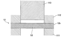
また、サブフレーム3を製造するには、図5A及び図5Bに示すように、凹部12aや一対のフランジ12bが形成される前の第2フレーム部材12を構成するAL系合金板であってフランジ12bに対応する部分に、複数の貫通孔12cをプレス加工で形成する(貫通孔形成工程)。つまり、図5Aに示すように、AL系合金板のフランジ12bに対応する部分をダイ111及びブランクホルダ112で挟む。ダイ111及びブランクホルダ112は、フランジ12bの貫通孔12cが形成される所定領域S2の周囲を挟む。この後、図5Bに示すように、円柱状のパンチ114でフランジ12bに対応する部分の所定領域S2を打ち抜く。パンチ114は、突起13cを形成するパンチ103の直径よりも若干大きな直径を有している。こうして、フランジ12bに対応する部分に直径が突起13cよりも大きい貫通孔12cが形成される。つまり、後述の積層工程において、突起13cを挿入することが可能な貫通孔12cが形成される。このような工程を繰り返し行うことで、第2フレーム部材12のフランジ12bに対応する部分に複数の貫通孔12cが形成される。なお、貫通孔形成工程において、複数の貫通孔12cを、複数のパンチ114で一度に形成してもよい。この場合も、貫通孔12cが形成されるフランジ12bに対応する部分の所定領域S2のそれぞれの周囲は、ダイ111及びブランクホルダ112によって挟まれていることが好ましい。このような貫通孔形成工程により、フランジ12bに対応する部分に複数の貫通孔12cが形成されても、フランジ12bに対応する部分にバリがほとんど形成されない。この結果、後述の積層工程において、フランジ11b,12b及びプレート13を隙間なく積層させた状態で、突起13cと第1フレーム部材11とを溶接することが可能となる。このため、フランジ11b、12bの重ね合わせた部分がより一層強固に接合される。なお、貫通孔形成工程は、突起形成工程の前、突起形成工程の後、及び、突起形成工程と同時のいずれのタイミングに行われてもよい。
貫通孔形成工程の後、凹部12a及び一対のフランジ12bを形成するように、複数の貫通孔12cが形成されたAL系合金板を折り曲げる。こうして、第2フレーム部材12が形成される(第2フレーム部材形成工程)。
第1フレーム部材11を構成する鋼板を、凹部11a及び一対のフランジ11bが形成されるように折り曲げる。こうして、第1フレーム部材11が形成される(第1フレーム部材形成工程)。なお、第1フレーム部材形成工程は、後述の積層工程前に行われていればよい。
突起形成工程、第1及び第2フレーム部材形成工程の後に、図6Aに示すように、第1フレーム部材11のフランジ11b上に第2フレーム部材12のフランジ12bを積層して、フランジ11b,12b同士を重ね合わせる。その後、図6Bに示すように、プレート13をフランジ12b上に積層する。つまり、フランジ11bとプレート13との間にフランジ12bが配置されるように、フランジ11b,12b及びプレート13を積層する(積層工程)。このとき、プレート13の突起13cのそれぞれをフランジ12bの複数の貫通孔12cに挿入し、当該各突起13cの先端をフランジ11bに接触させる。
積層工程の後に、公知のスポット溶接機の円柱状の一対の電極121,122で、図6Bに示すように、フランジ11b,12b及びプレート13の積層体を挟む。このとき、電極121が突起13cと対向するように穴13e内に配置され、電極122がフランジ11bの突起13cと対向する領域と対向するように配置される。そして、一対の電極121,122で積層体を積層方向(図6A及び図6Bの中上下方向)に加圧しつつ、一対の電極121,122間に溶接電流を流す。つまり、一対の電極121,122で突起13cをフランジ11bに押圧するように、突起13c及びフランジ11bの突起13cと対向する領域を挟みつつ一対の電極121,122間に溶接電流を流す(溶接工程)。これにより、突起13cの先端とフランジ11bとの接触部分が溶融し接合される。このような工程を繰り返し行うことで、プレート13の複数の突起13cとフランジ11bとが溶接される。なお、複数対の電極121,122で複数の突起13cをフランジ11bに一度に溶接してもよい。こうして、プレート13とフランジ11bとの間にあるフランジ12bとフランジ11bとの重なり部分が接合され、サブフレーム3が製造される。
以上のように、サブフレーム3の製造方法及び第1フレーム部材11と第2フレーム部材12とを重ね合わせた部分の接合方法によると、第1フレーム部材11のフランジ11bとプレート13との間に第2フレーム部材12のフランジ12bが挟まれた状態で、突起13cを介してフランジ11bとプレート13とが溶接される。これにより、材質が異なる第1フレーム部材11と第2フレーム部材12とを重ね合わせた部分(すなわち、一対のフランジ11b,12b同士を重ね合わせた部分)が接合されたサブフレーム3,4(異種材接合体)を製造することができる。この製造方法及び接合方法における突起形成工程で予め突起13cを形成することで、突起形成時の皺がプレート13に形成されにくくなる。このため、突起13cとフランジ11bとをスポット溶接する際に、スパッタが発生しにくくなって溶接品質が向上し、接合強度も向上する。また、プレート13に予め形成された突起13cをフランジ11bに接触させて一対の電極121,122から溶接電流を流すことで、突起13cとフランジ11bとを溶接しているため、突起13c側に配置された電極121で突起13cを形成する必要がなくなって、電極121の寿命が長くなる。また、電極121ではなく専用のパンチ103で突起13cを形成しているため、突起13cの形状誤差が生じにくくなって溶接品質が安定する。このように溶接品質が向上すると共に安定するため、材質が異なる第1フレーム部材11のフランジ11bと第2フレーム部材12のフランジ12bとを重ね合わせた部分の接合強度が向上すると共に安定し、電極121の寿命も長くなる。
また、サブフレーム3の製造方法及び接合方法においては、第2フレーム部材12の一対のフランジ12bに、積層工程において、突起13cを挿入するための複数の貫通孔12cを形成する貫通孔形成工程が行われる。これにより、プレート13の突起13cがフランジ12bの貫通孔12cに挿入された状態でフランジ11bに溶接される。このため、材質が異なる第1フレーム部材11のフランジ11bと第2フレーム部材12のフランジ12bとを重ね合わせた部分がより強固に接合される。
また、溶接工程では、一対の電極121,122で突起13cとフランジ11bの突起13cと対向する領域を挟みつつ一対の電極121,122間に溶接電流を流すことで、突起13cとフランジ11bとをスポット溶接している。これにより、プレート13の突起13cとフランジ11bとの溶接品質がより向上する。
上述の実施形態におけるサブフレーム3は、第1フレーム部材11のフランジ11bと第2フレーム部材12のフランジ12bとを重ね合わせた部分を、これら部材とは別部材のプレート13を用いて接合していたが、プレート13に相当する押さえ部113がフランジ11bに一体的に形成されていてもよい。この第1変形例における第1フレーム部材11のフランジ11bの端部には、図7に示すように、第1フレーム部材11を構成する鋼板が折り返されてなる押さえ部113が形成されている。押さえ部113は、フランジ11bとの間においてフランジ12bを挟む位置に配置されている。押さえ部113は、上述のプレート13がフランジ11bの左右方向Bに沿う端部に一体的に接続されたものと同様のものである。
第1変形例におけるサブフレーム3の製造方法及び接合方法では、上述の突起形成工程、第1フレーム部材形成工程、積層工程が若干異なるだけでそれ以外はほぼ同様である。つまり、突起形成工程では、第1フレーム部材11を構成する鋼板の押さえ部113に対応する部分に、上述のプレート13と同様に突起13cをプレス加工で形成する。第1フレーム部材形成工程では、複数の突起13c及び複数の穴13eが形成された第1フレーム部材11を構成する鋼板を、凹部11a及び一対のフランジ11bが形成されるように折り曲げる。このとき、押さえ部113に対応する部分は、折り曲げずにフランジ11bと同一平面状に配置させておく。積層工程では、第1フレーム部材11のフランジ11b上に第2フレーム部材12のフランジ12bを積層して、フランジ11b,12b同士を重ね合わせる。その後、図7に示すように、押さえ部113とフランジ11bとの間にフランジ12bが挟まれるように、第1フレーム部材11を構成する鋼板の押さえ部113に対応する部分を折り曲げて、押さえ部113,フランジ11b,12bを積層する。このとき、押さえ部113の突起13cのそれぞれをフランジ12bの複数の貫通孔12cに挿入し、当該各突起13cの先端をフランジ11bに接触させる。そして、上述の実施形態と同様に溶接工程が行われることで、押さえ部113とフランジ11bとの間にあるフランジ12bとフランジ11bとの重なり部分が接合され、サブフレーム3が製造される。
上述の接合方法は、サブフレーム3以外のものでも採用可能である。図8に示すように、例えば、自動車などの車体側部フレームに含まれるレールルーフサイド201に接合されるサイドフレーム202と、サイドフレーム202と材質の異なるルーフフレーム203とを重ね合わせた部分を接合することも可能である。レールルーフサイド201は、鋼板(Fe系合金板またはFe板)で閉断面化し、上側のフランジ201a及び下側のフランジ201bを上下方向に重ね合わせて溶接により接合されてなる。
サイドフレーム202は、鋼板(Fe系合金板またはFe板)が折り曲げられて構成されており、レールルーフサイド201の外側に配置されている。サイドフレーム202は、フランジ202aと、湾曲部202bと、フランジ202aと湾曲部202bとを繋ぐ繋ぎ部202cとを有する。フランジ202aは、レールルーフサイド201のフランジ201aと上下方向に重ね合わせて溶接により接合されている。
ルーフフレーム203は、AL系合金板(又はAL板)が折り曲げられて構成されている。ルーフフレーム203は、フランジ203aと、湾曲したルーフ部203bと、フランジ203aとルーフ部203bとを繋ぐ繋ぎ部203cとを有する。フランジ203aは、フランジ202aと上下方向に重ね合わせて接合されている。フランジ203aには、厚み方向(上下方向)に貫通する貫通孔203dが形成されている。貫通孔203dは、円形平面形状を有する。
ルーフフレーム203のフランジ203a上には、プレート204が積層されている。プレート204は、サイドフレーム202と同じ材質の鋼板(Fe系合金板またはFe板)からなり、図8中紙面垂直方向に延在している。プレート204はプレート本体204aと、プレート本体204aの下面204bから部分的に突出した突起204cと、突起204cの形成によって上面204dに形成された穴204eとを有する。突起204cと穴204eは、フランジ202aの貫通孔202dと対向する位置に配置されている。また、突起204cは、円形平面形状を有し、貫通孔203dに挿通可能なサイズに形成されている。つまり、突起204cの直径は、貫通孔203dの直径よりも小さく形成されている。また、プレート204の下面204bからの突起204cの突出長は、プレート204をフランジ203a上に配置したときに突起204cがフランジ202aと接触可能な長さであり、本変形例においてはフランジ203aの厚みとほぼ同じ長さに形成されている。
プレート204は、突起204cが貫通孔203dに挿入された状態で、当該突起204cの先端がフランジ202aに溶接されている。これにより、ルーフフレーム203のフランジ203aがサイドフレーム202のフランジ202aとプレート204との間に挟まれる。こうして、サイドフレーム202とルーフフレーム203との重なり部分であるフランジ202a,203a同士が接合される。
サイドフレーム202とルーフフレーム203との接合方法も上述の実施形態とほぼ同様である。つまり、突起形成工程では、プレート本体204aに突起204cを上述の実施形態と同様にプレス加工で形成する。貫通孔形成工程では、ルーフフレーム203を構成するAL系合金板であってフランジ203aに対応する部分に、貫通孔203dを上述の実施形態と同様にプレス加工で形成する。貫通孔形成工程の後、当該AL系合金板を折り曲げてルーフフレーム203を形成する(ルーフフレーム形成工程)。また、サイドフレーム202を構成する鋼板を折り曲げてサイドフレーム202を形成する(サイドフレーム形成工程)
突起形成工程、ルーフフレーム形成工程及びサイドフレーム形成工程の後に、サイドフレーム202のフランジ202a上にルーフフレーム203のフランジ203aを積層して、フランジ202a,203a同士を重ね合わせる。その後、プレート204をフランジ203a上に積層する。つまり、フランジ202aとプレート204との間にフランジ203aが配置されるように、フランジ202a,203a及びプレート204を積層する(積層工程)。このとき、プレート204の突起204cをフランジ203aの貫通孔203dに挿入し、当該突起204cの先端をフランジ202aに接触させる。この後、上述の実施形態と同様に、一対の電極でフランジ202a,203a及びプレート204の積層体を挟む。つまり、一対の電極で突起204cがフランジ202aに押圧されるように、突起204c及びフランジ202aの突起204cと対向する領域を挟みつつ一対の電極間に溶接電流を流す(溶接工程)。これにより、突起204cの先端とフランジ202aとの接触部分が溶融し接合される。こうして、プレート204とフランジ202aとの間にあるフランジ203aとフランジ202aとの重なり部分が接合される。この後、フランジ202aとレールルーフサイド201のフランジ201aとが溶接されることで、ルーフフレーム203と接合されたサイドフレーム202と、レールルーフサイド201とが接合される。
このような第2変形例においても、上述の実施形態と同様な部分においては、同じ効果を得ることが可能となる。
また、上述の実施形態においては、突起13cを挿入するための貫通孔12cがフランジ12bに形成されていたが、図9Aに示すように、フランジ12bには貫通孔12cに代えて切り欠き部12c1が形成されていてもよい。切り欠き部12c1は、左右方向Bと直交する方向の外側(図9A中下方)に向かって解放している。この第3変形例における第1フレーム部材11と第2フレーム部材12との接合方法では、貫通孔12cに代えて切り欠き部12c1をフランジ12bにプレス加工によって形成する切り欠き部形成工程が貫通孔形成工程に代えて行われればよい。そして、積層工程において、図9Bに示すように、突起13cが切り欠き部12c1に挿入され、プレート13、フランジ11b,12bが積層されればよい。この後、上述の実施形態と同様な溶接工程が行われることで、第1フレーム部材11と第2フレーム部材12とが接合され、上述と同様の効果を得ることができる。
また、上述の実施形態における溶接工程では、突起13c及びフランジ11bの突起13cと対向する領域を一対の電極121,122で個別に挟んで、突起13cを1つずつフランジ11bに溶接していたが、複数の突起13cをフランジ11bに一度に溶接してもよい。この第4変形例においては、図10に示すように、複数の突起13c及びフランジ11bの突起13cと対向する複数の領域を挟むことが可能なように、左右方向Bに延在する一対の電極221,222を採用する。そして、複数の突起13cをフランジ11bに押圧するように、当該一対の電極221,222で複数の突起13c及びフランジ11bの突起13cと対向する複数の領域を挟みつつ、一対の電極221,222間に溶接電流を流す。これにより、複数の突起13cの先端とフランジ11bとの接触箇所が溶融し、複数の突起13cをフランジ11bに効果的に溶接することが可能となる。
また、上述の実施形態においては、突起13cを1つずつ挿入することが可能な複数の貫通孔12cがフランジ12bに形成されていたが、図11に示すように、フランジ12bには複数の突起13cを挿入することが可能な大きさの貫通孔12c2が形成されていてもよい。貫通孔12c2は、左右方向Bに沿って長尺な長孔形状を有している。この第5変形例における第1フレーム部材11と第2フレーム部材12との接合方法では、貫通孔形成工程において、貫通孔12cに代えて貫通孔12c2がフランジ12bにプレス加工によって形成されればよい。そして、積層工程において、図11に示すように、複数の突起13cを貫通孔12c2に挿入し、プレート13、フランジ11b,12bを積層する。この後、上述の実施形態と同様な溶接工程が行われることで、第1フレーム部材11と第2フレーム部材12とが接合され、上述と同様の効果を得ることができる。なお、第3変形例の切り欠き部12c1を上述の貫通孔12c2と同様に長尺な切り欠き部とし、積層工程において、複数の突起13cを当該切り欠き部に挿入し、プレート13、フランジ11b,12bを積層してもよい。
また、上述の実施形態においては、フランジ11bの突起13cと対向する領域が平坦であるが、フランジ11bの当該領域に突起13cに向かって突出する突起が形成されていてもよい。こうすれば、フランジ12bの厚みが大きくても、プレート13の突起13cの突出長だけを長くする必要がなくなり、突起13cが形成しやすくなる。
以上、本発明の好適な実施の形態について説明したが、本発明は上述の実施の形態に限られるものではなく、特許請求の範囲に記載した限りにおいて様々な変更が可能なものである。上述の実施形態及び各変形例における接合方法及び製造方法においては、第1の金属部材と、第1の金属部材と異なる材質の第2の金属部材とを重ね合わせた部分の接合に採用することができる。つまり、接合方法及び製造方法は、上述のサブフレーム3,4の製造などに限らず、互いに異なる金属部材同士を接合してなるものに採用することが可能である。
また、上述の実施形態においては、第1フレーム部材11がFe系合金またはFeから構成されているが、アルミ合金又はアルミニウムから構成されていてもよい。この場合、プレート13もアルミ合金又はアルミニウムから構成され、第2フレーム部材12が、例えばFe系合金またはFeから構成されていてもよい。また、第1フレーム部材11とプレート13は、溶接可能な同じ材質の金属から構成されていれば、どのような金属から構成されていてもよい。また、第2フレーム部材12は、第1フレーム部材11及びプレート13と異なる金属から構成されていれば、どのような金属から構成されていてもよい。
上述の実施形態及び各変形例における接合方法においては、貫通孔形成工程又は切り欠き部形成工程が含まれているが、貫通孔形成工程又は切り欠き部形成工程が含まれていなくてもよい。要するに、積層工程において、突起13cが貫通孔12cに挿入されずに、単にフランジ12bがフランジ11bとプレート13との間に配置され、溶接工程で突起13cとフランジ11bとが溶接されることで、フランジ12bがフランジ11bとプレート13との間に挟まれてフランジ11b,12bの重なり合う部分が接合されればよい。これにおいても上述と同様な効果を得ることが可能となる。
また、上述の貫通孔形成工程では、プレス加工によって貫通孔12c,12c2が形成されているが、ドリルなどで貫通孔が形成されていてもよい。また、突起13c,204c及び貫通孔12c,12c2,203dの形状は、多角形や楕円の平面形状を有していてもよいし、例えば、一方向に長尺な平面形状を有していてもよい。
3,4 サブフレーム(異種材接合体)
11 第1フレーム部材(第1の金属部材)
12 第2フレーム部材(第2の金属部材)
12c,12c2,203d 貫通孔
13,204 プレート(第3の金属部材)
13c,204c 突起
101,111 ダイ
102,112 ブランクホルダ
103,114 パンチ
113 押さえ部(第3の金属部材)
121,122,221,222 電極
202 サイドフレーム(第1の金属部材)
203 ルーフフレーム(第2の金属部材)
S1,S2 所定領域
11 第1フレーム部材(第1の金属部材)
12 第2フレーム部材(第2の金属部材)
12c,12c2,203d 貫通孔
13,204 プレート(第3の金属部材)
13c,204c 突起
101,111 ダイ
102,112 ブランクホルダ
103,114 パンチ
113 押さえ部(第3の金属部材)
121,122,221,222 電極
202 サイドフレーム(第1の金属部材)
203 ルーフフレーム(第2の金属部材)
S1,S2 所定領域
Claims (6)
- 第1の金属部材と、前記第1の金属部材と異なる材質の第2の金属部材とを重ね合わせた部分の接合方法において、
前記第1の金属部材及び前記第1の金属部材と同じ材質の第3の金属部材のうちの少なくとも前記第3の金属部材の所定領域の周囲をダイ及びブランクホルダで挟み、当該所定領域をパンチで押圧することで前記第3の金属部材に1以上の突起を形成する突起形成工程と、
前記突起形成工程で形成された前記第3の金属部材の前記突起の先端を前記第1の金属部材に接触させるとともに、前記第1の金属部材と前記第3の金属部材との間に前記第2の金属部材を配置させるように、前記第1、第2及び第3の金属部材を積層する積層工程と、
前記積層工程によって積層された積層体の積層方向において、一対の電極で前記突起を前記第1の金属部材に押圧するように前記積層体を挟み、当該一対の電極間に溶接電流を流して前記突起を前記第1の金属部材に溶接する溶接工程とを備えていることを特徴とする接合方法。 - 前記第2の金属部材の所定領域に1以上の前記突起を挿入することが可能な大きさの1以上の貫通孔を形成する貫通孔形成工程をさらに備えており、
前記積層工程において、1以上の前記突起を前記貫通孔に挿入しつつ前記第1、第2及び第3の金属部材を積層することを特徴とする請求項1に記載の接合方法。 - 前記貫通孔形成工程において、前記第2の金属部材の所定領域の周囲をダイ及びブランクホルダで挟み、当該所定領域をパンチで打ち抜くことで前記貫通孔を形成することを特徴とする請求項2に記載の接合方法。
- 前記溶接工程において、前記一対の電極で前記突起及び前記第1の金属部材の前記突起と対向する領域を挟みつつ当該一対の電極間に溶接電流を流すことを特徴とする請求項1~3のいずれか1項に記載の接合方法。
- 前記突起形成工程において、前記第3の金属部材に複数の前記突起が形成され、
前記溶接工程において、前記一対の電極で前記複数の突起及び前記第1の金属部材の前記複数の突起と対向する領域を挟みつつ当該一対の電極間に溶接電流を流すことを特徴とする請求項1~3のいずれか1項に記載の接合方法。 - 第1の金属部材と、前記第1の金属部材と異なる材質の第2の金属部材とを重ね合わせて接合された異種材接合体の製造方法において、
前記第1の金属部材及び前記第1の金属部材と同じ材質の第3の金属部材のうちの少なくとも前記第3の金属部材の所定領域の周囲をダイ及びブランクホルダで挟み、当該所定領域をパンチで押圧することで前記第3の金属部材に1以上の突起を形成する突起形成工程と、
前記突起形成工程で形成された前記第3の金属部材の前記突起の先端を前記第1の金属部材に接触させると共に、前記第1の金属部材と前記第3の金属部材との間に前記第2の金属部材を配置させるように、前記第1、第2及び第3の金属部材を積層する積層工程と、
前記積層工程によって積層された積層体の積層方向において、一対の電極で前記突起を前記第1の金属部材に押圧するように前記積層体を挟み、当該一対の電極間に溶接電流を流して前記突起を前記第1の金属部材に溶接する溶接工程とを備えていることを特徴とする異種材接合体の製造方法。
Priority Applications (1)
| Application Number | Priority Date | Filing Date | Title |
|---|---|---|---|
| US15/763,415 US20180272411A1 (en) | 2015-09-28 | 2016-09-26 | Bonding method, and method of manufacturing different-material bonded body |
Applications Claiming Priority (2)
| Application Number | Priority Date | Filing Date | Title |
|---|---|---|---|
| JP2015189824A JP6619190B2 (ja) | 2015-09-28 | 2015-09-28 | 接合方法、及び、異種材接合体の製造方法 |
| JP2015-189824 | 2015-09-28 |
Publications (1)
| Publication Number | Publication Date |
|---|---|
| WO2017057232A1 true WO2017057232A1 (ja) | 2017-04-06 |
Family
ID=58427448
Family Applications (1)
| Application Number | Title | Priority Date | Filing Date |
|---|---|---|---|
| PCT/JP2016/078182 Ceased WO2017057232A1 (ja) | 2015-09-28 | 2016-09-26 | 接合方法、及び、異種材接合体の製造方法 |
Country Status (3)
| Country | Link |
|---|---|
| US (1) | US20180272411A1 (ja) |
| JP (1) | JP6619190B2 (ja) |
| WO (1) | WO2017057232A1 (ja) |
Cited By (1)
| Publication number | Priority date | Publication date | Assignee | Title |
|---|---|---|---|---|
| CN110202245A (zh) * | 2018-02-28 | 2019-09-06 | 通用汽车环球科技运作有限责任公司 | 通过限制钢板变形提高铝-钢焊缝的机械性能 |
Families Citing this family (3)
| Publication number | Priority date | Publication date | Assignee | Title |
|---|---|---|---|---|
| WO2019098292A1 (ja) | 2017-11-15 | 2019-05-23 | 日本発條株式会社 | 接合体および自動車用シートフレーム |
| KR102133092B1 (ko) * | 2018-09-27 | 2020-07-10 | 현대제철 주식회사 | 이재 접합체 및 그 접합방법 |
| JP7344037B2 (ja) * | 2019-07-30 | 2023-09-13 | アイシン軽金属株式会社 | 異種金属部材の接合方法及び接合構造 |
Citations (3)
| Publication number | Priority date | Publication date | Assignee | Title |
|---|---|---|---|---|
| JP2010131655A (ja) * | 2008-12-08 | 2010-06-17 | Nec Tokin Corp | ダイレクト抵抗溶接方法 |
| JP2012218018A (ja) * | 2011-04-07 | 2012-11-12 | Honda Motor Co Ltd | プレス加工装置 |
| JP2015066570A (ja) * | 2013-09-27 | 2015-04-13 | 富士重工業株式会社 | 異材接合体及び異材接合方法 |
Family Cites Families (2)
| Publication number | Priority date | Publication date | Assignee | Title |
|---|---|---|---|---|
| JP4722193B2 (ja) * | 2009-04-02 | 2011-07-13 | セキ工業株式会社 | プレート積層構造、プレート補強構造、プレート接続構造及びプレート積層方法 |
| DE102012018866A1 (de) * | 2012-09-25 | 2014-03-27 | Böllhoff Verbindungstechnik GmbH | Schweißhilfsfügeteil und Verfahren zum Verbinden von Bauteilen mit diesem Schweißhilfsfügeteil |
-
2015
- 2015-09-28 JP JP2015189824A patent/JP6619190B2/ja active Active
-
2016
- 2016-09-26 US US15/763,415 patent/US20180272411A1/en not_active Abandoned
- 2016-09-26 WO PCT/JP2016/078182 patent/WO2017057232A1/ja not_active Ceased
Patent Citations (3)
| Publication number | Priority date | Publication date | Assignee | Title |
|---|---|---|---|---|
| JP2010131655A (ja) * | 2008-12-08 | 2010-06-17 | Nec Tokin Corp | ダイレクト抵抗溶接方法 |
| JP2012218018A (ja) * | 2011-04-07 | 2012-11-12 | Honda Motor Co Ltd | プレス加工装置 |
| JP2015066570A (ja) * | 2013-09-27 | 2015-04-13 | 富士重工業株式会社 | 異材接合体及び異材接合方法 |
Cited By (2)
| Publication number | Priority date | Publication date | Assignee | Title |
|---|---|---|---|---|
| CN110202245A (zh) * | 2018-02-28 | 2019-09-06 | 通用汽车环球科技运作有限责任公司 | 通过限制钢板变形提高铝-钢焊缝的机械性能 |
| CN110202245B (zh) * | 2018-02-28 | 2021-07-13 | 通用汽车环球科技运作有限责任公司 | 通过限制钢板变形提高铝-钢焊缝的机械性能 |
Also Published As
| Publication number | Publication date |
|---|---|
| JP6619190B2 (ja) | 2019-12-11 |
| US20180272411A1 (en) | 2018-09-27 |
| JP2017064726A (ja) | 2017-04-06 |
Similar Documents
| Publication | Publication Date | Title |
|---|---|---|
| JP6619190B2 (ja) | 接合方法、及び、異種材接合体の製造方法 | |
| JP4722193B2 (ja) | プレート積層構造、プレート補強構造、プレート接続構造及びプレート積層方法 | |
| JP7012205B2 (ja) | 接合構造 | |
| JP2022049020A (ja) | レーザ溶接方法 | |
| JP2014188548A (ja) | 部材接合方法および部材接合構造 | |
| JP6383434B2 (ja) | 異材接合構造及び異材接合方法 | |
| JP2009040098A (ja) | 車両上部構造 | |
| WO2013031341A1 (ja) | 車体上部構造 | |
| JP2014104502A (ja) | 異材接合体用構造体の製造方法及び異材接合体の製造方法 | |
| US11253944B2 (en) | Method for joining dissimilar materials, and dissimilar-material joined body | |
| JP2018043279A (ja) | 異材接合体及び異材接合方法 | |
| CN105728970B (zh) | 焊接结构体的制造方法 | |
| JP2013514187A (ja) | 突合せ接合された閉断面中空構造体 | |
| US7834292B2 (en) | Method for single side welding of laminate steel | |
| JP6854139B2 (ja) | 車体前部構造の製造方法 | |
| JP2003236673A (ja) | 異種材料の接合方法 | |
| JP2009095881A (ja) | 溶接構造部材の製造方法 | |
| US10501124B2 (en) | Vehicle front structure and method for manufacturing same | |
| JP2010058530A (ja) | フレーム構造体、およびその製造方法 | |
| JP6156034B2 (ja) | 金属板積層体の接合方法および金属板積層体 | |
| KR102639710B1 (ko) | 이종 다판 접합구조 및 그 제조방법 | |
| JP7520584B2 (ja) | 異材接合方法 | |
| JP2021074727A (ja) | スポット溶接方法 | |
| JP4488838B2 (ja) | スポット溶接方法 | |
| JP7344037B2 (ja) | 異種金属部材の接合方法及び接合構造 |
Legal Events
| Date | Code | Title | Description |
|---|---|---|---|
| 121 | Ep: the epo has been informed by wipo that ep was designated in this application |
Ref document number: 16851403 Country of ref document: EP Kind code of ref document: A1 |
|
| WWE | Wipo information: entry into national phase |
Ref document number: 15763415 Country of ref document: US |
|
| NENP | Non-entry into the national phase |
Ref country code: DE |
|
| 122 | Ep: pct application non-entry in european phase |
Ref document number: 16851403 Country of ref document: EP Kind code of ref document: A1 |