WO2017056884A1 - ピストン型アキュムレータのピストンシール構造 - Google Patents
ピストン型アキュムレータのピストンシール構造 Download PDFInfo
- Publication number
- WO2017056884A1 WO2017056884A1 PCT/JP2016/076247 JP2016076247W WO2017056884A1 WO 2017056884 A1 WO2017056884 A1 WO 2017056884A1 JP 2016076247 W JP2016076247 W JP 2016076247W WO 2017056884 A1 WO2017056884 A1 WO 2017056884A1
- Authority
- WO
- WIPO (PCT)
- Prior art keywords
- piston
- seal
- gas
- oil
- cylinder
- Prior art date
- Legal status (The legal status is an assumption and is not a legal conclusion. Google has not performed a legal analysis and makes no representation as to the accuracy of the status listed.)
- Ceased
Links
Images


Classifications
-
- F—MECHANICAL ENGINEERING; LIGHTING; HEATING; WEAPONS; BLASTING
- F16—ENGINEERING ELEMENTS AND UNITS; GENERAL MEASURES FOR PRODUCING AND MAINTAINING EFFECTIVE FUNCTIONING OF MACHINES OR INSTALLATIONS; THERMAL INSULATION IN GENERAL
- F16J—PISTONS; CYLINDERS; SEALINGS
- F16J15/00—Sealings
- F16J15/16—Sealings between relatively-moving surfaces
- F16J15/18—Sealings between relatively-moving surfaces with stuffing-boxes for elastic or plastic packings
Definitions
- the present invention relates to a piston seal structure provided in a piston type accumulator.
- a piston type accumulator 51 in which a piston 53 is displaced inside a cylinder 52 is known, and a gas G sealed in a gas chamber 54 leaks to the oil O side at the outer periphery of the piston 53.
- a gas side seal portion 55 is provided so as not to occur, and an oil side seal portion 56 is provided so that oil O flowing through the pressure piping system does not enter the gas chamber 54 side.
- the piston 53 is displaced in the axial direction (center axial direction, left-right direction in the figure) inside the cylinder 52 so that the gas pressure and the oil pressure are balanced.
- Each of the gas side seal portion 55 and the oil side seal portion 56 is configured by an O-ring 58 made of a rubber-like elastic body that is mounted in a mounting groove 57 provided on the outer peripheral surface of the piston 53.
- the permeation distance through which the gas G permeates the O-ring 58 can be set particularly large in the inner periphery of the ring. Can not. Therefore, the gas G may permeate the O-ring 58, and there is a disadvantage that the permeation of the gas G leads to leakage.
- the O-ring 58 made of a rubber-like elastic body tends to be twisted in the mounting groove 57. Therefore, the O-ring 58 is in a twisted state, leading to a disadvantage that leads to leakage.
- the O-ring 58 made of a rubber-like elastic body may be deteriorated in material due to contact with the oil O. Therefore, the O-ring 58 is deteriorated due to the material, and there is a disadvantage that leads to leakage.
- the present invention provides a piston seal structure provided in a piston-type accumulator, in which a piston seal structure capable of suppressing a decrease in sealing performance due to gas permeation, seal twist, or material deterioration is provided.
- the purpose is to provide.
- a piston seal structure is a piston seal structure provided in a piston type accumulator in which a piston is displaced inside a cylinder, and a gas side seal portion and an outer peripheral portion of the piston
- the gas-side seal portion includes a D-ring made of a rubber-like elastic body having an outer peripheral surface having an arc-shaped cross section that slidably contacts the inner surface of the cylinder.
- the oil-side seal portion includes a resin slider seal having an outer peripheral surface that slidably contacts the inner surface of the cylinder, and a rubber-like elastic buckling disposed on the inner peripheral side of the slider seal. It is characterized by providing.
- the piston seal structure according to claim 2 of the present invention is the piston seal structure according to claim 1, wherein the gas side seal portion includes a backup ring disposed on the oil side of the D ring.
- the piston seal structure according to claim 3 of the present invention is the piston seal structure according to claim 1 or 2, wherein the slider seal in the gas side seal portion has an outer peripheral surface having an asymmetric shape in the piston displacement direction.
- the piston seal structure of the present invention having the above-described configuration includes a rubber-like elastic D-ring as a gas-side seal portion, and a resin-made slider seal and a rubber-like elastic back ring as an oil-side seal portion. A combination seal is provided.
- the D-ring made of a rubber-like elastic body has a D-shaped or substantially D-shaped cross-section
- the outer peripheral surface that slidably contacts the inner surface of the cylinder has an arc-shaped or substantially arc-shaped cross section.
- the inner periphery has a rectangular or substantially rectangular cross section. Accordingly, since the thickness (axial width) of the inner periphery of the ring is larger than that of an O-ring having a circular or substantially circular cross section, the permeation distance through which the gas permeates can be set larger, and the gas does not easily permeate. Become.
- This D-ring can also be effective in preventing seal collapse due to low temperature embrittlement, that is, the O-ring is easily twisted in the mounting groove, whereas the D-ring is difficult to twist in the mounting groove. Hateful. Therefore, it is possible to suppress a decrease in gas sealing performance at a low temperature or the like.
- the resin slider seal is less likely to deteriorate due to the material when it comes into contact with oil compared to a rubber-like elastic D-ring. Therefore, since the slider seal seals the oil, the oil does not come into contact with the D-ring, so that the rubber-like elastic D-ring can be prevented from coming into contact with the oil and deteriorating in material.
- a backup ring is arranged on the oil side of the D ring, and this backup ring It is conceivable to suppress the protrusion by supporting the D ring.
- a backup ring may be disposed on the gas side of the slider seal, and the slider seal may be supported by the backup ring.
- a pressure gradient may be set for the contact surface pressure against the inner surface of the cylinder by providing an outer circumferential surface with an asymmetric shape in the piston displacement direction. Since a local peak value is set for the surface pressure, it is possible to improve the sealing performance against oil.
- the pressure gradient (surface pressure gradient) is set by forming a taper or a step on the outer peripheral surface of the slider seal.
- a piston seal structure that suppresses a decrease in sealing performance due to gas permeation, seal twist, or material deterioration. be able to.
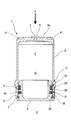
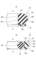
- Sectional drawing of the principal part of a piston type accumulator provided with the piston seal structure which concerns on the Example of this invention (A) The principal part expanded sectional view of the gas side seal part with which the piston seal structure is equipped, (B) is the principal part expanded sectional view of the oil side seal part with which the piston seal structure is equipped.
- FIG. 1 shows a piston type accumulator 1 including a piston seal structure 11 according to an embodiment of the present invention.
- This piston type accumulator 1 is constructed by assembling a piston 3 inside a bottomed cylindrical cylinder (shell) 2 so as to be displaceable in an axial direction (center axial direction, vertical direction in the figure).
- 2 is a gas chamber 4 that encloses a gas (nitrogen gas or the like) G, and the opposite side across the piston 3 is the oil O side of the pressure piping system.
- the piston 3 is displaced in the axial direction so that the pressure and the oil pressure are balanced.
- a gas injection port 5 is provided in the end wall portion 2a of the cylinder 2 and is closed by a gas plug 6 after the gas injection.
- a retaining ring 7 for retaining the piston 3 is mounted on the inner surface of the opening of the cylinder 2, and a screw-like connecting portion 8 for connecting the cylinder 2 to the pressure piping system is provided on the outer surface of the opening.
- a piston seal structure 11 is provided on the outer periphery of the piston 3 to seal the gas G and the oil O. That is, the gas side sealed in the gas chamber 4 does not leak to the oil O side.
- the seal portion 21 is provided, and the oil side seal portion 31 is provided so that the oil O of the pressure piping system does not enter the gas chamber 4 side.
- the gas side seal portion 21 is formed by a rubber-like elastic body such as HNBR rubber that is mounted in an annular mounting groove 9 (FIG. 1) provided on the outer peripheral surface of the piston 3.
- a backup ring 23 made of a resin material such as PTFE is arranged in parallel on the oil O side of the D ring 22.
- the D-ring 22 is formed to have a D-shaped cross section or a substantially D-shaped cross section, and has an outer circumferential surface 22a that is slidably in contact with the inner surface of the cylinder 2; Since the peripheral surface 22b and the axially opposite end faces 22c and 22d that are also linear in the cross section (plane perpendicular to the axis) are provided, the D ring 22 has a semicircular or substantially semicircular outer peripheral portion 22e and a rectangular or cross section. A substantially rectangular inner peripheral portion 22f is combined in the radial direction.
- the backup ring 23 is formed in a rectangular or substantially rectangular cross section that is long in the radial direction.
- the oil-side seal portion 31 is made of a resin material such as PTFE that is mounted in the annular mounting groove 10 (FIG. 1) provided on the outer peripheral surface of the piston 3.
- a slider seal 32 is provided, and a buckling 33 made of a rubber-like elastic body such as HNBR rubber is juxtaposed on the inner peripheral side of the slider seal 32.
- the slider seal 32 includes an outer peripheral surface 32a slidably contacting the inner surface of the cylinder 2, an inner peripheral surface 32b having a linear cross section (cylindrical surface), and both axial ends having a straight cross section (plane perpendicular to the axis). And surfaces 32c and 32d.
- the outer peripheral surface 32a has an asymmetrical shape in the piston displacement direction (axial direction, vertical direction in the figure), whereby the slider seal 32 has a pressure gradient (surface pressure gradient) to the contact surface pressure against the inner surface of the cylinder 2. Is set.
- the above-mentioned asymmetric shape is specifically configured as follows.
- the outer peripheral surface 32a of the slider seal 32 is provided with a tapered surface-shaped large-diameter cylindrical portion 32e whose outer diameter dimension gradually increases from the gas G side to the oil O side, and this large-diameter cylindrical portion 32e.
- a small-diameter cylindrical portion 32g is provided on the oil O side via a step portion 32f.
- the large-diameter cylindrical portion 32e is set to have a large outer diameter in comparison with the small-diameter cylindrical portion 32g.
- the small-diameter cylindrical portion 32g is set to have a small outer-diameter in comparison with the large-diameter cylindrical portion 32e. It is what. Therefore, with such a shape, the oil O side end portion of the large-diameter cylindrical portion 32e is a portion having the maximum outer diameter dimension, and is set so that the above-described peak value of the pressure gradient stands here.
- the buckling 33 made of a rubber-like elastic body is disposed in a compressed state between the inner peripheral surface 32b of the slider seal 32 and the bottom surface of the mounting groove 10 on the inner peripheral side of the slider seal 32. It is supported from the inner peripheral side and pressed against the inner surface of the cylinder 2.
- the cross-sectional shape of the back ring 33 is circular or substantially circular due to the relationship of the filling rate with respect to the mounting groove 10 or the like, but may be other shapes such as a rectangular or substantially rectangular shape depending on conditions.
- the D-ring 22 is mounted in the mounting groove 9 as the gas-side seal portion 21, and the D-ring 22 has a thickness of the inner peripheral portion 22f (compared with the O-ring 58 having a substantially circular cross section). Since the axial width is large, the permeation distance through which the gas G permeates can be set large to make it difficult for the gas G to permeate. Therefore, the gas impermeability can be improved and the sealing performance against the gas G can be maintained and improved.
- the D ring 22 has a large contact area with respect to the inner surface of the groove in the mounting groove 9, so that it does not easily fall over and twist. Therefore, the sealing performance against the gas G can be maintained and improved even under a situation where brittleness due to low temperature is concerned.
- the resin slider seal 32 is less likely to deteriorate in terms of material when it comes into contact with the oil O as compared with the rubber-like elastic D-ring 22. Accordingly, since the slider O seals the oil O so that the oil O does not contact the D-ring 22, the rubber-like elastic D-ring 22 is prevented from coming into contact with the oil O and deteriorating in material. be able to.
- the backup ring 23 is arranged in parallel on the oil O side of the D ring 22 in the gas side seal portion 21, it is possible to suppress the D ring 22 from protruding into the gap between the piston 3 and the cylinder 2 and being damaged. Can do.
- the slider seal 32 in the oil-side seal portion 31 includes an outer peripheral surface 32a having an asymmetric shape in the piston displacement direction, so that a pressure gradient is set in the contact surface pressure against the inner surface of the cylinder 2, so that the inner surface of the cylinder 2 A local peak value can be set for the contact surface pressure with respect to. Therefore, the sealing performance against the oil O can be improved as compared with the case where such a peak value does not exist.
- a large-diameter cylindrical portion 32e having a tapered surface shape whose outer diameter gradually increases from the gas G side to the oil O side on the outer peripheral surface 32a of the slider seal 32. Since the small-diameter cylindrical portion 32g is provided on the oil O side of the large-diameter cylindrical portion 32e via the step portion 32f, the following scraper action is caused by such a shape and a pressure gradient based thereon. Is demonstrated.
- the accumulator 1 is attached to the outer end surface of the bottom surface portion 2a of the cylinder 2 by a mounting jig (not shown) when the accumulator 1 is mounted at the mounting position. Since the mounting recess 41 for holding 1 is provided, the mounting jig is engaged with the mounting recess 41 and the accumulator 1 is held by the mounting jig, so that the mounting operation is smoothly and quickly performed. It is possible to do it.
- each recessed part 41 is provided in the outer peripheral edge part in the outer side end surface of the bottom face part 2a of the cylinder 2, it opens not only to one side of the axial direction of the cylinder 2, but to the radial direction outward of the cylinder 2.
- the mounting concave portion 41 may have a structure in which the mounting convex portion is provided by enlarging the forming angle to form a relative convex portion.
- FIG. 4 and 5 show an example in which the mounting convex portion 42 is provided in this manner, that is, when the accumulator 1 is mounted on the mounting portion on the outer end surface of the bottom surface portion 2a of the cylinder 2 (FIG. 4).
- a mounting convex portion 42 for holding the accumulator 1 is provided.
- each convex part 42 is provided in the outer periphery part in the outer side end surface of the bottom face part 2a of the cylinder 2, it has the surface toward the radial direction outward of the cylinder 2 as well as one side of the cylinder 2 in the axial direction. Yes.
- the weight of the cylinder 2 is reduced because the cutting volume at the time of formation is larger than the structure in which the mounting concave portion 41 is provided (the cylinder 2 is lighter). Can be).
- the mounting convex portion 42 may be formed by forging instead of cutting.
Landscapes
- Engineering & Computer Science (AREA)
- General Engineering & Computer Science (AREA)
- Mechanical Engineering (AREA)
- Sealing Devices (AREA)
- Supply Devices, Intensifiers, Converters, And Telemotors (AREA)
Abstract
ピストン型アキュムレータに設けられるピストンシール構造において、ガスの透過やシールの捩れまたは材質上の劣化によりシール性が低下するのを抑制する。この目的を達成するため、シリンダ内部でピストンが変位するピストン型アキュムレータに設けられるピストンシール構造であって、ピストンの外周部にガス側シール部およびオイル側シール部を並設してなるピストンシール構造において、ガス側シール部は、シリンダの内面に摺動可能に接触する断面円弧状の外周面を有するゴム状弾性体製のDリングを備える。オイル側シール部は、シリンダの内面に摺動可能に接触する外周面を有する樹脂製のスライダーシールと、スライダーシールの内周側に配置されるゴム状弾性体製のバックリングとを備える。
Description
本発明は、ピストン型アキュムレータに設けられるピストンシール構造に関する。
従来から図6に示すように、シリンダ52内部でピストン53が変位するピストン型アキュムレータ51が知られており、ピストン53の外周部には、ガス室54に封入したガスGがオイルO側へ漏れることがないようにガス側シール部55が設けられるとともに、圧力配管系を流れるオイルOがガス室54側へ侵入することがないようにオイル側シール部56が設けられている。ピストン53はガス圧およびオイル圧が均衡するようにシリンダ52内部で軸方向(中心軸線方向、図では左右方向)に変位する。
ガス側シール部55およびオイル側シール部56はそれぞれ、ピストン53の外周面に設けた装着溝57に装着されるゴム状弾性体製のOリング58によって構成されている。
しかしながら、ゴム状弾性体製のOリング58はその断面形状が円形ないし略円形とされているため、ガスGがこのOリング58を透過する透過距離を特にリング内周部において大きく設定することができない。したがってガスGがOリング58を透過することがあり、このガスGの透過が漏れにつながる不都合がある。
また、ゴム状弾性体製のOリング58は、装着溝57内で捩れた状態となりやすい。したがってOリング58が捩れた状態となることで、漏れにつながる不都合がある。
更にまた、ゴム状弾性体製のOリング58は、オイルOと接触することにより材質上劣化することがある。したがってこのようにOリング58が材質上劣化することで、漏れにつながる不都合もある。
本発明は以上の点に鑑みて、ピストン型アキュムレータに設けられるピストンシール構造において、ガスの透過やシールの捩れまたは材質上の劣化によりシール性が低下するのを抑制することができるピストンシール構造を提供することを目的とする。
上記目的を達成するため、本発明の請求項1によるピストンシール構造は、シリンダ内部でピストンが変位するピストン型アキュムレータに設けられるピストンシール構造であって、前記ピストンの外周部にガス側シール部およびオイル側シール部を並設してなるピストンシール構造において、前記ガス側シール部は、前記シリンダの内面に摺動可能に接触する断面円弧状の外周面を有するゴム状弾性体製のDリングを備え、前記オイル側シール部は、前記シリンダの内面に摺動可能に接触する外周面を有する樹脂製のスライダーシールと、前記スライダーシールの内周側に配置されるゴム状弾性体製のバックリングとを備えることを特徴とする。
また、本発明の請求項2によるピストンシール構造は、上記した請求項1記載のピストンシール構造において、前記ガス側シール部は、前記Dリングのオイル側に配置されるバックアップリングを備えることを特徴とする。
また、本発明の請求項3によるピストンシール構造は、上記した請求項1または2記載のピストンシール構造において、前記ガス側シール部における前記スライダーシールは、ピストン変位方向に非対称な形状の外周面を備えることにより前記シリンダの内面に対する接触面圧に圧力勾配を設定することを特徴とする。
上記構成を備える本発明のピストンシール構造は、ガス側シール部としてゴム状弾性体製のDリングを備えるとともに、オイル側シール部として樹脂製のスライダーシールおよびゴム状弾性体製のバックリングよりなる組合せシールを備えることを特徴とする。
ゴム状弾性体製のDリングはその名のとおり、断面形状がD形ないし略D形とされており、シリンダの内面に摺動可能に接触する外周面は断面円弧状ないし略円弧形とされているが、内周部は断面長方形ないし略長方形とされている。したがって断面円形ないし略円形のOリングと比較してリング内周部の厚み(軸方向幅)が大きいため、この分、ガスが透過する透過距離を大きく設定することができ、ガスが透過しにくくなる。またこのDリングによれば、低温脆性化でのシール倒れ防止についても効果を発揮することができ、すなわちOリングは装着溝内で捩れやすいのに対し、Dリングは装着溝内で倒れにくく捩れにくい。したがって低温時などにおけるガスシール性が低下するのを抑制することが可能とされる。
また、樹脂製のスライダーシールは、ゴム状弾性体製のDリングと比較してオイルと接触したときに材質上劣化しにくい。したがってこのスライダーシールがオイルをシールすることによりオイルがDリングに接触しなくなるため、ゴム状弾性体製のDリングがオイルと接触して材質上劣化してしまうのを抑制することが可能とされる。
また、ガス側シール部においては、Dリングがピストンおよびシリンダ間の隙間へはみ出すことにより損傷するおそれがあるが、これに対してはDリングのオイル側にバックアップリングを配置し、このバックアップリングによってDリングを支持することにより、はみ出しを抑制することが考えられる。このほかバックアップリングについては、スライダーシールのガス側にバックアップリングを配置し、バックアップリングによってスライダーシールを支持するようにしても良い。
樹脂製のスライダーシールについては、ピストン変位方向に非対称な形状の外周面を備えることによりシリンダの内面に対する接触面圧に圧力勾配を設定するようにしても良く、この場合は、シリンダの内面に対する接触面圧に局所的なピーク値が設定されるため、オイルに対するシール性を向上させることが可能とされる。ここに圧力勾配(面圧勾配)は、スライダーシールの外周面にテーパーや段差などを形成することにより設定されるものである。
本発明によれば以上説明したように、ピストン型アキュムレータに設けられるピストンシール構造において、ガスの透過やシールの捩れまたは材質上の劣化によりシール性が低下するのを抑制するピストンシール構造を提供することができる。
つぎに本発明の実施例を図面にしたがって説明する。
図1は、本発明の実施例に係るピストンシール構造11を備えるピストン型アキュムレータ1を示している。このピストン型アキュムレータ1は、有底円筒状のシリンダ(シェル)2の内部にピストン3を軸方向(中心軸線方向、図では上下方向)に変位可能に組み付けたものであって、ピストン3およびシリンダ2の底面部(端壁部)2a間の空間はガス(窒素ガスなど)Gを封入するガス室4とされ、ピストン3を挟んで反対側は圧力配管系のオイルO側とされ、封入ガス圧とオイル圧とが均衡するようにピストン3が軸方向に変位する。シリンダ2の端壁部2aにはガス注入口5が設けられ、ガス注入後、ガスプラグ6によって閉塞されている。シリンダ2の開口部内面にはピストン3を抜け止めする抜け止めリング7が装着され、開口部外面には当該シリンダ2を圧力配管系へ接続するためのネジ状接続部8が設けられている。
ピストン3の外周部に、ガスGをシールするとともにオイルOをシールするためにピストンシール構造11が設けられ、すなわちガス室4に封入したガスGがオイルO側へ漏れることがないようにガス側シール部21が設けられるとともに、圧力配管系のオイルOがガス室4側へ侵入することがないようにオイル側シール部31が設けられている。
図2(A)に拡大して示すように、ガス側シール部21は、ピストン3の外周面に設けた環状の装着溝9(図1)に装着されるHNBRゴム等のゴム状弾性体よりなるDリング22を備えており、このDリング22のオイルO側にPTFE等の樹脂材料よりなるバックアップリング23が並設されている。
Dリング22はその名のとおり、断面D形ないし略D形に成形され、シリンダ2の内面に摺動可能に接触する断面円弧状の外周面22aと、断面直線状(円筒面状)の内周面22bと、同じく断面直線状(軸直角平面状)の軸方向両端面22c,22dとを備えているので、Dリング22は断面半円形ないし略半円形の外周部22eと、断面長方形ないし略長方形の内周部22fとが径方向に組み合わされた形状とされている。バックアップリング23は、径方向に長い断面長方形ないし略長方形に成形されている。
一方、図2(B)に拡大して示すように、オイル側シール部31は、ピストン3の外周面に設けた環状の装着溝10(図1)に装着されるPTFE等の樹脂材料よりなるスライダーシール32を備えており、このスライダーシール32の内周側にHNBRゴム等のゴム状弾性体よりなるバックリング33が並設されている。
スライダーシール32は、シリンダ2の内面に摺動可能に接触する外周面32aと、断面直線状(円筒面状)の内周面32bと、同じく断面直線状(軸直角平面状)の軸方向両端面32c,32dとを備えている。またこのうち外周面32aはピストン変位方向(軸方向、図では上下方向)に非対称な形状とされ、これによりスライダーシール32には、シリンダ2の内面に対する接触面圧に圧力勾配(面圧勾配)が設定されている。
上記した非対称な形状は具体的には、以下のように構成されている。
すなわち、スライダーシール32の外周面32aにガスG側からオイルO側へかけてその外径寸法が徐々に拡大するテーパー面状の大径筒状部32eが設けられ、この大径筒状部32eのオイルO側に段差部32fを介して小径筒状部32gが設けられている。大径筒状部32eは小径筒状部32gとの比較において外径寸法が大きく設定され、反対に小径筒状部32gは大径筒状部32eとの比較において外径寸法が小さく設定されているものである。したがってこのような形状により、大径筒状部32eのオイルO側端部が最大外径寸法を備える部位とされ、ここに上記した圧力勾配のピーク値が立つように設定されている。
ゴム状弾性体よりなるバックリング33は、スライダーシール32の内周側であってスライダーシール32の内周面32bおよび装着溝10の底面間に圧縮された状態で配置され、スライダーシール32をその内周側から支持してシリンダ2の内面に押し付ける。バックリング33の断面形状は、装着溝10に対する充填率の関係などからして円形ないし略円形とされているが、条件によってはその他の形状、例えば断面長方形ないし略長方形などであっても良い。
上記構成を備えるピストンシール構造11においては、ガス側シール部21として装着溝9にDリング22が装着され、Dリング22は断面略円形のOリング58と比較して内周部22fの厚み(軸方向幅)が大きいため、ガスGが透過する透過距離を大きく設定し、ガスGを透過させにくくすることができる。したがってガス不透過性を向上させ、ガスGに対するシール性を維持・向上させることができる。
また、Dリング22は装着溝9内で溝内面に対する接触面積が大きいために倒れにくく捩れにくいものである。したがって低温による脆性化が懸念される状況下であってもガスGに対するシール性を維持・向上させることができる。
また、樹脂製のスライダーシール32は、ゴム状弾性体製のDリング22と比較してオイルOと接触したときに材質上劣化しにくいものである。したがってこのスライダーシール32がオイルOをシールすることによりオイルOがDリング22に接触しないため、ゴム状弾性体製のDリング22がオイルOと接触して材質上劣化してしまうのを抑制することができる。
また、ガス側シール部21において、Dリング22のオイルO側にバックアップリング23が並設されているため、Dリング22がピストン3およびシリンダ2間の隙間へはみ出して損傷するのを抑制することができる。
また、オイル側シール部31におけるスライダーシール32がピストン変位方向に非対称な形状の外周面32aを備え、これによりシリンダ2の内面に対する接触面圧に圧力勾配が設定されているため、シリンダ2の内面に対する接触面圧に局所的なピーク値を設定することができる。したがってこのようなピーク値が存在しない場合と比較して、オイルOに対するシール性を向上させることができる。
更にまた、上記非対称な形状の具体的形状として、スライダーシール32の外周面32aにガスG側からオイルO側へかけて外径寸法が徐々に拡大するテーパー面状の大径筒状部32eが設けられ、この大径筒状部32eのオイルO側に段差部32fを介して小径筒状部32gが設けられているため、このような形状およびこれにもとづく圧力勾配によって以下のようなスクレーパー作用が発揮される。
すなわち、ピストン3がオイルO側からガスG側へ変位するときシリンダ2の内面に油膜が形成されるのに対し、反対にピストン3がガスG側からオイルO側へ変位するときにスライダーシール32がその大径筒状部32eの最大外径寸法部位をもって油膜を掻き取り回収する。したがってここにスライダーシール32によるスクレーパー作用が発揮されるため、これによりオイルOに対するシール性を向上させることができる。
上記実施例に係るアキュムレータ1において、シリンダ2の底面部2aの外側端面には図1に示したように、当該アキュムレータ1を装着箇所に装着するときに装着治具(図示せず)によって当該アキュムレータ1を保持するための装着用凹部41が設けられているので、この装着用凹部41に装着治具を係合し、装着治具によって当該アキュムレータ1を保持することにより、装着作業を円滑・迅速に行うことが可能とされている。
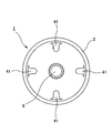
装着用凹部41は、図3に示すように、シリンダ2の底面部2aの外側端面における外周部に複数(図では4箇所)が等配状に設けられている。各凹部41はシリンダ2の底面部2aの外側端面における外周縁部に設けられているので、シリンダ2の軸方向一方のみならずシリンダ2の径方向外方へ向けても開口している。
また、この装着用凹部41については、その形成角度を拡大して相対の凸部を形成することにより、装着用凸部を設ける構造としても良い。
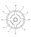
図4および図5はこのようにして装着用凸部42を設けた例を示し、すなわちシリンダ2の底面部2aの外側端面に、当該アキュムレータ1を装着箇所に装着するときに装着治具(図示せず)によって当該アキュムレータ1を保持するための装着用凸部42が設けられている。
装着用凸部42は、図5に示すように、シリンダ2の底面部2aの外側端面における外周部に複数(図では4箇所)が等配状に設けられている。各凸部42はシリンダ2の底面部2aの外側端面における外周縁部に設けられているので、シリンダ2の軸方向一方のみならずシリンダ2の径方向外方へ向けての面を有している。
そして、このように装着用凸部42を設ける構造によれば、装着用凹部41を設ける構造と比較して、形成時の切削体積が多いため、シリンダ2の重量を削減する(シリンダ2を軽量化する)ことができる。尚、装着用凸部42はこれを切削加工でなく鍛造成形で形成しても良い。
1 アキュムレータ
2 シリンダ
2a 底面部
3 ピストン
4 ガス室
5 ガス注入口
6 ガスプラグ
7 抜け止めリング
8 接続部
9,10 装着溝
11 ピストンシール構造
21 ガス側シール部
22 Dリング
22a,32a 外周面
22b,32b 内周面
22c,22d,32c,32d 端面
22e 外周部
22f 内周部
23 バックアップリング
31 オイル側シール部
32 スライダーシール
32e 大径筒状部
32f 段差部
32g 小径筒状部
33 バックリング
41 装着用凹部
42 装着用凸部
G ガス
O オイル
2 シリンダ
2a 底面部
3 ピストン
4 ガス室
5 ガス注入口
6 ガスプラグ
7 抜け止めリング
8 接続部
9,10 装着溝
11 ピストンシール構造
21 ガス側シール部
22 Dリング
22a,32a 外周面
22b,32b 内周面
22c,22d,32c,32d 端面
22e 外周部
22f 内周部
23 バックアップリング
31 オイル側シール部
32 スライダーシール
32e 大径筒状部
32f 段差部
32g 小径筒状部
33 バックリング
41 装着用凹部
42 装着用凸部
G ガス
O オイル
Claims (3)
- シリンダ内部でピストンが変位するピストン型アキュムレータに設けられるピストンシール構造であって、前記ピストンの外周部にガス側シール部およびオイル側シール部を並設してなるピストンシール構造において、
前記ガス側シール部は、前記シリンダの内面に摺動可能に接触する断面円弧状の外周面を有するゴム状弾性体製のDリングを備え、
前記オイル側シール部は、前記シリンダの内面に摺動可能に接触する外周面を有する樹脂製のスライダーシールと、前記スライダーシールの内周側に配置されるゴム状弾性体製のバックリングとを備えることを特徴とするピストン型アキュムレータのピストンシール構造。 - 請求項1記載のピストンシール構造において、
前記ガス側シール部は、前記Dリングのオイル側に配置されるバックアップリングを備えることを特徴とするピストン型アキュムレータのピストンシール構造。 - 請求項1または2記載のピストンシール構造において、
前記ガス側シール部における前記スライダーシールは、ピストン変位方向に非対称な形状の外周面を備えることにより前記シリンダの内面に対する接触面圧に圧力勾配を設定することを特徴とするピストン型アキュムレータのピストンシール構造。
Priority Applications (1)
| Application Number | Priority Date | Filing Date | Title |
|---|---|---|---|
| JP2017517368A JP6748073B2 (ja) | 2015-09-30 | 2016-09-07 | ピストン型アキュムレータのピストンシール構造 |
Applications Claiming Priority (2)
| Application Number | Priority Date | Filing Date | Title |
|---|---|---|---|
| JP2015193605 | 2015-09-30 | ||
| JP2015-193605 | 2015-09-30 |
Publications (1)
| Publication Number | Publication Date |
|---|---|
| WO2017056884A1 true WO2017056884A1 (ja) | 2017-04-06 |
Family
ID=58423319
Family Applications (1)
| Application Number | Title | Priority Date | Filing Date |
|---|---|---|---|
| PCT/JP2016/076247 Ceased WO2017056884A1 (ja) | 2015-09-30 | 2016-09-07 | ピストン型アキュムレータのピストンシール構造 |
Country Status (2)
| Country | Link |
|---|---|
| JP (1) | JP6748073B2 (ja) |
| WO (1) | WO2017056884A1 (ja) |
Cited By (2)
| Publication number | Priority date | Publication date | Assignee | Title |
|---|---|---|---|---|
| CN111212995A (zh) * | 2018-05-30 | 2020-05-29 | Nok株式会社 | 密封环和密封结构 |
| CN115163583A (zh) * | 2022-06-28 | 2022-10-11 | 杰锋汽车动力系统股份有限公司 | 一种提高密封性的蓄能器结构 |
Citations (2)
| Publication number | Priority date | Publication date | Assignee | Title |
|---|---|---|---|---|
| JPH04109258U (ja) * | 1991-03-08 | 1992-09-22 | 株式会社小松製作所 | アキユムレータ用ピストン |
| JP2006316947A (ja) * | 2005-05-16 | 2006-11-24 | Mitsubishi Cable Ind Ltd | 塗装機用ピストンパッキン |
-
2016
- 2016-09-07 JP JP2017517368A patent/JP6748073B2/ja active Active
- 2016-09-07 WO PCT/JP2016/076247 patent/WO2017056884A1/ja not_active Ceased
Patent Citations (2)
| Publication number | Priority date | Publication date | Assignee | Title |
|---|---|---|---|---|
| JPH04109258U (ja) * | 1991-03-08 | 1992-09-22 | 株式会社小松製作所 | アキユムレータ用ピストン |
| JP2006316947A (ja) * | 2005-05-16 | 2006-11-24 | Mitsubishi Cable Ind Ltd | 塗装機用ピストンパッキン |
Cited By (2)
| Publication number | Priority date | Publication date | Assignee | Title |
|---|---|---|---|---|
| CN111212995A (zh) * | 2018-05-30 | 2020-05-29 | Nok株式会社 | 密封环和密封结构 |
| CN115163583A (zh) * | 2022-06-28 | 2022-10-11 | 杰锋汽车动力系统股份有限公司 | 一种提高密封性的蓄能器结构 |
Also Published As
| Publication number | Publication date |
|---|---|
| JPWO2017056884A1 (ja) | 2018-07-19 |
| JP6748073B2 (ja) | 2020-08-26 |
Similar Documents
| Publication | Publication Date | Title |
|---|---|---|
| US10612660B2 (en) | Gasket | |
| KR102143056B1 (ko) | 오일 시일 | |
| JP6029700B2 (ja) | 回転するシャフト用のダブルシール装置及び該ダブルシール装置を備えるポンプ | |
| KR101819782B1 (ko) | 스프링 활성 순부를 구비한 유관 변환기 | |
| JP6748200B2 (ja) | シール構造 | |
| US9915315B2 (en) | Production of multi-part, joined valve components in hydraulic applications with joint sealing profiles | |
| JP6830480B2 (ja) | 改善された管状ねじ部材の圧力試験プラグ | |
| JP6447667B2 (ja) | シールリング及び密封構造 | |
| WO2017056884A1 (ja) | ピストン型アキュムレータのピストンシール構造 | |
| KR101983482B1 (ko) | 완충기 | |
| AU2020202496B2 (en) | Annular sealing assembly | |
| JPWO2006070568A1 (ja) | 密封装置 | |
| KR102414544B1 (ko) | 가압실 측면에 도포된 막을 갖는 압력 센서 및 그러한 압력 센서의 용도 | |
| JP4853633B2 (ja) | 密封装置 | |
| JP6450910B2 (ja) | 溶接ハイブリッドリングを備えるシリンダヘッドガスケット | |
| JP2018151002A5 (ja) | ||
| JP5116153B2 (ja) | ベローズ式アキュムレータ | |
| JP6869105B2 (ja) | ガスケット及び密封構造 | |
| JP2015183749A (ja) | 回転軸シール | |
| JP6675169B2 (ja) | 圧力容器の密封構造 | |
| CN109323001A (zh) | 密封装置 | |
| WO2018056099A1 (ja) | 緩衝器 | |
| WO2017086012A1 (ja) | バンプストッパ、及び緩衝器 | |
| TWI606201B (zh) | Sealing member | |
| JP6899037B2 (ja) | 密封装置 |
Legal Events
| Date | Code | Title | Description |
|---|---|---|---|
| ENP | Entry into the national phase |
Ref document number: 2017517368 Country of ref document: JP Kind code of ref document: A |
|
| 121 | Ep: the epo has been informed by wipo that ep was designated in this application |
Ref document number: 16851058 Country of ref document: EP Kind code of ref document: A1 |
|
| NENP | Non-entry into the national phase |
Ref country code: DE |
|
| 122 | Ep: pct application non-entry in european phase |
Ref document number: 16851058 Country of ref document: EP Kind code of ref document: A1 |