WO2017056883A1 - 吸気制御装置 - Google Patents
吸気制御装置 Download PDFInfo
- Publication number
- WO2017056883A1 WO2017056883A1 PCT/JP2016/076240 JP2016076240W WO2017056883A1 WO 2017056883 A1 WO2017056883 A1 WO 2017056883A1 JP 2016076240 W JP2016076240 W JP 2016076240W WO 2017056883 A1 WO2017056883 A1 WO 2017056883A1
- Authority
- WO
- WIPO (PCT)
- Prior art keywords
- valve
- throttle valve
- shaft portion
- axial direction
- location
- Prior art date
- Legal status (The legal status is an assumption and is not a legal conclusion. Google has not performed a legal analysis and makes no representation as to the accuracy of the status listed.)
- Ceased
Links
Images





Classifications
-
- F—MECHANICAL ENGINEERING; LIGHTING; HEATING; WEAPONS; BLASTING
- F02—COMBUSTION ENGINES; HOT-GAS OR COMBUSTION-PRODUCT ENGINE PLANTS
- F02D—CONTROLLING COMBUSTION ENGINES
- F02D9/00—Controlling engines by throttling air or fuel-and-air induction conduits or exhaust conduits
- F02D9/08—Throttle valves specially adapted therefor; Arrangements of such valves in conduits
- F02D9/10—Throttle valves specially adapted therefor; Arrangements of such valves in conduits having pivotally-mounted flaps
- F02D9/1065—Mechanical control linkage between an actuator and the flap, e.g. including levers, gears, springs, clutches, limit stops of the like
-
- F—MECHANICAL ENGINEERING; LIGHTING; HEATING; WEAPONS; BLASTING
- F02—COMBUSTION ENGINES; HOT-GAS OR COMBUSTION-PRODUCT ENGINE PLANTS
- F02D—CONTROLLING COMBUSTION ENGINES
- F02D9/00—Controlling engines by throttling air or fuel-and-air induction conduits or exhaust conduits
- F02D9/08—Throttle valves specially adapted therefor; Arrangements of such valves in conduits
- F02D9/10—Throttle valves specially adapted therefor; Arrangements of such valves in conduits having pivotally-mounted flaps
- F02D9/107—Manufacturing or mounting details
-
- F—MECHANICAL ENGINEERING; LIGHTING; HEATING; WEAPONS; BLASTING
- F02—COMBUSTION ENGINES; HOT-GAS OR COMBUSTION-PRODUCT ENGINE PLANTS
- F02D—CONTROLLING COMBUSTION ENGINES
- F02D41/00—Electrical control of supply of combustible mixture or its constituents
- F02D41/0002—Controlling intake air
-
- F—MECHANICAL ENGINEERING; LIGHTING; HEATING; WEAPONS; BLASTING
- F02—COMBUSTION ENGINES; HOT-GAS OR COMBUSTION-PRODUCT ENGINE PLANTS
- F02D—CONTROLLING COMBUSTION ENGINES
- F02D9/00—Controlling engines by throttling air or fuel-and-air induction conduits or exhaust conduits
- F02D9/08—Throttle valves specially adapted therefor; Arrangements of such valves in conduits
- F02D9/10—Throttle valves specially adapted therefor; Arrangements of such valves in conduits having pivotally-mounted flaps
-
- F—MECHANICAL ENGINEERING; LIGHTING; HEATING; WEAPONS; BLASTING
- F02—COMBUSTION ENGINES; HOT-GAS OR COMBUSTION-PRODUCT ENGINE PLANTS
- F02D—CONTROLLING COMBUSTION ENGINES
- F02D9/00—Controlling engines by throttling air or fuel-and-air induction conduits or exhaust conduits
- F02D9/08—Throttle valves specially adapted therefor; Arrangements of such valves in conduits
- F02D9/10—Throttle valves specially adapted therefor; Arrangements of such valves in conduits having pivotally-mounted flaps
- F02D9/1005—Details of the flap
-
- F—MECHANICAL ENGINEERING; LIGHTING; HEATING; WEAPONS; BLASTING
- F02—COMBUSTION ENGINES; HOT-GAS OR COMBUSTION-PRODUCT ENGINE PLANTS
- F02D—CONTROLLING COMBUSTION ENGINES
- F02D9/00—Controlling engines by throttling air or fuel-and-air induction conduits or exhaust conduits
- F02D9/08—Throttle valves specially adapted therefor; Arrangements of such valves in conduits
- F02D9/10—Throttle valves specially adapted therefor; Arrangements of such valves in conduits having pivotally-mounted flaps
- F02D9/1035—Details of the valve housing
- F02D9/106—Sealing of the valve shaft in the housing, e.g. details of the bearings
-
- F—MECHANICAL ENGINEERING; LIGHTING; HEATING; WEAPONS; BLASTING
- F16—ENGINEERING ELEMENTS AND UNITS; GENERAL MEASURES FOR PRODUCING AND MAINTAINING EFFECTIVE FUNCTIONING OF MACHINES OR INSTALLATIONS; THERMAL INSULATION IN GENERAL
- F16K—VALVES; TAPS; COCKS; ACTUATING-FLOATS; DEVICES FOR VENTING OR AERATING
- F16K1/00—Lift valves or globe valves, i.e. cut-off apparatus with closure members having at least a component of their opening and closing motion perpendicular to the closing faces
- F16K1/16—Lift valves or globe valves, i.e. cut-off apparatus with closure members having at least a component of their opening and closing motion perpendicular to the closing faces with pivoted closure-members
- F16K1/18—Lift valves or globe valves, i.e. cut-off apparatus with closure members having at least a component of their opening and closing motion perpendicular to the closing faces with pivoted closure-members with pivoted discs or flaps
- F16K1/22—Lift valves or globe valves, i.e. cut-off apparatus with closure members having at least a component of their opening and closing motion perpendicular to the closing faces with pivoted closure-members with pivoted discs or flaps with axis of rotation crossing the valve member, e.g. butterfly valves
- F16K1/224—Details of bearings for the axis of rotation
-
- Y—GENERAL TAGGING OF NEW TECHNOLOGICAL DEVELOPMENTS; GENERAL TAGGING OF CROSS-SECTIONAL TECHNOLOGIES SPANNING OVER SEVERAL SECTIONS OF THE IPC; TECHNICAL SUBJECTS COVERED BY FORMER USPC CROSS-REFERENCE ART COLLECTIONS [XRACs] AND DIGESTS
- Y02—TECHNOLOGIES OR APPLICATIONS FOR MITIGATION OR ADAPTATION AGAINST CLIMATE CHANGE
- Y02T—CLIMATE CHANGE MITIGATION TECHNOLOGIES RELATED TO TRANSPORTATION
- Y02T10/00—Road transport of goods or passengers
- Y02T10/10—Internal combustion engine [ICE] based vehicles
- Y02T10/40—Engine management systems
Definitions
- the present disclosure relates to an intake control device that controls the flow of intake air in an intake passage of an internal combustion engine.
- an intake control device that opens and closes an intake passage by rotation of a throttle valve housed in an intake passage formed by a valve body has been widely applied to internal combustion engines.
- the valve shaft is fastened to the throttle valve at two axial positions by a pair of fastening members.
- the rotation shaft portion of the valve shaft that protrudes to both sides in the axial direction from the throttle valve is pivotally supported by each of separate bearings held by the valve body.
- the 1st bearing which pivotally supports the one side rotation shaft part has an inner ring fixed to the one side rotation shaft part, and an outer ring fixed to the valve body.
- the second bearing that pivotally supports the other rotation shaft portion includes an inner ring that is slidably fitted in the axial direction with respect to the other rotation shaft portion, and an outer ring that is fixed to the valve body.
- an aluminum-based material is used as a material for a valve body and a throttle valve, while an iron-based material is used as a material for a valve shaft.
- the linear expansion coefficients of the throttle valve and the valve body are larger than the linear expansion coefficient of the valve shaft in the axial direction.
- the valve shaft that can slide in the axial direction on the second bearing side opposite to the first bearing fixed to the inner ring undergoes relative displacement due to the difference in thermal expansion coefficient with respect to the valve body. become. Therefore, a recess for releasing the relative displacement at least around the shaft portion on the second bearing side of the valve shaft is provided in the axial edge portion of the throttle valve. As a result, even if relative displacement of the valve shaft occurs, it is possible to suppress the interference between the throttle valve and the valve body and to secure the characteristics as the intake control device.
- the present disclosure has been made in view of the above-described problems, and an object thereof is to ensure characteristics as an intake air control device.
- An intake control device for controlling the flow of intake air in an intake passage of an internal combustion engine, A throttle valve that opens and closes the intake passage by rotation; A first rotation shaft portion and a second rotation shaft portion that protrude toward the one side and the other side in the axial direction from the throttle valve, respectively, and a space between the first rotation shaft portion and the second rotation shaft portion in the axial direction.
- a valve shaft having a fastening shaft portion connected and fastened to the throttle valve so as to be integrally rotatable;
- a first fastening member that fastens the fastening shaft portion to the throttle valve at a first location that is located closer to the first rotation shaft portion than the center point of the throttle valve in the axial direction;
- a second fastening member for fastening the fastening shaft portion to the throttle valve at a second location located on the second rotating shaft portion side from the center point;
- a valve body forming an intake passage for accommodating the throttle valve;
- a first bearing that is held by the valve body and pivotally supports the first rotating shaft portion;
- a second bearing that is held by the valve body and pivotally supports the second rotation shaft portion,
- the first bearing has an inner ring fixed to the first rotation shaft portion, and an outer ring fixed to the valve body,
- the second bearing has a sliding portion that is slidably fitted in the axial direction with respect to the second rotating shaft portion, and a fixed portion that is fixed to the valve body,
- the linear expansion coefficients of the throttle valve and the valve body in the axial direction are set larger than the linear expansion coefficient of the valve shaft. Therefore, in order to suppress the interference between the throttle valve and the valve body, the thermal deformation amount difference according to the linear expansion coefficient difference between the throttle valve and the valve shaft and the linear expansion coefficient difference between the valve body and the valve shaft are used. It is necessary to consider the difference in thermal deformation amount.
- the first rotation shaft portion of the first bearing is fixed by fixing the first rotation shaft portion of the valve shaft to the inner ring of the first bearing where the outer ring is fixed to the valve body.
- the shaft support is realized. Therefore, in order to secure a fully closed clearance on the first rotating shaft side and suppress interference between the throttle valve and the valve body, a difference in thermal expansion amount between the throttle valve and the valve shaft, It is necessary to reduce the sum of the difference in thermal expansion between the body and the valve stem, which is the difference in thermal deformation, at high temperatures.
- the second rotating shaft portion of the valve shaft is slidably fitted in the axial direction to the sliding portion of the second bearing fixed to the valve body.
- the shaft support of the second rotating shaft portion by the two bearings is realized. Therefore, in order to secure a fully closed clearance on the second rotating shaft portion side and suppress interference between the throttle valve and the valve body, a difference in thermal contraction amount, which is a difference in thermal deformation amount between the throttle valve and the valve shaft, It is necessary to make it larger at a low temperature than the heat shrinkage difference, which is the difference in heat deformation between the body and the valve stem.
- the fastening shaft portion is fastened to the throttle valve by the first fastening member at the first position located on the first rotating shaft portion side with respect to the center point in the axial direction of the throttle valve.
- the fastening shaft portion of the valve shaft is fastened to the throttle valve by the second fastening member at a second position located on the second rotating shaft portion side of the center point in the axial direction of the throttle valve.
- the first distance from the central point of the throttle valve to the first location in the axial direction of the above configuration is based on the knowledge about the difference in thermal expansion amount and the thermal contraction amount described above. It is set larger than the second distance to the second location.
- the first location where the first distance from the center point becomes larger in the throttle valve is close to the axial edge on the first rotating shaft side.
- the axial distance in the range from the first location to the first rotation shaft side edge is reduced, and in this range, the difference in thermal expansion between the throttle valve and the valve shaft is reduced at high temperatures. obtain. Therefore, on the first rotating shaft side, the sum of the difference in thermal expansion between the throttle valve and the valve shaft and the difference in thermal expansion between the valve body and the valve shaft can also be reduced at high temperatures. Thus, interference between the throttle valve and the valve body can be suppressed.
- the second portion where the second distance from the center point becomes small in the throttle valve is separated from the axial edge on the second rotating shaft side.
- the axial distance in the range from the second location to the second rotating shaft side edge increases, and in this range, the heat shrinkage difference between the throttle valve and the valve shaft is expanded at low temperatures. obtain. Therefore, on the second rotating shaft side, the fully closed clearance is secured by making the heat shrinkage difference between the throttle valve and the valve shaft larger at the low temperature than the heat shrinkage difference between the valve body and the valve shaft.
- the intake air is inhaled when the throttle valve is fully closed, exceeding the unavoidable flow rate from the fully closed clearance secured to suppress interference between the throttle valve and the valve body. It is also possible to avoid the situation of circulating through the passage. Therefore, the characteristics as the intake control device can be ensured.
- the linear expansion coefficient of the throttle valve may be set larger than the linear expansion coefficient of the valve body.
- the linear expansion coefficient of the throttle valve is set to be larger than the linear expansion coefficient of the valve body, so that the difference in thermal expansion between the throttle valve and the valve shaft is the difference between the valve body and the valve shaft. It tends to be larger than the difference in thermal expansion.
- the axial distance decreases according to the setting of the first and second distances described above, so the distance between the throttle valve and the valve shaft The difference in the amount of thermal expansion at a high temperature can be reduced as much as possible.
- the difference between the thermal expansion amount between the valve body and the valve shaft and the difference between the thermal expansion amounts between the throttle valve and the valve shaft, which are likely to be larger, are summed up. It is possible to reduce the interference at a high temperature to suppress the interference between the throttle valve and the valve body.
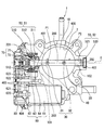
- the intake control device 1 As shown in FIGS. 1 to 3, the intake control device 1 according to the first embodiment is mounted on an internal combustion engine of a vehicle.
- the intake control device 1 controls the flow of intake air in the passage 2 by opening and closing the intake passage 2 of the internal combustion engine.
- the intake control device 1 includes a throttle valve 10, a valve shaft 20, a fastening structure 30, a valve body 40, a bearing structure 50, a drive unit 60, a sensor unit 70, and a cover member 80.
- the throttle valve 10 is a butterfly type rotary valve, and is formed in a circular plate shape from a metal material.
- the throttle valve 10 is accommodated in the intake passage 2 so as to be rotatable.
- the throttle valve 10 opens and closes the intake passage 2 by turning around the axis O.
- the flow rate of intake air in the intake passage 2 is controlled by adjusting the opening degree (opening area) of the intake passage 2 by the valve 10 according to the rotational position of the throttle valve 10.
- the valve shaft 20 is a shaft for rotating the throttle valve 10, and is formed into a long and thin round bar shape from a metal material.
- the valve shaft 20 is disposed along an axis O that substantially coincides with the center line of the valve shaft 20, and crosses the intake passage 2.
- the valve shaft 20 has a fastening shaft portion 200 and rotating shaft portions 201 and 202.
- the fastening shaft portion 200 is a portion exposed to the intake passage 2 in the valve shaft 20.
- the fastening shaft portion 200 is provided with a fitting hole 203 penetrating in the radial direction.
- the throttle valve 10 is fastened to the fastening shaft portion 200 so as to be integrally rotatable in a state of being inserted and fitted in the fitting hole 203 in the radial direction.
- the rotation shaft portions 201 and 202 are connected in the axial direction by the fastening shaft portion 200.
- the axial direction and radial direction of the valve shaft 20 are simply referred to as “axial direction” and “radial direction”.
- the first rotating shaft portion 201 extends from the fastening shaft portion 200 to one side in the axial direction.
- the first rotating shaft portion 201 is disposed outside the intake passage 2 by projecting to the one side in the axial direction from the throttle valve 10 by such an extended form.
- the second rotation shaft portion 202 extends from the fastening shaft portion 200 to the other side in the axial direction.
- the second rotation shaft portion 202 is disposed outside the intake passage 2 by projecting to the other side in the axial direction from the throttle valve 10 by such an extended form.
- the fastening structure 30 is composed of a pair of fastening members 31 and 32.
- the fastening members 31 and 32 are screw members that cooperate with each other to fasten the fastening shaft portion 200 to the throttle valve 10, and are each formed in a male screw shape from a metal material.
- the fastening members 31 and 32 have substantially the same shape and size in the present embodiment, but may have different shapes and sizes.
- the first fastening member 31 is provided corresponding to the first location P1 in the axial direction of the fastening shaft portion 200.
- the first fastening member 31 at the first location P1 is screwed to the fastening shaft portion 200 in a state of passing through the fastening shaft portion 200 and the throttle valve 10 in a radial direction perpendicular to the penetration direction of the fitting hole 203. .
- the 1st fastening member 31 has implement
- the second fastening member 32 is provided corresponding to the second location P2 in the axial direction of the fastening shaft portion 200.
- the second fastening member 32 is screwed to the fastening shaft portion 200 in a state of passing through the fastening shaft portion 200 and the throttle valve 10 in the radial direction orthogonal to the penetration direction of the fitting hole 203. .
- the 2nd fastening member 32 has implement
- the valve body 40 is a fixed node fixed to the internal combustion engine in order to form the intake passage 2 and is formed in a hollow shape from a metal material.
- the valve body 40 has a bore 400 that forms the intake passage 2 and accommodates the throttle valve in a cylindrical hole shape.
- the bore portion 400 can close the intake passage 2 by fitting in the entire outer peripheral portion of the throttle valve 10 rotated to the fully closed position (see FIGS. 1 and 3). Accordingly, when the throttle valve 10 is in the fully closed position, the intake air flows in the intake passage 2 from the minute fully closed clearance between the bore portion 400 of the valve body 40 and the valve 10 to the flow amount inevitably generated. The amount is limited.
- the bore portion 400 forms an opening between the outer peripheral portion of the throttle valve 10 rotated from the fully closed position and the portions excluding the edge portions 101 and 102 (see FIG. 3). By doing so, the intake passage 2 can be opened.
- the valve body 40 has cylindrical hole-shaped holding spaces 401 and 402 on both sides sandwiching the intake passage 2 in the axial direction.
- the first rotation shaft portion 201 protrudes coaxially
- the second rotation shaft portion 202 protrudes coaxially.
- the valve body 40 forms an accommodation space 403 that communicates with the first holding space 401 on the opposite side of the throttle valve 10 and the intake passage 2 in the axial direction.
- the bearing structure 50 is composed of a pair of bearings 51 and 52.
- the first bearing 51 is coaxially accommodated in the first holding space 401 and is held by the valve body 40 on the axis O.
- the second bearing 52 is coaxially accommodated in the second holding space 402 and is held by the valve body 40 on the axis O.
- the first bearing 51 is a radial rolling bearing formed of a metal material, and includes a plurality of spherical rolling elements 512 interposed between the inner ring 510 and the outer ring 511.
- a plurality of rolling elements 512 are interposed in a single row between the inner ring 510 and the outer ring 511, but the rolling elements 512 are interposed between the inner ring 510 and the outer ring 511. May be provided in a plurality of rows and in each row.
- the annular inner ring 510 is fitted and fixed to the outer peripheral portion of the first rotation shaft portion 201.
- An annular outer ring 511 is fitted and fixed to the inner periphery of the valve body 40.
- the respective rolling elements 512 are arranged at equal intervals in the circumferential direction common to the inner ring 510 and the outer ring 511, and can make rolling contact with the inner ring 510 and the outer ring 511.
- the first bearing 51 pivotally supports the first rotation shaft portion 201 so as to be rotatable.
- the second bearing 52 is a radial sliding bearing formed of a metal material and has a cylindrical shape as a whole.
- the inner peripheral part of the second bearing 52 is slidably fitted in the axial direction with respect to the outer peripheral part of the second rotating shaft part 202 to constitute a sliding part 520.
- the outer peripheral part of the second bearing 52 constitutes a fixed part 521 by being fitted and fixed to the inner peripheral part of the valve body 40. With this configuration, the second bearing 52 pivotally supports the second rotation shaft portion 202 so as to be rotatable.
- the drive unit 60 is configured by combining an electric motor 61, a speed reduction mechanism 62, and springs 63 and 64, and is accommodated in the accommodation space 403.
- the electric motor 61 outputs rotational torque from the motor shaft 610 when energized by an external control circuit.
- the speed reduction mechanism 62 has a plurality of metal gears 620, 621, 622, and 623 connected in gear.
- the speed reduction mechanism 62 exhibits a speed reduction action between the first stage gear 620 that rotates integrally with the motor shaft 610 and the last stage gear 623 that rotates together with the first rotation shaft portion 201 of the valve shaft 20. .
- the deceleration mechanism 62 increases the rotational torque output from the motor shaft 610 and transmits the rotational torque to the first rotational shaft portion 201 by the deceleration action, so that the throttle valve 10 according to the rotational position of the valve shaft 20 is transmitted. Adjust the opening.
- the default spring 63 causes a biasing torque that biases the throttle valve 10 from the fully closed position to the fully open position side to act on the first rotating shaft portion 201.
- the return spring 64 applies a biasing torque that biases the throttle valve 10 from the fully open position to the fully closed position on the first rotating shaft portion 201. Due to the urging torque in the opposite direction of the springs 63 and 64, when the energization of the electric motor 61 is stopped, the rotational position of the throttle valve 10 is held at an intermediate position between the fully closed position and the fully open position.
- the sensor unit 70 is configured by combining the rotor magnet 71 and the sensor element 72 and is accommodated in the accommodation space 403.
- the rotor magnet 71 is formed of a metal permanent magnet, and is attached to the inner peripheral portion of the final gear 623 so as to be integrally rotatable.
- the sensor element 72 is a magnetoelectric conversion element that detects a magnetic field formed by the rotor magnet 71 and outputs a detection signal, such as a Hall element.
- the sensor element 72 is disposed on the inner peripheral side of the rotor magnet 71 and is fixed by a cover member 80. Since the detection signal output from the sensor element 72 represents the rotational position of the valve shaft 20 that rotates integrally with the final stage gear 623, in the external control circuit, the opening degree of the throttle valve 10 corresponding to the rotational position. Can be detected.
- the cover member 80 is a cover for covering the accommodation space 403, and is formed in a cup shape from a resin material.
- the cover member 80 protects the drive unit 60 and the sensor unit 70 in the space 403 by being attached to the opening 404 of the valve body 40 where the accommodation space 403 opens.
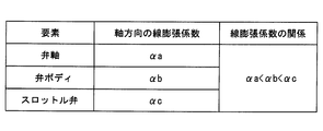
- the valve shaft 20 is made of a metal material that gives a predetermined linear expansion coefficient ⁇ a in the axial direction, for example, an iron-based material such as stainless steel.
- the valve body 40 is made of a metal material that gives a larger linear expansion coefficient ⁇ b than the valve shaft 20 in the axial direction, for example, an aluminum-based material such as an aluminum alloy.
- the throttle valve 10 is made of a metal material that gives a larger linear expansion coefficient ⁇ c in the axial direction than both the valve shaft 20 and the valve body 40, for example, an aluminum-based material such as an aluminum alloy.
- the linear expansion coefficients ⁇ c and ⁇ b of the throttle valve 10 and the valve body 40 are set larger than the linear expansion coefficient ⁇ a of the valve shaft 20 in the axial direction of the intake control device 1.
- the linear expansion coefficient ⁇ c of the throttle valve 10 is set larger than the linear expansion coefficient ⁇ b of the valve body 40 in the axial direction of the intake control device 1.
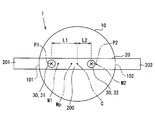
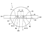
- the intersection of the center line of the first fastening member 31 and the axis O in the fastening structure 30 is defined as a first location P1
- the center line of the second fastening member 32 in the structure 30 is defined as The intersection with the axis O is defined as the second location P2.
- an edge portion of the throttle valve 10 on the first rotation shaft portion 201 side in the axial direction is defined as a first edge portion 101
- the throttle valve 10 has on the second rotation shaft portion 202 side in the axial direction.
- the edge is defined as the second edge 102.
- the midpoint between the first edge 101 and the second edge 102 in the throttle valve 10 is defined as the center point C of the valve 10 in the axial direction.
- the first location P1 is located closer to the first rotating shaft 201 in the axial direction than the center point C of the throttle valve 10.
- the first location P1 is located closer to the first rotation shaft portion 201 in the axial direction than the midpoint M1 between the center point C and the first edge portion 101.
- the second location P2 is positioned closer to the second rotation shaft portion 202 in the axial direction than the center point C of the throttle valve 10, so that the second rotation shaft portion 202 extends from the first location P1.
- the second location P2 is located closer to the axial center point C side (that is, the first rotating shaft portion 201 side) than the midpoint M2 between the central point C and the second edge 102. Yes.
- the first distance L1 from the center point C of the throttle valve 10 to the first location P1 is greater than the second distance L2 from the center point C to the second location P2. Is also set larger. Thereby, the midpoint Mp between the first location P1 and the second location P2 is shifted from the center point C of the throttle valve 10 toward the first rotation shaft portion 201 in the axial direction.
- the linear expansion coefficients ⁇ c and ⁇ b of the throttle valve 10 and the valve body 40 are set larger than the linear expansion coefficient ⁇ a of the valve shaft 20 in the axial direction of the first embodiment. Therefore, in order to suppress the interference between the throttle valve 10 and the valve body 40, the thermal deformation amount difference corresponding to the linear expansion coefficient difference ⁇ c ⁇ a between the throttle valve 10 and the valve shaft 20 and the valve body 40 and the valve shaft 20 are reduced. It is necessary to take into account the thermal deformation amount difference according to the linear expansion coefficient difference ⁇ b- ⁇ a.
- the first rotation shaft portion 201 of the valve shaft 20 is fixed to the inner ring 510 of the first bearing 51 in which the outer ring 511 is fixed to the valve body 40, so that the first bearing The pivotal support of the first rotation shaft portion 201 by 51 is realized. Therefore, in order to secure a fully closed clearance on the first rotating shaft portion 201 side and suppress interference between the throttle valve 10 and the valve body 40, a difference in thermal expansion amount between the throttle valve 10 and the valve shaft 20 and a valve It is necessary to reduce the sum of the difference in thermal expansion between the body 40 and the valve shaft 20 at a high temperature.
- the second rotating shaft portion 202 of the valve shaft 20 is slidable in the axial direction on the sliding portion 520 of the second bearing 52 where the fixing portion 521 is fixed to the valve body 40.
- the second pivot shaft 202 is pivotally supported by the second bearing 52. Therefore, in order to secure a fully closed clearance on the second rotation shaft portion 202 side and suppress interference between the throttle valve 10 and the valve body 40, a difference in heat shrinkage between the throttle valve 10 and the valve shaft 20 is determined by It is necessary to increase the heat shrinkage difference between the body 40 and the valve shaft 20 at a low temperature.
- the fastening shaft portion 200 is first fastened at the first location P1 located on the first rotating shaft portion 201 side from the center point C in the axial direction of the throttle valve 10.
- the member 31 is fastened to the throttle valve 10.
- the fastening shaft portion 200 is the second portion P2 located on the second rotating shaft portion 202 side with respect to the center point C in the axial direction of the throttle valve 10. Fastened to the throttle valve 10 by the fastening member 32.
- the first distance L1 from the center point C of the throttle valve 10 to the first location P1 in the axial direction of the first embodiment is based on the above-described knowledge about the difference in thermal expansion and thermal contraction. , Greater than the second distance L2 from the center point C to the second location P2.
- the first location P1 where the first distance L1 from the center point C in the throttle valve 10 becomes larger is the first edge 101 on the first rotating shaft portion 201 side. Proximity.
- the axial distance in the range from the first location P1 to the first edge portion 101 is reduced, and in this range, the difference in thermal expansion between the throttle valve 10 and the valve shaft 20 is as shown in FIG. Can be reduced at high temperatures. Therefore, on the first rotation shaft portion 201 side, the sum of the difference in thermal expansion between the throttle valve 10 and the valve shaft 20 and the difference in thermal expansion between the valve body 40 and the valve shaft 20 can also be reduced at high temperatures.
- FIG. 6 shows the throttle when the first distance L1 is increased in a range larger than the second distance L2 under the condition that the sum of the distances L1 and L2 is constant at 140 ° C. at a high temperature.
- the manner in which the difference in thermal expansion between the valve 10 and the valve shaft 20 is reduced is indicated by black circles.
- FIG. 6 shows the throttle valve 10 when the first distance L1 and the second distance L2 are equal under the condition that the sum of the distances L1 and L2 is the above-mentioned constant value at 140 ° C. at a high temperature.
- the difference in thermal expansion between the valve shafts 20 is indicated by a black triangle as a comparative example.
- the difference in thermal expansion amount between the throttle valve 10 and the valve shaft 20 at the assumed maximum temperature and the assumed maximum between the valve body 40 and the valve shaft 20 is set smaller than the fully closed clearance at normal temperature.
- the fully closed clearance is set smaller than the minimum width necessary for the opening / closing operation of the throttle valve 10 at any use temperature from the assumed maximum temperature to the assumed minimum temperature.
- the assumed maximum temperature is, for example, 140 ° C.
- the assumed minimum temperature is, for example, ⁇ 40 ° C.
- the second location P2 where the second distance L2 from the center point C is reduced in the throttle valve 10 is separated from the second edge 102 on the second rotating shaft 202 side.
- the axial distance in the range from the second location P2 to the second edge 102 is increased, and in this range, the heat shrinkage difference between the throttle valve 10 and the valve shaft 20 can be expanded at low temperatures.
- the difference in heat shrinkage between the throttle valve 10 and the valve shaft 20 is made larger than the difference in heat shrinkage between the valve body 40 and the valve shaft 20 at a low temperature. It becomes possible to secure the closed clearance and suppress interference between the throttle valve 10 and the valve body 40.
- the difference in heat shrinkage between the throttle valve 10 and the valve shaft 20 at the assumed minimum temperature is the assumed minimum between the valve body 40 and the valve shaft 20. It is set to be larger than the heat shrinkage difference at the time of temperature. As a result, it is possible to ensure the fully closed clearance to be equal to or larger than the minimum width necessary for the opening / closing operation of the throttle valve 10 at an arbitrary use temperature from the assumed minimum temperature to the assumed maximum temperature.
- the intake air exceeds the unavoidable flow rate from the fully closed clearance secured so as to suppress the interference between the throttle valve 10 and the valve body 40 and the throttle valve 10 is fully closed. It is also possible to avoid the situation of circulating in the intake passage. Therefore, the characteristics as the intake control device 1 can be ensured.
- the linear expansion coefficient ⁇ c of the throttle valve 10 is set larger than the linear expansion coefficient ⁇ b of the valve body 40 in the axial direction of the first embodiment, the amount of thermal expansion between the throttle valve 10 and the valve shaft 20 is set.
- the difference is likely to be larger than the difference in thermal expansion between the valve body 40 and the valve shaft 20.
- the axial distance decreases according to the setting of the distances L1 and L2, so that the temperature between the throttle valve 10 and the valve shaft 20 is high.
- the difference in the amount of thermal expansion can be reduced as much as possible.
- the first location P1 is located closer to the first rotation shaft portion 201 than the middle point M1 between the center point C and the first edge portion 101.
- the first location P1 is closer to the first edge 101 on the first rotation shaft portion 201 side than the middle point M1, in the axial range from the first location P1 to the first edge 101.
- the difference in thermal expansion between the throttle valve 10 and the valve shaft 20 can be reliably reduced at high temperatures.
- the sum of the difference in thermal expansion between the throttle valve 10 and the valve shaft 20 and the difference in thermal expansion between the valve body 40 and the valve shaft 20 is also reliably reduced at high temperatures.
- interference between the throttle valve 10 and the valve body 40 can be suppressed. Therefore, the reliability of the effect of ensuring the characteristics as the intake control device 1 can be enhanced.
- the second location P2 is located closer to the center point C than the midpoint M2 between the center point C and the second edge 102.
- the 2nd location P2 is separated from the 2nd edge 102 by the side of the 2nd rotation axial part 202 rather than the middle point M2, in the axial direction range from the 2nd location P2 to the 2nd edge 102, it is.
- the difference in heat shrinkage between the throttle valve 10 and the valve shaft 20 can be reliably expanded at low temperatures.
- the difference in heat shrinkage between the throttle valve 10 and the valve shaft 20 is surely made larger than the difference in heat shrinkage between the valve body 40 and the valve shaft 20 at a low temperature, Interference between the throttle valve 10 and the valve body 40 can be suppressed. Therefore, the reliability of the effect of ensuring the characteristics as the intake control device 1 can be enhanced.
- the second embodiment of the present disclosure is a modification of the first embodiment.
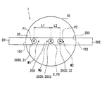
- the fastening structure 2030 according to the second embodiment is configured by combining the first fastening member 31 and the second fastening member 32 described in the first embodiment with an additional third fastening member 2033.
- the third fastening member 2033 is a screw member that cooperates with the first fastening member 31 and the second fastening member 32 to fasten the fastening shaft portion 200 to the throttle valve 10, and is formed in a male screw shape from a metal material. .
- the third fastening member 2033 has substantially the same shape and size as the first fastening member 31 and the second fastening member 32, but has a shape and size different from those of the fastening members 31 and 32. It may be done.
- the third fastening member 2033 is provided so as to correspond to the third portion P3 in the axial direction of the fastening shaft portion 200.
- the third fastening member 2033 at the third location P3 is screwed to the fastening shaft portion 200 in a state of passing through the fastening shaft portion 200 and the throttle valve 10 in the radial direction perpendicular to the penetration direction of the fitting hole 203. .
- the 3rd fastening member 2033 has implement
- the third location P3 defined at the intersection of the center line of the third fastening member 2033 and the axis O is located between the first location P1 and the second location P2 in the axial direction.
- the third portion P3 of the present embodiment substantially coincides with the center point C of the throttle valve 10.
- the fastening shaft portion 200 is fastened to the throttle valve 10 at the third place P3 between the first place P1 and the second place P2.
- the first location P1 is close to the first edge 101 of the throttle valve 10 and the second location P2 is separated from the second edge 102 of the valve 10, while ensuring the configuration with respect to the throttle valve 10. It becomes possible to increase the fastening strength of the fastening shaft portion 200 and maintain the configuration. Therefore, the effect of ensuring the characteristics as the intake control device 1 can be demonstrated for a long time.
- the linear expansion coefficient ⁇ c of the throttle valve 10 may be set to be smaller or equal to the linear expansion coefficient ⁇ b of the valve body 40.
- the throttle valve 10 is formed from a copper-based material such as brass (brass), and the valve body 40 is formed from an aluminum-based material such as an aluminum alloy, so that the linear expansion coefficient ⁇ b is smaller.
- a linear expansion coefficient ⁇ c can be realized.
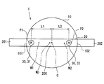
- FIG. 8 shows a third modification of the first embodiment.
- FIG. 9 shows a fourth modification of the first embodiment.
- the midpoint between the center point C and the second edge portion 102 as long as the first distance L1 is larger than the second distance L2.
- the second location P2 may be positioned closer to the second rotation shaft 202 than M2.
- FIG. 10 shows a fifth modification of the first embodiment.
- the 3rd location P3 is substantially in the midpoint Mp of those locations P1 and P2. You may match.
- the center point C of the second embodiment and the location different from the midpoint Mp of the modified example 6 Three places P3 may be set.
- a radial rolling bearing in which a plurality of roller-like rolling elements are interposed between the inner ring 510 and the outer ring 511 in a single row or double row is adopted as the “first bearing”. May be.
- an inner ring as a “sliding portion” that is slidably fitted in the axial direction with respect to the second rotating shaft portion 202, and “fixed” fixed to the valve body 40.
- a radial rolling bearing having an outer ring as a “part” may be employed as the “second bearing”.
- the rotation position of the throttle valve 10 when the energization of the electric motor 61 is stopped may be held at the fully closed position by not providing the default spring 63.
- the return spring 64 may not be provided, so that the rotational position of the throttle valve 10 when the energization of the electric motor 61 is stopped may be held at the fully open position.
Landscapes
- Engineering & Computer Science (AREA)
- General Engineering & Computer Science (AREA)
- Mechanical Engineering (AREA)
- Chemical & Material Sciences (AREA)
- Combustion & Propulsion (AREA)
- Manufacturing & Machinery (AREA)
- Control Of Throttle Valves Provided In The Intake System Or In The Exhaust System (AREA)
Abstract
Description
内燃機関の吸気通路において吸入空気の流通を制御する吸気制御装置であって、
回動により吸気通路を開閉するスロットル弁と、
スロットル弁よりも軸方向の一方側及び他方側へそれぞれ突出する第一回動軸部及び第二回動軸部、並びに第一回動軸部及び第二回動軸部の間を軸方向に接続してスロットル弁に一体回動可能に締結される締結軸部を有する弁軸と、
軸方向におけるスロットル弁の中心点よりも第一回動軸部側に位置する第一箇所において、締結軸部をスロットル弁に締結する第一締結部材と、
中心点よりも第二回動軸部側に位置する第二箇所において、締結軸部をスロットル弁に締結する第二締結部材と、
スロットル弁を収容する吸気通路を形成する弁ボディと、
弁ボディにより保持されて第一回動軸部を軸支する第一軸受と、
弁ボディにより保持されて第二回動軸部を軸支する第二軸受とを、備え、
第一軸受は、第一回動軸部に固定される内輪、並びに弁ボディに固定される外輪を有し、
第二軸受は、第二回動軸部に対して軸方向へ滑動可能に嵌合する滑動部、並びに弁ボディに固定される固定部を有し、
軸方向において、スロットル弁及び弁ボディの各線膨張係数は、弁軸の線膨張係数よりも大きく設定され、
軸方向において、中心点から第一箇所までの第一距離は、中心点から第二箇所までの第二距離よりも大きく設定される吸気制御装置を提供する。
図1~3に示すように第一実施形態による吸気制御装置1は、車両の内燃機関に搭載される。吸気制御装置1は、内燃機関の吸気通路2を開閉することで、当該通路2における吸入空気の流通を制御する。吸気制御装置1は、スロットル弁10、弁軸20、締結構造30、弁ボディ40、軸受構造50、駆動部60、センサ部70及びカバー部材80を備えている。
図4に示すように以下では、吸気制御装置1における特定要素同士の線膨張係数の関係を、説明する。
図5に示すように以下では、吸気制御装置1にて弁軸20の締結軸部200がスロットル弁10に締結される箇所P1,P2の関係を、説明する。ここで以下の説明では、締結構造30のうち第一締結部材31の中心線と軸線Oとの交点を第一箇所P1として定義する一方、同構造30のうち第二締結部材32の中心線と軸線Oとの交点を第二箇所P2として定義する。また、スロットル弁10が軸方向の第一回動軸部201側に有する縁部を、第一縁部101として定義する一方、スロットル弁10が軸方向の第二回動軸部202側に有する縁部を、第二縁部102として定義する。さらに、スロットル弁10において第一縁部101及び第二縁部102の間の中点を、軸方向における同弁10の中心点Cとして定義する。
以下、第一実施形態の作用効果を説明する。
図7に示すように本開示の第二実施形態は、第一実施形態の変形例である。第二実施形態による締結構造2030は、第一実施形態で説明した第一締結部材31及び第二締結部材32に、追加の第三締結部材2033を組み合わせて構成されている。
以上、本開示の複数の実施形態について説明したが、本開示は、それらの実施形態に限定して解釈されるものではなく、本開示の要旨を逸脱しない範囲内において種々の実施形態及び組み合わせに適用することができる。
Claims (5)
- 内燃機関の吸気通路(2)において吸入空気の流通を制御する吸気制御装置であって、
回動により前記吸気通路(2)を開閉するスロットル弁(10)と、
前記スロットル弁(10)よりも軸方向の一方側及び他方側へそれぞれ突出する第一回動軸部(201)及び第二回動軸部(202)、並びに前記第一回動軸部(201)及び第二回動軸部(202)の間を前記軸方向に接続して前記スロットル弁(10)に一体回動可能に締結される締結軸部(200)を有する弁軸(20)と、
前記軸方向における前記スロットル弁(10)の中心点(C)よりも前記第一回動軸部(201)側に位置する第一箇所(P1)において、前記締結軸部(200)を前記スロットル弁(10)に締結する第一締結部材(31)と、
前記中心点(C)よりも前記第二回動軸部(202)側に位置する第二箇所(P2)において、前記締結軸部(200)を前記スロットル弁(10)に締結する第二締結部材(32)と、
前記スロットル弁(10)を収容する前記吸気通路(2)を形成する弁ボディ(40)と、
前記弁ボディ(40)により保持されて前記第一回動軸部(201)を軸支する第一軸受(51)と、
前記弁ボディ(40)により保持されて前記第二回動軸部(202)を軸支する第二軸受(52)とを、備え、
前記第一軸受(51)は、前記第一回動軸部(201)に固定される内輪(510)、並びに前記弁ボディ(40)に固定される外輪(511)を有し、
前記第二軸受(52)は、前記第二回動軸部(202)に対して前記軸方向へ滑動可能に嵌合する滑動部(520)、並びに前記弁ボディ(40)に固定される固定部(521)を有し、
前記軸方向において、前記スロットル弁(10)及び前記弁ボディ(40)の各線膨張係数(αc,αb)は、前記弁軸(20)の線膨張係数(αa)よりも大きく設定され、
前記軸方向において、前記中心点(C)から前記第一箇所(P1)までの第一距離(L1)は、前記中心点(C)から前記第二箇所(P2)までの第二距離(L2)よりも大きく設定される、吸気制御装置。 - 前記軸方向において、前記スロットル弁(10)の線膨張係数(αc)は、前記弁ボディ(40)の線膨張係数(αb)よりも大きく設定される、請求項1に記載の吸気制御装置。
- 前記スロットル弁(10)は、前記軸方向の前記第一回動軸部(201)側に第一縁部(101)を有し、
前記第一箇所(P1)は、前記中心点(C)及び前記第一縁部(101)の間の中点(M1)よりも前記第一回動軸部(201)側に位置する、請求項1又は2に記載の吸気制御装置。 - 前記スロットル弁(10)は、前記軸方向の前記第二回動軸部(202)側に第二縁部(102)を有し、
前記第二箇所(P2)は、前記中心点(C)及び前記第二縁部(102)の間の中点(M2)よりも前記中心点(C)側に位置する、請求項1~3のいずれか一項に記載の吸気制御装置。 - 前記第一箇所(P1)及び前記第二箇所(P2)の間に位置する第三箇所(P3)において、前記締結軸部(200)を前記スロットル弁(10)に締結する第三締結部材(2033)を備える、請求項1~4のいずれか一項に記載の吸気制御装置。
Priority Applications (4)
| Application Number | Priority Date | Filing Date | Title |
|---|---|---|---|
| DE112016004470.4T DE112016004470T5 (de) | 2015-10-02 | 2016-09-07 | Einlassluftsteuerungsvorrichtung |
| KR1020187009160A KR101957358B1 (ko) | 2015-10-02 | 2016-09-07 | 흡기제어장치 |
| CN201680058397.7A CN108138662A (zh) | 2015-10-02 | 2016-09-07 | 进气控制装置 |
| US15/763,287 US10364756B2 (en) | 2015-10-02 | 2016-09-07 | Intake air control device |
Applications Claiming Priority (2)
| Application Number | Priority Date | Filing Date | Title |
|---|---|---|---|
| JP2015-197147 | 2015-10-02 | ||
| JP2015197147A JP6354724B2 (ja) | 2015-10-02 | 2015-10-02 | 吸気制御装置 |
Publications (1)
| Publication Number | Publication Date |
|---|---|
| WO2017056883A1 true WO2017056883A1 (ja) | 2017-04-06 |
Family
ID=58423349
Family Applications (1)
| Application Number | Title | Priority Date | Filing Date |
|---|---|---|---|
| PCT/JP2016/076240 Ceased WO2017056883A1 (ja) | 2015-10-02 | 2016-09-07 | 吸気制御装置 |
Country Status (6)
| Country | Link |
|---|---|
| US (1) | US10364756B2 (ja) |
| JP (1) | JP6354724B2 (ja) |
| KR (1) | KR101957358B1 (ja) |
| CN (1) | CN108138662A (ja) |
| DE (1) | DE112016004470T5 (ja) |
| WO (1) | WO2017056883A1 (ja) |
Families Citing this family (5)
| Publication number | Priority date | Publication date | Assignee | Title |
|---|---|---|---|---|
| FR3083286B1 (fr) * | 2018-06-27 | 2022-02-11 | Faurecia Systemes Dechappement | Vanne pourvue d'un organe de stabilisation solidaire du volet et ligne d'echappement equipee d'une telle vanne |
| EP3842734B1 (en) * | 2018-08-23 | 2024-05-08 | Mikuni Corporation | Electronically controlled throttle device for engine |
| CN109340385B (zh) * | 2018-11-30 | 2024-07-02 | 郑州光大阀门制造有限公司 | 一种烟气脱硫系统用单板柔缘挡风门 |
| TWI878561B (zh) * | 2020-07-31 | 2025-04-01 | 日商旭有機材股份有限公司 | 蝶形閥 |
| CN116717385A (zh) * | 2023-05-29 | 2023-09-08 | 湛江德利车辆部件有限公司 | 一种节气门体、电子节气门系统及控制方法 |
Citations (4)
| Publication number | Priority date | Publication date | Assignee | Title |
|---|---|---|---|---|
| JPS62128115U (ja) * | 1986-02-04 | 1987-08-13 | ||
| JPH01249931A (ja) * | 1988-03-31 | 1989-10-05 | Hitachi Ltd | 絞弁組立体 |
| JP2001132480A (ja) * | 1999-11-01 | 2001-05-15 | Denso Corp | 内燃機関用吸気制御装置 |
| JP2009216184A (ja) * | 2008-03-11 | 2009-09-24 | Calsonic Kansei Corp | バタフライバルブ |
Family Cites Families (21)
| Publication number | Priority date | Publication date | Assignee | Title |
|---|---|---|---|---|
| JPS62128115A (ja) * | 1985-11-28 | 1987-06-10 | Fujitsu Ltd | 化合物半導体結晶の製造方法 |
| JPS62129538A (ja) | 1985-11-29 | 1987-06-11 | Toyota Motor Corp | スロツトル弁の支持構造 |
| US4880207A (en) * | 1987-03-02 | 1989-11-14 | Mitsubishi Denki Kabushiki Kaisha | Intake throttle valve return device of engine |
| US5492097A (en) * | 1994-09-30 | 1996-02-20 | General Motors Corporation | Throttle body default actuation |
| DE19510622A1 (de) * | 1995-03-23 | 1996-09-26 | Bosch Gmbh Robert | Drosselvorrichtung und Verfahren zur Herstellung einer Drosselvorrichtung |
| JP3323356B2 (ja) * | 1995-04-07 | 2002-09-09 | 株式会社ケーヒン | 絞り弁制御装置 |
| DE60025981T2 (de) * | 1999-11-01 | 2006-09-07 | Denso Corp., Kariya | Einlassluftsteuerungsventil für Brennkraftmaschine und Verfahren zu seiner Herstellung |
| JP3728175B2 (ja) * | 2000-05-16 | 2005-12-21 | 三菱電機株式会社 | 内燃機関の吸気量制御装置 |
| JP3893907B2 (ja) * | 2001-06-14 | 2007-03-14 | 株式会社デンソー | 内燃機関用吸気制御装置 |
| EP1674695B1 (en) * | 2002-03-06 | 2008-08-06 | Borgwarner, Inc. | Assembly for electronic throttle control with position sensor |
| JP2004132232A (ja) * | 2002-10-09 | 2004-04-30 | Aisan Ind Co Ltd | スロットル制御装置 |
| JP2005299457A (ja) * | 2004-04-09 | 2005-10-27 | Isuzu Motors Ltd | エンジンの排気ガス絞り弁 |
| WO2007135840A1 (ja) * | 2006-05-24 | 2007-11-29 | Toyota Jidosha Kabushiki Kaisha | 内燃機関の吸気装置 |
| JP4353291B2 (ja) * | 2007-09-20 | 2009-10-28 | 株式会社デンソー | バルブ開閉制御装置 |
| KR100931040B1 (ko) * | 2007-11-07 | 2009-12-10 | 현대자동차주식회사 | 제1 밸브 플레이트와 제2 밸브 플레이트를 구비한 스로틀밸브 세트 |
| JP2011231625A (ja) | 2010-04-23 | 2011-11-17 | Denso Corp | エンジン用スロットル装置 |
| JP5729218B2 (ja) | 2011-08-26 | 2015-06-03 | 株式会社デンソー | 電子スロットル |
| JP5885202B2 (ja) * | 2012-03-30 | 2016-03-15 | 株式会社ケーヒン | シール付き転がり軸受 |
| JP2013253490A (ja) | 2012-06-05 | 2013-12-19 | Denso Corp | スロットル装置 |
| JP6337539B2 (ja) * | 2014-03-18 | 2018-06-06 | アイシン精機株式会社 | 吸気制御弁および吸気装置 |
| JP2015197147A (ja) | 2014-03-31 | 2015-11-09 | アイシン・エィ・ダブリュ株式会社 | 車両用駆動装置の油圧制御装置 |
-
2015
- 2015-10-02 JP JP2015197147A patent/JP6354724B2/ja not_active Expired - Fee Related
-
2016
- 2016-09-07 CN CN201680058397.7A patent/CN108138662A/zh active Pending
- 2016-09-07 KR KR1020187009160A patent/KR101957358B1/ko not_active Expired - Fee Related
- 2016-09-07 WO PCT/JP2016/076240 patent/WO2017056883A1/ja not_active Ceased
- 2016-09-07 DE DE112016004470.4T patent/DE112016004470T5/de not_active Withdrawn
- 2016-09-07 US US15/763,287 patent/US10364756B2/en not_active Expired - Fee Related
Patent Citations (4)
| Publication number | Priority date | Publication date | Assignee | Title |
|---|---|---|---|---|
| JPS62128115U (ja) * | 1986-02-04 | 1987-08-13 | ||
| JPH01249931A (ja) * | 1988-03-31 | 1989-10-05 | Hitachi Ltd | 絞弁組立体 |
| JP2001132480A (ja) * | 1999-11-01 | 2001-05-15 | Denso Corp | 内燃機関用吸気制御装置 |
| JP2009216184A (ja) * | 2008-03-11 | 2009-09-24 | Calsonic Kansei Corp | バタフライバルブ |
Also Published As
| Publication number | Publication date |
|---|---|
| CN108138662A (zh) | 2018-06-08 |
| JP6354724B2 (ja) | 2018-07-11 |
| KR20180048935A (ko) | 2018-05-10 |
| US20180274452A1 (en) | 2018-09-27 |
| US10364756B2 (en) | 2019-07-30 |
| DE112016004470T5 (de) | 2018-06-21 |
| KR101957358B1 (ko) | 2019-06-27 |
| JP2017067058A (ja) | 2017-04-06 |
Similar Documents
| Publication | Publication Date | Title |
|---|---|---|
| JP6354724B2 (ja) | 吸気制御装置 | |
| US10428889B2 (en) | Torsion spring | |
| JP7107679B2 (ja) | バルブ装置 | |
| JP7259637B2 (ja) | 絞り弁装置 | |
| US20120326069A1 (en) | Step type valve | |
| US20140252259A1 (en) | Butterfly valve | |
| US20170342914A1 (en) | Valve device | |
| US20150315984A1 (en) | Flap device for an internal combustion engine | |
| US10408170B2 (en) | EGR cooler bypass valve | |
| JP2017110525A (ja) | 内燃機関用電子式スロットル装置 | |
| US11060447B2 (en) | Charging device with a wastegate valve device | |
| WO2020129849A1 (ja) | スロットル装置、及び、スロットル装置の製造方法 | |
| JP2014173438A (ja) | スロットルボディ | |
| JP2020003023A (ja) | 弁装置 | |
| WO2017057080A1 (ja) | 捩りばね | |
| CN104279087A (zh) | 阀装置 | |
| JP6384354B2 (ja) | 電子スロットル | |
| WO2019009134A1 (ja) | 絞り弁装置 | |
| JP5828303B2 (ja) | バルブ装置 | |
| JP7101459B2 (ja) | 電動アクチュエータ | |
| JP6188439B2 (ja) | 内燃機関の吸気装置 | |
| JP6456730B2 (ja) | スロットル装置 | |
| JP2007028706A (ja) | ステータ及びブラシレスモータ | |
| JP6443310B2 (ja) | 弁装置 | |
| WO2015111480A1 (ja) | 排気流路用弁装置 |
Legal Events
| Date | Code | Title | Description |
|---|---|---|---|
| 121 | Ep: the epo has been informed by wipo that ep was designated in this application |
Ref document number: 16851057 Country of ref document: EP Kind code of ref document: A1 |
|
| WWE | Wipo information: entry into national phase |
Ref document number: 15763287 Country of ref document: US |
|
| ENP | Entry into the national phase |
Ref document number: 20187009160 Country of ref document: KR Kind code of ref document: A |
|
| WWE | Wipo information: entry into national phase |
Ref document number: 112016004470 Country of ref document: DE |
|
| 122 | Ep: pct application non-entry in european phase |
Ref document number: 16851057 Country of ref document: EP Kind code of ref document: A1 |