WO2017056765A1 - 歯車支持装置 - Google Patents
歯車支持装置 Download PDFInfo
- Publication number
- WO2017056765A1 WO2017056765A1 PCT/JP2016/073982 JP2016073982W WO2017056765A1 WO 2017056765 A1 WO2017056765 A1 WO 2017056765A1 JP 2016073982 W JP2016073982 W JP 2016073982W WO 2017056765 A1 WO2017056765 A1 WO 2017056765A1
- Authority
- WO
- WIPO (PCT)
- Prior art keywords
- gear
- base
- fixed base
- fixed
- support device
- Prior art date
- Legal status (The legal status is an assumption and is not a legal conclusion. Google has not performed a legal analysis and makes no representation as to the accuracy of the status listed.)
- Ceased
Links
Images





Classifications
-
- F—MECHANICAL ENGINEERING; LIGHTING; HEATING; WEAPONS; BLASTING
- F16—ENGINEERING ELEMENTS AND UNITS; GENERAL MEASURES FOR PRODUCING AND MAINTAINING EFFECTIVE FUNCTIONING OF MACHINES OR INSTALLATIONS; THERMAL INSULATION IN GENERAL
- F16H—GEARING
- F16H55/00—Elements with teeth or friction surfaces for conveying motion; Worms, pulleys or sheaves for gearing mechanisms
- F16H55/02—Toothed members; Worms
- F16H55/26—Racks
Definitions
- the present invention relates to a gear support device for properly meshing a reference gantry side gear with another gantry side rack gear or another gear.
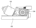
- an electric slide device described in International Publication WO2011 / 036984A1 is provided with a rack gear 102 provided on a platform (not shown) and a reference frame (not shown) that supports the platform so as to be horizontally slidable.
- a motor 103 and a pinion gear 104 are provided.
- the rack gear 102 is fixed to the side surface of the platform so as to extend in the sliding direction.
- the motor 103 is fixed at a predetermined position of the reference frame, and a pinion gear 104 is attached to the drive shaft of the motor 103.
- the pinion gear 104 meshes with the rack gear 102 as shown in FIG.
- the platform slides horizontally with respect to the reference frame by the meshing action of the rack gear 102 and the pinion gear 104.
- the invention according to claim 1 includes at least one gear, and is fixed at a predetermined position of the reference frame so that the gear can be engaged with a rack gear provided on another frame or another gear.
- a fixed base fixed to the reference frame, a position adjusting base connected to the fixed base in a rotatable state, and a position adjusting base.
- the first gear provided on the position adjusting base at a position away from the center of rotation, the first gear and the rack gear, or the first backlash between the other gears and the first backlash.
- a position adjusting mechanism capable of adjusting a rotation angle of the position adjusting base with respect to the fixed base so that the gears can be displaced with respect to the fixed base.
- the position adjustment mechanism of the gear support device is a position adjustment base for the fixed base so that the gear can be displaced relative to the fixed base by an appropriate amount of backlash between the gear and the rack gear (another gear). Can be adjusted. For this reason, for example, after fixing the fixed base to the reference frame with zero backlash between the gear and the rack gear (another gear), the position adjustment mechanism adjusts the rotation angle of the position adjustment base relative to the fixed base.
- the backlash can be set to an appropriate value. That is, after fixing the fixed base of the gear support device to the reference frame, the position adjustment base is rotated with respect to the fixed base by the position adjustment mechanism, and the backlash between the gear and the rack gear (another gear) is set to an appropriate value. This makes it easy to adjust the backlash.
- the position adjusting mechanism is provided on the other of the first bolt hole formed in one of the fixed base and the position adjusting base, and the fixed base and the position adjusting base.
- a second bolt hole having a diameter larger than that of the first bolt hole, and a bolt having a diameter substantially the same as that of the first bolt hole and passed through the first bolt hole and the second bolt hole.
- the position adjustment base rotates relative to the fixed base by a difference in diameter between the bolt and the second bolt hole, so that the first gear backlashes with respect to the fixed base. It is displaced by the appropriate value. That is, since the position adjusting base is rotated with respect to the fixed base by the difference in diameter between the bolt and the second bolt hole, the structure of the position adjusting mechanism is simplified.
- the second gear is provided at the position of the rotation center of the position adjusting base, and when the backlash between the first gear and the rack gear is zero, the second gear The positional relationship between the first gear and the second gear is set so that the backlash between the rack gears becomes an appropriate value. For this reason, even when the gear support device has a plurality of gears (first and second gears), the backlash between each gear and the rack gear can be set to an appropriate value.
- the fixed base is temporarily fixed in a state in which the fixed base can be rotated in the vertical direction with respect to the reference frame, and the first gear meshes with the rack gear or another gear,
- the fixed base is configured to be fixed to the reference frame. For this reason, it becomes easy to mesh the first gear and the rack gear (another gear).
- the fixed base is provided with a handle that can be gripped when the fixed base is rotated in the vertical direction within a certain range with respect to the reference frame. For this reason, the fixed base can be easily turned up and down with respect to the reference frame.
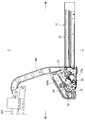
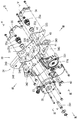
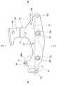
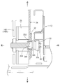
- FIG. 4 It is a whole perspective view showing the wheelchair lifter of a passenger car using an electric slide device provided with the gear support device concerning Embodiment 1 of the present invention. It is the side view which looked at the operation of the wheelchair lifter from the vehicle left side. It is the side view (III-III arrow line view of FIG. 4) which looked at the gear support apparatus which concerns on the said electric slide apparatus and this embodiment which comprises the electric slide apparatus from the vehicle left side (vehicle width direction outer side). It is a disassembled perspective view of the said gear support apparatus. It is the side view which looked at the said gear support apparatus from the vehicle right side (vehicle width direction inner side). It is the side view which looked at the fixed base of the said gearwheel support apparatus, the base for position adjustment, etc.
- the gear support device according to Embodiment 1 of the present invention is a device used in the electric slide device 20 of the wheelchair lifter 10 installed in the welfare vehicle C.
- front, rear, left and right and up and down in the figure correspond to front, back, left and right and up and down of the welfare vehicle C including the wheelchair lifter 10.
- the wheelchair lifter 10 is a device for getting a passenger in and out of the rear opening H of the welfare vehicle C (hereinafter referred to as the vehicle C) with the wheelchair K.
- the wheelchair lifter 10 includes a horizontal platform 12 on which the wheelchair K is placed, a pair of left and right lifting link mechanisms 14 that lift and lower the platform 12 in a horizontal state, and the platform 12 as a lifting link mechanism 14.
- the electric slide device 20 is configured to slide back and forth.
- the elevating link mechanism 14 is connected to both rear ends (left and right) of the passenger compartment floor FL by left and right fixing brackets 141.
- the elevating link mechanism 14 includes a pair of left and right four-bar linkage mechanisms 143, a pair of left and right elevating arms 144, and a pair of left and right holders 148. Then, the base end portions of the left and right four-bar linkage mechanisms 143 are connected to the left and right fixing brackets 141 so as to be vertically rotatable.
- the left and right lifting arms 144 are connected to the distal ends of the left and right four-bar linkage mechanisms 143 so as to be relatively rotatable in the vertical direction.
- the left and right holders 148 that support the platform 12 in a state where the platform 12 can slide back and forth are provided at the lower ends of the left and right lifting arms 144.
- the holder 148 and the platform 12 are provided with an electric slide device 20 for sliding the platform 12 back and forth with respect to the holder 148.
- the electric slide device 20 is a slide device using a rack and pinion meshing structure.
- the electric slide device 20 includes a motor 23, a speed reducer 23 g (hereinafter referred to as “motor 23”), and a brake 25 provided in the left holder 148, as shown in a side view as viewed from the left side of the vehicle in FIG. 3. Yes. 4 and 5, the motor pinion gear 23p attached to the output shaft 231 of the motor 23 (decelerator 23g) and the brake pinion gear 25p attached to the output shaft 251 of the brake 25 are used as a platform. 12 is meshed with a rack gear 22 provided downward on the left side surface.
- FIG. 5 is a schematic view taken along the arrow VV in FIG. 4, and shows the electric slide device 20 from the opposite side (vehicle right side (vehicle width direction inner side)) with respect to FIG. 3.
- the brake 25 is attached to the mount 148k of the holder 148 via a fixed base 34 of a gear support device 30 (described later). Further, the motor 23 is fixed to a position adjusting base 32 of the gear support device 30, and the position adjusting base 32 is attached to a frame 148 k of the holder 148 via a fixed base 34. That is, the frame 148k of the holder 148 corresponds to the reference frame of the present invention. Further, the platform 12 including the rack gear 22 corresponds to another gantry of the present invention.
- the gear support device 30 meshes the motor pinion gear 23p and the brake pinion gear 25p on the holder 148 side with the rack gear 22 on the platform 12 side, the backlash of the backlash that is a clearance in the movement direction between the two 23p (25p) and 22 is provided. It is a device that can be adjusted easily.
- the gear support device 30 includes a position adjustment base 32 to which the motor 23 is attached, and a fixed base 34 to which the position adjustment base 32 is rotatably supported and the brake 25 is attached.
- the fixed base 34 of the gear support device 30 is formed in a substantially inverted T-shape from the base main body 340 and the handle 348 as shown in the side views of the vehicle right side (vehicle width direction inner side) in FIGS. 4 and 7. It is the formed plate-like base.
- the fixed base 34 is arranged so that the base main body 340 extends in the vehicle front-rear direction with the handle 348 standing upright.
- a bearing hole 341 is formed in the base main body 340 of the fixed base 34 below the handle portion 348.
- a bearing hole 321 having the same diameter as the bearing hole 341 of the fixed base 34 is also formed in the position adjusting base 32 described later.
- the position adjusting base 32 has a position of the bearing hole 321 that matches the position of the bearing hole 341 of the fixed base 34. As shown in the figure, it is superimposed on the right side surface (the surface side in FIG. 7) of the fixed base 34.
- a brake bearing portion 25j that rotatably supports the output shaft 251 of the brake 25 is fitted into the bearing hole 341 of the fixed base 34 and the bearing hole 321 of the position adjusting base 32.
- the brake 25 is attached to the left side of the base body 340 of the fixed base 34 (the back side in FIGS. 6, 7 (outer side in the vehicle width direction)) with screws or the like. ing.
- the output shaft 251 of the brake 25 is passed through a brake bearing portion 25 j provided in bearing holes 341 and 321 between the fixed base 34 and the position adjusting base 32.
- the output shaft 251 of the brake 25 protrudes in the right direction with respect to the fixed base 34 and the position adjusting base 32, and a brake pinion gear 25p is attached to the right end portion of the output shaft 251.
- the position adjusting base 32 can rotate with respect to the fixed base 34 around the output shaft 251 of the brake 25 and the brake bearing portion 25j.
- a front bolt hole 342 for attaching the fixed base 34 to the mount 148 k of the holder 148 is formed at the front end of the fixed base 34 (base body 340).
- a rear bolt long hole 343 for attaching the fixed base 34 to the mount 148k of the holder 148 is formed at the rear end of the fixed base 34.
- the rear bolt elongated hole 343 has a length dimension so that the fixed base 34 can be rotated up and down within a certain range around a bolt (not shown) passed through the front bolt hole 342.
- an upper bolt hole 349 for attaching the fixed base 34 to the mount 148k of the holder 148 is formed in the upper center of the handle portion 348 of the fixed base 34.
- the output shaft 231 of the motor 23 and the motor bearing portion 23j attached to the position adjusting base 32 are passed through the position behind the fixed base 34 (base body portion 340).
- An escape hole 345 is formed.
- the escape hole 345 has an output shaft 231 of the motor 23 and the like so as not to prevent rotation of the position adjusting base 32 with respect to the fixed base 34 within a predetermined range. Is set to a sufficiently large diameter.
- the position adjusting base 32 of the gear support device 30 is a plate-like base formed in a substantially flat L shape by a base main body portion 320 and a rear upper overhanging portion 328. As described above, the position adjusting base 32 is configured to overlap the fixed base 34 from the right side, that is, from the inner side in the vehicle width direction (see FIGS. 8 and 9). As shown in FIG. 6, the base body 320 of the position adjusting base 32 is formed with a bearing hole 321 into which the brake bearing 25j described above is fitted. The base body 320 of the position adjusting base 32 is formed with a bearing hole 325 into which the motor bearing 23j (see FIGS. 4 and 9) is fitted below the rear upper overhanging portion 328.
- the motor 23 is mounted so as not to interfere with the fixed base 34.
- the output shaft 231 of the motor 23 is passed through the motor bearing portion 23 j of the position adjusting base 32 (bearing hole 325) inside the escape hole 345 of the fixed base 34.
- the output shaft 231 of the motor 23 projects rightward with respect to the fixed base 34 and the position adjusting base 32, and a motor pinion gear 23p is attached to the right end of the output shaft 231.
- the position adjustment base 32 corresponds to the difference in diameter between the escape hole 345 of the fixed base 34 and the motor bearing portion 23j of the position adjustment base 32 (bearing hole 325) with respect to the fixed base 34. It becomes possible to rotate around the output shaft 251 of the brake 25 by an angle.
- a position adjustment mechanism 40 for adjusting the rotation angle of the position adjustment base 32 with respect to the fixed base 34 is provided as shown in FIG.
- the position adjusting mechanism 40 rotates the position adjusting base 32 with respect to the fixed base 34 so that the motor pinion gear 23p can be displaced with respect to the fixed base 34 by an appropriate amount of backlash between the motor pinion gear 23p and the rack gear 22. It is a mechanism for adjusting the angle.
- the position adjustment mechanism 40 includes a first bolt hole 41 formed in the fixed base 34 as shown in FIG. 7 and the like, and a second bolt hole 42 formed in the position adjustment base 32 as shown in FIG. The insertion bolt 43 is inserted into the first and second bolt holes 41 and 42 (see FIG. 4).
- the first bolt hole 41 is formed in a disk protrusion 340 t at the rear upper part of the fixed base 34 (base main body 340), and has a diameter dimension substantially equal to that of the insertion bolt 43. Is set.
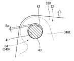
- the second bolt hole 42 is formed at the corner of the rear upper overhanging portion 328 of the position adjusting base 32, and as shown in FIG. 10, the second bolt hole 42 is larger than the diameter of the insertion bolt 43 (first bolt hole 41). Bo is set to a large value.
- the position adjustment base 32 is configured so that the output shaft of the brake 25 has an angle corresponding to a difference in diameter (dimension Bo) between the insertion bolt 43 of the position adjustment mechanism 40 and the second bolt hole 42 with respect to the fixed base 34. It can be rotated around 251.
- the dimension Bo is set to a value smaller than the difference in diameter between the escape hole 345 of the fixed base 34 and the motor bearing portion 23j of the position adjustment base 32 (bearing hole 325).
- the dimension Bo is such that when the position adjusting base 32 is rotated with respect to the fixed base 34 by an angle corresponding to the dimension Bo, the motor pinion gear 23p has an appropriate backlash value Bk ( (See FIG. 13).
- the position adjusting base 32 and the fixed base 34 are divided into three sets for connecting the positions 32 and 34 to each other after adjusting the position of the position adjusting base 32 with respect to the fixed base 34 by the position adjusting mechanism 40.
- Connection mechanisms 51, 52, and 53 are provided.
- the first connecting mechanism 51, the second connecting mechanism 52, and the third connecting mechanism 53 are disposed at an upper position of the brake pinion gear 25p with an interval, as shown in FIG.
- the protruding shaft of the brake pinion gear 25p and the protruding shaft of the motor pinion gear 23p are rotatably supported on the right side surface of the position adjusting base 32, respectively.
- a front support 55 and a rear support 56 are attached.
- the motor 23 is attached to the position adjustment base 32.
- the output shaft 231 of the motor 23 is passed through the motor bearing portion 23j of the position adjusting base 32 (bearing hole 325) inside the escape hole 345 of the fixed base 34 as shown in FIG.
- the protruding shaft of the motor pinion gear 23 p provided on the output shaft 231 of the motor 23 is supported by the rear support 56, and the rear support 56 is attached to the position adjustment base 32.
- the insertion bolt 43 is inserted into the first bolt hole 41 of the fixed base 34 and the second bolt hole 42 of the position adjustment base 32 constituting the position adjustment mechanism 40.
- the position adjusting base 32 is pulled upward with respect to the fixed base 34.
- the position adjustment base 32 rotates upward (right rotation in FIG. 6) about the output shaft 251 of the brake 25 with respect to the fixed base 34, and the insertion bolt 43 and the position adjustment base 32 A gap Bo is formed between the two bolt holes 42 above.
- a nut (not shown) is screwed into the insertion bolt 43, and the position adjustment base 32 is temporarily fixed to the fixed base 34. That is, the position adjustment base 32 is held at the upper limit position with respect to the fixed base 34.
- the fixed base 34 is set with respect to the base 148k of the holder 148, and the front bolt hole 342 and the rear bolt long hole 343 of the fixed base 34 are temporarily fixed to the base 148k with bolts. That is, the fixed base 34 can be turned up and down by the length of the rear bolt long hole 343 around the bolt (not shown) passed through the front bolt hole 342 with respect to the mount 148k of the holder 148.
- the platform 12 is moved back and forth to a predetermined position, and the rack gear 22 is disposed above the brake pinion gear 25p and the motor pinion gear 23p.
- the fixed base 34 is pulled up using the handle portion 348, so that the fixed base 34 is rotated upward around a bolt (not shown) in the front bolt hole 342, and the motor pinion gear 23p,
- the brake pinion gear 25 p meshes with the rack gear 22.
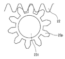
- the motor pinion gear 23p and the rack gear 22 are meshed with each other with zero backlash.
- the brake pinion gear 25p is connected to the motor pinion gear 23p so that the backlash between the brake pinion gear 25p and the rack gear 22 becomes an appropriate value when the motor pinion gear 23p meshes with the rack gear 22 with zero backlash. It is positioned with respect to it.
- the fixed base 34 is formally fixed to the frame 148k of the holder 148. That is, the fixed base 34 is bolted to the frame 148k of the holder 148 with an appropriate torque at the position of the front bolt hole 342 and the rear bolt long hole 343, and the fixed base 34 is fixed to the holder 148 at the position of the upper bolt hole 349. It is bolted to the gantry 148k.
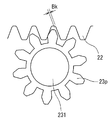
- the motor pinion gear 23p provided on the position adjustment base 32 is lowered by the dimension Bk with respect to the fixed base 34, and the backlash between the motor pinion gear 23p and the rack gear 22 is proper as shown in FIG. It is held at the value Bk.
- the insertion bolt 43 and the nut of the position adjusting mechanism 40 are tightened with an appropriate torque, and the position adjusting base 32 and the fixed base 34 are connected. Further, the position adjusting base 32 and the fixed base 34 are connected by the first connecting mechanism 51, the second connecting mechanism 52, and the third connecting mechanism 53. Thereby, the attachment of the gear support device 30 to the gantry 148k of the holder 148 is completed. That is, the motor pinion gear 23p corresponds to the first gear of the present invention, and the brake pinion gear 25p corresponds to the second gear of the present invention.
- the position adjusting mechanism 40 is configured such that the motor pinion gear 23p is displaced with respect to the fixed base 34 by an appropriate value Bk of the backlash between the motor pinion gear 23p (gear) and the rack gear 22.
- the rotation angle of the position adjusting base 32 with respect to the fixed base 34 can be adjusted so that it can be performed. Therefore, for example, after the fixed base 34 is fixed to the frame 148k (reference frame) of the holder 148 with zero backlash between the motor pinion gear 23p and the rack gear 22, the position adjustment mechanism 40 adjusts the position of the fixed base 34.
- the backlash can be set to an appropriate value by adjusting the rotation angle of the base 32 for use. That is, after the fixed base 34 of the gear support device 30 is fixed to the frame 148k of the holder 148, the position adjusting base 32 is rotated with respect to the fixed base 34 by the position adjusting mechanism 40 so that the motor pinion gear 23p and the rack gear 22 are located. Since the backlash can be set to an appropriate value, the backlash can be easily adjusted.
- the position adjustment mechanism 40 is configured to rotate the position adjustment base 32 with respect to the fixed base 34 by the difference in diameter between the insertion bolt 43 and the second bolt hole 42, the position adjustment mechanism 40 has a configuration. It will be easy. Further, even when the gear support device 30 includes a plurality of gears (motor pinion gear 23p, brake pinion gear 25p), the backlash between each gear and the rack gear 22 can be set to an appropriate value. Further, the fixed base 34 is configured to be capable of rotating in the vertical direction within a certain range with respect to the gantry 148k (reference gantry) of the holder 148. Therefore, it becomes easy to mesh the motor pinion gear 23p and the rack gear 22, and the brake pinion gear 25p and the rack gear 22. Further, since the fixed base 34 is provided with the handle portion 348, the fixed base 34 can be easily rotated up and down with respect to the frame 148k (reference frame) of the holder 148.
- the present invention is not limited to the above-described embodiment, and can be modified without departing from the gist of the present invention.
- the gear support apparatus 30 provided with the pinion gear 23p for motors and the pinion gear 25p for brakes was illustrated.
- the brake 25 and the brake pinion gear 25p are omitted, and the fixed base 34 and the position adjustment base 32 are connected in a relatively rotatable state using a connecting shaft instead of the output shaft 251 of the brake 25.
- the position adjustment mechanism 40 provided with the 1st bolt hole 41, the 2nd bolt hole 42, and the insertion bolt 43 was illustrated.
- a position adjusting mechanism having a configuration in which the positioning pin is passed through the positioning hole while the position adjusting base 32 is shifted by the backlash with respect to the fixed base 34 is also possible.
- the gear support device 30 that adjusts the backlash between the motor pinion gear 23p (gear) and the rack gear 22 to an appropriate value is illustrated.
Landscapes
- Engineering & Computer Science (AREA)
- General Engineering & Computer Science (AREA)
- Mechanical Engineering (AREA)
- Gear Transmission (AREA)
- Gears, Cams (AREA)
Abstract
本発明は、少なくとも1個の歯車を備えており、基準架台の所定位置に固定されることで、歯車を別の架台に設けられたラックギヤと噛合させられるように構成された歯車支持装置であって、基準架台に固定される固定ベース(34)と、固定ベース(34)に対して回動可能に連結されている位置調整用ベース(32)と、位置調整用ベース(32)の回動中心(251)から離れた位置で位置調整用ベースに設けられている第1の歯車(23p)と、第1の歯車(23p)とラックギヤ(22)間のバックラッシュの適正値分だけ第1の歯車(23p)が固定ベース(34)に対して変位できるように、固定ベース(34)に対する位置調整用ベース(32)の回動角度を調整可能な位置調整機構(40)とを有する。
Description
本発明は、基準架台側の歯車と別の架台側のラックギヤ、あるいは別の歯車とを適正に噛合させるための歯車支持装置に関する。
ラック・ピニオン機構を備える電動スライド装置に関する技術が国際公開WO2011/036984A1に記載されている。国際公開WO2011/036984A1に記載された電動スライド装置は、図14に示すように、プラットホーム(図示省略)に設けられたラックギヤ102と、前記プラットホームを水平スライド可能に支持する基準架台(図示省略)に設けられたモータ103、及びピニオンギヤ104とを備えている。ラックギヤ102は、前記プラットホームの側面にスライド方向に延びるように固定されている。モータ103は、前記基準架台の所定位置に固定されており、前記モータ103の駆動軸にピニオンギヤ104が取付けられている。そして、ピニオンギヤ104が、図14に示すように、ラックギヤ102と噛合している。これにより、前記モータが駆動されることで、ラックギヤ102とピニオンギヤ104との噛合作用により、前記プラットホームが前記基準架台に対して水平にスライドする。
前記電動スライド装置においてラックギヤ102とピニオンギヤ104とを噛合させる際、ラックギヤ102とピニオンギヤ104間の運動方向の隙間であるバックラッシュを適正値に管理するのが難しい。現状では、ラックギヤ102とピニオンギヤ104間に薄板であるシムを挟んで組み立て、その後、シムを抜き取ることが行なわれている。しかし、ピニオンギヤ104が狭い場所に設置されている場合には、前記シムを使用することが難しい。
したがって、改良された歯車支持装置が必要とされている。
上記した課題は、各請求項の発明によって解決される。請求項1の発明は、少なくとも1個の歯車を備えており、基準架台の所定位置に固定されることで、前記歯車を別の架台に設けられたラックギヤ、あるいは別の歯車と噛合させられるように構成された歯車支持装置であって、前記基準架台に固定される固定ベースと、前記固定ベースに対して回動可能な状態で連結されている位置調整用ベースと、前記位置調整用ベースの回動中心から離れた位置で、前記位置調整用ベースに設けられている第1の歯車と、前記第1の歯車と前記ラックギヤ、あるいは別の歯車間のバックラッシュの適正値分だけ前記第1の歯車が前記固定ベースに対して変位できるように、前記固定ベースに対する前記位置調整用ベースの回動角度を調整可能な位置調整機構とを有する。
本発明によると、歯車支持装置の位置調整機構は、歯車とラックギヤ(別の歯車)間のバックラッシュの適正値分だけ歯車が固定ベースに対して変位できるように、固定ベースに対する位置調整用ベースの回動角度を調整できる。このため、例えば、歯車とラックギヤ(別の歯車)間のバックラッシュが零の状態で固定ベースを基準架台に固定した後、位置調整機構により固定ベースに対する位置調整用ベースの回動角度を調整して前記バックラッシュを適正値にできる。即ち、歯車支持装置の固定ベースを基準架台に固定した後、位置調整機構により固定ベースに対して位置調整用ベースを回動させて歯車とラックギヤ(別の歯車)間のバックラッシュを適正値にできるため、前記バックラッシュの調整が容易になる。
請求項2の発明によると、位置調整機構は、固定ベースと位置調整用ベースとのいずれか一方に形成された第1ボルト孔と、前記固定ベースと前記位置調整用ベースとのいずれか他方に形成されて、前記第1ボルト孔よりも大径の第2ボルト孔と、前記第1ボルト孔とほぼ等しい径寸法で、前記第1ボルト孔と第2ボルト孔とに通されるボルトとを有しており、前記ボルトと第2ボルト孔との径寸法差だけ前記位置調整用ベースが前記固定ベースに対して回動することで、前記第1の歯車が前記固定ベースに対してバックラッシュの適正値分だけ変位する。即ち、ボルトと第2ボルト孔との径寸法の差分だけ位置調整用ベースを固定ベースに対して回動させる構成のため、位置調整機構の構成が簡単になる。
請求項3の発明によると、位置調整用ベースの回動中心の位置に第2の歯車が設けられており、第1の歯車とラックギヤ間のバックラッシュが零のときに、前記第2の歯車と前記ラックギヤ間のバックラッシュが適正値となるように、前記第1の歯車と前記第2の歯車との位置関係が設定されている。このため、歯車支持装置が複数の歯車(第1、第2歯車)を有している場合でも各歯車とラックギヤ間のバックラッシュを適正値にできる。
請求項4の発明によると、固定ベースは、基準架台に対して一定範囲で上下方向に回動可能な状態で仮止めされ、第1の歯車がラックギヤ、あるいは別の歯車と噛合した状態で、前記固定ベースは前記基準架台に固定できるように構成されている。このため、第1の歯車とラックギヤ(別の歯車)とを噛合させるのが容易になる。
請求項5の発明によると、固定ベースには、その固定ベースを基準架台に対して一定範囲で上下方向に回動させる際に把持できる取手部が設けられている。このため、固定ベースを基準架台に対して容易に上下回動させられるようになる。
[実施形態1]
以下、図1から図13に基づいて本発明の実施形態1に係る歯車支持装置について説明する。本実施形態に係る歯車支持装置は、福祉車両Cに設置される車椅子リフタ10の電動スライド装置20において使用される装置である。ここで、図中における前後左右及び上下は車椅子リフタ10を備える福祉車両Cの前後左右及び上下に対応している。
以下、図1から図13に基づいて本発明の実施形態1に係る歯車支持装置について説明する。本実施形態に係る歯車支持装置は、福祉車両Cに設置される車椅子リフタ10の電動スライド装置20において使用される装置である。ここで、図中における前後左右及び上下は車椅子リフタ10を備える福祉車両Cの前後左右及び上下に対応している。
<車椅子リフタ10の概要ついて>
本実施形態に係る歯車支持装置について説明する前に車椅子リフタ10の概要について簡単に説明する。車椅子リフタ10は、乗員を車椅子Kで福祉車両C(以下、車両Cという)の後側開口部Hから乗降させるための装置である。車椅子リフタ10は、図1に示すように、車椅子Kを載せる水平なプラットホーム12と、そのプラットホーム12を水平な状態で昇降させる左右一対の昇降リンク機構14と、前記プラットホーム12を昇降リンク機構14に対して前後スライドさせる電動スライド装置20とから構成されている。
本実施形態に係る歯車支持装置について説明する前に車椅子リフタ10の概要について簡単に説明する。車椅子リフタ10は、乗員を車椅子Kで福祉車両C(以下、車両Cという)の後側開口部Hから乗降させるための装置である。車椅子リフタ10は、図1に示すように、車椅子Kを載せる水平なプラットホーム12と、そのプラットホーム12を水平な状態で昇降させる左右一対の昇降リンク機構14と、前記プラットホーム12を昇降リンク機構14に対して前後スライドさせる電動スライド装置20とから構成されている。
昇降リンク機構14は、図1、図2に示すように、左右の固定金具141によって車室フロアFLの後部両端(左右)に連結されている。昇降リンク機構14は、左右一対の四節リンク機構143と、左右一対の昇降アーム144と、左右一対のホルダー148とを備えている。そして、左右の四節リンク機構143の基端部が左右の固定金具141にそれぞれ上下回動可能な状態で連結されている。また、左右の四節リンク機構143の先端部には、起立状態の左右の昇降アーム144がそれぞれ上下方向に相対回動可能な状態で連結されている。
左右の昇降アーム144の下端部には、プラットホーム12を前後スライド可能な状態で支持する左右のホルダー148が設けられている。そして、ホルダー148とプラットホーム12とには、そのプラットホーム12をホルダー148に対して前後スライドさせるための電動スライド装置20が設けられている。上記構成により、図1に示す乗降位置から左右の四節リンク機構143が所定位置まで上方に回動すると、プラットホーム12が車室フロアFLと等しい高さ位置まで上昇する。次に、電動スライド装置20がプラットホーム12をホルダー148に対して前進スライドさせることで、図2に示すように、プラットホーム12が車両Cの車室内に格納される。
<電動スライド装置20について>
電動スライド装置20は、ラック・ピニオンの噛合構造を利用したスライド装置である。電動スライド装置20は、図3の車両左側から見た側面図に示すように、左側のホルダー148に設けられたモータ23、及び減速器23g(以下、モータ23という)とブレーキ25とを備えている。そして、図4、図5に示すように、モータ23(減速器23g)の出力軸231に取付けられたモータ用ピニオンギヤ23pと、ブレーキ25の出力軸251に取付けられたブレーキ用ピニオンギヤ25pとがプラットホーム12の左側面に下向きに設けられたラックギヤ22と噛合している。ここで、図5は、図4のV-V矢視模式図であり、図3に対して反対側(車両右側(車幅方向内側))から電動スライド装置20を表示している。
電動スライド装置20は、ラック・ピニオンの噛合構造を利用したスライド装置である。電動スライド装置20は、図3の車両左側から見た側面図に示すように、左側のホルダー148に設けられたモータ23、及び減速器23g(以下、モータ23という)とブレーキ25とを備えている。そして、図4、図5に示すように、モータ23(減速器23g)の出力軸231に取付けられたモータ用ピニオンギヤ23pと、ブレーキ25の出力軸251に取付けられたブレーキ用ピニオンギヤ25pとがプラットホーム12の左側面に下向きに設けられたラックギヤ22と噛合している。ここで、図5は、図4のV-V矢視模式図であり、図3に対して反対側(車両右側(車幅方向内側))から電動スライド装置20を表示している。
上記構成により、ブレーキ25が解除された状態でモータ23が駆動されることにより、モータ用ピニオンギヤ23pとラックギヤ22との噛合作用により、プラットホーム12がスライドする。このとき、ブレーキ用ピニオンギヤ25pはラックギヤ22のスライドに伴って空転する。また、モータ23が停止した状態で、ブレーキ25が動作することでブレーキ用ピニオンギヤ25pとラックギヤ22との噛合作用によりプラットホーム12が停止位置に保持される。
ブレーキ25は、歯車支持装置30(後記する)の固定ベース34を介してホルダー148の架台148kに取付けられている。また、モータ23は、歯車支持装置30の位置調整用ベース32に固定されており、その位置調整用ベース32が固定ベース34を介してホルダー148の架台148kに取付けられている。即ち、ホルダー148の架台148kが本発明の基準架台に相当する。また、ラックギヤ22を備えるプラットホーム12が本発明の別の架台に相当する。
<歯車支持装置30について>
歯車支持装置30は、ホルダー148側のモータ用ピニオンギヤ23p、及びブレーキ用ピニオンギヤ25pをプラットホーム12側のラックギヤ22に噛合させる際、両者23p(25p)、22間の運動方向の隙間であるバックラッシュの調整を容易に行なえるようにした装置である。歯車支持装置30は、モータ23が取付けられる位置調整用ベース32と、その位置調整用ベース32を回動可能に支持するとともに、ブレーキ25が取付けられる固定ベース34とを備えている。
歯車支持装置30は、ホルダー148側のモータ用ピニオンギヤ23p、及びブレーキ用ピニオンギヤ25pをプラットホーム12側のラックギヤ22に噛合させる際、両者23p(25p)、22間の運動方向の隙間であるバックラッシュの調整を容易に行なえるようにした装置である。歯車支持装置30は、モータ23が取付けられる位置調整用ベース32と、その位置調整用ベース32を回動可能に支持するとともに、ブレーキ25が取付けられる固定ベース34とを備えている。
<固定ベース34について>
歯車支持装置30の固定ベース34は、図4、及び図7の車両右側(車幅方向内側)から見た側面図に示すように、ベース本体部340と取手部348とから略逆T字形に形成された板状ベースである。固定ベース34は、取手部348が上側になるように立てられた状態で、ベース本体部340が車両前後方向に延びるように配置されている。固定ベース34のベース本体部340には、図7に示すように、取手部348の下方に軸受孔341が形成されている。ここで、後記する位置調整用ベース32にも、図4に示すように、固定ベース34の軸受孔341と同径の軸受孔321が形成されている。そして、位置調整用ベース32は、図6、及び図8(図6のVIII-VIII矢視縦断面図)に示すように、軸受孔321の位置が固定ベース34の軸受孔341の位置と一致するように、固定ベース34の右側面(図7における表面側)に重ねられている。
歯車支持装置30の固定ベース34は、図4、及び図7の車両右側(車幅方向内側)から見た側面図に示すように、ベース本体部340と取手部348とから略逆T字形に形成された板状ベースである。固定ベース34は、取手部348が上側になるように立てられた状態で、ベース本体部340が車両前後方向に延びるように配置されている。固定ベース34のベース本体部340には、図7に示すように、取手部348の下方に軸受孔341が形成されている。ここで、後記する位置調整用ベース32にも、図4に示すように、固定ベース34の軸受孔341と同径の軸受孔321が形成されている。そして、位置調整用ベース32は、図6、及び図8(図6のVIII-VIII矢視縦断面図)に示すように、軸受孔321の位置が固定ベース34の軸受孔341の位置と一致するように、固定ベース34の右側面(図7における表面側)に重ねられている。
固定ベース34の軸受孔341と位置調整用ベース32の軸受孔321とには、図8に示すように、ブレーキ25の出力軸251を回転自在に支持するブレーキ用軸受部25jが嵌め込まれている。ブレーキ25は、図3、図4等に示すように、固定ベース34のベース本体部340の左面側(図6、図7における裏面側(車幅方向における外側面))にネジ等により取付けられている。そして、ブレーキ25の出力軸251が、図8に示すように、固定ベース34と位置調整用ベース32との軸受孔341,321に設けられたブレーキ用軸受部25jに通されている。ブレーキ25の出力軸251は、固定ベース34、位置調整用ベース32に対して右方向に突出しており、その出力軸251の右端部にブレーキ用ピニオンギヤ25pが取付けられている。これにより、位置調整用ベース32は、固定ベース34に対してブレーキ25の出力軸251、ブレーキ用軸受部25jを中心に回動可能になる。
固定ベース34(ベース本体部340)の前端部には、図6、図7に示すように、その固定ベース34をホルダー148の架台148kに取付けるための前部ボルト孔342が形成されている。また、固定ベース34の後端部には、その固定ベース34をホルダー148の架台148kに取付けるための後部ボルト長穴343が形成されている。後部ボルト長穴343は、固定ベース34が前部ボルト孔342に通されたボルト(図示省略)を中心に一定範囲で上下回動できるように長さ寸法が設定されている。さらに、固定ベース34の取手部348の上部中央には、その固定ベース34を前記ホルダー148の架台148kに取付けるための上部ボルト孔349が形成されている。
固定ベース34(ベース本体部340)の後寄りの位置には、図7に示すように、位置調整用ベース32に取付けられたモータ23の出力軸231、及びモータ用軸受部23jが通される逃がし穴345が形成されている。逃がし穴345は、図9(図6のIX-IX断面図)に示すように、固定ベース34に対する位置調整用ベース32の所定範囲の回動を妨げないように、モータ23の出力軸231等よりも十分に大きな径寸法に設定されている。
<位置調整用ベース32について>
歯車支持装置30の位置調整用ベース32は、図6等に示すように、ベース本体部320と後部上方張出し部328とにより略扁平L字形に形成された板状ベースである。位置調整用ベース32は、上記したように、固定ベース34に対して右側、即ち、車幅方向内側から重ねられるように構成されている(図8、図9参照)。位置調整用ベース32のベース本体部320には、図6に示すように、前側下部に上記したブレーキ用軸受部25jが嵌め込まれる軸受孔321が形成されている。また、位置調整用ベース32のベース本体部320には、後部上方張出し部328の下方にモータ用軸受部23j(図4、図9参照)が嵌め込まれる軸受孔325が形成されている。
歯車支持装置30の位置調整用ベース32は、図6等に示すように、ベース本体部320と後部上方張出し部328とにより略扁平L字形に形成された板状ベースである。位置調整用ベース32は、上記したように、固定ベース34に対して右側、即ち、車幅方向内側から重ねられるように構成されている(図8、図9参照)。位置調整用ベース32のベース本体部320には、図6に示すように、前側下部に上記したブレーキ用軸受部25jが嵌め込まれる軸受孔321が形成されている。また、位置調整用ベース32のベース本体部320には、後部上方張出し部328の下方にモータ用軸受部23j(図4、図9参照)が嵌め込まれる軸受孔325が形成されている。
位置調整用ベース32の後部上方張出し部328とベース本体部320の後部との左面側(図6、図7における裏面側(車幅方向における外側面))には、図3、図4等に示すように、モータ23が固定ベース34と干渉しないように取付けられている。そして、モータ23の出力軸231が、図9に示すように、固定ベース34の逃がし穴345の内側にある位置調整用ベース32(軸受孔325)のモータ用軸受部23jに通されている。モータ23の出力軸231は、固定ベース34、位置調整用ベース32に対して右方向に突出しており、その出力軸231の右端部にモータ用ピニオンギヤ23pが取付けられている。上記構成により、位置調整用ベース32は、固定ベース34に対してその固定ベース34の逃がし穴345と位置調整用ベース32(軸受孔325)のモータ用軸受部23jとの径寸法差に対応する角度だけブレーキ25の出力軸251を中心に回動可能になる。
<位置調整機構40について>
位置調整用ベース32と固定ベース34間には、図6等に示すように、前記固定ベース34に対する位置調整用ベース32の回動角度を調整する位置調整機構40が設けられている。位置調整機構40は、モータ用ピニオンギヤ23pとラックギヤ22間のバックラッシュの適正値分だけモータ用ピニオンギヤ23pが固定ベース34に対して変位できるように、固定ベース34に対する位置調整用ベース32の回動角度を調整する機構である。位置調整機構40は、図7等に示すように、固定ベース34に形成された第1ボルト孔41と、図6に示すように、位置調整用ベース32に形成された第2ボルト孔42と、第1、第2ボルト孔41,42に通される挿通ボルト43(図4参照)とから構成されている。
位置調整用ベース32と固定ベース34間には、図6等に示すように、前記固定ベース34に対する位置調整用ベース32の回動角度を調整する位置調整機構40が設けられている。位置調整機構40は、モータ用ピニオンギヤ23pとラックギヤ22間のバックラッシュの適正値分だけモータ用ピニオンギヤ23pが固定ベース34に対して変位できるように、固定ベース34に対する位置調整用ベース32の回動角度を調整する機構である。位置調整機構40は、図7等に示すように、固定ベース34に形成された第1ボルト孔41と、図6に示すように、位置調整用ベース32に形成された第2ボルト孔42と、第1、第2ボルト孔41,42に通される挿通ボルト43(図4参照)とから構成されている。
第1ボルト孔41は、図7、及び図10に示すように、固定ベース34(ベース本体部340)の後上部の円板突起340tに形成されており、挿通ボルト43とほぼ等しい径寸法に設定されている。第2ボルト孔42は、位置調整用ベース32の後部上方張出し部328の角部に形成されており、図10に示すように、挿通ボルト43(第1ボルト孔41)の径寸法よりも寸法Boだけ大きな値に設定されている。
上記構成により、位置調整用ベース32は、固定ベース34に対して位置調整機構40の挿通ボルト43と第2ボルト孔42との径寸法差(寸法Bo)に対応する角度だけブレーキ25の出力軸251を中心に回動可能になる。ここで、前記寸法Boは、上記した固定ベース34の逃がし穴345と位置調整用ベース32(軸受孔325)のモータ用軸受部23jとの径寸法差よりも小さな値に設定されている。また、前記寸法Boは、位置調整用ベース32が固定ベース34に対して寸法Boに対応する角度だけ回動したときに、モータ用ピニオンギヤ23pが固定ベース34に対してバックラッシュの適正値Bk(図13参照)分だけ変位できる値に設定されている。
<その他>
位置調整用ベース32と固定ベース34とには、後記するように、位置調整機構40により固定ベース34に対する位置調整用ベース32の位置を調整した後、両者32,34を互いに連結する三組の連結機構51,52,53が設けられている。第1連結機構51、第2連結機構52、及び第3連結機構53は、図6等に示すように、ブレーキ用ピニオンギヤ25pの上方位置に間隔をおいて配置されている。また、位置調整用ベース32の右側面には、図4、及び図8、図9に示すように、ブレーキ用ピニオンギヤ25pの突出軸とモータ用ピニオンギヤ23pの突出軸とをそれぞれ回転自在に支持する前側支持具55と後側支持具56とが取付けられている。
位置調整用ベース32と固定ベース34とには、後記するように、位置調整機構40により固定ベース34に対する位置調整用ベース32の位置を調整した後、両者32,34を互いに連結する三組の連結機構51,52,53が設けられている。第1連結機構51、第2連結機構52、及び第3連結機構53は、図6等に示すように、ブレーキ用ピニオンギヤ25pの上方位置に間隔をおいて配置されている。また、位置調整用ベース32の右側面には、図4、及び図8、図9に示すように、ブレーキ用ピニオンギヤ25pの突出軸とモータ用ピニオンギヤ23pの突出軸とをそれぞれ回転自在に支持する前側支持具55と後側支持具56とが取付けられている。
<歯車支持装置30の働きについて>
次に、ホルダー148の架台148kに対する歯車支持装置30の取付け手順と歯車支持装置30の働きについて説明する。歯車支持装置30をホルダー148の架台148kに取付ける前に、固定ベース34にはブレーキ25が取付けられる。このとき、ブレーキ25の出力軸251は、図8に示すように、固定ベース34の軸受孔341と位置調整用ベース32の軸受孔321とに嵌め込まれたブレーキ用軸受部25jに通される。そして、ブレーキ25の出力軸251に設けられたブレーキ用ピニオンギヤ25pの突出軸が前側支持具55に支持され、その前側支持具55が位置調整用ベース32に取付けられる。
次に、ホルダー148の架台148kに対する歯車支持装置30の取付け手順と歯車支持装置30の働きについて説明する。歯車支持装置30をホルダー148の架台148kに取付ける前に、固定ベース34にはブレーキ25が取付けられる。このとき、ブレーキ25の出力軸251は、図8に示すように、固定ベース34の軸受孔341と位置調整用ベース32の軸受孔321とに嵌め込まれたブレーキ用軸受部25jに通される。そして、ブレーキ25の出力軸251に設けられたブレーキ用ピニオンギヤ25pの突出軸が前側支持具55に支持され、その前側支持具55が位置調整用ベース32に取付けられる。
また、位置調整用ベース32にはモータ23が取付けられる。このとき、モータ23の出力軸231は、図9に示すよう固定ベース34の逃がし穴345の内側にある位置調整用ベース32(軸受孔325)のモータ用軸受部23jに通される。そして、モータ23の出力軸231に設けられたモータ用ピニオンギヤ23pの突出軸が後側支持具56に支持され、その後側支持具56が位置調整用ベース32に取付けられる。
次に、位置調整機構40を構成する固定ベース34の第1ボルト孔41と位置調整用ベース32の第2ボルト孔42とに挿通ボルト43が挿通される。そして、この状態で、図10に示すように、位置調整用ベース32が固定ベース34に対して上方に引き上げられる。これにより、位置調整用ベース32は、固定ベース34に対してブレーキ25の出力軸251を中心に上方に回動(図6において右回動)し、挿通ボルト43と位置調整用ベース32の第2ボルト孔42間には上方に隙間Boが形成される。この状態で、挿通ボルト43にナット(図示省略)が螺合され、固定ベース34に対して位置調整用ベース32が仮固定される。即ち、位置調整用ベース32は、固定ベース34に対する上限位置に保持される。
次に、固定ベース34がホルダー148の架台148kに対してセットされ、固定ベース34の前部ボルト孔342と後部ボルト長穴343とがボルトにより前記架台148kに仮止めされる。即ち、固定ベース34は、ホルダー148の架台148kに対して前部ボルト孔342に通されたボルト(図示省略)を中心に後部ボルト長穴343の長さ分だけ上下回動できるようになる。次に、固定ベース34が下限位置にある状態で、プラットホーム12が所定位置まで前後移動させられ、ラックギヤ22がブレーキ用ピニオンギヤ25pとモータ用ピニオンギヤ23pとの上方に配置される。
この状態で、固定ベース34が取手部348を利用して引き上げられることで、固定ベース34が前部ボルト孔342のボルト(図示省略)を中心に上方に回動し、モータ用ピニオンギヤ23p、及びブレーキ用ピニオンギヤ25pがラックギヤ22と噛合する。このとき、モータ用ピニオンギヤ23pとラックギヤ22とは、図11に示すように、バックラッシュが零の状態で噛合させられる。ここで、ブレーキ用ピニオンギヤ25pは、モータ用ピニオンギヤ23pがラックギヤ22とバックラッシュ零で噛合したときに、ブレーキ用ピニオンギヤ25pとラックギヤ22とのバックラッシュが適正値になるように、モータ用ピニオンギヤ23pに対して位置決めされている。
この状態で、固定ベース34は、ホルダー148の架台148kに対して正式に固定される。即ち、固定ベース34が前部ボルト孔342と後部ボルト長穴343との位置でホルダー148の架台148kに適正トルクでボルト止めされるとともに、固定ベース34が上部ボルト孔349の位置でホルダー148の架台148kにボルト止めされる。
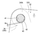
次に、位置調整機構40の挿通ボルト43とナットとの螺合が緩められ、固定ベース34に対する位置調整用ベース32の仮固定が解除される。この状態で、図12に示すように、位置調整用ベース32が固定ベース34に対して下方に引き下げられる。これにより、位置調整用ベース32は、固定ベース34に対してブレーキ25の出力軸251を中心に下方に回動(図6において左回動)し、固定ベース34の挿通ボルト43と位置調整用ベース32の第2ボルト孔42間には下方に隙間Boが形成される。即ち、位置調整用ベース32は、固定ベース34に対する下限位置に保持される。この結果、位置調整用ベース32に設けられたモータ用ピニオンギヤ23pが固定ベース34に対して寸法Bk分だけ下降し、図13に示すように、モータ用ピニオンギヤ23pとラックギヤ22間のバックラッシュが適正値Bkに保持される。
次に、この状態で、位置調整機構40の挿通ボルト43とナットとが適正トルクで締付けられ、位置調整用ベース32と固定ベース34とが連結される。さらに、第1連結機構51、第2連結機構52、及び第3連結機構53により、位置調整用ベース32と固定ベース34とが連結される。これにより、ホルダー148の架台148kに対する歯車支持装置30の取付けが完了する。即ち、モータ用ピニオンギヤ23pが本発明の第1の歯車に相当し、ブレーキ用ピニオンギヤ25pが本発明の第2の歯車に相当する。
<本実施形態に係る歯車支持装置30の長所について>
本実施形態に係る歯車支持装置30によると、位置調整機構40は、モータ用ピニオンギヤ23p(歯車)とラックギヤ22間のバックラッシュの適正値Bk分だけモータ用ピニオンギヤ23pが固定ベース34に対して変位できるように、固定ベース34に対する位置調整用ベース32の回動角度を調整できる。このため、例えば、モータ用ピニオンギヤ23pとラックギヤ22間のバックラッシュが零の状態で固定ベース34をホルダー148の架台148k(基準架台)に固定した後、位置調整機構40により固定ベース34に対する位置調整用ベース32の回動角度を調整してバックラッシュを適正値にできる。即ち、歯車支持装置30の固定ベース34をホルダー148の架台148kに固定した後、位置調整機構40により固定ベース34に対して位置調整用ベース32を回動させてモータ用ピニオンギヤ23pとラックギヤ22間のバックラッシュを適正値にできるため、バックラッシュの調整が容易になる。
本実施形態に係る歯車支持装置30によると、位置調整機構40は、モータ用ピニオンギヤ23p(歯車)とラックギヤ22間のバックラッシュの適正値Bk分だけモータ用ピニオンギヤ23pが固定ベース34に対して変位できるように、固定ベース34に対する位置調整用ベース32の回動角度を調整できる。このため、例えば、モータ用ピニオンギヤ23pとラックギヤ22間のバックラッシュが零の状態で固定ベース34をホルダー148の架台148k(基準架台)に固定した後、位置調整機構40により固定ベース34に対する位置調整用ベース32の回動角度を調整してバックラッシュを適正値にできる。即ち、歯車支持装置30の固定ベース34をホルダー148の架台148kに固定した後、位置調整機構40により固定ベース34に対して位置調整用ベース32を回動させてモータ用ピニオンギヤ23pとラックギヤ22間のバックラッシュを適正値にできるため、バックラッシュの調整が容易になる。
また、位置調整機構40は、挿通ボルト43と第2ボルト孔42との径寸法の差分だけ位置調整用ベース32を固定ベース34に対して回動させる構成のため、位置調整機構40の構成が簡単になる。また、歯車支持装置30が複数の歯車(モータ用ピニオンギヤ23p、ブレーキ用ピニオンギヤ25p)を備えている場合でも各歯車とラックギヤ22間のバックラッシュを適正値にできる。また、固定ベース34は、ホルダー148の架台148k(基準架台)に対して一定範囲で上下方向に回動可能に構成されている。このため、モータ用ピニオンギヤ23pとラックギヤ22、及びブレーキ用ピニオンギヤ25pとラックギヤ22とを噛合させるのが容易になる。また、固定ベース34には、取手部348が設けられているため、固定ベース34をホルダー148の架台148k(基準架台)に対して容易に上下回動させられるようになる。
<変更例>
ここで、本発明は上記実施形態に限定されるものではなく、本発明の要旨を逸脱しない範囲における変更が可能である。例えば、本実施形態では、モータ用ピニオンギヤ23pとブレーキ用ピニオンギヤ25pとを備える歯車支持装置30を例示した。しかし、ブレーキ25、及びブレーキ用ピニオンギヤ25pを省略し、ブレーキ25の出力軸251の代わりに連結軸を使用して固定ベース34と位置調整用ベース32とを相対回動可能な状態で連結する構成でも可能である。また、本実施形態では、第1ボルト孔41と第2ボルト孔42と挿通ボルト43とを備える位置調整機構40について例示した。しかし、例えば、固定ベース34に対して位置調整用ベース32をバックラッシュ分だけずらした状態で位置決め孔に位置決めピンを通す構成の位置調整機構でも可能である。また、本実施形態では、モータ用ピニオンギヤ23p(歯車)等とラックギヤ22間のバックラッシュを適正値に調整する歯車支持装置30を例示した。しかし、本発明の歯車支持装置により、その歯車支持装置の歯車と別の架台に設けられた歯車間のバックラッシュを適正値に調整することも可能である。さらに、歯車支持装置の歯車を二個以上に設けることも可能である。
ここで、本発明は上記実施形態に限定されるものではなく、本発明の要旨を逸脱しない範囲における変更が可能である。例えば、本実施形態では、モータ用ピニオンギヤ23pとブレーキ用ピニオンギヤ25pとを備える歯車支持装置30を例示した。しかし、ブレーキ25、及びブレーキ用ピニオンギヤ25pを省略し、ブレーキ25の出力軸251の代わりに連結軸を使用して固定ベース34と位置調整用ベース32とを相対回動可能な状態で連結する構成でも可能である。また、本実施形態では、第1ボルト孔41と第2ボルト孔42と挿通ボルト43とを備える位置調整機構40について例示した。しかし、例えば、固定ベース34に対して位置調整用ベース32をバックラッシュ分だけずらした状態で位置決め孔に位置決めピンを通す構成の位置調整機構でも可能である。また、本実施形態では、モータ用ピニオンギヤ23p(歯車)等とラックギヤ22間のバックラッシュを適正値に調整する歯車支持装置30を例示した。しかし、本発明の歯車支持装置により、その歯車支持装置の歯車と別の架台に設けられた歯車間のバックラッシュを適正値に調整することも可能である。さらに、歯車支持装置の歯車を二個以上に設けることも可能である。
Claims (5)
- 少なくとも1個の歯車を備えており、基準架台の所定位置に固定されることで、前記歯車を別の架台に設けられたラックギヤ、あるいは別の歯車と噛合させられるように構成された歯車支持装置であって、
前記基準架台に固定される固定ベースと、
前記固定ベースに対して回動可能な状態で連結されている位置調整用ベースと、
前記位置調整用ベースの回動中心から離れた位置で、前記位置調整用ベースに設けられている第1の歯車と、
前記第1の歯車と前記ラックギヤ、あるいは別の歯車間のバックラッシュの適正値分だけ前記第1の歯車が前記固定ベースに対して変位できるように、前記固定ベースに対する前記位置調整用ベースの回動角度を調整可能な位置調整機構と、
を有する歯車支持装置。 - 請求項1に記載された歯車支持装置であって、
前記位置調整機構は、前記固定ベースと前記位置調整用ベースとのいずれか一方に形成された第1ボルト孔と、前記固定ベースと前記位置調整用ベースとのいずれか他方に形成されて、前記第1ボルト孔よりも大径の第2ボルト孔と、前記第1ボルト孔とほぼ等しい径寸法で、前記第1ボルト孔と第2ボルト孔とに通されるボルトとを有しており、
前記ボルトと第2ボルト孔との径寸法差だけ前記位置調整用ベースが前記固定ベースに対して回動することで、前記第1の歯車が前記固定ベースに対してバックラッシュの適正値分だけ変位する歯車支持装置。 - 請求項1又は請求項2のいずれかに記載された歯車支持装置であって、
前記位置調整用ベースの回動中心の位置に第2の歯車が設けられており、
前記第1の歯車と前記ラックギヤ間のバックラッシュが零のときに、前記第2の歯車と前記ラックギヤ間のバックラッシュが適正値となるように、前記第1の歯車と前記第2の歯車との位置関係が設定されている歯車支持装置。 - 請求項1から請求項3のいずれかに記載された歯車支持装置であって、
前記固定ベースは、前記基準架台に対して一定範囲で上下方向に回動可能な状態で仮止めされ、前記第1の歯車が前記ラックギヤ、あるいは別の歯車と噛合した状態で、前記固定ベースは前記基準架台に固定できるように構成されている歯車支持装置。 - 請求項4に記載された歯車支持装置であって、
前記固定ベースには、その固定ベースを基準架台に対して一定範囲で上下方向に回動させる際に把持できる取手部が設けられている歯車支持装置。
Priority Applications (1)
| Application Number | Priority Date | Filing Date | Title |
|---|---|---|---|
| CN201680002524.1A CN106817908B (zh) | 2015-10-02 | 2016-08-17 | 齿轮支承装置 |
Applications Claiming Priority (2)
| Application Number | Priority Date | Filing Date | Title |
|---|---|---|---|
| JP2015-196792 | 2015-10-02 | ||
| JP2015196792A JP6458701B2 (ja) | 2015-10-02 | 2015-10-02 | 歯車支持装置 |
Publications (1)
| Publication Number | Publication Date |
|---|---|
| WO2017056765A1 true WO2017056765A1 (ja) | 2017-04-06 |
Family
ID=58423297
Family Applications (1)
| Application Number | Title | Priority Date | Filing Date |
|---|---|---|---|
| PCT/JP2016/073982 Ceased WO2017056765A1 (ja) | 2015-10-02 | 2016-08-17 | 歯車支持装置 |
Country Status (3)
| Country | Link |
|---|---|
| JP (1) | JP6458701B2 (ja) |
| CN (1) | CN106817908B (ja) |
| WO (1) | WO2017056765A1 (ja) |
Families Citing this family (1)
| Publication number | Priority date | Publication date | Assignee | Title |
|---|---|---|---|---|
| JP7347285B2 (ja) * | 2020-03-23 | 2023-09-20 | トヨタ紡織株式会社 | スライド装置 |
Citations (3)
| Publication number | Priority date | Publication date | Assignee | Title |
|---|---|---|---|---|
| JPS58200857A (ja) * | 1982-05-17 | 1983-11-22 | Fuji Xerox Co Ltd | 治具兼用ラツク |
| JP2001173748A (ja) * | 1999-12-21 | 2001-06-26 | Amada Co Ltd | バックラッシュレス式ラック・ピニオン駆動機構 |
| JP2005035346A (ja) * | 2003-07-17 | 2005-02-10 | Unisia Jkc Steering System Co Ltd | 電動パワーステアリング装置 |
Family Cites Families (6)
| Publication number | Priority date | Publication date | Assignee | Title |
|---|---|---|---|---|
| DE3564667D1 (en) * | 1985-07-02 | 1988-10-06 | Keiper Recaro Gmbh Co | Hinge fitting for seats with an adjustable back rest, particularly for motor vehicle seats |
| KR100410721B1 (ko) * | 2001-04-30 | 2003-12-18 | 현대자동차주식회사 | 버스용 시트 이동장치 |
| JP4950952B2 (ja) * | 2008-07-01 | 2012-06-13 | セイコープレシジョン株式会社 | 駆動装置及び光学機器 |
| CN102724941B (zh) * | 2009-11-26 | 2014-12-17 | 丰田车体株式会社 | 轮椅固定装置 |
| CN102673457A (zh) * | 2011-03-08 | 2012-09-19 | 株式会社塔捷斯 | 相对于座椅架的螺栓固定结构及螺栓的固定方法 |
| CN103481939A (zh) * | 2013-10-10 | 2014-01-01 | 富奥汽车零部件股份有限公司 | 一种齿轮齿条间隙调整机构 |
-
2015
- 2015-10-02 JP JP2015196792A patent/JP6458701B2/ja active Active
-
2016
- 2016-08-17 WO PCT/JP2016/073982 patent/WO2017056765A1/ja not_active Ceased
- 2016-08-17 CN CN201680002524.1A patent/CN106817908B/zh active Active
Patent Citations (3)
| Publication number | Priority date | Publication date | Assignee | Title |
|---|---|---|---|---|
| JPS58200857A (ja) * | 1982-05-17 | 1983-11-22 | Fuji Xerox Co Ltd | 治具兼用ラツク |
| JP2001173748A (ja) * | 1999-12-21 | 2001-06-26 | Amada Co Ltd | バックラッシュレス式ラック・ピニオン駆動機構 |
| JP2005035346A (ja) * | 2003-07-17 | 2005-02-10 | Unisia Jkc Steering System Co Ltd | 電動パワーステアリング装置 |
Also Published As
| Publication number | Publication date |
|---|---|
| CN106817908A (zh) | 2017-06-09 |
| JP6458701B2 (ja) | 2019-01-30 |
| JP2017067264A (ja) | 2017-04-06 |
| CN106817908B (zh) | 2019-03-29 |
Similar Documents
| Publication | Publication Date | Title |
|---|---|---|
| US20180215287A1 (en) | Adjusting device for adjusting a vehicle seat along a sliding axis | |
| CN105403410B (zh) | 车辆的人机主观评价通用平台 | |
| EP2208632A1 (en) | Vehicle seat device | |
| US12005813B2 (en) | Long rail assembly with triple rail configuration | |
| CN101448674A (zh) | 用于座椅调节器的传动装置 | |
| US20070222267A1 (en) | Swinging Apparatus | |
| CN102653248A (zh) | 具有数个调节功能的车辆座椅的电动调节设备的致动器 | |
| KR20130032599A (ko) | 시트쿠션의 높낮이 및 경사 조절구조가 단일화된 차량시트 | |
| JP5655227B2 (ja) | 車両のシート駆動装置 | |
| JP6458701B2 (ja) | 歯車支持装置 | |
| CN106425195B (zh) | 一种工业焊接机器人 | |
| WO2018029919A1 (ja) | 車両用シート | |
| JP5490571B2 (ja) | 車両用シート | |
| JP2008105520A (ja) | 車両用パワーシートの駆動機構 | |
| CN110815158B (zh) | 一种汽车底盘系统检测用的移动装置 | |
| JP2011033043A (ja) | 回転装置 | |
| JP6116330B2 (ja) | 車両のシート装置 | |
| CN104859494A (zh) | 儿童汽车安全座 | |
| KR102950068B1 (ko) | 차량의 암레스트 | |
| JP2013095166A (ja) | 車両用シート | |
| JPS6338046A (ja) | 車両用シ−トのア−ムレスト | |
| CN102555860B (zh) | 车辆用座椅 | |
| JP5596520B2 (ja) | 車両用リフトアップシート | |
| JP2017202264A (ja) | 車椅子収容装置 | |
| CN222496056U (zh) | 一种汽车横梁连接板 |
Legal Events
| Date | Code | Title | Description |
|---|---|---|---|
| 121 | Ep: the epo has been informed by wipo that ep was designated in this application |
Ref document number: 16850941 Country of ref document: EP Kind code of ref document: A1 |
|
| NENP | Non-entry into the national phase |
Ref country code: DE |
|
| 122 | Ep: pct application non-entry in european phase |
Ref document number: 16850941 Country of ref document: EP Kind code of ref document: A1 |