WO2017051889A1 - エンジン - Google Patents
エンジン Download PDFInfo
- Publication number
- WO2017051889A1 WO2017051889A1 PCT/JP2016/078069 JP2016078069W WO2017051889A1 WO 2017051889 A1 WO2017051889 A1 WO 2017051889A1 JP 2016078069 W JP2016078069 W JP 2016078069W WO 2017051889 A1 WO2017051889 A1 WO 2017051889A1
- Authority
- WO
- WIPO (PCT)
- Prior art keywords
- injection
- fuel
- combustion chamber
- cavity
- piston
- Prior art date
- Legal status (The legal status is an assumption and is not a legal conclusion. Google has not performed a legal analysis and makes no representation as to the accuracy of the status listed.)
- Ceased
Links
Images




Classifications
-
- F—MECHANICAL ENGINEERING; LIGHTING; HEATING; WEAPONS; BLASTING
- F02—COMBUSTION ENGINES; HOT-GAS OR COMBUSTION-PRODUCT ENGINE PLANTS
- F02B—INTERNAL-COMBUSTION PISTON ENGINES; COMBUSTION ENGINES IN GENERAL
- F02B23/00—Other engines characterised by special shape or construction of combustion chambers to improve operation
- F02B23/02—Other engines characterised by special shape or construction of combustion chambers to improve operation with compression ignition
- F02B23/06—Other engines characterised by special shape or construction of combustion chambers to improve operation with compression ignition the combustion space being arranged in working piston
- F02B23/0645—Details related to the fuel injector or the fuel spray
- F02B23/0648—Means or methods to improve the spray dispersion, evaporation or ignition
- F02B23/0651—Means or methods to improve the spray dispersion, evaporation or ignition the fuel spray impinging on reflecting surfaces or being specially guided throughout the combustion space
-
- F—MECHANICAL ENGINEERING; LIGHTING; HEATING; WEAPONS; BLASTING
- F02—COMBUSTION ENGINES; HOT-GAS OR COMBUSTION-PRODUCT ENGINE PLANTS
- F02B—INTERNAL-COMBUSTION PISTON ENGINES; COMBUSTION ENGINES IN GENERAL
- F02B23/00—Other engines characterised by special shape or construction of combustion chambers to improve operation
- F02B23/02—Other engines characterised by special shape or construction of combustion chambers to improve operation with compression ignition
- F02B23/06—Other engines characterised by special shape or construction of combustion chambers to improve operation with compression ignition the combustion space being arranged in working piston
- F02B23/0696—W-piston bowl, i.e. the combustion space having a central projection pointing towards the cylinder head and the surrounding wall being inclined towards the cylinder wall
-
- F—MECHANICAL ENGINEERING; LIGHTING; HEATING; WEAPONS; BLASTING
- F02—COMBUSTION ENGINES; HOT-GAS OR COMBUSTION-PRODUCT ENGINE PLANTS
- F02B—INTERNAL-COMBUSTION PISTON ENGINES; COMBUSTION ENGINES IN GENERAL
- F02B23/00—Other engines characterised by special shape or construction of combustion chambers to improve operation
- F02B23/08—Other engines characterised by special shape or construction of combustion chambers to improve operation with positive ignition
- F02B23/10—Other engines characterised by special shape or construction of combustion chambers to improve operation with positive ignition with separate admission of air and fuel into cylinder
- F02B23/101—Other engines characterised by special shape or construction of combustion chambers to improve operation with positive ignition with separate admission of air and fuel into cylinder the injector being placed on or close to the cylinder centre axis, e.g. with mixture formation using spray guided concepts
-
- F—MECHANICAL ENGINEERING; LIGHTING; HEATING; WEAPONS; BLASTING
- F02—COMBUSTION ENGINES; HOT-GAS OR COMBUSTION-PRODUCT ENGINE PLANTS
- F02M—SUPPLYING COMBUSTION ENGINES IN GENERAL WITH COMBUSTIBLE MIXTURES OR CONSTITUENTS THEREOF
- F02M61/00—Fuel-injectors not provided for in groups F02M39/00 - F02M57/00 or F02M67/00
- F02M61/16—Details not provided for in, or of interest apart from, the apparatus of groups F02M61/02 - F02M61/14
- F02M61/18—Injection nozzles, e.g. having valve seats; Details of valve member seated ends, not otherwise provided for
- F02M61/1806—Injection nozzles, e.g. having valve seats; Details of valve member seated ends, not otherwise provided for characterised by the arrangement of discharge orifices, e.g. orientation or size
- F02M61/1813—Discharge orifices having different orientations with respect to valve member direction of movement, e.g. orientations being such that fuel jets emerging from discharge orifices collide with each other
-
- F—MECHANICAL ENGINEERING; LIGHTING; HEATING; WEAPONS; BLASTING
- F02—COMBUSTION ENGINES; HOT-GAS OR COMBUSTION-PRODUCT ENGINE PLANTS
- F02M—SUPPLYING COMBUSTION ENGINES IN GENERAL WITH COMBUSTIBLE MIXTURES OR CONSTITUENTS THEREOF
- F02M61/00—Fuel-injectors not provided for in groups F02M39/00 - F02M57/00 or F02M67/00
- F02M61/16—Details not provided for in, or of interest apart from, the apparatus of groups F02M61/02 - F02M61/14
- F02M61/18—Injection nozzles, e.g. having valve seats; Details of valve member seated ends, not otherwise provided for
- F02M61/1806—Injection nozzles, e.g. having valve seats; Details of valve member seated ends, not otherwise provided for characterised by the arrangement of discharge orifices, e.g. orientation or size
- F02M61/1826—Discharge orifices having different sizes
-
- F—MECHANICAL ENGINEERING; LIGHTING; HEATING; WEAPONS; BLASTING
- F02—COMBUSTION ENGINES; HOT-GAS OR COMBUSTION-PRODUCT ENGINE PLANTS
- F02B—INTERNAL-COMBUSTION PISTON ENGINES; COMBUSTION ENGINES IN GENERAL
- F02B23/00—Other engines characterised by special shape or construction of combustion chambers to improve operation
- F02B23/08—Other engines characterised by special shape or construction of combustion chambers to improve operation with positive ignition
- F02B2023/085—Other engines characterised by special shape or construction of combustion chambers to improve operation with positive ignition using several spark plugs per cylinder
-
- F—MECHANICAL ENGINEERING; LIGHTING; HEATING; WEAPONS; BLASTING
- F02—COMBUSTION ENGINES; HOT-GAS OR COMBUSTION-PRODUCT ENGINE PLANTS
- F02B—INTERNAL-COMBUSTION PISTON ENGINES; COMBUSTION ENGINES IN GENERAL
- F02B23/00—Other engines characterised by special shape or construction of combustion chambers to improve operation
- F02B23/08—Other engines characterised by special shape or construction of combustion chambers to improve operation with positive ignition
- F02B23/10—Other engines characterised by special shape or construction of combustion chambers to improve operation with positive ignition with separate admission of air and fuel into cylinder
- F02B2023/102—Other engines characterised by special shape or construction of combustion chambers to improve operation with positive ignition with separate admission of air and fuel into cylinder the spark plug being placed offset the cylinder centre axis
-
- F—MECHANICAL ENGINEERING; LIGHTING; HEATING; WEAPONS; BLASTING
- F02—COMBUSTION ENGINES; HOT-GAS OR COMBUSTION-PRODUCT ENGINE PLANTS
- F02B—INTERNAL-COMBUSTION PISTON ENGINES; COMBUSTION ENGINES IN GENERAL
- F02B23/00—Other engines characterised by special shape or construction of combustion chambers to improve operation
- F02B23/08—Other engines characterised by special shape or construction of combustion chambers to improve operation with positive ignition
- F02B23/10—Other engines characterised by special shape or construction of combustion chambers to improve operation with positive ignition with separate admission of air and fuel into cylinder
- F02B2023/103—Other engines characterised by special shape or construction of combustion chambers to improve operation with positive ignition with separate admission of air and fuel into cylinder the injector having a multi-hole nozzle for generating multiple sprays
-
- F—MECHANICAL ENGINEERING; LIGHTING; HEATING; WEAPONS; BLASTING
- F02—COMBUSTION ENGINES; HOT-GAS OR COMBUSTION-PRODUCT ENGINE PLANTS
- F02F—CYLINDERS, PISTONS OR CASINGS, FOR COMBUSTION ENGINES; ARRANGEMENTS OF SEALINGS IN COMBUSTION ENGINES
- F02F3/00—Pistons
- F02F3/26—Pistons having combustion chamber in piston head
-
- F—MECHANICAL ENGINEERING; LIGHTING; HEATING; WEAPONS; BLASTING
- F02—COMBUSTION ENGINES; HOT-GAS OR COMBUSTION-PRODUCT ENGINE PLANTS
- F02M—SUPPLYING COMBUSTION ENGINES IN GENERAL WITH COMBUSTIBLE MIXTURES OR CONSTITUENTS THEREOF
- F02M23/00—Apparatus for adding secondary air to fuel-air mixture
- F02M23/04—Apparatus for adding secondary air to fuel-air mixture with automatic control
- F02M23/10—Apparatus for adding secondary air to fuel-air mixture with automatic control dependent on temperature, e.g. engine temperature
-
- F—MECHANICAL ENGINEERING; LIGHTING; HEATING; WEAPONS; BLASTING
- F02—COMBUSTION ENGINES; HOT-GAS OR COMBUSTION-PRODUCT ENGINE PLANTS
- F02M—SUPPLYING COMBUSTION ENGINES IN GENERAL WITH COMBUSTIBLE MIXTURES OR CONSTITUENTS THEREOF
- F02M61/00—Fuel-injectors not provided for in groups F02M39/00 - F02M57/00 or F02M67/00
- F02M61/16—Details not provided for in, or of interest apart from, the apparatus of groups F02M61/02 - F02M61/14
- F02M61/18—Injection nozzles, e.g. having valve seats; Details of valve member seated ends, not otherwise provided for
-
- Y—GENERAL TAGGING OF NEW TECHNOLOGICAL DEVELOPMENTS; GENERAL TAGGING OF CROSS-SECTIONAL TECHNOLOGIES SPANNING OVER SEVERAL SECTIONS OF THE IPC; TECHNICAL SUBJECTS COVERED BY FORMER USPC CROSS-REFERENCE ART COLLECTIONS [XRACs] AND DIGESTS
- Y02—TECHNOLOGIES OR APPLICATIONS FOR MITIGATION OR ADAPTATION AGAINST CLIMATE CHANGE
- Y02T—CLIMATE CHANGE MITIGATION TECHNOLOGIES RELATED TO TRANSPORTATION
- Y02T10/00—Road transport of goods or passengers
- Y02T10/10—Internal combustion engine [ICE] based vehicles
- Y02T10/12—Improving ICE efficiencies
Definitions
- the present invention relates to an engine, and in particular, to an engine that injects fuel directly into a combustion chamber in a cylinder during a predetermined operating range from the latter half of a compression stroke to the first half of an expansion stroke, and performs ignition after compression top dead center. .
- a spark ignition system that uses a spark plug to ignite is widely adopted in an engine using gasoline or fuel mainly composed of gasoline.
- a high compression ratio for example, 14 or more
- gasoline or fuel containing gasoline as a main component is used.
- has developed a technique for performing compression self-ignition specifically, premixed compression self-ignition called HCCI (Homogeneous-Charge Compression) Ignition).
- Patent Document 1 An engine combustion chamber structure configured to perform such compression self-ignition is disclosed in Patent Document 1, for example.
- Patent Document 1 discloses a technique for improving the charging efficiency by configuring the combustion chamber structure applied to the high compression ratio engine so as to sufficiently scavenge the inside of the cavity formed in the central portion of the upper surface of the piston. It is disclosed.
- pre-ignition in order to suppress so-called pre-ignition (pre-ignition), it is between the latter half of the compression stroke and the first half of the expansion stroke. It is necessary to inject fuel from a plurality of nozzle holes of the fuel injection valve, perform forced ignition with a spark plug after compression top dead center, and complete combustion in a short period of time.
- the shape of the path through which the fuel injected from each nozzle moves through the combustion chamber is not uniform, so that spark ignition is performed. Due to the difference in the arrival position of the fuel at the time and the short time from fuel injection to ignition, there is a tendency that a rich portion and a thin portion of the air-fuel mixture are generated in the combustion chamber at the time of spark ignition, that is, There is a tendency that the homogeneity of the air-fuel mixture in the combustion chamber is not ensured.
- the air-fuel mixture containing fuel is discharged without burning, or combustion (afterburning) occurs after the timing to burn, resulting in poor fuel consumption. turn into. In addition, smoke is generated and emissions are also deteriorated.
- the present invention has been made to solve the above-described problems.
- an engine that injects fuel between the latter half of the compression stroke and the first half of the expansion stroke and performs ignition after the compression top dead center the combustion at the ignition timing is performed.
- An object of the present invention is to provide an engine capable of appropriately ensuring the homogeneity of an air-fuel mixture in a room.
- an engine according to the present invention directly injects fuel into a combustion chamber in a cylinder from the latter half of the compression stroke to the first half of the expansion stroke in a predetermined operating region, and after the compression top dead center.
- An engine that performs ignition a piston having a cavity recessed downward in the center of the upper surface, a cylinder head configured to form a pent roof-shaped combustion chamber, and a position corresponding to the center of the piston
- the fuel injection valve is disposed in the cylinder head and injects fuel so as to enter the cavity of the piston between the second half of the compression stroke and the first half of the expansion stroke, and the central portion of the piston corresponding to the position where the fuel injection valve is provided
- a spark plug disposed in the cylinder head at a position radially outside and above the cavity of the piston, and a fuel
- the injection valve has a plurality of injection holes arranged in a circumferential direction surrounding the longitudinal axis of the fuel injection valve and injecting fuel in a direction inclined by a predetermined injection angle from
- the combustion chamber is formed such that the injection angle of the injection port increases as the ceiling height of the combustion chamber at the position corresponding to the edge of the cavity in the injection direction increases.
- the plurality of nozzle holes that are arranged in the circumferential direction surrounding the longitudinal axis of the fuel injection valve and inject fuel in a direction inclined by a predetermined injection angle from the longitudinal axis are The higher the ceiling height of the combustion chamber at the position corresponding to the edge of the cavity in the injection direction, the larger the injection angle of the injection hole, so the edge of the cavity in the injection direction of each injection hole
- the increase in the spray transport path length due to the high ceiling height of the combustion chamber at the position corresponding to the above can be suppressed by expanding the injection angle of the injection port, so that the fuel injected from each injection port Therefore, it is possible to ensure the homogeneity of the air-fuel mixture in the combustion chamber at the ignition timing.
- the injection angle of each injection hole is determined by the spray transport path length which is the length of the path until the fuel injected from each injection nozzle reaches the ceiling of the combustion chamber through the cavity. It is set to be equal to the spray transport path length of the nozzle hole closest to the plug.
- the spray transport path length which is the length of the path until the fuel injected from each injection nozzle reaches the ceiling of the combustion chamber through the cavity. It is set to be equal to the spray transport path length of the nozzle hole closest to the plug.
- the engine of the present invention in the engine that injects fuel during the second half of the compression stroke to the first half of the expansion stroke and ignites after the compression top dead center, it is possible to appropriately ensure the homogeneity of the air-fuel mixture in the combustion chamber. it can.
- FIG. 3 is a partial cross-sectional view of a piston, a cylinder head, and the like according to an embodiment of the present invention, viewed along III-III in FIG. It is the top view which looked at the front-end
- FIG. 5 is a partial cross-sectional view of a tip portion of a fuel injection valve according to an embodiment of the present invention, taken along line VV in FIG. 4.
- FIG. 1 is a schematic plan view of one cylinder of an engine according to an embodiment of the present invention as viewed from below in the cylinder axial direction, and a plurality of fuel injection regions located in the injection direction of each injection port of the fuel injection valve according to the embodiment of the present invention
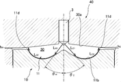
- FIG. FIG. 7 is a partial cross-sectional view of a piston, a cylinder head, etc. according to an embodiment of the present invention, viewed along VII-VII in FIG. 6, and shows fuel injected from each injection port of a fuel injection valve according to an embodiment of the present invention. It is a figure which shows a spray conveyance path
- FIG. 8 is a partial cross-sectional view of a piston and a cylinder head, etc.
- An engine according to an embodiment of the present invention operates at a high compression ratio having a geometric compression ratio of, for example, 14 or more (preferably 18 to 20), and in a predetermined low load region, is premixed called HCCI. It performs compression self-ignition.
- the engine according to the embodiment of the present invention injects fuel from the second half of the compression stroke to the first half of the expansion stroke from the viewpoint of suppressing pre-ignition and the like in a predetermined operation region (for example, low rotation / high load region) ( (Retarded injection) and ignition is performed after compression top dead center.
- a predetermined operation region for example, low rotation / high load region
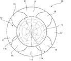
- FIG. 1 is a schematic plan view of one cylinder of an engine according to an embodiment of the present invention viewed from below in the cylinder axial direction
- FIG. 2 is a piston according to the embodiment of the present invention viewed from above in the cylinder axial direction
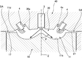
- FIG. 3 is a partial cross-sectional view of a piston, a cylinder head, and the like according to an embodiment of the present invention, viewed along III-III in FIG.
- FIG. 3 shows a view when the piston is located at the compression top dead center.
- the symbol Z indicates a cylinder axis extending in the direction perpendicular to the paper surface
- the symbol Y is a line segment corresponding to the crank axis extending in the vertical direction on the paper surface.
- a combustion chamber is used in which the combustion chamber ceiling on the cylinder head side is formed in a gable roof shape (pent roof shape) (see also FIG. 3).
- the line segment indicated by the symbol Y corresponds to a pent roof-shaped ridge line constituting the combustion chamber (hereinafter referred to as “pent roof ridge line” as appropriate).
- FIG. 3 is a cross-sectional view of a part of a piston, a cylinder head, and the like, cut along a plane along a line segment X orthogonal to the pent roof ridge line Y.
- two cylinders are provided with two intake valves 1 in a region on one side (left side in the figure) across the pent roof ridge line Y.
- the two intake valves 1 are arranged side by side in the pent roof ridgeline Y direction.
- Reference numeral 5 in FIG. 1 indicates an intake port that is opened and closed by the intake valve 1.
- two exhaust valves 2 are disposed in one cylinder on the other side (right side in the drawing) across the pent roof ridge line Y.
- the two exhaust valves 2 are arranged side by side in the pent roof ridgeline Y direction.
- Reference numeral 6 in FIG. 1 denotes an exhaust port that is opened and closed by the exhaust valve 2.
- a single fuel injection valve 3 is disposed on the cylinder axis Z.
- two spark plugs 4 are disposed between the two intake valves 1 and the two exhaust valves 2.
- a cavity 11 recessed downward is formed in the center of the upper surface of the piston 10 (see also FIG. 3).
- the cavity 11 is formed so as to be substantially circular when viewed from the cylinder axis Z direction, and a mountain-shaped protrusion 11a is formed at the center, and the diameter of the protrusion 11a.
- a recessed portion 11b having a height lower than that of the protruding portion 11a is formed on the outer side in the direction so as to surround the protruding portion 11a.
- the fuel injection valve 3 is disposed directly above the protruding portion 11a of the cavity 11, and two spark plugs 4 are disposed in the recess 11b of the cavity 11 (FIGS. 1 and 3). See also).
- annular portion 13 that extends from the outer edge of the cavity 11 to the outer edge of the upper surface of the piston 10 and surrounds the radially outer side of the cavity 11 is provided on the upper portion of the piston 10.
- the annular portion 13 is provided with four valve recesses 15 that are recessed downward, for example, about 1 mm.
- the four valve recesses 15 are provided at positions corresponding to the two intake valves 1 and positions corresponding to the two exhaust valves 2, respectively.
- the portion 17 between each of the four valve recesses 15 is not recessed (that is, the height is higher than the valve recess 15), and is substantially flat.
- the portion 17 between each of the four valve recesses 15 is appropriately referred to as a “piston upper surface portion 17”.
- the fuel injection valve 3 is provided at a location on the cylinder head 40 corresponding to the central portion of the piston 10.
- the longitudinal axis of the fuel injection valve 3 is the cylinder described above.
- the fuel injection valve 3 has a plurality of injection holes 27, and sprays fuel from these injection holes 27 in an umbrella shape about the cylinder axis Z in an axisymmetric manner.
- fuel injected from the latter half of the compression stroke to the first half of the expansion stroke enters the cavity 11 of the piston 10 under the control of the ECU described above.
- the injection angle ⁇ of the fuel from each nozzle 27 is set so as not to collide with the annular portion 13 of the piston 10 or the cylinder side wall (for example, a cylinder liner). Further, in the fuel injection valve 3, the spray collision distance from the fuel injection position to the position where the fuel collides with the cavity 11 is larger than the length (division length) from the fuel injection position to the position where the initial fuel split occurs.
- the injection angle ⁇ is set so that The injection angle ⁇ corresponds to the inclination angle of the fuel injection direction from each injection port 27, which is defined with reference to the longitudinal axis of the fuel injection valve 3 (that is, the cylinder axis Z). Fuel is supplied to the fuel injection valve 3 at a relatively high fuel pressure (for example, 40 MPa to 120 MPa).
- the two spark plugs 4 are respectively provided at locations on the cylinder head 40 that are radially outward from the central portion of the piston 10 and above the cavity 11 of the piston 10. That is, the spark plug 4 is provided at a position such that the electrode 4a at the tip thereof is included in the cavity 11 in the radial direction. Further, the spark plug 4 is disposed so that the electrode 4a is along the combustion chamber ceiling 30a (in other words, the lower surface of the cylinder head 40; the same applies hereinafter). Specifically, the spark plug 4 is provided on the cylinder head 40 so that the electrode 4a portion is inclined to the combustion chamber ceiling 30a while suppressing the protrusion of the electrode 4a to the combustion chamber 30 as much as possible.
- symbol SA has shown the squish area which is the space formed in the clearance gap between the piston upper surface part 17 and the combustion chamber ceiling 30a.
- a squish area SA is not only the clearance between the piston upper surface portion 17 and the combustion chamber ceiling 30a, but also the upper surface of the valve recess 15 (see FIG. 2) provided at a position corresponding to the intake valve 1 and the exhaust valve 2. It is also formed in a gap with the room ceiling 30a.
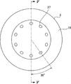
- FIG. 4 is a plan view of the front end portion of the fuel injection valve 3 according to the embodiment of the present invention as viewed from below in the longitudinal axis direction
- FIG. 5 is a view taken along line VV in FIG. It is a fragmentary sectional view of the front-end
- the fuel injection valve 3 includes a bottomed cylindrical valve body extending in the longitudinal axis direction of the fuel injection valve 3, and the fuel injection valve 3 is provided inside the valve body 19.
- a cylindrical needle 21 extending in the longitudinal axis direction is disposed.
- the needle 21 is driven up and down along the longitudinal axis of the fuel injection valve 3 by a highly responsive solenoid (not shown).
- the bottom surface of the valve body 19 is formed in a concave spherical shape that is recessed downward, and a seat portion 23 is formed on the outer peripheral portion of the bottom surface to which the tip of the needle 21 moved downward by a highly responsive solenoid is pressed.
- a space between the inner peripheral surface of the valve body 19 and the outer peripheral surface of the needle 21 is a fuel passage 25.
- a plurality of injection holes 27 are formed on the bottom surface of the valve body on the tip side of the seat portion 23.
- Each injection port 27 is arranged in a circumferential direction surrounding the longitudinal axis of the fuel injection valve 3 and is formed so as to inject fuel in a direction inclined by a predetermined injection angle ⁇ from the longitudinal axis.
- ten injection holes 27 are arranged in the fuel injection valve 3 at equal angular intervals (that is, 36 ° intervals) in the circumferential direction surrounding the longitudinal axis of the fuel injection valve 3. Yes.
- each nozzle hole 27 is formed such that the angle formed by the central axis thereof and the longitudinal axis of the fuel injection valve 3 is ⁇ .
- FIG. 6 is a schematic plan view of one cylinder of the engine according to the embodiment of the present invention viewed from below in the cylinder axial direction, and is positioned in the injection direction of each nozzle 27 of the fuel injection valve 3 according to the embodiment of the present invention. It is a figure which shows the some fuel-injection area
- the combustion chamber 30 at the compression top dead center passes through the middle of each nozzle hole 27 adjacent to each other from the longitudinal axis of the fuel injection valve 3.
- the ten injection holes 27 of the fuel injection valve 3 are represented by symbols A to J, respectively, and the direction in which each injection hole 27 is directed is indicated by a one-dot chain line. That is, the nozzle 27 that is directed upward in FIG.
- a virtual vertical plane P AB extending in the radial direction of the cylinder from the longitudinal axis of the fuel injection valve 3 (that is, the cylinder axis Z) through the middle of the adjacent nozzle holes A and B, and the adjacent nozzle holes J
- a hypothetical vertical plane P JA extending in the radial direction of the cylinder through the middle of the nozzle A and the fuel injection region V A positioned in the injection direction of the nozzle A is divided.
- fuel injection regions V B to V J positioned in the injection direction of the nozzles B to J are divided. As shown in FIG. 6, each of these fuel injection regions is formed in a fan shape in plan view, and is disposed in the circumferential direction surrounding the longitudinal axis of the fuel injection valve 3.
- each injection hole 27 has a larger volume of the fuel injection area located in the injection direction of each injection hole 27.
- the opening area is formed to be large. More preferably, each nozzle hole 27 is formed such that the opening area ratio of each nozzle hole 27 matches the volume ratio of each fuel injection region located in the injection direction of each nozzle hole 27.
- each fuel injection region is divided so as to extend in the pent roof ridge line Y direction in which the height of the fuel injection region (that is, the distance between the upper surface of the piston 10 and the combustion chamber ceiling 30a) is the highest. is the largest volume of the fuel injection region V a and V F, the volume of the pent roof ridge Y segment so as to extend in the direction closest to the line segment X which is perpendicular to the fuel injection region V C, V D, V H , V I Is the smallest. As shown in FIG.
- the nozzle diameter is set so that Specifically, as shown in FIG. 9, the nozzle diameters of the nozzles C, D, H, and I are 0.095 mm, the nozzle diameters of the nozzles B, E, G, and J are 0.100 mm, and the nozzles of the nozzles A and F The aperture is set to 1.3 mm.
- the spray transport path length which is the length of the path until the fuel injected from each nozzle 27 reaches the combustion chamber ceiling 30 a via the cavity 11, is specified.
- the spray transport path length is determined based on the distance from the nozzle 27 of the fuel injection valve 3 to the position where the fuel injected at the injection angle ⁇ collides with the surface of the cavity 11 and the position where the fuel collides with the surface of the cavity 11. It is calculated as the sum of the distance traveled to reach the combustion chamber ceiling 30a via the recess 11b. In the example of FIG.
- the spray transport path length L C of the nozzle C is the distance L C1 from the nozzle C to the position where the fuel injected at the injection angle ⁇ C collides with the surface of the cavity 11, and the fuel of the cavity 11. It is the sum of the travel distance L C2 from the position where it collides with the surface to the combustion chamber ceiling 30a via the recess 11b of the cavity 11, and the spray transport path length L H of the nozzle H is the injection angle from the nozzle H
- the distance L H1 to the position where the fuel injected at ⁇ H collides with the surface of the cavity 11 and the position where the fuel collides with the surface of the cavity 11 reach the combustion chamber ceiling 30a via the recess 11b of the cavity 11. It is the sum with the movement distance LH2 .
- the spray transport path length L A of the nozzle A is a distance L A1 from the nozzle A to the position where the fuel injected at the injection angle ⁇ A collides with the surface of the cavity 11, and the fuel is in the cavity.
- 11 is the sum of the travel distance L A2 from the position of collision with the surface of 11 to the combustion chamber ceiling 30a via the recess 11b of the cavity 11, and the spray transport path length L F of the nozzle F is from the nozzle H
- the distance L F1 to the position where the fuel injected at the injection angle ⁇ F collides with the surface of the cavity 11 and the position where the fuel collides with the surface of the cavity 11 enter the combustion chamber ceiling 30a via the recess 11b of the cavity 11. This is the sum of the movement distance L F2 to reach.
- the height of the combustion chamber ceiling 30a at the position corresponding to the edge part 11d of the cavity 11 in the injection direction of each injection hole 27 increases (that is, the edge part of the cavity 11).
- the spray transport path length becomes shorter as the injection angle ⁇ of the nozzle 27 increases.
- the injection angle of each nozzle hole 27 increases as the height of the combustion chamber ceiling 30a at the position corresponding to the edge 11d of the cavity 11 in the injection direction of each nozzle hole 27 increases.
- the spray transport path length of each nozzle 27 is made equal.
- the edge 11 d of the cavity 11 in the injection direction of the injection holes C, D, H, and I oriented in the direction closest to the line segment X orthogonal to the pent roof ridge line Y in each of the injection holes 27.
- the height of the combustion chamber ceiling 30a at the corresponding position is the lowest, and the height of the combustion chamber ceiling 30a at the position corresponding to the edge 11d of the cavity 11 in the injection direction of the nozzles A and F directed in the pent roof ridge line Y direction. Is the highest. For example, as shown in FIGS.
- the height of the combustion chamber ceiling 30a at the position corresponding to the edge 11d of the cavity 11 in the injection direction of the nozzle C is h C
- the cavity 11 in the injection direction of the nozzle H The height of the combustion chamber ceiling 30a at the position corresponding to the edge end 11d of the combustion chamber is equal to h H , but the height of the combustion chamber ceiling 30a at the position corresponding to the edge end 11d of the cavity 11 in the injection direction of the injection hole A is the h a and the height h F of the combustion chamber ceiling 30a of the position corresponding to the edge portion 11d of the cavity 11 in the injection direction of the injection port F is higher than h C respectively.
- the spray transport path lengths of the nozzles A, C, F, and H are made equal.
- H and h I are set to 0 mm
- the heights h B , h E , h G of the combustion chamber ceiling 30a at positions corresponding to the edge 11d of the cavity 11 in the injection direction of the nozzles B, E, G, J h J is 0.90 mm
- the heights h A and h F of the combustion chamber ceiling 30a at the position corresponding to the edge 11d of the cavity 11 in the injection direction of the nozzles A and F are 2.80 mm.
- the spray transport path lengths L C , L D when the injection angles ⁇ C , ⁇ D , ⁇ H , ⁇ I of the nozzle holes C, D, H, I having the lowest height of the combustion chamber ceiling 30a are 50 °.
- L H and L I are 40 mm.
- the spray transport path length of each nozzle hole 27 is 40 mm, and the spray transport path lengths of all the nozzle holes 27 are equal.
- an engine in which the combustion chamber 30 is formed in a pent roof shape is shown (see FIG. 3 and the like).
- the combustion chamber 30 is not in a pent roof shape (for example, a hemispherical shape or a bathtub shape). It can also be applied to the engine formed in the above.
- the fuel injection valve 3 having ten injection holes 27 is shown.
- the present invention is also applicable to an engine having a fuel injection valve 3 having a plurality of different injection holes 27. Is possible.
- the plurality of nozzle holes 27 arranged in the circumferential direction surrounding the longitudinal axis of the fuel injection valve 3 pass through the combustion chamber 30 at the compression top dead center between the nozzle holes 27 adjacent to each other from the longitudinal axis of the fuel injection valve 3.
- the larger the volume of the fuel injection region located in the injection direction of each injection port 27, the larger the injection port. 27 is formed so that the opening area of the fuel injection chamber 27 is large, even if the volume of the fuel injection region located in the injection direction of each injection hole 27 is different due to the combustion chamber 30 of the engine being formed in a pent roof shape or the like.
- an amount of fuel corresponding to the volume of each fuel injection region can be injected from each injection port 27, thereby ensuring the homogeneity of the air-fuel mixture in the combustion chamber 30 at the ignition timing. That.
- each nozzle hole 27 is formed so that the opening area ratio of each nozzle hole 27 and the volume ratio of each fuel injection region located in the injection direction of each nozzle hole 27 coincide with each other. Therefore, even if the volume of each fuel injection region is different, the air-fuel mixture in each fuel injection region can be made proportional to the volume of each fuel injection region located in the injection direction of each nozzle 27. Therefore, the homogeneity of the air-fuel mixture in the combustion chamber 30 at the ignition timing can be reliably ensured.
- a plurality of injection holes 27 that are arranged in a circumferential direction surrounding the longitudinal axis of the fuel injection valve 3 and inject fuel in a direction inclined by a predetermined injection angle from the longitudinal axis are provided in the cavity 11 in the injection direction of each injection hole 27.
- the edge part of the cavity 11 in the injection direction of each injection hole 27 The increase in the spray transport path length due to the high ceiling height of the combustion chamber 30 at the position corresponding to 11d can be suppressed by increasing the injection angle of the injection holes 27, whereby the fuel injected from each injection hole 27 Can reach the combustion chamber ceiling 30a, and the homogeneity of the air-fuel mixture in the combustion chamber 30 at the ignition timing can be reliably ensured.
- the injection angle of each injection hole 27 is such that the spray transport path length, which is the length of the fuel until the fuel injected from each injection hole 27 reaches the ceiling of the combustion chamber 30 via the cavity 11, is applied to the spark plug 4. Since it is set to be equal to the spray transport path length of the nearest nozzle hole 27, the time when the fuel injected from each nozzle hole 27 reaches the combustion chamber ceiling 30 a is injected from the nozzle hole 27 closest to the spark plug 4. Therefore, it is possible to align the air-fuel mixture containing the fuel to the vicinity of the spark plug 4, thereby ensuring the homogeneity of the air-fuel mixture in the combustion chamber 30 at the ignition timing and also ensuring that the ignition plug 4 is ignitable. Can be secured.
Landscapes
- Engineering & Computer Science (AREA)
- Chemical & Material Sciences (AREA)
- Combustion & Propulsion (AREA)
- Mechanical Engineering (AREA)
- General Engineering & Computer Science (AREA)
- Dispersion Chemistry (AREA)
- Combustion Methods Of Internal-Combustion Engines (AREA)
- Fuel-Injection Apparatus (AREA)
Abstract
Description
このように構成された本発明においては、燃料噴射弁の長手軸線を囲む周方向に配置され且つ長手軸線から所定の噴射角傾斜した方向へ向けて燃料を噴射する複数の噴口は、各噴口の噴射方向におけるキャビティの縁端部に対応する位置の燃焼室の天井高さが高いほど、その噴口の噴射角が大きくなるように形成されているので、各噴口の噴射方向におけるキャビティの縁端部に対応する位置の燃焼室の天井高さが高いことによる噴霧輸送経路長の増大を、噴口の噴射角の拡大により抑制することができ、これにより、各噴口から噴射された燃料が燃焼室天井に到達する時期を揃えることができ、点火時期における燃焼室内の混合気の均質性を確実に確保することができる。
このように構成された本発明においては、各噴口から噴射された燃料が燃焼室天井に到達する時期を、点火プラグに最も近い噴口から噴射された燃料を含む混合気が点火プラグ周辺に到達する時期に揃えることができ、これにより、点火時期における燃焼室内の混合気の均質性を確保しつつ、点火プラグによる着火性も適切に確保することができる。
なお、噴射角θは、燃料噴射弁3の長手軸線(即ちシリンダ軸線Z)を基準にして規定された、各噴口27からの燃料の噴射方向の傾斜角に相当する。また、燃料噴射弁3には、比較的高い燃圧(例えば40MPa~120MPa)にて燃料が供給される。
図6の例では、燃料噴射弁3の10個の噴口27を、それぞれ記号A乃至Jで表すと共に、各噴口27が向けられた方向を一点鎖線で示している。即ち、気筒をシリンダ軸線方向の下方から見てペントルーフ稜線Y方向に沿って図6の紙面上方に向けられた噴口27をAとし、他の噴口27を時計回りにB乃至Jとしている。
そして、燃料噴射弁3の長手軸線(即ちシリンダ軸線Z)から互いに隣接する噴口Aと噴口Bとの中間を通って気筒の径方向に延びる仮想的な垂直面PABと、互いに隣接する噴口Jと噴口Aとの中間を通って気筒の径方向に延びる仮想的な垂直面PJAとにより、噴口Aの噴射方向に位置する燃料噴射領域VAが区分される。同様に、各噴口B乃至Jの噴射方向に位置する燃料噴射領域VB乃至VJが区分される。図6に示すように、これらの各燃料噴射領域は平面視で扇形に形成され、燃料噴射弁3の長手軸線を囲む周方向に配置されている。
噴霧輸送経路長は、燃料噴射弁3の噴口27から噴射角θで噴射された燃料がキャビティ11の表面に衝突する位置までの距離と、燃料がキャビティ11の表面に衝突した位置からキャビティ11の凹部11bを経由して燃焼室天井30aに到達するまでの移動距離との和として求められる。
図7の例では、噴口Cの噴霧輸送経路長LCは、噴口Cから噴射角θCで噴射された燃料がキャビティ11の表面に衝突する位置までの距離LC1と、燃料がキャビティ11の表面に衝突した位置からキャビティ11の凹部11bを経由して燃焼室天井30aに到達するまでの移動距離LC2との和であり、噴口Hの噴霧輸送経路長LHは、噴口Hから噴射角θHで噴射された燃料がキャビティ11の表面に衝突する位置までの距離LH1と、燃料がキャビティ11の表面に衝突した位置からキャビティ11の凹部11bを経由して燃焼室天井30aに到達するまでの移動距離LH2との和である。
また、図8の例では、噴口Aの噴霧輸送経路長LAは、噴口Aから噴射角θAで噴射された燃料がキャビティ11の表面に衝突する位置までの距離LA1と、燃料がキャビティ11の表面に衝突した位置からキャビティ11の凹部11bを経由して燃焼室天井30aに到達するまでの移動距離LA2との和であり、噴口Fの噴霧輸送経路長LFは、噴口Hから噴射角θFで噴射された燃料がキャビティ11の表面に衝突する位置までの距離LF1と、燃料がキャビティ11の表面に衝突した位置からキャビティ11の凹部11bを経由して燃焼室天井30aに到達するまでの移動距離LF2との和である。
そこで、本実施形態では、各噴口27を、各噴口27の噴射方向におけるキャビティ11の縁端部11dに対応する位置の燃焼室天井30aの高さが高いほどその噴口27の噴射角が大きくなるように形成することで、各噴口27の噴霧輸送経路長が等しくなるようにしている。
例えば、図7及び図8に示すように、噴口Cの噴射方向におけるキャビティ11の縁端部11dに対応する位置の燃焼室天井30aの高さをhCと、噴口Hの噴射方向におけるキャビティ11の縁端部11dに対応する位置の燃焼室天井30aの高さをhHとは等しいが、噴口Aの噴射方向におけるキャビティ11の縁端部11dに対応する位置の燃焼室天井30aの高さをhA及び噴口Fの噴射方向におけるキャビティ11の縁端部11dに対応する位置の燃焼室天井30aの高さをhFは、それぞれhCよりも高い。そこで、噴口Cの噴射角θCと噴口Hの噴射角θHを等しくし、噴口Aの噴射角θA及び噴口Hの噴射角θFを、噴口Cの噴射角θCよりも大きくすることで、噴口A、C、F及びHの噴霧輸送経路長が等しくなるようにしている。
また、燃焼室天井30aの高さが最も低い噴口C、D、H、Iの噴射角θC、θD、θH、θIを50°としたときの噴霧輸送経路長LC、LD、LH、LIは40mmである。
この場合、噴口B、E、G、Jの噴射角θB、θE、θG、θJを52°とし、噴口A、Fの噴射角θA、θFを55°とすることにより、各噴口27の噴霧輸送経路長が40mmとなり、全ての噴口27の噴霧輸送経路長が等しくなる。
上記した実施形態では、燃焼室30がペントルーフ形状に形成されたエンジンを示したが(図3等参照)、本発明は、燃焼室30がペントルーフ形状ではない形状(例えば半球型やバスタブ型など)に形成されたエンジンにも適用可能である。
また、上記した実施形態では、10個の噴口27を備えた燃料噴射弁3を示したが、本発明は、これとは異なる複数の噴口27を備えた燃料噴射弁3を有するエンジンにも適用可能である。
2 排気バルブ
3 燃料噴射弁
4 点火プラグ
4a 電極
5 吸気ポート
6 排気ポート
10 ピストン
11 キャビティ
11a 突起部
11b 凹部
11c キャビティの曲面
11d キャビティの縁端部
13 環状部
15 バルブリセス
17 ピストン上面部
19 バルブボディ
21 ニードル
23 シート部
25 燃料通路
27 噴口
30 燃焼室
30a 燃焼室天井
40 シリンダヘッド
Claims (2)
- 所定の運転領域において、圧縮行程後半から膨張行程前半までの間に燃料を気筒内の燃焼室に直接噴射して、圧縮上死点後に点火を行うエンジンであって、
上面の中央部に下方に凹んだキャビティが形成されたピストンと、
ペントルーフ形状の燃焼室を形成するように構成されたシリンダヘッドと、
上記ピストンの中央部に対応する位置において上記シリンダヘッドに配置され、圧縮行程後半から膨張行程前半までの間において上記ピストンのキャビティ内に入るように燃料を噴射する燃料噴射弁と、
上記燃料噴射弁が設けられた位置に対応する上記ピストンの中央部よりも径方向外側で、且つ上記ピストンのキャビティの上方に対応する位置において上記シリンダヘッドに配置された点火プラグと、を有し、
上記燃料噴射弁は、その燃料噴射弁の長手軸線を囲む周方向に配置され且つ上記長手軸線から所定の噴射角傾斜した方向へ向けて燃料を噴射する複数の噴口を有し、
上記各噴口は、上記各噴口の噴射方向における上記キャビティの縁端部に対応する位置の上記燃焼室の天井高さが高いほどその噴口の上記噴射角が大きくなるように形成されている、ことを特徴とするエンジン。 - 上記各噴口の噴射角は、各噴口から噴射された燃料が上記キャビティを介して上記燃焼室の天井に到達するまでの経路の長さである噴霧輸送経路長が、上記点火プラグに最も近い上記噴口の噴霧輸送経路長と等しくなるように設定されている、請求項1に記載のエンジン。
Priority Applications (3)
| Application Number | Priority Date | Filing Date | Title |
|---|---|---|---|
| CN201680054676.6A CN108026880B (zh) | 2015-09-25 | 2016-09-23 | 发动机 |
| DE112016003813.5T DE112016003813B4 (de) | 2015-09-25 | 2016-09-23 | Motor |
| US15/759,495 US10309294B2 (en) | 2015-09-25 | 2016-09-23 | Engine |
Applications Claiming Priority (2)
| Application Number | Priority Date | Filing Date | Title |
|---|---|---|---|
| JP2015-188464 | 2015-09-25 | ||
| JP2015188464A JP6583853B2 (ja) | 2015-09-25 | 2015-09-25 | エンジン |
Publications (1)
| Publication Number | Publication Date |
|---|---|
| WO2017051889A1 true WO2017051889A1 (ja) | 2017-03-30 |
Family
ID=58386793
Family Applications (1)
| Application Number | Title | Priority Date | Filing Date |
|---|---|---|---|
| PCT/JP2016/078069 Ceased WO2017051889A1 (ja) | 2015-09-25 | 2016-09-23 | エンジン |
Country Status (5)
| Country | Link |
|---|---|
| US (1) | US10309294B2 (ja) |
| JP (1) | JP6583853B2 (ja) |
| CN (1) | CN108026880B (ja) |
| DE (1) | DE112016003813B4 (ja) |
| WO (1) | WO2017051889A1 (ja) |
Cited By (1)
| Publication number | Priority date | Publication date | Assignee | Title |
|---|---|---|---|---|
| WO2022201895A1 (ja) * | 2021-03-25 | 2022-09-29 | ヤンマーホールディングス株式会社 | 燃焼室構造及びそれを備えるエンジン |
Families Citing this family (5)
| Publication number | Priority date | Publication date | Assignee | Title |
|---|---|---|---|---|
| JP6229109B1 (ja) * | 2017-04-04 | 2017-11-08 | 康仁 矢尾板 | 4弁式燃焼室 |
| WO2018221638A1 (ja) | 2017-06-02 | 2018-12-06 | マツダ株式会社 | エンジンの燃焼室構造 |
| CN110709593A (zh) | 2017-06-02 | 2020-01-17 | 马自达汽车株式会社 | 发动机的燃烧室结构 |
| FR3071879B1 (fr) * | 2017-09-29 | 2022-03-11 | Ifp Energies Now | Moteur a combustion interne a deux soupapes |
| CN110206655A (zh) * | 2019-05-31 | 2019-09-06 | 钟良 | 一种增大发动机压缩比的活塞以及设计活塞形状方法 |
Citations (2)
| Publication number | Priority date | Publication date | Assignee | Title |
|---|---|---|---|---|
| JP2010144540A (ja) * | 2008-12-16 | 2010-07-01 | Honda Motor Co Ltd | 燃料直噴エンジン |
| JP2014043782A (ja) * | 2012-08-24 | 2014-03-13 | Mazda Motor Corp | エンジンの燃焼室構造 |
Family Cites Families (15)
| Publication number | Priority date | Publication date | Assignee | Title |
|---|---|---|---|---|
| JP3743896B2 (ja) * | 1996-10-31 | 2006-02-08 | 富士重工業株式会社 | 筒内噴射式エンジン |
| DE59806643D1 (de) * | 1998-11-23 | 2003-01-23 | Ford Global Tech Inc | Otto-Brennkraftmaschine mit direkter Kraftstoffeinspritzung |
| JP2002188448A (ja) * | 2000-12-19 | 2002-07-05 | Yamaha Motor Co Ltd | 筒内噴射ガソリンエンジン |
| JP3997781B2 (ja) * | 2002-01-09 | 2007-10-24 | 日産自動車株式会社 | 筒内直噴エンジン |
| DE10350795A1 (de) * | 2003-10-29 | 2005-06-02 | Daimlerchrysler Ag | Direkteinspritzende Brennkraftmaschine |
| DE10354827A1 (de) * | 2003-11-24 | 2005-06-23 | Robert Bosch Gmbh | Brennstoffeinspritzsystem |
| JP4529950B2 (ja) * | 2005-08-25 | 2010-08-25 | 株式会社デンソー | 燃料噴射弁 |
| JP4851864B2 (ja) * | 2006-06-23 | 2012-01-11 | 本田技研工業株式会社 | 燃料直噴ディーゼルエンジン |
| JP4767775B2 (ja) * | 2006-07-04 | 2011-09-07 | 本田技研工業株式会社 | 燃料直噴ディーゼルエンジン |
| JP4447002B2 (ja) * | 2006-12-22 | 2010-04-07 | 本田技研工業株式会社 | 内燃機関 |
| WO2008126771A1 (ja) * | 2007-04-06 | 2008-10-23 | Honda Motor Co., Ltd. | 燃料直噴エンジン |
| JP4732505B2 (ja) * | 2008-04-23 | 2011-07-27 | 本田技研工業株式会社 | 燃料直噴エンジン |
| JP5834829B2 (ja) * | 2011-11-28 | 2015-12-24 | マツダ株式会社 | 火花点火式ガソリンエンジンの制御装置 |
| CN104956043A (zh) * | 2013-01-31 | 2015-09-30 | 丰田自动车株式会社 | 内燃机 |
| JP6020856B2 (ja) * | 2015-01-09 | 2016-11-02 | マツダ株式会社 | エンジンの燃焼室構造 |
-
2015
- 2015-09-25 JP JP2015188464A patent/JP6583853B2/ja active Active
-
2016
- 2016-09-23 DE DE112016003813.5T patent/DE112016003813B4/de not_active Expired - Fee Related
- 2016-09-23 US US15/759,495 patent/US10309294B2/en active Active
- 2016-09-23 WO PCT/JP2016/078069 patent/WO2017051889A1/ja not_active Ceased
- 2016-09-23 CN CN201680054676.6A patent/CN108026880B/zh not_active Expired - Fee Related
Patent Citations (2)
| Publication number | Priority date | Publication date | Assignee | Title |
|---|---|---|---|---|
| JP2010144540A (ja) * | 2008-12-16 | 2010-07-01 | Honda Motor Co Ltd | 燃料直噴エンジン |
| JP2014043782A (ja) * | 2012-08-24 | 2014-03-13 | Mazda Motor Corp | エンジンの燃焼室構造 |
Cited By (2)
| Publication number | Priority date | Publication date | Assignee | Title |
|---|---|---|---|---|
| WO2022201895A1 (ja) * | 2021-03-25 | 2022-09-29 | ヤンマーホールディングス株式会社 | 燃焼室構造及びそれを備えるエンジン |
| JP2022149420A (ja) * | 2021-03-25 | 2022-10-06 | ヤンマーホールディングス株式会社 | 燃焼室構造及びそれを備えるエンジン |
Also Published As
| Publication number | Publication date |
|---|---|
| JP6583853B2 (ja) | 2019-10-02 |
| US20180258884A1 (en) | 2018-09-13 |
| CN108026880B (zh) | 2021-03-26 |
| DE112016003813T5 (de) | 2018-05-24 |
| CN108026880A (zh) | 2018-05-11 |
| US10309294B2 (en) | 2019-06-04 |
| DE112016003813B4 (de) | 2025-05-15 |
| JP2017061907A (ja) | 2017-03-30 |
Similar Documents
| Publication | Publication Date | Title |
|---|---|---|
| JP6583853B2 (ja) | エンジン | |
| JP3353709B2 (ja) | 筒内噴射式火花点火内燃機関 | |
| JP6432788B2 (ja) | エンジンの燃焼室構造 | |
| US9885277B2 (en) | Compression-ignition direct-injection combustion engine and fuel injection method for same | |
| US6742493B2 (en) | Fuel injection system and method for injection | |
| US20190040789A1 (en) | Variable-compression ratio internal-combustion engine with two mixing zones, notably for a motor vehicle, and method of injection for such a vehicule | |
| JP6038339B2 (ja) | 副室式ガスエンジン用のピストンおよび副室式ガスエンジン | |
| US11199155B2 (en) | Piston crown for a combustion system and an associated method thereof | |
| US20160201551A1 (en) | Combustion chamber structure for engine | |
| WO2014188736A1 (ja) | 直噴式ディーゼルエンジン | |
| US6659070B2 (en) | Fuel injection system | |
| KR102097967B1 (ko) | 엔진의 피스톤 연소실구조 | |
| US20200182190A1 (en) | Piston combustion chamber structure of engine | |
| JP6025873B2 (ja) | 特に自動車用の内燃機関及びそのような内燃機関の作動方法 | |
| JP2005155624A (ja) | 燃料噴射システム | |
| JP6694684B2 (ja) | エンジン | |
| JP7643293B2 (ja) | 内燃機関用のスパークプラグ及びこれを備えた内燃機関 | |
| JP2007138780A (ja) | 副室式内燃機関 | |
| WO2021161552A1 (ja) | 副室式エンジン | |
| JP6515942B2 (ja) | 火花点火式内燃機関 | |
| JP4075471B2 (ja) | 筒内直接噴射式内燃機関 | |
| CN216811944U (zh) | 活塞和发动机 | |
| JP7571759B2 (ja) | エンジン | |
| JP7600717B2 (ja) | 内燃機関用のスパークプラグ | |
| WO2024201932A1 (ja) | 副燃焼室付内燃機関 |
Legal Events
| Date | Code | Title | Description |
|---|---|---|---|
| 121 | Ep: the epo has been informed by wipo that ep was designated in this application |
Ref document number: 16848677 Country of ref document: EP Kind code of ref document: A1 |
|
| WWE | Wipo information: entry into national phase |
Ref document number: 15759495 Country of ref document: US |
|
| WWE | Wipo information: entry into national phase |
Ref document number: 112016003813 Country of ref document: DE |
|
| 122 | Ep: pct application non-entry in european phase |
Ref document number: 16848677 Country of ref document: EP Kind code of ref document: A1 |
|
| WWG | Wipo information: grant in national office |
Ref document number: 112016003813 Country of ref document: DE |