WO2021161552A1 - 副室式エンジン - Google Patents
副室式エンジン Download PDFInfo
- Publication number
- WO2021161552A1 WO2021161552A1 PCT/JP2020/025899 JP2020025899W WO2021161552A1 WO 2021161552 A1 WO2021161552 A1 WO 2021161552A1 JP 2020025899 W JP2020025899 W JP 2020025899W WO 2021161552 A1 WO2021161552 A1 WO 2021161552A1
- Authority
- WO
- WIPO (PCT)
- Prior art keywords
- chamber
- sub
- fuel
- partition wall
- recess
- Prior art date
Links
Images


Classifications
-
- F—MECHANICAL ENGINEERING; LIGHTING; HEATING; WEAPONS; BLASTING
- F02—COMBUSTION ENGINES; HOT-GAS OR COMBUSTION-PRODUCT ENGINE PLANTS
- F02B—INTERNAL-COMBUSTION PISTON ENGINES; COMBUSTION ENGINES IN GENERAL
- F02B19/00—Engines characterised by precombustion chambers
- F02B19/10—Engines characterised by precombustion chambers with fuel introduced partly into pre-combustion chamber, and partly into cylinder
-
- F—MECHANICAL ENGINEERING; LIGHTING; HEATING; WEAPONS; BLASTING
- F02—COMBUSTION ENGINES; HOT-GAS OR COMBUSTION-PRODUCT ENGINE PLANTS
- F02B—INTERNAL-COMBUSTION PISTON ENGINES; COMBUSTION ENGINES IN GENERAL
- F02B19/00—Engines characterised by precombustion chambers
- F02B19/12—Engines characterised by precombustion chambers with positive ignition
-
- F—MECHANICAL ENGINEERING; LIGHTING; HEATING; WEAPONS; BLASTING
- F02—COMBUSTION ENGINES; HOT-GAS OR COMBUSTION-PRODUCT ENGINE PLANTS
- F02B—INTERNAL-COMBUSTION PISTON ENGINES; COMBUSTION ENGINES IN GENERAL
- F02B19/00—Engines characterised by precombustion chambers
- F02B19/16—Chamber shapes or constructions not specific to sub-groups F02B19/02 - F02B19/10
-
- Y—GENERAL TAGGING OF NEW TECHNOLOGICAL DEVELOPMENTS; GENERAL TAGGING OF CROSS-SECTIONAL TECHNOLOGIES SPANNING OVER SEVERAL SECTIONS OF THE IPC; TECHNICAL SUBJECTS COVERED BY FORMER USPC CROSS-REFERENCE ART COLLECTIONS [XRACs] AND DIGESTS
- Y02—TECHNOLOGIES OR APPLICATIONS FOR MITIGATION OR ADAPTATION AGAINST CLIMATE CHANGE
- Y02T—CLIMATE CHANGE MITIGATION TECHNOLOGIES RELATED TO TRANSPORTATION
- Y02T10/00—Road transport of goods or passengers
- Y02T10/10—Internal combustion engine [ICE] based vehicles
- Y02T10/12—Improving ICE efficiencies
Definitions
- the present invention relates to a sub-chamber engine provided with a system for igniting the air-fuel mixture in the main chamber by ejecting a flame formed by igniting the air-fuel mixture in the sub-chamber into the main chamber.
- an auxiliary combustion chamber (also referred to as a sub chamber) separated from the main combustion chamber (also referred to as a main chamber) by a partition is provided, and a communication passage connecting these main chamber and the sub chamber to each other is formed in the partition.
- a system also called a jet ignition system
- ignites the air-fuel mixture in the sub-chamber so that the flame formed in the sub-chamber at this time is ejected into the main room through the communication passage to ignite the air-fuel mixture in the main room.
- a sub-chamber engine is known (see, for example, Patent Document 1).
- the fuel supply form of the jet ignition system as described above includes a passive system in which fuel is supplied to the sub-chamber via the main chamber and an active system in which fuel is directly supplied to the sub-chamber.
- FIG. 7 the configuration shown in FIG. 7 was considered as a sub-chamber engine equipped with a passive jet ignition system. That is, as shown in FIG. 7, a partition wall 123 for partitioning the sub chamber 122 is arranged inside in the region including the bore central axis of the upper portion of the main chamber 121 (ceiling wall portion on the cylinder head 103 side), and the main chamber is provided.
- the injector 117 is arranged on the side wall portion 111a of 121.
- a plurality of communication passages 124 communicating the main chamber 121 and the sub chamber 122 are formed in the partition wall 123, and one of the communication passages 124 is used as a fuel supply passage 124a.
- the injector 117 is arranged so that the fuel injection direction is toward the fuel supply path 124a.
- the sub-chamber engine of the present invention includes a main chamber, a sub-chamber partitioned from the main chamber by a partition wall provided on a cylinder head, and a plurality of stations provided on the partition wall and communicating the main chamber and the sub-chamber.
- the passage, the fuel injection valve provided on the wall of the main chamber and injecting fuel into the main chamber, and the fuel injected from the fuel injection valve which is a part of the plurality of passages are described.
- a fuel inflow communication passage to be introduced into the sub-chamber is provided, and a flame formed in the sub-chamber due to ignition of the air-fuel mixture in the sub-chamber is ejected into the main room through the communication passage to inject the flame into the main room.
- a sub-chamber engine that ignites an air-fuel mixture
- the partition wall has a partition wall outer surface that is a surface on the main chamber side and a partition wall inner surface that is a surface on the sub-chamber side, and the fuel inflow on the partition wall outer surface.
- a recess having a receiving surface on which the direct injection fuel from the fuel injection valve collides is formed around the opening of the communication passage, and the intersection of the axial core line of the fuel inflow communication passage and the inner surface of the partition wall is the fuel. It is characterized in that it is on the cylinder head side of the intersection of the axis of the direct-injected fuel from the injection valve and the surface of the inner surface of the partition wall facing the fuel injection valve.
- the fuel inflow passage is inclined from the opening toward the sub-chamber toward the cylinder head side as it approaches the axis of the sub-chamber.
- the recess is formed in a shape that gradually reduces in diameter in the direction from the outside to the inside of the sub chamber.
- the opening is preferably arranged at a position deviated from the center of the receiving surface. In this case, the recess extends in the first direction along the axial direction of the sub chamber, and in the first direction, the distance of one end side portion from one end of the recess to the communication passage and the distance of the recess.
- the distance of the other end side portion from the other end to the communication passage is set to a different size, and in the first direction, the one end side portion and the other end side portion are formed in a curved surface shape having different curvatures. It is preferable that it is.
- the recess extends in a first direction along the axial direction of the sub chamber and a second direction perpendicular to the first direction, and a step in which the fuel injected from the fuel injection valve reaches the recess. It is preferable that the maximum spread width of the fuel in the second direction is set to be smaller than the outer width of the sub chamber in the second direction.
- the fuel injected into the main chamber collides with the receiving surface of the recess on the outer surface of the sub chamber, so that fuel splitting and vaporization can be promoted, and the fuel from the fuel inflow passage to the sub chamber through the recess can be promoted.
- the introduction can be promoted.
- the intersection of the axis of the fuel inflow passage and the inner surface of the sub chamber is closer to the cylinder head than the intersection of the axis of the direct injection fuel and the inner surface of the sub chamber. It becomes easier to introduce fuel near the cylinder head in the sub-chamber.
- FIG. 1A to 1C are views showing the configuration of a combustion chamber of one cylinder of the sub-chamber engine according to the embodiment
- FIG. 1A is a vertical sectional view thereof
- FIG. 1B is a top view thereof
- FIG. 1C is a partition wall thereof. Is an enlarged vertical cross-sectional view.
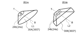
- FIG. 2 is a partial cross-sectional view of the sub-chamber of the sub-chamber engine shown in FIG. 3A and 3B are perspective views showing the shape of a modified example of the recess of the sub-chamber of the sub-chamber engine shown in FIGS. 1A to 1C.
- FIG. 3A shows the first modified example
- FIG. 3B shows the second modified example. A modified example is shown.
- FIGS. 4A to 4C are views showing the shape of a third modification of the recess of the sub chamber of the sub chamber engine shown in FIGS. 1A to 1C
- FIG. 4A is a vertical cross-sectional view of the combustion chamber
- FIG. 4B is a vertical sectional view of the combustion chamber.
- a vertical cross-sectional view of the recess [enlarged view of the main part of FIG. 4A] and FIG. 4C are front views of the recess. It is a cross-sectional view which shows the relationship between the sub chamber of the sub chamber type engine shown in FIGS. 1A to 1C, the concave portion thereof, and a fuel injection range.
- FIGS. 6A to 6C are vertical cross-sectional views of the combustion chamber showing the fuel injection modes of the sub-chamber engine shown in FIGS. 1A to 1C in the order of strokes shown in FIGS. 6A to 6C.
- FIG. 7 is a vertical cross-sectional view of the combustion chamber for explaining the problem of this case.
- the sub-chamber engine (internal combustion engine, including a gasoline engine and a diesel engine; hereinafter, also simply referred to as “engine”) 1 is a multi-cylinder engine, and each cylinder is shown in FIG. 1A.
- the exhaust valve 16 provided in the 15 and the exhaust port 14 is provided.
- two intake ports 13 (15 intake valves) and two exhaust ports 14 (exhaust valves 16) are provided, but the number of intake ports (number of intake valves).
- the number of exhaust ports (the number of exhaust valves) are not limited to this.
- the combustion chamber 20 is partitioned by the inner wall of the cylinder 11, the top surface 12a of the piston 12, and the cylinder head 3.
- An intake port 13 opened and closed by an intake valve 15 and an exhaust port 14 opened and closed by an exhaust valve 16 are connected to the combustion chamber 20 so as to communicate with each other.
- the top of the combustion chamber 20 is formed in a pent roof shape having an intake slope provided with the intake valve 15 and an exhaust slope provided with the exhaust valve 16.
- a fuel injection valve 17 is provided on the peripheral wall 11a at the top of the cylinder 11 (upper part in FIG. 1A). It is configured as a direct injection engine). In the present embodiment, only the fuel injection valve 17 that injects fuel directly into the cylinder 11 is provided, but in addition to this, a fuel injection valve for port injection that injects fuel into the intake port 13 may be added. ..
- the engine according to the present embodiment is a spark-ignition engine, and is located near the bore central axis or the bore central axis at the top (here, the top of the pent roof shape) 20a of the combustion chamber 20 which is a part of the cylinder head 3.
- the combustion chamber 20 is equipped with a spark plug 18 by exposing the spark discharge unit 18a.
- the engine according to this case shall also include a compression ignition engine not provided with a spark plug 16.
- ignition When the air-fuel mixture is ignited by the spark plug 18, it is usually referred to as “igniting”, but here, it is referred to as “igniting” or “igniting” in the sense of including compression ignition.
- the top 20a of the combustion chamber 20 is provided with a partition wall 23 that divides the internal space of the combustion chamber 20 into a main chamber (main combustion chamber) 21 and a sub chamber (sub combustion chamber) 22.
- the partition 23 is arranged so as to cover the space where the spark discharge portion 18a of the spark plug 18 is exposed, and the internal space (the space including the spark discharge portion 18a) covered by the partition 23 in the combustion chamber 20 is the sub chamber 22.
- the external space of the partition wall 23 in the combustion chamber 20 is the main chamber 21.
- the partition wall 23 is formed with a plurality of (seven in this embodiment) communication passages (also referred to as “nozzles”) 24 that communicate the main chamber 21 and the sub chamber 22.
- the plurality of communication passages 24 are a part (here, one) of the plurality of communication passages 24 is a fuel inflow communication passage for introducing the fuel injected into the main chamber 21 from the fuel injection valve 17 into the sub chamber 22. Functions as 24a.
- the fuel injection valve 17 includes an injection port for supplying fuel into the sub chamber 22.
- the ignition plug 18 is used to ignite the air-fuel mixture containing the fuel introduced through the fuel inflow passage 24a at a predetermined timing, and a plurality of flames formed in the sub chamber 22 by this ignition are generated.
- a jet is ejected into the main chamber 21 through the communication passage 24 of the main chamber 21 to ignite the air-fuel mixture in the main chamber 21 and promote combustion.
- Such an ignition system also called a jet ignition system, is effective in igniting a dilute mixture and promoting combustion, and can be applied to lean burn in the main chamber 21 or a large amount of EGR, thereby improving fuel efficiency. Become.
- a concave curved surface 30CF curved along a direction (first direction) D1 along the direction and a direction (second direction) D2 perpendicular to the first direction D1, and a fuel injection valve formed in the concave curved surface 30CF.
- a recess 30 having a receiving surface 30F on which the direct injection fuel from 17 collides is formed.
- the wall surface (inner wall surface) of the recess 30 of the present embodiment includes the concave curved surface 30CF, and the diameter is gradually reduced from the outside to the inside of the sub chamber 22 to form a mortar shape formed by a smooth curved surface.
- the shape of the recess 30 is not limited to this.
- the opening 24b is arranged at or near the bottom of the mortar-shaped recess 30.
- the shaft core line FL2 of the fuel inflow communication passage 24a (that is, the flow path center line of the fuel inflow communication passage 24a) FL2 is different from the shaft core line FL1 of the direct injection fuel from the fuel injection valve 17, and is a secondary of the partition wall 23.
- the intersection P1 with the surface (inner surface of the partition wall) 23b on the chamber 22 side is closer to the cylinder head 3 than the intersection P2 between the axial core line FL1 of the direct injection fuel and the surface of the inner surface 23b of the partition wall facing the fuel injection valve 17. Is formed in.
- the direct injection fuel directly enters the sub chamber 22 through the fuel inflow communication passage 24a. Since the fuel enters, the fuel enters the sub-chamber 22 in a state of insufficient splitting and vaporization, which is disadvantageous for subsequent mixing with air in the sub-chamber 22. However, if the axis FL2 of the fuel inflow communication passage 24a and the axis FL1 of the direct injection fuel from the fuel injection valve 17 do not match, the direct injection fuel directly passes through the fuel inflow communication passage 24a to the sub chamber 22.
- the fuel enters the sub-chamber 22 in a state of being split or vaporized to some extent, and contributes to the subsequent mixing with air in the sub-chamber 22.
- the axis FL2 is not parallel to the axis FL1 (that is, the angles are different), but even if the axis FL2 and the axis FL1 are parallel, the fuel inflow communication passage 24a
- the intersection P1 between the shaft core line FL2 and the inner surface 23b of the partition wall is formed so as to be closer to the cylinder head 3 than the intersection point P2 between the axis core line FL1 of the direct injection fuel and the surface of the inner surface 23b of the partition wall facing the fuel injection valve 17. It suffices if it is done.
- the upper part of the partition wall 23 [the upper part in FIG. 1C (that is, the spark plug side)] is formed in a cylindrical shape
- the lower part of the partition wall 23 [the lower part in FIG. 1C (that is, the piston 12 side)] is formed in a substantially hemispherical shape. It is formed.
- the partition wall 23 is formed in a rotating body shape centered on the position of the spark discharge portion 18a of the spark plug 18 (that is, the position near the bore central axis or the bore central axis), except for a part.
- the shape of the partition wall 23 is not limited to this.
- the upper portion preferably has a cylindrical shape centered on the spark discharge portion 18a of the spark plug 18, but the lower portion may be continuous with the cylindrical shape of the upper portion, and the diameter may be reduced as it goes downward to gradually reduce the cross-sectional area. ..
- the recess 30 is formed on a slope portion deviated from the auxiliary chamber central axis CL in the substantially hemispherical portion below the partition wall 23. Therefore, the lower portion of the partition wall 23 is formed in a substantially hemispherical shape except for the portion where the recess 30 is formed.
- a recess 30 is formed in a part of the lower portion of the partition wall 23 while maintaining a substantially uniform thickness, the recess 30 is formed on the outer surface 23a of the partition wall, and the recess 30 is formed on the inner surface 23b of the partition wall.
- a convex portion 31 corresponding to the above is formed.
- the recess 30 may have a shape in which the outer surface (outer surface of the partition wall) 23a of the sub chamber 22 is cut out.
- the recess 30 is formed on the outer surface 23a of the partition wall while maintaining a substantially hemispherical shape on the inner surface of the partition wall 23. You may. In this case, the thickness of the portion where the recess 30 is formed decreases.
- FIG. 2 is a partial cross-sectional view (a part of a cross section cut along a plane orthogonal to the central axis CL of the sub chamber) at the portion where the recess 30 of the sub chamber 22 is formed, and the recess 30 is shown upward in the drawing for convenience.
- Fuel is injected from the upper part of the figure.
- the shape of the inner wall surface of the recess 30 is gradually reduced in diameter in the direction from the outside to the inside of the sub chamber 22.
- the depth toward the sub-chamber central axis CL gradually becomes shallower from the center CL1 in the cross section of the recess 30 toward the outside.
- the concave portion 30 is oriented along the direction of the sub-chamber central axis CL with respect to the face center (geometric center in the front view) GL [see FIG. 1C] in the front view.
- Both the direction (first direction) D1 and the direction perpendicular to the first direction D1 (second direction) D2 (the direction orthogonal to the sub-chamber central axis CL) are formed in a symmetrical or substantially symmetrical curved shape. ..
- the shape of the wall surface of the recess 30 is not limited to this, and at least the diameter of the sub chamber 22 may be gradually reduced from the outside to the inside.
- a funnel using a conical surface such as a conical surface. It may be in the shape of a (funnel). That is, it may be formed by using a conical surface like the concave portion 30A shown as a modified example in FIG. 3A, or may be formed by using a pyramidal surface like the concave portion 30B shown as a modified example in FIG. 3B.
- the example shown in FIG. 3C uses a quadrangular pyramid surface, but other pyramid surfaces can also be applied.
- a shape including a concave curved surface 30CF curved along the first direction D1 is more preferable.
- the wide side B of the conical surface (corresponding to the opening of the concave portion 30) and the narrow side T of the conical surface (corresponding to the bottom surface portion of the concave portion 30) are It is not limited to a circle or a regular polygon, but may be an ellipse or other polygon. Further, as shown in the recesses 30A and 30B shown in FIGS. 3A and 3B, the lines connecting the center of the wide side B of the conical surface and the center of the narrow side T (L1 and L2 in FIGS. 3A and 3B) are formed.
- the inner surface shape of the frustum inclined with respect to the bottom surface B and the top surface T of the frustum may be applied.
- the recesses 30A and 30B are shown obliquely downward in correspondence with FIGS. 1A and 1B.
- the opening 24b of the fuel inflow passage 24a is arranged at the deepest part (bottom) of the recesses 30A and 30B, but the arrangement of the opening 24b is limited to this. No. Further, the number of openings 24b (the number of fuel inflow communication passages 24a) is not limited to one. A plurality (here, two) openings 24b may be provided as in the recess 30B shown in FIG. 3B. In this case, the direction in which the openings 24b are lined up may be either the first direction D1 or the second direction D2.
- a receiving surface 30F is formed at the center of the fuel injection range from the fuel injection valve 17, and in the present embodiment, the opening 24b is in the first direction along the axial direction of the sub chamber 22, as shown in FIG. 1C. In D1, it is arranged at a position deviated from the center of the fuel injection range from the fuel injection valve 17. In the present embodiment, as shown in FIG. 2, the opening 24b is located at a position substantially along the center of the fuel injection range from the fuel injection valve 17 in the second direction D2 perpendicular to the first direction D1. Have been placed. As a result, the fuel injected from the fuel injection valve 17 does not directly enter the opening 24b, but is once received by the receiving surface 30F and then enters the opening 24b.
- the opening 24b is arranged at a position deviated from the center view center GL of the front view.
- the center of the fuel injection range is slightly shifted downward in FIG. 1C (that is, the piston 12 side) with respect to the front view center GL of the recess 30, and the opening 24b is the front surface of the recess 30. It is slightly shifted upward in FIG. 1C (that is, the cylinder head 3 side) with respect to the visual center GL.
- the direction in which the opening 24b deviates from the center of the fuel injection range is not limited to this.
- the openings 24b may be arranged around the center of the fuel injection range so as to surround the center of the fuel injection range.
- the axis FL2 of the fuel inflow passage 24a is indicated by a chain line, and the axis of the fuel inflow passage 24a is the central axis of the sub chamber 22 in the sub chamber 22 from the opening 24b toward the inside of the sub chamber 22.
- CL the axis of the fuel inflow passage 24a
- the fuel inflow direction in the fuel inflow passage 24a is a direction approaching the spark discharge portion 18a of the upper spark plug 18 in the sub chamber 22.
- the recess 30 extends in the first direction D1 along the axial direction of the sub chamber 22 and in the second direction D2 perpendicular to the first direction D1, but the recess 30 is shown as a modification in FIGS. 4A to 4C.
- the distance (wall length) d2 between d1 and the portion (other end side portion) P2 from the other end of the recess 30 [the upper end in FIGS. 4A to 4C] to the fuel inflow communication passage 24a is different.
- the one end side portion P1 and the other end side portion P2 may be formed in a curved shape having different curvatures.
- the opening 24b of the fuel inflow passage 24a is arranged at a position shifted upward (that is, the cylinder head 3 side) from the front view center GL of the recess 30.
- NS that is, of the distances from the opening 24b to various parts of the peripheral edge of the recess 30, the distance d1 of the one-sided portion P1 having the receiving surface 30F from the opening 24b to one end of the recess 30 is the maximum from the opening 24b.
- the distance d2 of the other end side portion P2 to the other end of the recess 30 is set to the minimum.
- the center of the fuel injection range into the recess 30 is set at a position deviated downward (that is, the piston 12 side) from the front view center GL of the recess 30.
- the curved surface forming the concave portion 30 has a larger curvature 1 / R2 of the other end side portion P2 than the curvature 1 / R1 of the one end side portion P1 having the receiving surface 30F (more). That is, the radius of curvature R2 of the other end side portion P2 is smaller than the radius of curvature R1 of the one end side portion P1).
- the curvature of the one end side portion P1 and the curvature of the other end side portion P2 may be uniform, but the curvature may change partially or entirely, for example, from one end to the other end of the recess 30. It may be formed so that the curvature gradually increases (the radius of curvature decreases).
- the fuel injected from the fuel injection valve 17 gradually diffuses at a predetermined angle ⁇ , but at the stage when the fuel injected from the fuel injection valve 17 reaches the recess 30, the fuel is the first.
- the spread width (maximum spread width) W1 in the two directions D2 is set smaller than the outer width W2 of the sub chamber 22 in the second direction D2 (that is, W2> W1).
- Fuel injection and combustion fuel is injected from the fuel injection valve 17 into the main chamber 21 at the beginning of the intake stroke [see FIG. 6A], and at the end of the subsequent compression stroke, the fuel injection valve 17 enters the sub chamber 22 via the main chamber 21.
- Fuel is injected into (see FIG. 6B).
- port injection port injection is adopted, port injection is performed in the exhaust stroke or the intake stroke, and fuel is supplied to the main chamber 21 together with the intake air in the intake stroke.
- the air-fuel mixture formed in the sub chamber 22 is ignited at the end of the compression stroke, and the flame formed in the sub chamber 22 due to this ignition is jet-sprayed into the main chamber 21 via the plurality of communication passages 24.
- the air-fuel mixture in the main chamber 21 is ignited and burned [see FIG. 6C].
- the injected fuel when fuel is injected from the fuel injection valve 17 into the sub-chamber 22 via the main chamber 21 at the end of the compression stroke, the injected fuel is injected into the opening 24b. It does not enter directly, or is suppressed from entering directly, and collides with the receiving surface 30F in the concave curved surface 30CF of the recess 30 and is received. Therefore, the direct-injection fuel is promoted to split and vaporize while staying in the recess 30 and its vicinity, and then is introduced into the sub-chamber 22 from the opening 24b via the fuel inflow communication passage 24a. The splitting and vaporization of the fuel in the recess 30 contributes to the subsequent promotion of mixing with air in the sub chamber 22. Further, if the fuel directly enters the opening 24b, the fuel may be sufficiently split or vaporized, which is also avoided.
- intersection P1 between the axis FL2 of the fuel inflow communication passage 24a and the inner surface 23b of the partition wall is a cylinder rather than the intersection P2 between the axis FL1 of the direct injection fuel and the surface of the inner surface 23b of the partition wall facing the fuel injection valve 17. Since it is formed so as to be on the head 3 side, it becomes easier to introduce fuel closer to the cylinder head 3 in the sub-chamber 22. That is, it becomes easy to form a fuel-rich air-fuel mixture in the vicinity of the spark discharge portion 18a in the upper part of the sub chamber 22. Therefore, the ignition by the spark plug 18 and the flame formed in the sub chamber 22 thereafter are strengthened.
- the concave curved surface 30CF is the axis of the sub chamber 22. Since it is curved along the first direction D1 along the direction, that is, along the axial direction of the cylinder (direction of the bore central axis), the receiving surface is utilized by utilizing the fluidity of the gas in the cylinder in the cylinder axial direction.
- the direct injection fuel that has collided with the 30F can be guided from the opening 24b to the fuel inflow communication passage 24a along the concave curved surface 30CF.
- the receiving surface 30F is increased.
- the curvature of the end side portion P1 is set to be small, the direct-injection fuel is more promoted to split and vaporize while staying in and near the recess 30, and then in the sub chamber 22. Contributes to promoting mixing with air.
- the direct-injection fuel is caught in the recess 30 and proceeds from the opening 24b to the fuel inflow passage 24a. Therefore, as shown in FIG. 7, a part of the fuel injected from the injector 17 is in the sub chamber 22. It is suppressed that the partition wall 23 (the wall portion of the sub chamber 12) passes along the outer surface without entering the inside, and that it reaches the opposite side of the injector 17 and forms a rich air-fuel mixture is avoided or suppressed. .. Therefore, it is possible to avoid or suppress the generation of a large amount of NOx due to the rich air-fuel mixture.
- the opening 24b of the fuel inflow passage 24a is arranged at the bottom of the recess 30 or near the bottom, the fuel that collides with the receiving surface 30F and is promoted to split or vaporize is placed on the inner wall surface of the recess 30. Along with this, the fuel smoothly flows into the sub chamber 22 from the opening 24b through the fuel inflow passage 24a.
- the fuel inflow communication passage 24a Since the fuel inflow communication passage 24a is inclined in a direction approaching the spark discharge portion 18a of the spark plug 18, the fuel passing through the fuel inflow communication passage 24a goes toward the spark discharge portion 18a in the upper part of the sub chamber 22 and is directed to the spark discharge portion 18a. A rich fuel mixture is concentrated in the vicinity of 18a. Therefore, the ignition by the spark plug 18 and the flame formed in the sub chamber 22 after that can be strengthened, and a strong jet is ejected into the main chamber 21 through the plurality of communication passages 24 to mix in the main chamber 21. It can ignite the qi and promote combustion.
- the fuel injected from the fuel injection valve 17 gradually diffuses at a predetermined angle ⁇ , but the fuel injected from the fuel injection valve 17 reaches the recess 30.
- the spread width W1 in the second direction D2 is set smaller than the outer width W2 of the sub chamber 22 in the second direction D2, and the fuel after the collision passes through the outside of the sub chamber 22 to the exhaust side. It can be suppressed and contributes to the effect of reducing NOx emissions.
- the configuration of the sub-chamber engine described above is an example.
- the arrangement of the sub chamber 22, that is, the partition wall 23 for partitioning the sub chamber 22, is not necessarily limited to the vicinity of the bore central axis CL or the bore central axis CL of the top 20a of the combustion chamber 20, and the top 20a of the combustion chamber 20 is not necessarily limited.
- the fuel injection valve 17 may be provided with an injection port for supplying fuel into the main chamber 21 in addition to an injection port for supplying fuel into the sub chamber 22.
- only one fuel inflow communication passage 24a is provided, but a plurality of fuel inflow communication passages 24a may be provided in the recess 30.
- the concave portion 30 has a mortar shape formed of a smooth curved surface or a funnel shape using a conical surface, but the shape of the concave portion 30 is not limited to this.
- the opening 24b is arranged at the bottom of the recess 30 or near the bottom, but if the shape of the inner surface of the recess 30 is such that the fuel received by the receiving surface 30F can be guided to the opening 24b.
- the opening 24b may be arranged at the bottom of the recess 30 or near the bottom.
Abstract
主室(21)と隔壁(23)で主室(21)と区画された副室(22)と隔壁(23)に設けられた複数の連通路(24)と主室(21)壁部に装備された燃料噴射弁(17)とを備え、副室(22)内の混合気の着火で副室(22)内に形成される火炎を、連通路(24)を介して主室(21)内に噴出させ主室(21)内の混合気に着火する副室式エンジンであり、隔壁(23)は主室(21)側の面である隔壁外面(23a)と副室(22)側の面である隔壁内面(23b)を有し、隔壁外面(23a)の連通路(24a)の開口部(24b)周囲に燃料噴射弁(17)からの直噴燃料が衝突する受面(30a)を有する凹部(30)が形成され、燃料流入連通路(24a)の軸心線と隔壁内面(23b)との交点(P1)が、燃料噴射弁(17)からの直噴燃料の軸心線と隔壁内面(23b)の燃料噴射弁(17)に対向する面との交点(P2)よりもシリンダヘッド側である。
Description
本発明は、副室内で混合気が発火することで形成される火炎を主室内に噴出させて主室内の混合気に点火するシステムを備えた、副室式エンジンに関するものである。
エンジンにおいて、隔壁により主燃焼室(主室ともいう)から分離された副燃焼室(副室ともいう)を設け、これらの主室と副室とを互いに連通する連通路を隔壁に形成し、副室内の混合気を発火させて、このとき副室内に形成される火炎が連通路を介し主室内に噴出するようにして主室内の混合気に点火するシステム(ジェット点火システムともいう)を備えた、副室式エンジンが知られている(例えば、特許文献1参照)。
ところで、上記のようなジェット点火システムの燃料供給形態には、主室を介して副室内に燃料を供給するパッシブ方式のものと、副室内に直接燃料を供給するアクティブ方式のものとがある。
本件の案出過程で、パッシブ方式のジェット点火システムを備えた副室式エンジンとして、図7に示す構成が考えられた。つまり、図7に示すように、主室121の上部(シリンダヘッド103側の天井壁部)のボア中心軸を含む領域に、内部に副室122を区画形成する隔壁123を配置し、主室121の側壁部111aにインジェクタ117を配置する。隔壁123には、主室121と副室122とを連通する複数の連通路124を形成し、連通路124の一つを燃料供給路124aとする。インジェクタ117は、燃料噴射方向がこの燃料供給路124aに向かうように配置する。
このようなパッシブ方式の場合、圧縮行程のタイミングで燃料噴射をすることで副室内に燃料を供給し易くすることができる。しかし、図7に示すように、インジェクタ117から噴射された燃料の一部は、副室122内に進入しないで、隔壁123(副室122の壁部)の外面に沿って通過し、ボア中心軸を挟んでインジェクタ117とは反対側に到達し濃い混合気を形成する。この濃い混合気が量論混合比付近になるとNOxを多く生成してしまうため、課題となっている。
本件は、このような課題に着目して創案されたもので、パッシブ方式のジェット点火システムを備えた副室式エンジンにおいて、副室内の特にシリンダヘッド近くに燃料を導入しやすくして、NOxの生成を抑制できるようにすることを目的の一つとしている。なお、この目的に限らず、後述する発明を実施するための形態に示す各構成により導かれる作用効果であって、従来の技術によっては得られない作用効果を奏することも本件の他の目的である。
本件の副室式エンジンは、主室と、シリンダヘッドに設けられた隔壁により前記主室と区画された副室と、前記隔壁に設けられ前記主室と前記副室とを連通する複数の連通路と、前記主室の壁部に装備され、前記主室内に燃料を噴射する燃料噴射弁と、複数の前記連通路のうちの一部であって前記燃料噴射弁から噴射された燃料を前記副室内に導入する燃料流入連通路と、を備え、前記副室内の混合気の着火により前記副室内に形成される火炎を、前記連通路を介して前記主室内に噴出させて前記主室内の混合気に着火する、副室式エンジンであって、前記隔壁は、前記主室側の面である隔壁外面と前記副室側の面である隔壁内面を有し、前記隔壁外面における前記燃料流入連通路の開口部の周囲に前記燃料噴射弁からの直噴燃料が衝突する受面とを有する凹部が形成され、前記燃料流入連通路の軸心線と前記隔壁内面との交点が、前記燃料噴射弁からの直噴燃料の軸心線と前記隔壁内面の前記燃料噴射弁に対向する面との交点よりも前記シリンダヘッド側であることを特徴としている。
前記燃料流入連通路は前記開口部から前記副室内に向けて前記副室内の軸心に近づくほど前記シリンダヘッド側に向かうように傾斜していることが好ましい。
前記凹部は、前記副室の外部から内部へ向かう方向に次第に縮径する形状に形成されていることが好ましい。
前記開口部は、前記受面の中心からずれた位置に配置されていることが好ましい。
この場合、前記凹部は、前記副室の軸方向に沿った第1方向に延在し、前記第1方向において、前記凹部の一端から前記連通路までの一端側部分の距離と、前記凹部の他端から前記連通路までの他端側部分の距離とが、異なる大きさに設定され、前記第1方向において、前記一端側部分と前記他端側部分とは、曲率の異なる曲面状に形成されていることが好ましい。
前記凹部は、前記副室の軸方向に沿った第1方向と、前記第1方向と直角な第2方向とに延在し、前記燃料噴射弁から噴射される燃料が前記凹部に到達する段階での当該燃料の前記第2方向への最大広がり幅は、前記副室の前記第2方向への外形幅よりも小さく設定されていることが好ましい。
本件によれば、主室内に噴射された燃料が副室の外側面の凹部の受面に衝突するため、燃料の分裂や気化を促進でき、凹部を通じて、燃料流入連通路から副室内への燃料導入を促進できる。また、燃料流入連通路の軸心線と副室の内側面との交点が、直噴燃料の軸心線と副室の内側面との交点よりもシリンダヘッド側となるようにしているため、副室内のシリンダヘッド近くに燃料を導入しやすくなる。
以下、図面を参照して、実施形態としての副室式エンジンについて説明する。以下に示す実施形態はあくまでも例示に過ぎず、以下の実施形態で明示しない種々の変形や技術の適用を排除する意図はない。本実施形態の各構成は、それらの趣旨を逸脱しない範囲で種々変形して実施することができる。また、必要に応じて取捨選択することができ、あるいは適宜組み合わせることができる。
[全体構成]
本実施形態に係る副室式エンジン(内燃機関であって、ガソリンエンジンやディーゼルエンジンを含む。以下、単に「エンジン」ともいう)1は、多気筒エンジンであり、各気筒は、図1Aに示すように、シリンダブロック2に形成されたシリンダ11と、シリンダ11内を往復動するピストン12と、シリンダヘッド3に形成された吸気ポート13及び排気ポート14と、吸気ポート13に装備された吸気弁15及び排気ポート14に装備された排気弁16を備えている。
なお、本実施形態では、図1Bに示すように、吸気ポート13(吸気弁15)及び排気ポート14(排気弁16)はいずれも2つずつ装備されているが、吸気ポート数(吸気弁数)及び排気ポート数(排気弁数)はこれに限定されるものではない。
シリンダ11内のシリンダヘッド3側(図中上部)には、シリンダ11の内壁とピストン12の頂面12aと、シリンダヘッド3とによって、燃焼室20が区画形成されている。燃焼室20には、吸気弁15で開閉される吸気ポート13及び排気弁16で開閉される排気ポート14が連通可能に接続されている。なお、ここでは、燃焼室20の頂部は、吸気弁15が設けられた吸気斜面と排気弁16が設けられた排気斜面とを有するペントルーフ形状に形成されている。
シリンダ11内の頂部(図1A中の上部)の周壁11aには、燃料噴射弁17が装備されており、本実施形態のエンジンは1、シリンダ11内に直接燃料を噴射する筒内噴射エンジン(直噴エンジン)として構成されている。本実施形態では、シリンダ11内に直接燃料噴射する燃料噴射弁17のみを備えているが、これに加えて、吸気ポート13に燃料を噴射するポート噴射用の燃料噴射弁を追加してもよい。
本実施形態に係るエンジンは、火花点火式エンジンであり、シリンダヘッド3の一部である燃焼室20の頂部(ここでは、ペントルーフ形状の頂部)20aにおいて、ボア中心軸又はボア中心軸の近傍に、燃焼室20に火花放電部18aを露出させて点火プラグ18が装備されている。ただし、本件に係るエンジンは、点火プラグ16を備えない圧縮着火エンジンをも含むものとする。なお、点火プラグ18により混合気を着火する場合、通常は「点火する」というが、ここでは、圧縮着火も含める意味で、「着火する」、又は「発火させる」という。
[主室及び副室の構成]
燃焼室20の頂部20aには、燃焼室20の内部空間を、主室(主燃焼室)21と、副室(副燃焼室)22とに区画する隔壁23が装備されている。この隔壁23は、点火プラグ18の火花放電部18aが露出する空間を覆うように配置され、燃焼室20内の隔壁23で覆われる内部空間(火花放電部18aを含む空間)が副室22となっており、燃焼室20内の隔壁23の外部空間が主室21となっている。
燃焼室20の頂部20aには、燃焼室20の内部空間を、主室(主燃焼室)21と、副室(副燃焼室)22とに区画する隔壁23が装備されている。この隔壁23は、点火プラグ18の火花放電部18aが露出する空間を覆うように配置され、燃焼室20内の隔壁23で覆われる内部空間(火花放電部18aを含む空間)が副室22となっており、燃焼室20内の隔壁23の外部空間が主室21となっている。
図1Cに示すように、隔壁23には、主室21と副室22とを連通する複数(本実施形態では7個)の連通路(「ノズル」ともいう)24が形成されている。複数の連通路24は、複数の連通路24の一部(ここでは1つ)は、燃料噴射弁17から主室21内に噴射された燃料を副室22に導入するための燃料流入連通路24aとして機能する。
燃料噴射弁17は、副室22内に燃料供給するための噴射口を備えている。
燃料噴射弁17は、副室22内に燃料供給するための噴射口を備えている。
副室22内では、燃料流入連通路24aを通じて導入された燃料を含んだ混合気に所定のタイミングで点火プラグ18を用いて着火し、この着火により副室22内に形成される火炎を、複数の連通路24を介して主室21内にジェット噴出させて主室21内の混合気に点火し、燃焼を促進する。このような点火システムは、ジェット点火システムとも呼ばれ、希薄混合気への点火及び燃焼促進に有効であり、主室21内のリーンバーンや大量EGR時に適用でき、これにより、燃費向上が可能になる。
ところで、隔壁23の主室21側の面(隔壁外面)23aにおいて、燃料流入連通路24aが開口する開口部24bの周囲には、主室21及び副室22が形成される副室22の軸方向に沿った方向(第1方向)D1、及び、第1方向D1と直角な方向(第2方向)D2に沿って湾曲した凹状湾曲面30CFと、凹状湾曲面30CF内に形成され燃料噴射弁17からの直噴燃料が衝突する受面30Fとを有する凹部30が形成されている。本実施形態の凹部30の壁面(内壁面)は、凹状湾曲面30CFを含み、副室22の外部から内部に向かって次第に縮径し、滑らかな曲面で形成されたすり鉢形状に形成されているが、凹部30の形状はこれに限定されるものではない。開口部24bは、すり鉢形状の凹部30の底部又は底部近傍に配置されている。
また、燃料流入連通路24aの軸心線(即ち、燃料流入連通路24aの流路中心線)FL2は、燃料噴射弁17からの直噴燃料の軸心線FL1と異なるとともに、隔壁23の副室22側の面(隔壁内面)23bとの交点P1が、直噴燃料の軸心線FL1と隔壁内面23bの燃料噴射弁17に対向する面との交点P2よりもシリンダヘッド3側となるように形成されている。燃料流入連通路24aの軸心線FL2が燃料噴射弁17からの直噴燃料の軸心線FL1と一致又はほぼ一致すると、直噴燃料が燃料流入連通路24aを通じて直接的に副室22内に進入するため、燃料が分裂や気化が不足した状態で副室22内に進入し、その後の副室22での空気との混合に不利になる。しかし、燃料流入連通路24aの軸心線FL2と燃料噴射弁17からの直噴燃料の軸心線FL1とを一致させなければ、直噴燃料が燃料流入連通路24aを通じて直接的に副室22内に進入することが抑制され、燃料が少なからず分裂や気化した状態で副室22内に進入し、その後の副室22での空気との混合に寄与する。なお、ここでは、軸心線FL2は軸心線FL1と平行でない(つまり角度が異なっている)が、軸心線FL2と軸心線FL1とが平行であっても、燃料流入連通路24aの軸心線FL2と隔壁内面23bとの交点P1が、直噴燃料の軸心線FL1と隔壁内面23bの燃料噴射弁17に対向する面との交点P2よりもシリンダヘッド3側となるように形成されていればよい。
本実施形態では、隔壁23の上部〔図1Cにおける上部(即ち、点火プラグ側)〕は円筒形状に形成され、隔壁23の下部〔図1Cにおける下部(即ち、ピストン12側)は略半球形状に形成されている。また、隔壁23は、一部を除いて、点火プラグ18の火花放電部18aの位置(即ち、ボア中心軸又はボア中心軸の近傍の位置)を中心とする回転体形状に形成されている。ただし、隔壁23の形状はこれに限定されない。上部は点火プラグ18の火花放電部18aを中心とした円筒形状が好ましいが、下部は上部の円筒形状と連続し、下方に行くにしたがって縮径して次第に横断面積が小さくなる形状であればよい。
[副室の凹部の構成]
本実施形態では、凹部30は、隔壁23の下部の略半球形状の部分における副室中心軸CLからずれた斜面部に形成されている。したがって、凹部30が形成される部分を除いて、隔壁23の下部は略半球形状に形成されている。
本実施形態では、凹部30は、隔壁23の下部の略半球形状の部分における副室中心軸CLからずれた斜面部に形成されている。したがって、凹部30が形成される部分を除いて、隔壁23の下部は略半球形状に形成されている。
また、本実施形態では、隔壁23の下部の一部を、厚みをほぼ均一に保ちながら凹部30を形成しており、隔壁外面23aに凹部30が形成されると共に、隔壁内面23bには凹部30と対応した凸部31が形成されている。ただし、凹部30は、副室22の外側面(隔壁外面)23aを切り欠いた形状であればよく、例えば、隔壁23の内面は略半球形状を保ったまま、隔壁外面23aに凹部30を形成してもよい。この場合、凹部30を形成する箇所は厚みが減少する。
図2は副室22の凹部30が形成された箇所における部分横断面図(副室中心軸CLと直交する面で切った断面の一部)であり、便宜上、凹部30を図中上向きに記載しており、図中上方にから燃料が噴射される。図2に矢印A1~A3で示すように、凹部30の内壁面の形状は、ここでは、副室22の外部から内部に向かう方向に次第に径が縮小している。換言すれば、図2に矢印A4~A7で示すように、凹部30の横断面における中心CL1から外側に向かって、副室中心軸CLに向かう深さが次第に浅くなっている。
本実施形態では、図1C及び図2に示すように、凹部30の正面視における面心(正面視の幾何中心)GL〔図1C参照〕に対して、副室中心軸CLの方向に沿った方向(第1方向)D1にも、第1方向D1と直角な方向(第2方向)D2(副室中心軸CLと直交する方向)にも、対称又はほぼ対称の曲面形状に形成されている。
ただし、凹部30の壁面の形状はこれに限定されるものではなく、少なくとも副室22の外部から内部に向かって次第に縮径していればよく、例えば、円錐面等の錐面を用いたファンネル(漏斗)形状であってもよい。つまり、図3Aに変形例として示す凹部30Aのように、円錐面を用いて形成してもよく、図3Bに変形例として示す凹部30Bのように、角錐面を用いて形成してもよい。図3Cに示す例は、四角錐面を用いているが、これ以外の角錐面も適用できる。また、第1方向D1に沿って湾曲した凹状湾曲面30CFを含む形状であればより好ましい。
また、凹部30の壁面の形状に錐面を用いる場合も、錐面の幅広側B(凹部30の開口に相当する)や錐面の幅狭側T(凹部30の底面部に相当する)は円や正多角形に限らず、楕円やその他の多角形であってもよい。
さらに、図3A,図3Bに示す凹部30A,30Bのように、錐面の幅広側Bの中心と幅狭側Tの中心とを結ぶ線(図3A,図3B中のL1,L2)が、錐台の底面Bや頂面Tに対して傾斜した錐台(即ち、底面Bに対して頂面Tが横ズレした錐台)の内面形状を適用してもよい。図3A,図3Bでは、図1A,図1Bに対応させて、凹部30A,30Bを斜め下向きに記載している。
さらに、図3A,図3Bに示す凹部30A,30Bのように、錐面の幅広側Bの中心と幅狭側Tの中心とを結ぶ線(図3A,図3B中のL1,L2)が、錐台の底面Bや頂面Tに対して傾斜した錐台(即ち、底面Bに対して頂面Tが横ズレした錐台)の内面形状を適用してもよい。図3A,図3Bでは、図1A,図1Bに対応させて、凹部30A,30Bを斜め下向きに記載している。
なお、図3A,図3Bに示す変形例では、凹部30A,30Bの最深部(底部)に、燃料流入連通路24aの開口部24bが配置されているが、開口部24bの配置はこれに限らない。また、開口部24bの数(燃料流入連通路24aの数)も1つだけに限定されない。図3Bに示す凹部30Bのように、開口部24bを複数(ここでは2つ)設けてもよい。この場合の、開口部24bの並ぶ方向は、第1方向D1でも第2方向D2でもよい。
燃料噴射弁17からの燃料噴射範囲の中心に受面30Fが形成されており、本実施形態では、開口部24bは、図1Cに示すように、副室22の軸方向に沿った第1方向D1において、燃料噴射弁17からの燃料噴射範囲の中心からずれた位置に配置されている。なお、本実施形態では、開口部24bは、図2に示すように、第1方向D1と直角な第2方向D2においては、燃料噴射弁17からの燃料噴射範囲の中心にほぼ沿った位置に配置されている。これによって、燃料噴射弁17から噴射された燃料は、開口部24bに直接進入せずに、一旦、受面30Fで受け止められた後に、開口部24bに進入するようになっている。
燃料噴射範囲の中心が、凹部30の正面視における中心(正面視の幾何中心)GLにある場合は、開口部24bはこの正面視中心GLからずれた位置に配置される。本実施形態では、燃料噴射範囲の中心は、凹部30の正面視中心GLに対して、図1Cにおける下方(即ち、ピストン12側)にややシフトしており、開口部24bは、凹部30の正面視中心GLに対して、図1Cにおける上方(即ち、シリンダヘッド3側)にややシフトしている。燃料噴射範囲の中心に対して開口部24bがずれる方向はこの限りではない。例えば、図3Bに示すように、開口部24bを複数設ける場合には、燃料噴射範囲の中心の周囲に、燃料噴射範囲の中心を囲むように開口部24bを配置してもよい。
また、燃料流入連通路24aの軸心線FL2を一点鎖線で示すが、燃料流入連通路24aの軸心線は、開口部24bから副室22内に向けて副室22内の副室中心軸CLに近づくほど、図1Cにおける上方(即ち、シリンダヘッド3側)に向かうように傾斜している。この燃料流入連通路24aにおける燃料の流入方向は、副室22内の上部の点火プラグ18の火花放電部18aに近づく方向である。
なお、凹部30は、副室22の軸方向に沿った第1方向D1と、第1方向D1と直角な第2方向D2とに延在するが、図4A~図4Cに変形例として示す凹部30Cのように、第1方向D1において、凹部30の一端〔図4A~図4C中、下方の端〕から燃料流入連通路24aまでの部分(一端側部分)P1の距離(壁面の長さ)d1と、凹部30の他端〔図4A~図4C中、上方の端〕から燃料流入連通路24aまでの部分(他端側部分)P2の距離(壁面の長さ)d2とが、異なる大きさに設定され、且つ、第1方向D1において、一端側部分P1と他端側部分P2とは、曲率の異なる曲面状に形成されていてもよい。
この変形例では、図4B,図4Cに示すように、燃料流入連通路24aの開口部24bは、凹部30の正面視中心GLから上方(即ち、シリンダヘッド3側)にずれた位置に配置される。つまり、開口部24bから凹部30の周縁部の各所までの距離のうち、開口部24bから凹部30の一端までの、受面30Fを有する一端側部分P1の距離d1が最大に、開口部24bから凹部30の他端までの、他端側部分P2の距離d2が最小に、設定されている。
また、凹部30内への燃料噴射範囲の中心は、凹部30の正面視中心GLから下方(即ち、ピストン12側)にずれた位置に設定される。
また、図4Bに示すように、凹部30を形成する曲面は、受面30Fを有する一端側部分P1の曲率1/R1に比べて、他端側部分P2の曲率1/R2の方が大きく(即ち、一端側部分P1の曲率半径R1よりも他端側部分P2の曲率半径R2の方が小さく)形成されている。なお、一端側部分P1の曲率及び他端側部分P2の曲率は、それぞれが均一でもよいが、部分的に又は全体的に曲率が変化してもよい、例えば、凹部30の一端から他端に向かって次第に曲率が大きくなる(曲率半径が小さくなる)ように形成してもよい。
また、図4Bに示すように、凹部30を形成する曲面は、受面30Fを有する一端側部分P1の曲率1/R1に比べて、他端側部分P2の曲率1/R2の方が大きく(即ち、一端側部分P1の曲率半径R1よりも他端側部分P2の曲率半径R2の方が小さく)形成されている。なお、一端側部分P1の曲率及び他端側部分P2の曲率は、それぞれが均一でもよいが、部分的に又は全体的に曲率が変化してもよい、例えば、凹部30の一端から他端に向かって次第に曲率が大きくなる(曲率半径が小さくなる)ように形成してもよい。
図5に示すように、燃料噴射弁17から噴射される燃料は、所定の角度αで徐々に拡散するが、燃料噴射弁17から噴射される燃料が凹部30に到達する段階における、燃料の第2方向D2への広がり幅(最大広がり幅)W1は、副室22の第2方向D2への外形幅W2よりも小さく(即ち、W2>W1に)設定されている。
[燃料噴射及び燃焼]
本実施形態では、吸気行程初期に燃料噴射弁17から主室21内に燃料が噴射され〔図6A参照〕、その後の圧縮行程終期に燃料噴射弁17から主室21を介して副室22内に燃料が噴射される〔図6B参照〕。なお、ポート噴射を採用する場合は、排気行程もしくは吸気行程においてポート噴射を実施し、吸気行程において吸気と共に燃料を主室21内に供給する。そして、圧縮行程末期に副室22内に形成された混合気に着火して、この着火により副室22内に形成される火炎を、複数の連通路24を介して主室21内にジェット噴出させて主室21内の混合気に点火し、燃焼させる〔図6C参照〕。
本実施形態では、吸気行程初期に燃料噴射弁17から主室21内に燃料が噴射され〔図6A参照〕、その後の圧縮行程終期に燃料噴射弁17から主室21を介して副室22内に燃料が噴射される〔図6B参照〕。なお、ポート噴射を採用する場合は、排気行程もしくは吸気行程においてポート噴射を実施し、吸気行程において吸気と共に燃料を主室21内に供給する。そして、圧縮行程末期に副室22内に形成された混合気に着火して、この着火により副室22内に形成される火炎を、複数の連通路24を介して主室21内にジェット噴出させて主室21内の混合気に点火し、燃焼させる〔図6C参照〕。
[作用及び効果]
本実施形態に係る副室式エンジンによれば、圧縮行程終期に燃料噴射弁17から主室21を介して副室22内に燃料が噴射されると、噴射された燃料は、開口部24bに直接進入することなく、或いは、直接進入することが抑制されて、凹部30の凹状湾曲面30CF内の受面30Fに衝突して受け止められる。このため、直噴燃料は、凹部30内及びその近傍で滞留しながら分裂や気化を促進され、その後、開口部24bから燃料流入連通路24aを経て副室22内へ導入される。この凹部30内での燃料の分裂や気化は、その後の副室22での空気との混合促進に寄与する。また、燃料が開口部24bに直接進入すると、燃料の分裂や気化が不十分になるおそれがあるが、これも回避される。
本実施形態に係る副室式エンジンによれば、圧縮行程終期に燃料噴射弁17から主室21を介して副室22内に燃料が噴射されると、噴射された燃料は、開口部24bに直接進入することなく、或いは、直接進入することが抑制されて、凹部30の凹状湾曲面30CF内の受面30Fに衝突して受け止められる。このため、直噴燃料は、凹部30内及びその近傍で滞留しながら分裂や気化を促進され、その後、開口部24bから燃料流入連通路24aを経て副室22内へ導入される。この凹部30内での燃料の分裂や気化は、その後の副室22での空気との混合促進に寄与する。また、燃料が開口部24bに直接進入すると、燃料の分裂や気化が不十分になるおそれがあるが、これも回避される。
さらに、燃料流入連通路24aの軸心線FL2と隔壁内面23bとの交点P1が、直噴燃料の軸心線FL1と隔壁内面23bの燃料噴射弁17に対向する面との交点P2よりもシリンダヘッド3側となるように形成されているので、燃料をより副室内22のシリンダヘッド3の近くに導入しやすくなる。つまり、副室22上部の火花放電部18aに近傍に集中的に燃料の濃い混合気を形成しやすくなる。このため、点火プラグ18による点火及びその後副室22内に形成される火炎が強化される。
また、副室22の軸方向(副室中心軸CLの方向)がボア中心軸の軸方向(気筒の軸方向)と一致している場合には、凹状湾曲面30CFは、副室22の軸方向に沿った第1方向D1、即ち、気筒の軸方向(ボア中心軸の方向)に沿って湾曲しているので、気筒内の気体の気筒軸方向への流動性を利用して、受面30Fに衝突した直噴燃料を、凹状湾曲面30CFに沿って開口部24bから燃料流入連通路24aに案内することができる。
また、図4Cに示すように、副室22の軸方向に沿った第1方向D1において、受面30Fを有する一端側部分P1の距離d1が最大に設定されていると、受面30Fを大きくとれ、且つ、この端側部分P1の曲率が小さく設定されていると、直噴燃料が、凹部30内及びその近傍で滞留しながらの分裂や気化がより促進され、その後の副室22での空気との混合促進に寄与する。
このように、直噴燃料は、凹部30内にキャッチされて開口部24bから燃料流入連通路24aに進むため、図7に示すように、インジェクタ17から噴射された燃料の一部が副室22内に進入しないで隔壁23(副室12の壁部)の外面に沿って通過してしまうことが抑制され、インジェクタ17と反対側に到達し濃い混合気を形成することが回避又は抑制される。したがって、濃い混合気によりNOxを多く生成してしまうことが回避又は抑制される。
また、燃料流入連通路24aの開口部24bは、凹部30の底部又は底部近傍に配置されているため、受面30Fに衝突して分裂や気化を促進された燃料は、凹部30の内壁面に沿って開口部24bから燃料流入連通路24aを経て副室22内に滑らかに流入する。
燃料流入連通路24aは、点火プラグ18の火花放電部18aに近づく方向に傾斜しているので、燃料流入連通路24aを経た燃料は、副室22上部の火花放電部18aに向かい、火花放電部18aに近傍に集中的に燃料の濃い混合気を形成する。このため、点火プラグ18による点火及びその後副室22内に形成される火炎を強化することができ、複数の連通路24を介して主室21内に強いジェット噴出させて主室21内の混合気へ点火し、燃焼を促進させることができる。
また、図5に示すように、燃料噴射弁17から噴射される燃料は、所定の角度αで徐々に拡散するが、燃料噴射弁17から噴射される燃料が凹部30に到達する段階における、燃料の第2方向D2への広がり幅W1は、副室22の第2方向D2への外形幅W2よりも小さく設定されていることも、衝突後の燃料が副室22の外側を通って排気側に回ることを抑制でき、NOx排出の低減効果に寄与する。
[その他]
上述した副室式エンジンの構成は一例である。例えば、副室22、即ち、副室22を区画する隔壁23の配置は、必ずしも燃焼室20の頂部20aのボア中心軸CL又はボア中心軸CLの近傍に限定されず、燃焼室20の頂部20aにも限定されない。
また、燃料噴射弁17は、副室22内に燃料供給するための噴射口の他に、主室21内に燃料供給するための噴射口と備えていてもよい。
また、上記実施形態では、燃料流入連通路24aを1本のみ設けているが、凹部30内に燃料流入連通路24aを複数設けてもよい。
上述した副室式エンジンの構成は一例である。例えば、副室22、即ち、副室22を区画する隔壁23の配置は、必ずしも燃焼室20の頂部20aのボア中心軸CL又はボア中心軸CLの近傍に限定されず、燃焼室20の頂部20aにも限定されない。
また、燃料噴射弁17は、副室22内に燃料供給するための噴射口の他に、主室21内に燃料供給するための噴射口と備えていてもよい。
また、上記実施形態では、燃料流入連通路24aを1本のみ設けているが、凹部30内に燃料流入連通路24aを複数設けてもよい。
また、上記実施形態では、凹部30を滑らかな曲面で形成されたすり鉢形状或いは錐面を用いたファンネル(漏斗)形状としたが、凹部30の形状はこれに限定されない。
さらに、上記実施形態では、開口部24bを凹部30の底部又は底部近傍に配置しているが、凹部30の内面形状が受面30Fで受けた燃料を開口部24bに案内しうる形状であれば、開口部24bを凹部30の底部又は底部近傍以外に配置してもよい。
さらに、上記実施形態では、開口部24bを凹部30の底部又は底部近傍に配置しているが、凹部30の内面形状が受面30Fで受けた燃料を開口部24bに案内しうる形状であれば、開口部24bを凹部30の底部又は底部近傍以外に配置してもよい。
1 副室式エンジン(エンジン)
2 シリンダブロック
3 シリンダヘッド
11 シリンダ
12 ピストン
13 吸気ポート
14 排気ポート
15 吸気弁
16 排気弁
17 燃料噴射弁
18 点火プラグ
18a 火花放電部
20 燃焼室
20a 燃焼室20の頂部
21 主室(主燃焼室)
22 副室(副燃焼室)
23 隔壁
23a 隔壁外面
23b 隔壁内面
24 連通路(ノズル)
24a 燃料流入連通路(ノズル)
24b 燃料流入連通路24aの開口部
30,30A,30B,30C 凹部
30CF 凹状湾曲面
30F 受面
31 凸部
CL 副室中心軸
FL1 直噴燃料の軸心線
FL2 燃料流入連通路24aの軸心線
P1 燃料流入連通路24aの軸心線FL2と隔壁内面23bとの交点
P2 直噴燃料の軸心線FL1と隔壁内面23bの燃料噴射弁17に対向する面との交点
Claims (6)
- 主室と、シリンダヘッドに設けられた隔壁により前記主室と区画された副室と、前記隔壁に設けられ前記主室と前記副室とを連通する複数の連通路と、前記主室の壁部に装備され、前記主室内に燃料を噴射する燃料噴射弁と、複数の前記連通路のうちの一部であって前記燃料噴射弁から噴射された燃料を前記副室内に導入する燃料流入連通路と、を備え、
前記副室内の混合気の着火により前記副室内に形成される火炎を、前記連通路を介して前記主室内に噴出させて前記主室内の混合気に着火する、副室式エンジンであって、
前記隔壁は、前記主室側の面である隔壁外面と前記副室側の面である隔壁内面を有し、
前記隔壁外面における前記燃料流入連通路の開口部の周囲に前記燃料噴射弁からの直噴燃料が衝突する受面を有する凹部が形成され、
前記燃料流入連通路の軸心線と前記隔壁内面との交点が、前記燃料噴射弁からの直噴燃料の軸心線と前記隔壁内面の前記燃料噴射弁に対向する面との交点よりも前記シリンダヘッド側である
ことを特徴とする、副室式エンジン。 - 前記燃料流入連通路は前記開口部から前記副室内に向けて前記副室内の軸心に近づくほど前記シリンダヘッド側に向かうように傾斜している
ことを特徴とする、請求項1に記載された副室式エンジン。 - 前記凹部は、前記副室の外部から内部へ向かう方向に次第に縮径する形状に形成されている
ことを特徴とする、請求項1又は2記載の副室式エンジン。 - 前記開口部は、前記受面の中心からずれた位置に配置されている
ことを特徴とする、請求項1~3のいずれか1項に記載の副室式エンジン。 - 前記凹部は、前記副室の軸方向に沿った第1方向に延在し、
前記第1方向において、前記凹部の一端から前記連通路までの一端側部分の距離と、前記凹部の他端から前記連通路までの他端側部分の距離とが、異なる大きさに設定され、
前記第1方向において、前記一端側部分と前記他端側部分とは、曲率の異なる曲面状に形成されている
ことを特徴とする、請求項1~4のいずれか1項に記載の副室式エンジン。 - 前記凹部は、前記副室の軸方向に沿った第1方向と、前記第1方向と直角な第2方向とに延在し、
前記燃料噴射弁から噴射される燃料が前記凹部に到達する段階での当該燃料の前記第2方向への広がり幅は、前記副室の前記第2方向への外形幅よりも小さく設定されている
ことを特徴とする、請求項1~5のいずれか1項に記載の副室式エンジン。
Priority Applications (1)
| Application Number | Priority Date | Filing Date | Title |
|---|---|---|---|
| JP2022500214A JP7226638B2 (ja) | 2020-02-10 | 2020-07-01 | 副室式エンジン |
Applications Claiming Priority (2)
| Application Number | Priority Date | Filing Date | Title |
|---|---|---|---|
| JP2020-020841 | 2020-02-10 | ||
| JP2020020841 | 2020-02-10 |
Publications (1)
| Publication Number | Publication Date |
|---|---|
| WO2021161552A1 true WO2021161552A1 (ja) | 2021-08-19 |
Family
ID=77292162
Family Applications (1)
| Application Number | Title | Priority Date | Filing Date |
|---|---|---|---|
| PCT/JP2020/025899 WO2021161552A1 (ja) | 2020-02-10 | 2020-07-01 | 副室式エンジン |
Country Status (2)
| Country | Link |
|---|---|
| JP (1) | JP7226638B2 (ja) |
| WO (1) | WO2021161552A1 (ja) |
Cited By (1)
| Publication number | Priority date | Publication date | Assignee | Title |
|---|---|---|---|---|
| CN114856796A (zh) * | 2022-06-08 | 2022-08-05 | 中国第一汽车股份有限公司 | 燃烧结构及具有其的发动机 |
Citations (3)
| Publication number | Priority date | Publication date | Assignee | Title |
|---|---|---|---|---|
| JPS5084707A (ja) * | 1973-12-05 | 1975-07-08 | ||
| JPH02132815U (ja) * | 1989-04-11 | 1990-11-05 | ||
| JP2004204835A (ja) * | 2002-10-28 | 2004-07-22 | Toyota Motor Corp | 火花点火式内燃機関 |
-
2020
- 2020-07-01 WO PCT/JP2020/025899 patent/WO2021161552A1/ja active Application Filing
- 2020-07-01 JP JP2022500214A patent/JP7226638B2/ja active Active
Patent Citations (3)
| Publication number | Priority date | Publication date | Assignee | Title |
|---|---|---|---|---|
| JPS5084707A (ja) * | 1973-12-05 | 1975-07-08 | ||
| JPH02132815U (ja) * | 1989-04-11 | 1990-11-05 | ||
| JP2004204835A (ja) * | 2002-10-28 | 2004-07-22 | Toyota Motor Corp | 火花点火式内燃機関 |
Cited By (2)
| Publication number | Priority date | Publication date | Assignee | Title |
|---|---|---|---|---|
| CN114856796A (zh) * | 2022-06-08 | 2022-08-05 | 中国第一汽车股份有限公司 | 燃烧结构及具有其的发动机 |
| CN114856796B (zh) * | 2022-06-08 | 2023-10-24 | 中国第一汽车股份有限公司 | 燃烧结构及具有其的发动机 |
Also Published As
| Publication number | Publication date |
|---|---|
| JP7226638B2 (ja) | 2023-02-21 |
| JPWO2021161552A1 (ja) | 2021-08-19 |
Similar Documents
| Publication | Publication Date | Title |
|---|---|---|
| JP3163906B2 (ja) | 筒内噴射式火花点火機関 | |
| US7926463B2 (en) | Cylinder injection type spark ignition internal combustion engine | |
| JP4501832B2 (ja) | 火花点火式直噴エンジン | |
| EP1953361B1 (en) | Cylinder-injection spark-ignition internal combustion engine | |
| US10718258B2 (en) | Spark-ignited direct-injection engine combustion systems | |
| JP2018172974A (ja) | 内燃機関 | |
| US6742493B2 (en) | Fuel injection system and method for injection | |
| JP2004519617A (ja) | 燃料噴射システム | |
| US5915353A (en) | Cylinder direct injection spark-ignition engine | |
| WO2017051889A1 (ja) | エンジン | |
| WO2021161553A1 (ja) | 副室式火花点火エンジン | |
| US6659070B2 (en) | Fuel injection system | |
| WO2021161552A1 (ja) | 副室式エンジン | |
| US6006719A (en) | Cylinder direct injection spark-ignition engine | |
| WO2020196210A1 (ja) | 副室式内燃機関 | |
| JP2005155624A (ja) | 燃料噴射システム | |
| JPH09280055A (ja) | 直接筒内噴射式火花点火エンジン | |
| JP7226527B2 (ja) | 副室式内燃機関 | |
| JP2005351200A (ja) | 筒内噴射式火花点火内燃機関 | |
| WO2021161554A1 (ja) | 副室式エンジン | |
| JP5146248B2 (ja) | 筒内直接噴射式内燃機関 | |
| WO2020196682A1 (ja) | 副室式内燃機関 | |
| JP2022081705A (ja) | 副室式内燃機関 | |
| JP6694684B2 (ja) | エンジン | |
| WO2020196683A1 (ja) | 副室式内燃機関 |
Legal Events
| Date | Code | Title | Description |
|---|---|---|---|
| 121 | Ep: the epo has been informed by wipo that ep was designated in this application |
Ref document number: 20918435 Country of ref document: EP Kind code of ref document: A1 |
|
| ENP | Entry into the national phase |
Ref document number: 2022500214 Country of ref document: JP Kind code of ref document: A |
|
| NENP | Non-entry into the national phase |
Ref country code: DE |
|
| 122 | Ep: pct application non-entry in european phase |
Ref document number: 20918435 Country of ref document: EP Kind code of ref document: A1 |