WO2017051758A1 - 回転電機装置 - Google Patents
回転電機装置 Download PDFInfo
- Publication number
- WO2017051758A1 WO2017051758A1 PCT/JP2016/077168 JP2016077168W WO2017051758A1 WO 2017051758 A1 WO2017051758 A1 WO 2017051758A1 JP 2016077168 W JP2016077168 W JP 2016077168W WO 2017051758 A1 WO2017051758 A1 WO 2017051758A1
- Authority
- WO
- WIPO (PCT)
- Prior art keywords
- inverter
- electrical machine
- rotating electrical
- switching elements
- field winding
- Prior art date
- Legal status (The legal status is an assumption and is not a legal conclusion. Google has not performed a legal analysis and makes no representation as to the accuracy of the status listed.)
- Ceased
Links
Images







Classifications
-
- H—ELECTRICITY
- H02—GENERATION; CONVERSION OR DISTRIBUTION OF ELECTRIC POWER
- H02M—APPARATUS FOR CONVERSION BETWEEN AC AND AC, BETWEEN AC AND DC, OR BETWEEN DC AND DC, AND FOR USE WITH MAINS OR SIMILAR POWER SUPPLY SYSTEMS; CONVERSION OF DC OR AC INPUT POWER INTO SURGE OUTPUT POWER; CONTROL OR REGULATION THEREOF
- H02M7/00—Conversion of AC power input into DC power output; Conversion of DC power input into AC power output
- H02M7/42—Conversion of DC power input into AC power output without possibility of reversal
- H02M7/44—Conversion of DC power input into AC power output without possibility of reversal by static converters
- H02M7/48—Conversion of DC power input into AC power output without possibility of reversal by static converters using discharge tubes with control electrode or semiconductor devices with control electrode
-
- H—ELECTRICITY
- H02—GENERATION; CONVERSION OR DISTRIBUTION OF ELECTRIC POWER
- H02P—CONTROL OR REGULATION OF ELECTRIC MOTORS, ELECTRIC GENERATORS OR DYNAMO-ELECTRIC CONVERTERS; CONTROLLING TRANSFORMERS, REACTORS OR CHOKE COILS
- H02P25/00—Arrangements or methods for the control of AC motors characterised by the kind of AC motor or by structural details
- H02P25/16—Arrangements or methods for the control of AC motors characterised by the kind of AC motor or by structural details characterised by the circuit arrangement or by the kind of wiring
- H02P25/22—Multiple windings; Windings for more than three phases
-
- H—ELECTRICITY
- H02—GENERATION; CONVERSION OR DISTRIBUTION OF ELECTRIC POWER
- H02P—CONTROL OR REGULATION OF ELECTRIC MOTORS, ELECTRIC GENERATORS OR DYNAMO-ELECTRIC CONVERTERS; CONTROLLING TRANSFORMERS, REACTORS OR CHOKE COILS
- H02P27/00—Arrangements or methods for the control of AC motors characterised by the kind of supply voltage
- H02P27/04—Arrangements or methods for the control of AC motors characterised by the kind of supply voltage using variable-frequency supply voltage, e.g. inverter or converter supply voltage
- H02P27/06—Arrangements or methods for the control of AC motors characterised by the kind of supply voltage using variable-frequency supply voltage, e.g. inverter or converter supply voltage using DC to AC converters or inverters
Definitions
- the present invention relates to a rotating electrical machine apparatus, and more particularly, to a rotating electrical machine apparatus including a rotating electrical machine and an inverter that controls the rotating electrical machine.
- Boost converter 85 includes a reactor L1, a switching element Q1, and a switching element Q2.
- the control device 86 calculates a target value of the input current to the power supply line 84 based on the deviation between the voltage command value and the detected voltage from the voltage sensor 87, and the current command value and the detected current from the current sensor 88.
- the target value of the field increasing current flowing in the field winding 83 is calculated in accordance with the deviation.
- the control device 86 generates a current command value by adding the motor output current as the feedforward compensation term to the total value of the target values of the input current and the field current, the detected current from the current sensor 88 becomes the current command value.
- the switching elements Q1, Q2, and Q3 are controlled to be matched with each other.
- Patent Document 1 requires a dedicated circuit for controlling the current flowing in the field winding, which increases the manufacturing cost.
- An object of the present invention is to provide a rotating electrical machine apparatus capable of flowing a necessary current to a field winding without providing a dedicated circuit.
- a rotating electrical machine that achieves the above object has a field winding, a star-connected multi-phase motor winding of three or more phases, a plurality of switching elements, and converts power from a DC power source.
- An inverter supplied to the motor winding, and a control unit configured to control the inverter.
- the field winding has a first end connected to a neutral point of the star connection and a second end connected to the inverter.
- the inverter has a plurality of sets of switching elements each including two switching elements connected in series, and the number of sets of the switching elements corresponds to the number of phases of the motor winding.
- the control unit uses the plurality of switching elements while all the switching elements in the upper phase of the inverter perform the same operation and all the switching elements in the lower phase of the inverter perform the same operation.
- the inverter is controlled to supply a direct current to the field winding.
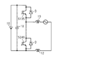
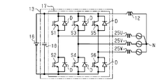
- the circuit diagram of the rotary electric machine apparatus of 1st Embodiment. An equivalent circuit of a rotating electrical machine apparatus in a state where electric power is supplied without applying torque to the motor.
- the circuit diagram of the rotary electric machine apparatus of 2nd Embodiment. (A) is a graph which shows the strength of the magnetic field by the electric current which flows into each motor winding, (b) is a schematic diagram which shows the relationship between the electric current and magnetic flux which flow through each motor winding. (A) is a graph which shows the intensity
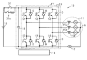
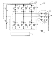
- FIG. 6 is a partially omitted circuit diagram of a rotating electrical machine apparatus according to another embodiment. Moreover, the partial abbreviation circuit diagram of the rotary electric machine apparatus of another embodiment. The circuit diagram of the rotary electric machine apparatus of another embodiment. The schematic block diagram of a prior art.
- the rotating electrical machine apparatus 10 includes a motor (rotating electrical machine) 11, a field winding 12, an inverter 13, and a control unit 14 configured to control the inverter 13.
- a motor rotating electrical machine
- the motor 11 a three-phase AC motor having three-phase motor windings 15U, 15V, and 15W is used.
- the inverter 13 is connected to a battery 16 as a DC power source, converts DC power (DC current) supplied from the battery 16 into three-phase AC power (three-phase AC current), and supplies it to the motor 11.
- the inverter 13 includes an inverter circuit 17 including six switching elements S1 to S6, and a capacitor 18 connected in parallel to the inverter circuit 17 on the input side of the inverter circuit 17.
- the inverter 13 is configured to be connectable to the battery 16.
- the inverter circuit 17 includes two switching elements S1, S2, S3, S4, S5, and S6 connected in series as a set, and the number of switching elements S1 corresponding to the number of phases of the motor windings 15U, 15V, and 15W. , S2, S3, S4, S5, S6. That is, the number of sets of the switching elements S1, S2, S3, S4, S5, and S6 corresponds to the number of phases of the motor windings 15U, 15V, and 15W. Specifically, the inverter circuit 17 includes three sets of switching elements S1, S2, S3, S4, S5, and S6.
- the three switching elements S1, S3, and S5 of the six switching elements S1 to S6 constitute an upper phase (upper arm), and the three switching elements S2, S4, S6 constitutes the lower phase (lower arm).
- a diode D is connected between the collector and emitter of each of the switching elements S1 to S6.
- the anode of each diode D is connected to the emitters of the corresponding switching elements S1 to S6.
- the cathode of each diode D is connected to the collectors of the corresponding switching elements S1 to S6.
- the motor windings 15U, 15V, 15W are connected by a star connection.
- Field winding 12 has a first end connected to neutral point N of the star connection.
- Field winding 12 has a second end connected to lower phase switching elements S2, S4, S6 of inverter 13.
- the field winding 12 is provided on a rotor (not shown) of the motor 11.
- a current is supplied to the field winding 12 through, for example, a brush and a slip ring.
- the control unit 14 is configured so that all the switching elements S1, S3, S5 in the upper phase of the inverter 13 perform the same operation, and all the switching elements S2, S4, S6 in the lower phase of the inverter 13 perform the same operation.
- the inverter 13 is controlled to supply a direct current to the magnetic winding 12.
- the control unit 14 includes a drive circuit (not shown), and the drive circuit is connected to the gates of the switching elements S1 to S6 via wiring (not shown).
- the control unit 14 can be realized by, for example, one or more dedicated hardware circuits and / or one or more processors (control circuits) that operate according to a computer program (software). That is, the control unit 14 can be realized by an electronic control device having an electric circuit programmed to execute a desired process.
- the processor includes a CPU and memories such as a RAM and a ROM.
- the memory stores program code or instructions configured to cause the processor to perform processing.
- Memory or computer readable media includes any available media that can be accessed by a general purpose or special purpose computer.
- the control unit 14 controls the inverter 13 so that all the switching elements S1, S3, S5 in the upper phase perform the same operation and all the switching elements S2, S4, S6 in the lower phase perform the same operation.
- the inverter 13 is controlled so that electric power is supplied from the battery 16 to the motor 11 via the inverter 13 in order to power the motor 11.
- the rotating electrical machine apparatus 10 is a circuit that performs the same operation as the circuit shown in FIG. However, illustration of the control unit 14 is omitted in FIG.
- one of the upper-phase switching elements S1, S3, and S5 and the lower-phase switching elements S2, S4, and S6 is on during one cycle of sequentially supplying current to the motor windings 15U, 15V, and 15W.
- the power (current) supplied to the field winding 12 can be adjusted by adjusting the duty while the other is off or vice versa. That is, a necessary current can be passed through the field winding 12 without providing a dedicated circuit.
- the rotating electrical machine apparatus 10 includes a field winding 12, star-connected three-phase motor windings 15U, 15V, and 15W, a plurality of switching elements S1 to S6, and a battery (DC power supply).
- 16 includes an inverter 13 that converts electric power from 16 to supply power to the motor windings 15U, 15V, and 15W, and a control unit 14 that is configured to control the inverter 13.
- Field winding 12 has a first end connected to neutral point N of the star connection and a second end connected to inverter 13.
- the inverter 13 includes two switching elements S1, S2, S3, S4, S5, and S6 connected in series as a set, and the number of switching elements S1 and S1 corresponding to the number of phases of the motor windings 15U, 15V, and 15W. S2, S3, S4, S5 and S6 are provided. Then, the control unit 14 performs the same operation for all the switching elements S1, S3, S5 in the upper phase of the inverter 13 and performs the same operation for all the switching elements S2, S4, S6 in the lower phase of the inverter 13.
- the inverter 13 is controlled to supply a direct current to the field winding 12 using a plurality of switching elements.
- the rotating electrical machine apparatus according to the second embodiment is greatly different from the first embodiment in that the inverter, the motor winding, and the field winding are doubled.
- the rotating electrical machine apparatus 20 includes a first rotating electrical machine unit M ⁇ b> 1 configured by a combination of a field winding 12, motor windings 15 ⁇ / b> U, 15 ⁇ / b> V, 15 ⁇ / b> W, and an inverter 13.
- the rotating electrical machine apparatus 20 further includes a second rotating electrical machine portion M2 configured by a combination of a field winding 22, motor windings 25U, 25V, and 25W and an inverter 23.
- the first rotating electrical machine part M1 and the second rotating electrical machine part M2 are connected in parallel to the battery 16, respectively.
- the first rotating electrical machine part M1 has basically the same configuration as the motor 11 of the first embodiment, and the same parts are denoted by the same reference numerals and detailed description thereof is omitted.
- the inverter 23 of the second rotating electrical machine part M2 includes an inverter circuit 27 composed of six switching elements S1 to S6 and a capacitor connected in parallel to the inverter circuit 27 on the input side of the inverter circuit 27. 18.
- the capacitor 18 is shared with the inverter 13 of the first rotating electrical machine part M1.
- the field winding 12 of the first rotating electrical machine part M1 has a first end connected to the neutral point N of the star connection, and a second end connected to the lower phase (lower arm) of the inverter 13. have.
- the field winding 22 of the second rotating electrical machine part M2 includes a first end connected to the neutral point N of the star connection, and a second end connected to the upper phase (upper arm) of the inverter 23. have. That is, of the field winding 12 and the field winding 22, the first end of one of the field windings 22 is connected to the neutral point N of the star connection, and the second end is the top of the inverter 23.
- the other end of the field winding 12 is connected to the neutral point N of the star connection and the second end is connected to the lower phase of the inverter 13.
- the U-phase motor windings 15U and 25U, the V-phase motor windings 15V and 25V, and the W-phase motor windings 15W and 25W of the first rotating electrical machine part M1 and the second rotating electrical machine part M2 are the same as the motor 21, respectively.
- the teeth (not shown) are wound double (in parallel).
- the winding direction of the motor windings 15U, 15V, 15W of the first rotating electrical machine part M1 is the same as the winding direction of the motor windings 25U, 25V, 25W of the second rotating electrical machine part M2. It is.
- the winding direction of the field winding 12 of the first rotating electrical machine part M1 is opposite to the winding direction of the field winding 22 of the second rotating electrical machine part M2.
- the control unit 30 is configured to control the first rotating electrical machine unit M1 and the second rotating electrical machine unit M2.
- all the switching elements S1, S3, S5 in the upper phase of the inverters 13, 23 and all the switching elements S2, S4, S6 in the lower phase of the inverters 13, 23 perform the same operation in synchronization.
- the inverters 13 and 23 are controlled.
- the control unit 30 controls the inverters 13 and 23 so as to perform the same operation in synchronization.
- All the switching elements S1, S3, S5 in the upper phase of the inverter 13 in the first rotating electrical machine part M1 and the inverter 23 in the second rotating electrical machine part M2 are off, and all the switching elements S2, in the lower phase of the inverters 13, 23 are turned off.
- S4 and S6 are on, no current flows from the inverters 13 and 23 to the motor windings 15U, 15V, 15W, 25U, 25V, and 25W.
- the duty is adjusted.
- the power (current) supplied to the field windings 12 and 22 can be adjusted. That is, a necessary current can be passed through the field windings 12 and 22 without providing a dedicated circuit.
- the winding direction of the motor windings 15U, 15V, 15W of the first rotating electrical machine part M1 is the same as the winding direction of the motor windings 25U, 25V, 25W of the second rotating electrical machine part M2. It is. Therefore, when current is supplied to the motor windings 15U, 15V, 15W, 25U, 25V, and 25W in order to drive the motor 21, the motor windings 15U, 15V, 15W, 25U, 25V, and 25W are supplied to the motor windings 15U, 15V, 15W, 25U, 25V, and 25W.
- the magnetic field generated by the flowing current is twice the magnetic field generated by only one of the motor windings 15U, 15V, 15W or the motor windings 25U, 25V, 25W. That is, as shown by the thick solid line in FIG. 4A, the magnetic field generated by the motor current is 2 of the magnetic field generated by only one of the motor windings 15U, 15V, 15W or the motor windings 25U, 25V, 25W indicated by the thin lines. Double.
- the horizontal axis indicates time.
- the solid arrow indicates the direction of current.
- the winding direction of the field winding 12 of the first rotating electrical machine part M1 is opposite to the winding direction of the field winding 22 of the second rotating electrical machine part M2. Since the current is supplied to the field winding 12 and the field winding 22 in opposite directions, when the current is supplied to the field winding 12 and the field winding 22, FIG. ), The magnetic field is doubled.
- the solid arrow indicates the direction of current.
- the second end of the field winding 12 is the lower phase of the inverter 13.
- the second end of the field winding 22 is connected to the upper phase (upper arm) of the inverter 23 in this embodiment. Therefore, when all the switching elements S1, S3, S5 in the upper phase of both inverters 13, 23 and all the switching elements S1, S3, S5 in the lower phase are operated synchronously, the field winding 12 Performs a step-down action, and the field winding 22 performs a step-up action.
- the rotating electrical machine apparatus 20 includes a first rotating electrical machine part M1 and a second rotating electrical machine part M2 connected in parallel.
- the first rotating electrical machine part M ⁇ b> 1 is configured by a combination of a field winding 12, motor windings 15 ⁇ / b> U, 15 ⁇ / b> V, 15 ⁇ / b> W, and an inverter 13.
- the second rotating electrical machine part M ⁇ b> 2 is configured by a combination of a field winding 22, motor windings 25 ⁇ / b> U, 25 ⁇ / b> V, 25 ⁇ / b> W, and an inverter 23.
- the winding direction of the motor windings 15U, 15V, 15W of the first rotating electrical machine part M1 is the same as the winding direction of the motor windings 25U, 25V, 25W of the second rotating electrical machine part M2.
- the winding direction of the field winding 12 of the first rotating electrical machine part M1 is opposite to the winding direction of the field winding 22 of the second rotating electrical machine part M2.
- the control unit 30 is configured to control the first rotating electrical machine unit M1 and the second rotating electrical machine unit M2.
- all the switching elements S1, S3, S5 in the upper phase of the inverters 13, 23 perform the same operation
- all the switching elements S2, S4, S6 in the lower phase of the inverters 13, 23 perform the same operation.
- the inverters 13 and 23 are controlled so as to supply a direct current to the field windings 12 and 22 using a plurality of switching elements.
- the target power can be supplied to the two field windings 12 and 22.
- the field winding 12 of the first rotating electrical machine part M1 has a first end connected to the neutral point N of the star connection and a second end connected to the upper phase (upper arm) of the inverter 13.
- the field winding 22 of the second rotating electrical machine part M2 has a first end connected to the neutral point N of the star connection and a second end connected to the lower phase (lower arm) of the inverter 23. . According to this configuration, noise is less likely to occur compared to a configuration in which the second end portions of both field windings 12 and 22 are connected to the same phase (upper phase or lower phase) of inverters 13 and 23.
- This embodiment calculates a command value Iq for the q-axis current and a command value Id for the d-axis current, and discharges the capacitor 18 by consuming electric charges in the motor windings.
- a different method is adopted.
- the purpose of the present embodiment is to enable discharging of a capacitor without generating torque in the motor 11 even when rotation angle sensorless control is performed.
- the rotating electrical machine apparatus 10 includes a capacitor (smoothing capacitor) 18 connected in parallel to a battery 16 serving as a DC power source and an inverter 13.
- the rotating electrical machine apparatus 10 includes a relay connected between the battery 16 and the capacitor 18 and configured to connect or disconnect the battery 16 and the capacitor (smoothing capacitor) 18 according to the first embodiment. Is different.
- the relay includes a relay 31 and a precharge relay 31a connected in parallel. That is, the rotating electrical machine apparatus 10 of the present embodiment is different from the first embodiment in that a relay 31 and a precharge relay 31a are provided between the battery 16 and the capacitor 18.
- Each of the relay 31 and the precharge relay 31a is turned on / off by a command from the control unit 14.
- the control unit 14 turns off all the switching elements S1 and S3 in the upper phase of the inverter 13 so that the electric charge of the capacitor (smoothing capacitor) 18 is consumed by the field winding 12 with the relay 31 and the precharge relay 31a turned off.
- S5 are turned on, and all the switching elements S2, S4, S6 in the lower phase of the inverter 13 are turned off.
- the rotation angle of the motor 11 is not known, and therefore torque may be generated in the motor 11.
- the rotating electrical machine device 10 is mounted on a vehicle, if torque is generated in the motor 11 and the motor 11 rotates, there is a possibility that a person on the vehicle may feel uncomfortable.
- the rotating electrical machine apparatus 10 includes a motor 11 having a plurality of phases of motor windings 15U, 15V, and 15W as a stator, and an inverter 13 that can supply power to the motor 11.
- the inverter 13 is a combination of switching elements composed of upper-phase switching elements S1, S3, S5 and lower-phase switching elements S2, S4, S6 connected in series with each other. , Every 15W.
- the rotating electrical machine apparatus 10 includes a battery 16 serving as a DC power source and a capacitor (smoothing capacitor) 18 connected in parallel between the inverter 13.
- the control unit 14 turns on at least one of the switching elements in the lower phase of the inverter 13 and activates the corresponding inverter 13 when starting the inverter 13 before the predetermined time has elapsed after the operation of the inverter 13 is stopped.
- the phase switching element is turned off. “Before the predetermined time has elapsed” means within a time (for example, several tens of milliseconds) that the field winding 12 has sufficiently accumulated energy after the operation of the inverter 13 is stopped. If so, the energy reuse control is performed according to the flowchart of FIG.
- step S12 the control unit 14 determines whether or not the operation signal (INV operation signal) of the inverter 13 has been received. If it is determined that the INV operation signal has been received, the control unit 14 proceeds to step S13. The controller 14 determines whether or not a stop signal (INV stop signal) for the inverter 13 has been received in step S13. If the control unit 14 determines that the signal has been received, the process proceeds to step S14 where the stop flag is set to 1 and the stop timer adds (+) the count value.
- step S15 determines whether or not the start signal (INV start signal) of the inverter 13 has been received in step S15.
- the control unit 14 proceeds to step S16.
- step S15.1 the stop timer adds (+) the count value, and returns to step S15.
- step S16 the control unit 14 determines whether or not the count value of the stop timer is equal to or less than the upper limit value (for example, several tens of milliseconds) for performing the reuse control and the stop flag is 1. If the count value of the stop timer is less than or equal to the upper limit value and the stop flag is 1 in step S16, the control unit 14 proceeds to step S17. In step S17, the control unit 14 performs reuse control, sets the pause flag to 0, and sets the pause timer to 0. Thereafter, the control unit 14 proceeds to step S18 and determines whether or not an operation end signal has been received.
- the upper limit value for example, several tens of milliseconds
- step S18 If the operation end signal is not received in step S18, the control unit 14 returns to step S13 and repeats the operations after step S13.
- the control part 14 will complete
- step S16 If the count value of the stop timer is not less than or equal to the upper limit value in step S16, the control unit 14 proceeds to step S19, sets the pause flag to 0, sets the pause timer to 0, and then proceeds to step S18.
- the upper-phase switching elements S1, S3, and S5 of the inverter 13 are all turned off, and at least one of the lower-phase switching elements S2, S4, and S6 is turned on.
- the energy accumulated in the field winding 12 is applied to the switching elements S2, S4, and S6 as shown by arrows in FIG. Then, it flows to the motor windings 15U, 15V, 15W, and energy is reused.
- FIG. 9 shows a state in which the upper phase switching elements S1, S3, and S5 are all turned off and the lower phase switching elements S2, S4, and S6 are all turned on.
- S5 may be turned off, and one or two of the lower phase switching elements S2, S4, S6 may be controlled to be turned on.
- it is mainly to control one or two of the lower-phase switching elements S2, S4, S6 to be on.
- the present invention is not limited to the above embodiment, and may be embodied as follows, for example.
- the second end of the field winding 12 may be connected to the upper phase of the inverter 13 in the first embodiment.
- illustration of the control part 14 is abbreviate
- the second end of the field winding 12 of the first rotating electrical machine part M1 is connected to the upper phase (upper arm) of the inverter 13, and the field winding of the second rotating electrical machine part M2
- the second end portion of 22 may be connected to the lower phase (lower arm) of the inverter 23.
- one of the field winding 12 and the field winding 22 performs a step-up action, and the other performs a step-down action. Therefore, compared to a configuration in which the second ends of both field windings 12 and 22 are connected to the same phase (upper phase or lower phase) of inverters 13 and 23, noise is less likely to occur.
- the first end of the field winding 22 of the second rotating electrical machine part M2 is connected to the neutral point N of the star connection, and the field winding 22 May be connected to the lower phase (lower arm) of the inverter 23. That is, the second ends of the field winding 12 and the field winding 22 may be connected to the lower phase (lower arm) of the inverters 13 and 23. However, illustration of the control unit 30 is omitted in FIG. Also, contrary to FIG. 12, the second ends of the field winding 12 and the field winding 22 may be connected to the upper phase (upper arm) of the inverters 13 and 23. However, in any case, the winding direction of the field winding 12 and the field winding 22 is reversed.
- the capacitor 18 constituting the inverter 13 may be connected not in parallel to the inverter circuit 17 but in series and in series with the battery 16. Further, the second end of the field winding 12 having the first end connected to the neutral point N may be connected between the battery 16 and the capacitor 18.
- motor windings 15U, 25U, 15V, 25V, 15W, 25W may be wound around teeth that are shifted by 30 degrees.
- the field windings 12 and 22 are not limited to the configuration provided in the rotor (not shown) of the motor 11, and field windings may be provided in the stator. In addition to the field winding, a permanent magnet may be provided on the stator.
- the star winding motor winding is not limited to three phases, but may be three or more phases, for example, four phases or five phases.
- the rotating electrical machine device has two rotating electrical machine units connected in parallel.
- the rotating electrical machine apparatus may include an even number of four or more rotating electrical machines connected in parallel.
Landscapes
- Engineering & Computer Science (AREA)
- Power Engineering (AREA)
- Control Of Ac Motors In General (AREA)
Abstract
回転電機装置は、界磁巻線と、星形結線された3相のモータ巻線と、複数のスイッチング素子を有するとともに、バッテリからの電力を電力変換してモータ巻線に供給するインバータと、インバータを制御するように構成された制御部とを備える。制御部は、インバータの上相の全てのスイッチング素子が同じ動作をし、下相の全てのスイッチング素子が同じ動作をする間に、複数のスイッチング素子を用いて界磁巻線に直流電流を供給するようにインバータを制御する。
Description
本発明は、回転電機装置に係り、詳しくは回転電機と回転電機を制御するインバータを備えた回転電機装置に関する。
従来、電機子巻線形モータ(界磁巻線形モータ)にはDC電流を流す必要がある。その際にはDC電流を流す専用回路(スイッチ等)が必要である。
例えば、特許文献1に開示された電動機駆動装置では、図14に示すように、電動機81のU相コイルU、V相コイルV、W相コイルWにインバータ82を介して電流が供給される。また、電動機81の界磁巻線(コイル)83は、バッテリBおよび電源ライン84間の電流経路上に電気的に接続され、昇圧コンバータ85のリアクトルL1として機能する。昇圧コンバータ85は、リアクトルL1と、スイッチング素子Q1及びスイッチング素子Q2とを含む。
例えば、特許文献1に開示された電動機駆動装置では、図14に示すように、電動機81のU相コイルU、V相コイルV、W相コイルWにインバータ82を介して電流が供給される。また、電動機81の界磁巻線(コイル)83は、バッテリBおよび電源ライン84間の電流経路上に電気的に接続され、昇圧コンバータ85のリアクトルL1として機能する。昇圧コンバータ85は、リアクトルL1と、スイッチング素子Q1及びスイッチング素子Q2とを含む。
制御装置86は、電圧指令値と電圧センサ87からの検出電圧との偏差に基づいて電源ライン84への入力電流の目標値を算出し、かつ、電流指令値と電流センサ88からの検出電流との偏差に応じて界磁巻線83に流れる界磁増磁電流の目標値を算出する。制御装置86は、入力電流および界磁電流の目標値の合計値に、フィードフォワード補償項としてのモータ出力電流を加算して電流指令値を生成すると、電流センサ88からの検出電流が電流指令値に一致するようにスイッチング素子Q1、Q2,Q3をスイッチング制御する。
界磁巻線はモータ磁界を操作してモータの小型化と高出力化に寄与する。しかし、特許文献1の構成では、界磁巻線に流れる電流を制御する専用回路が必要になり、その分、製造コストが増大する。
本発明の目的は、専用回路を設けることなく界磁巻線に必要な電流を流すことができる回転電機装置を提供することにある。
上記目的を達成する回転電機装置は、界磁巻線と、星形結線された3相以上の多相のモータ巻線と、複数のスイッチング素子を有するとともに、直流電源からの電力を変換して前記モータ巻線に供給するインバータと、前記インバータを制御するように構成された制御部とを備える。前記界磁巻線は、前記星形結線の中性点に接続された第1端部と、前記インバータに接続された第2端部とを有する。前記インバータは、直列接続された2個のスイッチング素子を一組とする複数組のスイッチング素子を有し、前記スイッチング素子の組の数は前記モータ巻線の相数に対応している。前記制御部は、前記インバータの上相の全ての前記スイッチング素子が同じ動作をし、前記インバータの下相の全ての前記スイッチング素子が同じ動作をする間に、前記複数のスイッチング素子を用いて前記界磁巻線に直流電流を供給するように前記インバータを制御するように構成されている。
(第1の実施形態)
以下、本発明を具体化した回転電機装置の第1の実施形態を図1及び図2にしたがって説明する。
以下、本発明を具体化した回転電機装置の第1の実施形態を図1及び図2にしたがって説明する。
図1に示すように、回転電機装置10は、モータ(回転電機)11と、界磁巻線12と、インバータ13と、インバータ13を制御するように構成された制御部14とを有する。モータ11には、3相のモータ巻線15U,15V,15Wを有する3相交流モータが用いられている。
インバータ13は、直流電源としてのバッテリ16に接続され、バッテリ16から供給される直流電力(直流電流)を3相交流電力(3相交流電流)に変換してモータ11に供給する。インバータ13は、6個のスイッチング素子S1~S6よりなるインバータ回路17と、インバータ回路17の入力側においてインバータ回路17に並列に接続されたコンデンサ18とを備えている。インバータ13は、バッテリ16に接続可能に構成されている。
各スイッチング素子S1~S6として、例えば、IGBT(絶縁ゲートバイポーラトランジスタ)が使用されている。インバータ回路17は、直列接続された2個のスイッチング素子S1,S2、S3,S4、S5,S6を一組として、モータ巻線15U,15V,15Wの相数に対応した組数のスイッチング素子S1,S2、S3,S4、S5,S6を備えている。即ち、スイッチング素子S1,S2、S3,S4、S5,S6の組数は、モータ巻線15U,15V,15Wの相数に対応している。具体的には、インバータ回路17は、3組のスイッチング素子S1,S2、S3,S4、S5,S6を備えている。
詳述すると、インバータ回路17は、6個のスイッチング素子S1~S6のうち、3個のスイッチング素子S1,S3,S5が上相(上アーム)を構成し、3個のスイッチング素子S2,S4,S6が下相(下アーム)を構成する。各スイッチング素子S1~S6のコレクタとエミッタ間には、ダイオードDがそれぞれ接続されている。各ダイオードDのアノードが、対応するスイッチング素子S1~S6のエミッタに接続されている。各ダイオードDのカソードが、対応するスイッチング素子S1~S6のコレクタに接続されている。
モータ巻線15U,15V,15Wは星形結線で接続されている。界磁巻線12は、星形結線の中性点Nに接続された第1端部を有する。界磁巻線12は、インバータ13の下相のスイッチング素子S2,S4,S6に接続された第2端部を有する。界磁巻線12は、モータ11のロータ(図示せず)に設けられている。界磁巻線12には、例えばブラシ及びスリップリングを介して電流が供給されるようになっている。
制御部14は、インバータ13の上相の全てのスイッチング素子S1,S3,S5が同じ動作をし、インバータ13の下相の全てのスイッチング素子S2,S4,S6が同じ動作をする間に、界磁巻線12に直流電流を供給するようにインバータ13を制御するように構成されている。制御部14は、図示しない駆動回路を備え、駆動回路は配線(図示せず)を介して各スイッチング素子S1~S6のゲートに接続されている。
制御部14は、例えば、1つ以上の専用のハードウェア回路、及び/又は、コンピュータプログラム(ソフトウェア)に従って動作する1つ以上のプロセッサ(制御回路)によって実現することができる。即ち、制御部14は、所望の処理を実行するようにプログラムされた電気回路(circuitry)を有する電子制御装置によって実現することができる。プロセッサは、CPU並びに、RAM及びROM等のメモリを有する。メモリは、処理をプロセッサに実行させるように構成されたプログラムコードまたは指令を格納している。メモリすなわちコンピュータ可読媒体は、汎用または専用のコンピュータでアクセスできるあらゆる利用可能な媒体を含む。
制御部14は、上相の全てのスイッチング素子S1,S3,S5が同じ動作をし、下相の全てのスイッチング素子S2,S4,S6が同じ動作をするようにインバータ13を制御するとき以外のときに、モータ11を力行させるため、バッテリ16からインバータ13を介してモータ11に電力を供給するようにインバータ13を制御するように構成されている。
次に前記のように構成された回転電機装置10の作用を説明する。
インバータ13の上相の全てのスイッチング素子S1,S3,S5がオフで、インバータ13の下相の全てのスイッチング素子S2,S4,S6がオンの状態では、インバータ13からモータ巻線15U,15V,15Wには電流が流れない。
インバータ13の上相の全てのスイッチング素子S1,S3,S5がオフで、インバータ13の下相の全てのスイッチング素子S2,S4,S6がオンの状態では、インバータ13からモータ巻線15U,15V,15Wには電流が流れない。
インバータ13の上相の全てのスイッチング素子S1,S3,S5がオンで、下相の全てのスイッチング素子S2,S4,S6がオフの状態では、インバータ13を介してモータ巻線15U,15V,15Wに電流が流れるが、全てのモータ巻線15U,15V,15Wに同じ状態で電流が流れるため、モータ(回転電機)11にはトルクが生じない。この状態では、回転電機装置10は、図2に示す回路と同じ動作を行う回路となる。但し、図2では制御部14の図示を省略している。
図2に示す回路において、スイッチング素子S246がオフの状態で、スイッチング素子S135をオンにすると、バッテリ16の電圧がコイル19及び界磁巻線12に印加される。その状態から、スイッチング素子S135をオフにすると、スイッチング素子S246と接続されているダイオードを介して電流がコイル19及び界磁巻線12を流れる。そのため、回転電機装置10は、降圧コンバータとして動作する。これに対して、図2に示す回路において、スイッチング素子S135がオンの状態で、スイッチング素子S246のスイッチングを行うと、回転電機装置10は、昇圧コンバータとして動作する。
したがって、モータ巻線15U,15V,15Wに順次電流を供給する1周期の間のうち、上相のスイッチング素子S1,S3,S5と下相のスイッチング素子S2,S4,S6との一方がオンで他方がオフあるいはその逆の状態で、そのデューティを調整することにより、界磁巻線12に供給される電力(電流)を調整することができる。すなわち、専用回路を設けることなく界磁巻線12に必要な電流を流すことができる。
この実施形態によれば、以下に示す効果を得ることができる。
(1)回転電機装置10は、界磁巻線12と、星形結線された3相のモータ巻線15U,15V,15Wと、複数のスイッチング素子S1~S6を有するとともに、バッテリ(直流電源)16からの電力を電力変換してモータ巻線15U,15V,15Wに電力供給するインバータ13と、インバータ13を制御するように構成された制御部14とを有する。界磁巻線12は、星形結線の中性点Nに接続された第1端部と、インバータ13に接続された第2端部とを有する。インバータ13は、直列接続された2個のスイッチング素子S1,S2、S3,S4、S5,S6を一組として、モータ巻線15U,15V,15Wの相数に対応した組数のスイッチング素子S1,S2、S3,S4、S5,S6を備えている。そして、制御部14は、インバータ13の上相の全てのスイッチング素子S1,S3,S5が同じ動作をし、インバータ13の下相の全てのスイッチング素子S2,S4,S6が同じ動作をする間に、複数のスイッチング素子を用いて界磁巻線12に直流電流を供給するようにインバータ13を制御するように構成されている。
(1)回転電機装置10は、界磁巻線12と、星形結線された3相のモータ巻線15U,15V,15Wと、複数のスイッチング素子S1~S6を有するとともに、バッテリ(直流電源)16からの電力を電力変換してモータ巻線15U,15V,15Wに電力供給するインバータ13と、インバータ13を制御するように構成された制御部14とを有する。界磁巻線12は、星形結線の中性点Nに接続された第1端部と、インバータ13に接続された第2端部とを有する。インバータ13は、直列接続された2個のスイッチング素子S1,S2、S3,S4、S5,S6を一組として、モータ巻線15U,15V,15Wの相数に対応した組数のスイッチング素子S1,S2、S3,S4、S5,S6を備えている。そして、制御部14は、インバータ13の上相の全てのスイッチング素子S1,S3,S5が同じ動作をし、インバータ13の下相の全てのスイッチング素子S2,S4,S6が同じ動作をする間に、複数のスイッチング素子を用いて界磁巻線12に直流電流を供給するようにインバータ13を制御するように構成されている。
この構成によれば、インバータ13の上相の全てのスイッチング素子S1,S3,S5がオフで、下相の全てのスイッチング素子S2,S4,S6がオンの状態あるいは、インバータ13の上相の全てのスイッチング素子がオンで、下相の全てのスイッチング素子がオフの状態で、そのデューティを制御することにより昇圧コンバータあるいは降圧コンバータとして動作する。したがって、専用回路を設けることなく界磁巻線12に必要な電流を流すことができる。
(第2の実施形態)
次に、第2の実施形態を図3~図5にしたがって説明する。
第2の実施形態の回転電機装置は、インバータ、モータ巻線、及び界磁巻線を二重にした点が第1の実施形態と大きく異なっている。
次に、第2の実施形態を図3~図5にしたがって説明する。
第2の実施形態の回転電機装置は、インバータ、モータ巻線、及び界磁巻線を二重にした点が第1の実施形態と大きく異なっている。
図3に示すように、回転電機装置20は、界磁巻線12と、モータ巻線15U,15V,15Wと、インバータ13との組みによって構成される第1回転電機部M1を備える。回転電機装置20は、界磁巻線22と、モータ巻線25U,25V,25Wと、インバータ23との組みによって構成される第2回転電機部M2を更に備える。第1回転電機部M1及び第2回転電機部M2が、それぞれバッテリ16に並列に接続されている。第1回転電機部M1は、第1の実施形態のモータ11と基本的に同じ構成であり、同様な部分は同一符号を付して詳細な説明を省略する。
図3に示すように、第2回転電機部M2のインバータ23は、6個のスイッチング素子S1~S6よりなるインバータ回路27と、インバータ回路27の入力側においてインバータ回路27に並列に接続されたコンデンサ18とを備えている。コンデンサ18は第1回転電機部M1のインバータ13と共用されている。
第1回転電機部M1の界磁巻線12は、星形結線の中性点Nに接続された第1端部と、インバータ13の下相(下アーム)に接続された第2端部とを有している。第2回転電機部M2の界磁巻線22は、星形結線の中性点Nに接続された第1端部と、インバータ23の上相(上アーム)に接続された第2端部とを有している。即ち、界磁巻線12及び界磁巻線22のうち、一方の界磁巻線22の第1端部が星形結線の中性点Nに接続され、第2端部がインバータ23の上相に接続され、他方の界磁巻線12は、第1端部が星形結線の中性点Nに接続され、第2端部がインバータ13の下相に接続されている。
第1回転電機部M1及び第2回転電機部M2のU相のモータ巻線15U,25U、V相のモータ巻線15V,25V、W相のモータ巻線15W,25Wは、それぞれモータ21の同じティース(図示せず)に二重(並列)に巻かれている。
図4(b)に示すように、第1回転電機部M1のモータ巻線15U,15V,15Wの巻き方向は、第2回転電機部M2のモータ巻線25U,25V,25Wの巻き方向と同じである。
図5(b)に示すように、第1回転電機部M1の界磁巻線12の巻き方向は、第2回転電機部M2の界磁巻線22の巻き方向と逆である。
制御部30は、第1回転電機部M1及び第2回転電機部M2を制御するように構成されている。制御部30は、インバータ13,23の上相の全てのスイッチング素子S1,S3,S5と、インバータ13,23の下相の全てのスイッチング素子S2,S4,S6とが同期して同じ動作をするようにインバータ13,23を制御する。回転電機装置20、即ち制御部30は、インバータ13,23の上相の全てのスイッチング素子S1,S3,S5が同じ動作をし、インバータ13,23の下相の全てのスイッチング素子S2,S4,S6が同じ動作をする間に、複数のスイッチング素子S1,S3,S5及びスイッチング素子S2,S4,S6を用いて界磁巻線12,22に直流電流を供給するようにインバータ13,23を制御する。
制御部30は、第1回転電機部M1及び第2回転電機部M2を制御するように構成されている。制御部30は、インバータ13,23の上相の全てのスイッチング素子S1,S3,S5と、インバータ13,23の下相の全てのスイッチング素子S2,S4,S6とが同期して同じ動作をするようにインバータ13,23を制御する。回転電機装置20、即ち制御部30は、インバータ13,23の上相の全てのスイッチング素子S1,S3,S5が同じ動作をし、インバータ13,23の下相の全てのスイッチング素子S2,S4,S6が同じ動作をする間に、複数のスイッチング素子S1,S3,S5及びスイッチング素子S2,S4,S6を用いて界磁巻線12,22に直流電流を供給するようにインバータ13,23を制御する。
次に前記のように構成された回転電機装置20の作用を説明する。
第1回転電機部M1の上アームと第2回転電機部M2の上アームとが同期して同じ動作を行い、第1回転電機部M1の下アームと第2回転電機部M2の下アームとが同期して同じ動作を行うように、制御部30がインバータ13,23を制御する。
第1回転電機部M1の上アームと第2回転電機部M2の上アームとが同期して同じ動作を行い、第1回転電機部M1の下アームと第2回転電機部M2の下アームとが同期して同じ動作を行うように、制御部30がインバータ13,23を制御する。
第1回転電機部M1のインバータ13及び第2回転電機部M2のインバータ23の上相の全てのスイッチング素子S1,S3,S5がオフで、インバータ13,23の下相の全てのスイッチング素子S2,S4,S6がオンの状態では、インバータ13,23からモータ巻線15U,15V,15W,25U,25V,25Wには電流が流れない。
インバータ13,23の上相の全てのスイッチング素子S1,S3,S5がオンで、下相の全てのスイッチング素子S2,S4,S6がオフの状態では、インバータ13,23を介してモータ巻線15U,15V,15W,25U,25V,25Wに電流が流れるが、全てのモータ巻線15U,15V,15W,25U,25V,25Wに同じ状態で電流が流れるため、モータ(回転電機)21にはトルクが生じない。
したがって、インバータ13,23の上相のスイッチング素子S1,S3,S5と下相のスイッチング素子S2,S4,S6の一方がオンで他方がオフあるいはその逆の状態のときに、そのデューティを調整することにより、界磁巻線12,22に供給される電力(電流)を調整することができる。すなわち、専用回路を設けることなく界磁巻線12,22に必要な電流を流すことができる。
図4(b)に示すように、第1回転電機部M1のモータ巻線15U,15V,15Wの巻き方向は、第2回転電機部M2のモータ巻線25U,25V,25Wの巻き方向と同じである。そのため、モータ21を駆動するためにモータ巻線15U,15V,15W,25U,25V,25Wに、同じ位相で電流が供給されると、モータ巻線15U,15V,15W,25U,25V,25Wに流れる電流により発生する磁界は、モータ巻線15U,15V,15Wあるいはモータ巻線25U,25V,25Wの一方だけによる磁界の2倍になる。即ち、図4(a)に太い実線で示すように、モータ電流により発生する磁界は、細線で示すモータ巻線15U,15V,15Wあるいはモータ巻線25U,25V,25Wの一方だけによる磁界の2倍になる。なお、図4(a)において横軸は時間を示す。また、図4(b)において実線の矢印は、電流の向きを示す。
図5(b)に示すように、第1回転電機部M1の界磁巻線12の巻き方向、第2回転電機部M2の界磁巻線22の巻き方向と逆である。そして、界磁巻線12及び界磁巻線22に対して電流が互いに逆方向に供給されるため、界磁巻線12及び界磁巻線22に電流が供給されると、図5(a)に示すように、磁界は2倍になる。なお、図5(b)において実線の矢印は、電流の向きを示す。
第1端部が星形結線の中性点Nにそれぞれ接続された界磁巻線12,22のうちの一方、この実施形態では界磁巻線12の第2端部はインバータ13の下相(下アーム)に接続され、他方、この実施形態では界磁巻線22の第2端部はインバータ23の上相(上アーム)に接続されている。そのため、両インバータ13,23の上相の全てのスイッチング素子S1,S3,S5と、下相の全てのスイッチング素子S1,S3,S5とが同期して同じ動作をした場合、界磁巻線12は降圧作用を行い、界磁巻線22は昇圧作用を行う。
この第2の実施形態によれば、第1の実施形態の効果(1)と同様の効果に加えて、以下の効果を得ることができる。
(2)回転電機装置20は、並列に接続された第1回転電機部M1及び第2回転電機部M2を備える。第1回転電機部M1は、界磁巻線12と、モータ巻線15U,15V,15Wと、インバータ13との組みによって構成されている。第2回転電機部M2は、界磁巻線22と、モータ巻線25U,25V,25Wと、インバータ23との組みによって構成されている。
(2)回転電機装置20は、並列に接続された第1回転電機部M1及び第2回転電機部M2を備える。第1回転電機部M1は、界磁巻線12と、モータ巻線15U,15V,15Wと、インバータ13との組みによって構成されている。第2回転電機部M2は、界磁巻線22と、モータ巻線25U,25V,25Wと、インバータ23との組みによって構成されている。
第1回転電機部M1のモータ巻線15U,15V,15Wの巻き方向は、第2回転電機部M2のモータ巻線25U,25V,25Wの巻き方向と同じである。第1回転電機部M1の界磁巻線12の巻き方向は、第2回転電機部M2の界磁巻線22の巻き方向と逆である。
制御部30は、第1回転電機部M1及び第2回転電機部M2を制御するように構成されている。制御部30は、インバータ13,23の上相の全てのスイッチング素子S1,S3,S5が同じ動作をし、インバータ13,23の下相の全てのスイッチング素子S2,S4,S6が同じ動作をする間に、複数のスイッチング素子を用いて界磁巻線12,22に直流電流を供給するようにインバータ13,23を制御するように構成されている。
したがって、モータ巻線15U,15V,15W,25U,25V,25W、界磁巻線12,22及びインバータ13,23を二重にした場合、界磁巻線用のスイッチを二重にしなくても2つの界磁巻線12,22に目的の電力(電流)を供給することができる。
(3)相電流が3相から6相になることにより、モータ21に同じ電流(電力)を供給した場合、インバータ13,23における発熱を分散でき、冷却を簡素化できる。
(4)第1回転電機部M1の界磁巻線12は、第1端部が星形結線の中性点Nに接続され、第2端部がインバータ13の上相(上アーム)に接続されている。第2回転電機部M2の界磁巻線22は、第1端部が星形結線の中性点Nに接続され、第2端部がインバータ23の下相(下アーム)に接続されている。この構成によれば、両界磁巻線12,22の第2端部がインバータ13,23の同じ相(上相あるいは下相)に接続された構成に比べて、ノイズが発生し難い。
(4)第1回転電機部M1の界磁巻線12は、第1端部が星形結線の中性点Nに接続され、第2端部がインバータ13の上相(上アーム)に接続されている。第2回転電機部M2の界磁巻線22は、第1端部が星形結線の中性点Nに接続され、第2端部がインバータ23の下相(下アーム)に接続されている。この構成によれば、両界磁巻線12,22の第2端部がインバータ13,23の同じ相(上相あるいは下相)に接続された構成に比べて、ノイズが発生し難い。
(第3の実施形態)
次に、第3の実施形態を図6にしたがって説明する。なお、モータ11及びインバータ13は、第1の実施形態と基本的に同じ構成であり、同様な部分は同一符号を付して詳細な説明を省略する。
次に、第3の実施形態を図6にしたがって説明する。なお、モータ11及びインバータ13は、第1の実施形態と基本的に同じ構成であり、同様な部分は同一符号を付して詳細な説明を省略する。
この実施形態は、q軸電流の指令値Iq及びd軸電流の指令値Idを計算して、モータ巻線で電荷消費を行うことにより、コンデンサ18の放電を行う従来から提案されている方式と異なる方式を採用している。本実施形態では、回転角センサレス制御が行われる場合であっても、モータ11にトルクを発生させることなくコンデンサの放電を可能にすることを目的としている。
具体的には、回転電機装置10は、図6に示すように、直流電源としてのバッテリ16とインバータ13とに対して並列接続されたコンデンサ(平滑コンデンサ)18を備える。回転電機装置10は、バッテリ16とコンデンサ18との間に接続され、バッテリ16とコンデンサ(平滑コンデンサ)18とを接続又は切断するように構成されたリレーを備えている点が第1の実施形態と異なっている。リレーは、並列に接続されたリレー31及びプリチャージリレー31aを有する。即ち、本実施形態の回転電機装置10は、バッテリ16とコンデンサ18との間に、リレー31及びプリチャージリレー31aを備えている点が第1の実施形態と異なっている。
リレー31及びプリチャージリレー31aの各々は、制御部14からの指令によりオン、オフされる。制御部14は、リレー31及びプリチャージリレー31aをオフした状態で、コンデンサ(平滑コンデンサ)18の電荷を界磁巻線12で消費させるようにインバータ13の上相の全てのスイッチング素子S1,S3,S5をオンしかつインバータ13の下相の全てのスイッチング素子S2,S4,S6をオフとする。
センサレス制御を仮定した場合、一般的な放電制御であるd軸に電流を流す方法では、モータ11の回転角がわからないため、モータ11にトルクが発生する可能性がある。回転電機装置10が車両に搭載された場合、モータ11にトルクが発生して回転すると、車両に乗っている人に不快感を与える虞がある。
しかし、この実施形態では、放電制御を行う場合、U相、V相及びW相の各モータ巻線15U,15V,15Wに同じ大きさの電流が流れる。その電流が合流して界磁巻線12を流れるため、モータ11にトルクは発生しない。したがって、回転角センサレス制御、かつ中性点Nに界磁巻線12が接続されている場合、モータ11にトルクが発生することなくコンデンサ18の放電を行うことができる。なお、放電制御は、例えば、モータ11の運転を終了(キーオフ)した場合に、全てのスイッチング素子S1~S6をオフとした後、上アームのスイッチング素子S1,S3,S5を全てオンすることにより、実施される。
(第4の実施形態)
次に、第4の実施形態を図7~図10にしたがって説明する。
この実施形態においては、インバータ13の動作停止後、界磁巻線12に溜まっているエネルギーを再利用することを可能にすることを目的としている。回転電機装置10の構成は第1の実施形態と同じであるが、インバータ13の動作停止後に、インバータ13が再始動した場合、界磁巻線12に溜まっているエネルギーを再利用するように下アームのスイッチング素子S2,S4,S6を制御する方法が異なっている。
次に、第4の実施形態を図7~図10にしたがって説明する。
この実施形態においては、インバータ13の動作停止後、界磁巻線12に溜まっているエネルギーを再利用することを可能にすることを目的としている。回転電機装置10の構成は第1の実施形態と同じであるが、インバータ13の動作停止後に、インバータ13が再始動した場合、界磁巻線12に溜まっているエネルギーを再利用するように下アームのスイッチング素子S2,S4,S6を制御する方法が異なっている。
図7に示すように、回転電機装置10は、複数相のモータ巻線15U,15V,15Wをステータに有するモータ11と、モータ11に電力を供給可能なインバータ13とを有する。インバータ13は、互いに直列に接続された上相のスイッチング素子S1,S3,S5と下相のスイッチング素子S2,S4,S6とから構成されるスイッチング素子の組みを3相のモータ巻線15U,15V,15W毎に有する。
回転電機装置10は、直流電源としてのバッテリ16と、インバータ13との間に並列接続されたコンデンサ(平滑コンデンサ)18とを有する。
制御部14は、インバータ13の動作停止後、所定時間経過する前にインバータ13を起動する場合に、インバータ13の下相のスイッチング素子のうちの少なくとも1つをオンするとともに対応するインバータ13の上相のスイッチング素子をオフする。所定時間経過する前とは、インバータ13の動作停止後、界磁巻線12にエネルギーが十分に溜まっている時間以内(例えば、数10ms)を意味し、所定時間経過前の起動(再始動)であれば、図8のフローチャートにしたがってエネルギー再利用制御を行う。
制御部14は、インバータ13の動作停止後、所定時間経過する前にインバータ13を起動する場合に、インバータ13の下相のスイッチング素子のうちの少なくとも1つをオンするとともに対応するインバータ13の上相のスイッチング素子をオフする。所定時間経過する前とは、インバータ13の動作停止後、界磁巻線12にエネルギーが十分に溜まっている時間以内(例えば、数10ms)を意味し、所定時間経過前の起動(再始動)であれば、図8のフローチャートにしたがってエネルギー再利用制御を行う。
制御が開始されると、制御部14は、ステップS11で停止フラグ=0、停止タイマ=0とする。制御部14は、次にステップS12でインバータ13の動作信号(INV動作信号)を受信したか否かの判断を行い、INV動作信号を受信したと判断するとステップS13に進む。制御部14は、ステップS13でインバータ13の停止信号(INV停止信号)を受信したか否かの判断を行う。制御部14は、受信したと判断するとステップS14に進み、停止フラグを1にするとともに停止タイマはカウント値を加算(+)する。制御部14は、次にステップS15に進み、ステップS15ではインバータ13の始動信号(INV始動信号)を受信したか否かの判断を行う。制御部14は、始動信号(INV始動信号)を受信したと判断した場合、ステップS16に進む。制御部14は、始動信号(INV始動信号)を受信していないと判断した場合、ステップS15.1に進み、停止タイマはカウント値を加算(+)し、ステップS15に戻る。
制御部14は、ステップS16では停止タイマのカウント値が、再利用制御を行う上限値(例えば、数10ms)以下で、かつ停止フラグが1であるか否かを判断する。制御部14は、ステップS16で停止タイマのカウント値が上限値以下で、かつ停止フラグが1であればステップS17に進む。制御部14は、ステップS17において再利用制御を行うとともに一時停止フラグを0、一時停止タイマを0にする。その後、制御部14は、ステップS18に進み、運転終了信号を受信したか否かを判断する。
制御部14は、ステップS18で運転終了信号を受信していなければステップS13に戻り、ステップS13以降の動作を繰り返す。制御部14は、運転終了信号を受信していれば運転を終了する。
制御部14は、ステップS16で停止タイマのカウント値が上限値以下でなければステップS19に進み、一時停止フラグを0、一時停止タイマを0にした後、ステップS18に進む。
ステップS17で再利用制御が行われると、インバータ13の上相のスイッチング素子S1,S3,S5が全てオフに、下相のスイッチング素子S2,S4,S6の少なくとも1つがオンに制御される。例えば、下相の全てのスイッチング素子S2,S4,S6がオンに制御されると、図9に矢印で示すように、界磁巻線12に溜まっていたエネルギーがスイッチング素子S2,S4,S6を経てモータ巻線15U,15V,15Wに流れ、エネルギーの再利用が行われる。
これに対し、一般的なインバータの駆動制御が行われる場合、例えば、上相のスイッチング素子S1,S3,S5の1つ、例えばスイッチング素子S1がオン、かつ下相のスイッチング素子S2,S4,S6の2つ、例えば、スイッチング素子S4,S6がオンに制御されると、図10に示すように、界磁巻線12のエネルギーは利用されない。すなわち、この実施形態では、一般的なインバータの駆動制御と異なり、インバータの停止直後に界磁巻線12に溜まっているエネルギーを再利用することができる。
図9には上相のスイッチング素子S1,S3,S5が全てオフに、下相のスイッチング素子S2,S4,S6が全てオンに制御される状態を示したが、上相のスイッチング素子S1,S3,S5が全てオフの状態で、下相のスイッチング素子S2,S4,S6のうちの1つ又は2つがオンに制御されてもよい。下相のスイッチング素子S2,S4,S6の全てをオンに制御する場合より、下相のスイッチング素子S2,S4,S6のうちの1つ又は2つをオンに制御される方が主になる。
本発明は前記実施形態に限定されるものではなく、例えば、次のように具体化してもよい。
○ 図11に示すように、第1の実施形態において、界磁巻線12の第2端部がインバータ13の上相に接続されてもよい。但し、図11では制御部14の図示を省略している。
○ 図11に示すように、第1の実施形態において、界磁巻線12の第2端部がインバータ13の上相に接続されてもよい。但し、図11では制御部14の図示を省略している。
○ 第2の実施形態において、第1回転電機部M1の界磁巻線12の第2端部がインバータ13の上相(上アーム)に接続され、第2回転電機部M2の界磁巻線22の第2端部がインバータ23の下相(下アーム)に接続されてもよい。この場合も、界磁巻線12及び界磁巻線22の一方が昇圧作用を行い、他方が降圧作用を行う。したがって、両界磁巻線12,22の第2端部がインバータ13,23の同じ相(上相あるいは下相)に接続された構成に比べて、ノイズが発生し難い。
○ 図12に示すように、第2の実施形態において、第2回転電機部M2の界磁巻線22の第1端部が星形結線の中性点Nに接続され、界磁巻線22の第2端部がインバータ23の下相(下アーム)に接続されてもよい。即ち、界磁巻線12及び界磁巻線22の第2端部が共に、インバータ13,23の下相(下アーム)に接続されてもよい。但し、図12では制御部30の図示を省略している。また、図12とは反対に、界磁巻線12及び界磁巻線22の第2端部が共に、インバータ13,23の上相(上アーム)に接続されてもよい。但し、いずれの場合も、界磁巻線12及び界磁巻線22の巻き方向は逆である。
○ 図13に示すように、回転電機装置10において、インバータ13を構成するコンデンサ18が、インバータ回路17に並列ではなく直列に、かつバッテリ16と直列に接続されてもよい。また、中性点Nに接続された第1端部を有する界磁巻線12の第2端部が、バッテリ16とコンデンサ18との間に接続されてもよい。
○ インバータ、モータ巻線、界磁巻線を二重にした回転電機装置20において、同じ相のモータ巻線15U,25U、15V,25V、15W,25Wを同じティースに巻き付ける代わりに、同じ相のモータ巻線15U,25U、15V,25V、15W,25Wが30度ずれたティースに巻き付けられてもよい。
○ 界磁巻線12,22は、モータ11のロータ(図示せず)に設けられる構成に限らず、ステータに界磁巻線が設けられてもよい。
○ ステータに、界磁巻線に加えて永久磁石が設けられてもよい。
○ ステータに、界磁巻線に加えて永久磁石が設けられてもよい。
○ 星形結線されたモータ巻線は、3相に限らず3相以上、例えば、4相や5相であってもよい。
○ 第2の実施形態では、回転電機装置は、並列に接続された2つの回転電機部を有している。これに代えて、回転電機装置は、並列に接続された4以上の偶数個の回転電機部を備えてもよい。
○ 第2の実施形態では、回転電機装置は、並列に接続された2つの回転電機部を有している。これに代えて、回転電機装置は、並列に接続された4以上の偶数個の回転電機部を備えてもよい。
Claims (5)
- 界磁巻線と、
星形結線された3相以上の多相のモータ巻線と、
複数のスイッチング素子を有するとともに、直流電源からの電力を変換して前記モータ巻線に供給するインバータと、
前記インバータを制御するように構成された制御部とを備え、
前記界磁巻線は、前記星形結線の中性点に接続された第1端部と、前記インバータに接続された第2端部とを有し、
前記インバータは、直列接続された2個のスイッチング素子を一組とする複数組のスイッチング素子を有し、前記スイッチング素子の組の数は前記モータ巻線の相数に対応しており、
前記制御部は、前記インバータの上相の全ての前記スイッチング素子が同じ動作をし、前記インバータの下相の全ての前記スイッチング素子が同じ動作をする間に、前記複数のスイッチング素子を用いて前記界磁巻線に直流電流を供給するように前記インバータを制御するように構成されている、回転電機装置。 - 前記界磁巻線と、前記モータ巻線と、前記インバータとは第1回転電機部を構成し、
前記回転電機装置は、前記第1回転電機部と並列に接続された第2回転電機部を更に備え、
前記第2回転電機部は、
界磁巻線と、
星形結線された3相以上の多相のモータ巻線と、
複数のスイッチング素子を有するとともに、直流電源からの電力を変換して前記モータ巻線に供給するインバータとを備え、
前記第2回転電機部の前記界磁巻線は、前記星形結線の中性点に接続された第1端部と、前記インバータに接続された第2端部とを有し、
前記第2回転電機部の前記インバータは、直列接続された2個のスイッチング素子を一組とする複数組のスイッチング素子を有し、前記スイッチング素子の組の数は前記モータ巻線の相数に対応しており、
前記第1回転電機部の前記モータ巻線の巻き方向は、前記第2回転電機部の前記モータ巻線の巻き方向と同じであり、前記第1回転電機部の前記界磁巻線の巻き方向は、前記第2回転電機部の前記界磁巻線の巻き方向と逆であり、
前記制御部は、前記第1回転電機部及び前記第2回転電機部を制御するように構成され、前記インバータの上相の全ての前記スイッチング素子が同じ動作をし、前記インバータの下相の全ての前記スイッチング素子が同じ動作をする間に、前記複数のスイッチング素子を用いて前記界磁巻線に直流電流を供給するように前記インバータを制御するように構成されている、請求項1に記載の回転電機装置。 - 前記第1回転電機部の前記界磁巻線及び前記第2回転電機部の前記界磁巻線のうち、一方の界磁巻線の第1端部が前記星形結線の中性点に接続され、第2端部が前記インバータの上相に接続され、他方の界磁巻線の第1端部が前記星形結線の中性点に接続され、第2端部が前記インバータの下相に接続されている請求項2に記載の回転電機装置。
- 前記直流電源と前記インバータとに対して並列に接続された平滑コンデンサと、
前記直流電源と前記平滑コンデンサとの間に接続され、前記直流電源と前記平滑コンデンサとを接続又は切断するように構成されたリレーとを備え、
前記制御部は、前記リレーをオフした状態で、前記平滑コンデンサの電荷を前記界磁巻線で消費させるように前記インバータの上相の全ての前記スイッチング素子をオンかつ前記インバータの下相の全ての前記スイッチング素子をオフとするように構成されている、請求項1~3のうちいずれか一項に記載の回転電機装置。 - 前記制御部は、前記インバータの動作停止後、所定時間経過する前に前記インバータを起動する場合に、前記インバータの下相の前記スイッチング素子のうちの少なくとも1つをオン制御するとともに対応する前記インバータの上相の前記スイッチング素子をオフ制御するように構成されている、請求項1~4のうちいずれか一項に記載の回転電機装置。
Applications Claiming Priority (4)
| Application Number | Priority Date | Filing Date | Title |
|---|---|---|---|
| JP2015187087 | 2015-09-24 | ||
| JP2015-187087 | 2015-09-24 | ||
| JP2016-089253 | 2016-04-27 | ||
| JP2016089253A JP2017063593A (ja) | 2015-09-24 | 2016-04-27 | 回転電機装置 |
Publications (1)
| Publication Number | Publication Date |
|---|---|
| WO2017051758A1 true WO2017051758A1 (ja) | 2017-03-30 |
Family
ID=58386596
Family Applications (1)
| Application Number | Title | Priority Date | Filing Date |
|---|---|---|---|
| PCT/JP2016/077168 Ceased WO2017051758A1 (ja) | 2015-09-24 | 2016-09-14 | 回転電機装置 |
Country Status (1)
| Country | Link |
|---|---|
| WO (1) | WO2017051758A1 (ja) |
Cited By (2)
| Publication number | Priority date | Publication date | Assignee | Title |
|---|---|---|---|---|
| US20210351684A1 (en) * | 2019-01-24 | 2021-11-11 | Denso Corporation | Power conversion apparatus |
| CN116262458A (zh) * | 2021-12-13 | 2023-06-16 | 广州汽车集团股份有限公司 | 电池自加热系统及车辆 |
Citations (4)
| Publication number | Priority date | Publication date | Assignee | Title |
|---|---|---|---|---|
| JP2003097398A (ja) * | 2001-09-21 | 2003-04-03 | Denso Corp | アイドルストップ式車両駆動装置 |
| US6847186B1 (en) * | 2002-10-18 | 2005-01-25 | Raser Technologies, Inc. | Resonant motor system |
| JP2014501482A (ja) * | 2010-12-27 | 2014-01-20 | ローベルト ボツシユ ゲゼルシヤフト ミツト ベシユレンクテル ハフツング | 外部励起またはハイブリッド励起される電気機械を動作させる方法および装置 |
| JP2016039679A (ja) * | 2014-08-06 | 2016-03-22 | 株式会社ジェイテクト | 回転電機の制御装置 |
-
2016
- 2016-09-14 WO PCT/JP2016/077168 patent/WO2017051758A1/ja not_active Ceased
Patent Citations (4)
| Publication number | Priority date | Publication date | Assignee | Title |
|---|---|---|---|---|
| JP2003097398A (ja) * | 2001-09-21 | 2003-04-03 | Denso Corp | アイドルストップ式車両駆動装置 |
| US6847186B1 (en) * | 2002-10-18 | 2005-01-25 | Raser Technologies, Inc. | Resonant motor system |
| JP2014501482A (ja) * | 2010-12-27 | 2014-01-20 | ローベルト ボツシユ ゲゼルシヤフト ミツト ベシユレンクテル ハフツング | 外部励起またはハイブリッド励起される電気機械を動作させる方法および装置 |
| JP2016039679A (ja) * | 2014-08-06 | 2016-03-22 | 株式会社ジェイテクト | 回転電機の制御装置 |
Cited By (3)
| Publication number | Priority date | Publication date | Assignee | Title |
|---|---|---|---|---|
| US20210351684A1 (en) * | 2019-01-24 | 2021-11-11 | Denso Corporation | Power conversion apparatus |
| US12191739B2 (en) * | 2019-01-24 | 2025-01-07 | Denso Corporation | Power conversion apparatus |
| CN116262458A (zh) * | 2021-12-13 | 2023-06-16 | 广州汽车集团股份有限公司 | 电池自加热系统及车辆 |
Similar Documents
| Publication | Publication Date | Title |
|---|---|---|
| JP5045799B2 (ja) | 電力変換装置、駆動装置、及び、これを用いた電動パワーステアリング装置 | |
| US8040096B2 (en) | Rotary electric system with star-connected multiphase stator windings | |
| US7969104B2 (en) | Rotary electric system designed to utilize zero-phase circuit | |
| US20090072776A1 (en) | Apparatus and Method for Controlling Hybrid Motor | |
| JP7377083B2 (ja) | 制御装置、プログラム | |
| JP6296566B2 (ja) | モータ駆動制御装置 | |
| JP4708483B2 (ja) | 同期電動機の駆動装置 | |
| JPWO2017150638A1 (ja) | 電力変換装置、モータ駆動ユニットおよび電動パワーステアリング装置 | |
| WO2012153637A1 (ja) | ブラシレスモータ制御装置、およびブラシレスモータ制御方法 | |
| JP6985193B2 (ja) | 放電制御装置 | |
| WO2018056045A1 (ja) | 電力変換装置、モータ駆動ユニットおよび電動パワーステアリング装置 | |
| JP6662208B2 (ja) | 動力出力装置 | |
| WO2018030143A1 (ja) | 駆動装置及び電動モータ駆動装置 | |
| JP6719403B2 (ja) | モータ制御装置 | |
| JP5519072B1 (ja) | 3相モータ駆動装置、および、3相モータ駆動方法 | |
| JP2004120853A (ja) | 動力出力装置 | |
| CN103748781A (zh) | 用于控制电子换向的多相直流电机的方法 | |
| JP5853438B2 (ja) | ブラシレスdcモータのセンサレス制御装置 | |
| JP6392464B2 (ja) | 車両用駆動装置、車両用駆動システム、および、車両用駆動装置の制御方法 | |
| JP2019208329A (ja) | センサレスベクトル制御装置及びセンサレスベクトル制御方法 | |
| JP2017063593A (ja) | 回転電機装置 | |
| JP2005312145A (ja) | ブラシレスモータの駆動装置 | |
| JP4298896B2 (ja) | 動力出力装置 | |
| JP6400858B2 (ja) | 駆動装置、駆動システム、および、駆動装置の制御方法 | |
| JP6590457B2 (ja) | 車両駆動制御装置及び車両駆動制御方法 |
Legal Events
| Date | Code | Title | Description |
|---|---|---|---|
| 121 | Ep: the epo has been informed by wipo that ep was designated in this application |
Ref document number: 16848546 Country of ref document: EP Kind code of ref document: A1 |
|
| NENP | Non-entry into the national phase |
Ref country code: DE |
|
| 122 | Ep: pct application non-entry in european phase |
Ref document number: 16848546 Country of ref document: EP Kind code of ref document: A1 |