WO2017051741A1 - 車載用電源装置 - Google Patents
車載用電源装置 Download PDFInfo
- Publication number
- WO2017051741A1 WO2017051741A1 PCT/JP2016/076805 JP2016076805W WO2017051741A1 WO 2017051741 A1 WO2017051741 A1 WO 2017051741A1 JP 2016076805 W JP2016076805 W JP 2016076805W WO 2017051741 A1 WO2017051741 A1 WO 2017051741A1
- Authority
- WO
- WIPO (PCT)
- Prior art keywords
- power supply
- battery
- vehicle
- sub
- contact
- Prior art date
- Legal status (The legal status is an assumption and is not a legal conclusion. Google has not performed a legal analysis and makes no representation as to the accuracy of the status listed.)
- Ceased
Links
Images

Classifications
-
- B—PERFORMING OPERATIONS; TRANSPORTING
- B60—VEHICLES IN GENERAL
- B60R—VEHICLES, VEHICLE FITTINGS, OR VEHICLE PARTS, NOT OTHERWISE PROVIDED FOR
- B60R16/00—Electric or fluid circuits specially adapted for vehicles and not otherwise provided for; Arrangement of elements of electric or fluid circuits specially adapted for vehicles and not otherwise provided for
- B60R16/02—Electric or fluid circuits specially adapted for vehicles and not otherwise provided for; Arrangement of elements of electric or fluid circuits specially adapted for vehicles and not otherwise provided for electric constitutive elements
- B60R16/03—Electric or fluid circuits specially adapted for vehicles and not otherwise provided for; Arrangement of elements of electric or fluid circuits specially adapted for vehicles and not otherwise provided for electric constitutive elements for supply of electrical power to vehicle subsystems or for
- B60R16/033—Electric or fluid circuits specially adapted for vehicles and not otherwise provided for; Arrangement of elements of electric or fluid circuits specially adapted for vehicles and not otherwise provided for electric constitutive elements for supply of electrical power to vehicle subsystems or for characterised by the use of electrical cells or batteries
-
- H—ELECTRICITY
- H02—GENERATION; CONVERSION OR DISTRIBUTION OF ELECTRIC POWER
- H02J—CIRCUIT ARRANGEMENTS OR SYSTEMS FOR SUPPLYING OR DISTRIBUTING ELECTRIC POWER; SYSTEMS FOR STORING ELECTRIC ENERGY
- H02J1/00—Circuit arrangements for DC mains or DC distribution networks
- H02J1/08—Three-wire systems; Systems having more than three wires
-
- H—ELECTRICITY
- H02—GENERATION; CONVERSION OR DISTRIBUTION OF ELECTRIC POWER
- H02J—CIRCUIT ARRANGEMENTS OR SYSTEMS FOR SUPPLYING OR DISTRIBUTING ELECTRIC POWER; SYSTEMS FOR STORING ELECTRIC ENERGY
- H02J7/00—Circuit arrangements for charging or depolarising batteries or for supplying loads from batteries
- H02J7/14—Circuit arrangements for charging or depolarising batteries or for supplying loads from batteries for charging batteries from dynamo-electric generators driven at varying speed, e.g. on vehicle
- H02J7/1423—Circuit arrangements for charging or depolarising batteries or for supplying loads from batteries for charging batteries from dynamo-electric generators driven at varying speed, e.g. on vehicle with multiple batteries
-
- H—ELECTRICITY
- H02—GENERATION; CONVERSION OR DISTRIBUTION OF ELECTRIC POWER
- H02J—CIRCUIT ARRANGEMENTS OR SYSTEMS FOR SUPPLYING OR DISTRIBUTING ELECTRIC POWER; SYSTEMS FOR STORING ELECTRIC ENERGY
- H02J2310/00—The network for supplying or distributing electric power characterised by its spatial reach or by the load
- H02J2310/40—The network being an on-board power network, i.e. within a vehicle
- H02J2310/46—The network being an on-board power network, i.e. within a vehicle for ICE-powered road vehicles
Definitions
- the present invention relates to an in-vehicle power supply device.
- Patent Document 1 power is supplied from a main battery and a sub battery to an in-vehicle load (hereinafter referred to as “backup load”) to be backed up.
- backup load an in-vehicle load
- Patent Document 1 if the main battery is not deteriorated and the charging rate of the sub battery is within an appropriate range, the main battery and the sub battery are connected in parallel to the backup load via a switch. There is a concern that current wraparound may occur between the main battery and the sub battery.
- an object of the present invention is to provide an in-vehicle power supply device in which current wraparound is unlikely to occur between a main battery and a sub battery that supply power to the outside.
- the in-vehicle power supply device includes an in-vehicle main battery, an in-vehicle sub battery, a switch, a main power feeding path, a relay, and a connection path.
- the switch has a first end connected to the main battery and a second end connected to the sub battery.
- the main power supply path connects the main battery and the first end.
- the relay has a first contact connected to a vehicle-mounted load and a second contact connected to the second end. The first contact and the second contact make a pair.
- the connection path connects the first end and the first contact, and feeds power from the main battery to the in-vehicle load.
- an in-vehicle power supply device in which current wraparound is unlikely to occur between a main battery and a sub battery that supply power to the outside.
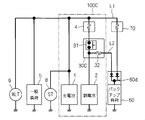
- FIG. 3 is a circuit diagram showing a first comparative example.
- the in-vehicle power supply device 100C includes a main battery 1, a sub battery 2, and a power supply box 30C.
- the main battery 1 is for in-vehicle use and is charged from the outside of the in-vehicle power supply device 100C. Specifically, the main battery 1 is connected to an on-vehicle alternator 9 and is charged by the power generation function of the alternator 9.
- a starter 8 is connected to the main battery 1 together with a general load 5 from the outside of the in-vehicle power supply device 100C.
- the general load 5 is a load that is not subject to backup of the sub-battery 2, and is, for example, an in-vehicle air conditioner.
- the starter 8 is a motor that starts an engine (not shown).
- the general load 5 and the starter 8 are well-known loads and do not have specific characteristics in the comparative example and the embodiment, and thus detailed description thereof is omitted.
- the backup load 60 is a load that is desired to maintain the power supply even when the power supply from the main battery 1 is lost.
- a shift-by-wire actuator or an electronically controlled braking force distribution system can be cited as an example. .
- the secondary battery 2 is for in-vehicle use and is charged by at least one of the alternator 9 and the main battery 1.
- a lead storage battery is used as the main battery 1
- a lithium ion battery is used as the sub battery 2, for example.
- Each of the main battery 1 and the sub battery 2 is a concept including a capacitor.
- an electric double layer capacitor may be employed for the sub battery 2.
- the in-vehicle power supply device 100C includes a fuse connected in series with the sub-battery 2 with a power supply box 30C (more specifically, a switch 31 described later) interposed therebetween. Is further provided. In the illustration of FIG. 3, the fuse is housed in the fuse box 4.
- the in-vehicle power supply device 100C supplies power to the backup load 60 via the main power supply path L1 and the sub power supply path L2.
- the main power supply path L1 connects the main battery 1, the general load 5, and the backup load 60 in parallel with a fixed potential point (here, ground). That is, both the general load 5 and the backup load 60 receive power via the main power supply path L1.
- the secondary power supply path L2 is connected to the power supply box 30C and is a path for supplying power from the secondary battery 2 to the backup load 60. Therefore, the backup load 60 can receive power not only from the main battery 1 through the main power supply path L1, but also from the sub battery 2 through the sub power supply path L2.
- FIG. 3 illustrates a case where the fuse on the main power supply path L1 is provided in the fuse box 70, and the fuse 32 on the sub power supply path L2 is provided in the power supply box 30C.
- the power supply box 30C houses the switch 31 and the fuse 32 described above.
- a relay can be adopted as the switch 31.
- the sub power feeding path L ⁇ b> 2 is drawn from the connection point between the sub battery 2 and the switch 31.
- the switch 31 When charging the secondary battery 2, the switch 31 is in the closed state, and when not charging, the closed / open state is selected according to the operation.
- a control device for example, an in-vehicle ECU (engine control unit).
- the occurrence of inter-battery recirculation can be avoided by the diode group 60d provided along with the backup load 60.
- both the main battery 1 and the sub battery 2 supply power to the backup load 60 at a potential higher than ground.
- the cathodes of the pair of diodes constituting the diode group 60d are arranged toward the backup load 60, and the anodes are arranged toward the main power supply path L1 and the sub power supply path L2, respectively.
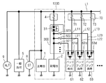
- FIG. 4 is a circuit diagram showing a second comparative example.
- the in-vehicle power supply device 100D includes a main battery 1, a sub battery 2, and a power supply box 30D.
- the second comparative example is provided with a plurality of backup loads 61, 62, 63,.
- the general load 5 receives power via the main power supply path L1 as in the first comparative example.
- the main power supply path L1 branches into power supply branches L11, L12, L13,..., And serves as power supply paths to the backup loads 61, 62, 63,.
- Fuses 71, 72, 73,... Corresponding to the power supply branches L11, L12, L13,.
- the fuses 71, 72, 73,... are illustrated as being housed in the fuse box 70.
- the in-vehicle power supply device 100D in the second comparative example has a configuration in which the power supply box 30C of the in-vehicle power supply device 100C in the first comparative example is replaced with a power supply box 30D.
- the power supply box 30D includes the switch 31 described in the first comparative example.
- the switch 31 is sandwiched between the secondary battery 2 and the fuse in the fuse box 4 and is connected in series.
- a plurality of sub-feeding paths L21, L22, L23,... are provided instead of the sub-feeding path L2 shown in the first comparative example, and these are supplied from the power supply box 30D in more detail. It is pulled out from the connection point between the sub battery 2 and the switch 31.
- the sub battery 2 supplies power to the backup loads 61, 62, 63,... Via the sub power feeding paths L21, L22, L23,.
- Fuses 321, 322, 323, In order to prevent overcurrent in the backup loads 61, 62, 63,..., Fuses 321, 322, 323,.
- FIG. 4 illustrates the case where the fuses 321, 322, 323,... Are housed in the power supply box 30D.
- the backup load 61 can receive power not only from the main battery 1 through the power supply branch L11 but also from the sub battery 2 through the sub power supply path L21. Therefore, a diode group 61d is provided in order to avoid the occurrence of inter-battery circulation in the backup load 61.
- the diode group 61d is also composed of a pair of diodes. Either of the pair of diodes has a cathode disposed toward the backup load 61, and an anode disposed toward the power supply branch L11 and the sub power supply path L21, respectively.
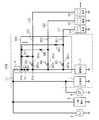
- FIG. 1 is a circuit diagram showing a connection relationship between backup loads 61, 62, 63,... And other general loads 5 and an in-vehicle power supply device 100A that supplies power to these.
- the in-vehicle power supply device 100A includes a main battery 1, a sub battery 2, and a power supply box 30A. Similar to the in-vehicle power supply devices 100C and 100D, the in-vehicle power supply device 100A preferably further includes a fuse connected in series with the auxiliary battery 2 with the power supply box 3 interposed therebetween. Here, the case where the said fuse is accommodated in the fuse box 4 similarly to the 1st comparative example and the 2nd comparative example is illustrated.
- the main battery 1 is charged by the power generation function of the alternator 9 from the outside of the in-vehicle power supply device 100A.
- a starter 8 is connected to the main battery 1 together with the general load 5 from the outside of the in-vehicle power supply device 100A.
- the general load 5 receives power via the main power supply path L1 as in the first comparative example and the second comparative example.
- the in-vehicle power supply device 100A in the present embodiment has a configuration in which the power supply box 30D of the in-vehicle power supply device 100D in the second comparative example is replaced with a power supply box 30A.
- the power supply box 30A includes the switch 31 described in the first comparative example and the second comparative example.
- the switch 31 has a pair of ends 31a and 31b.
- the end 31 a is connected to the main battery 1 through the fuse box 4.
- the end 31 b is connected to the sub battery 2.
- the main power supply path L1 connects the main battery 1 and the end 31a. From another point of view, the switch 31 is sandwiched between the secondary battery 2 and the fuse in the fuse box 4 and connected in series therewith.
- the sub battery 2 is connected to the main battery 1 and the main power supply path L1 via the switch 31.
- the sub battery 2 supplies power to the backup loads 61, 62, 63,... Via the sub power feeding paths L21, L22, L23,.
- the auxiliary power supply paths L21, L22, L23,... are provided with fuses 321, 322, 323,.
- FIG. 1 illustrates the case where the fuses 321, 322, 323,... Are housed in the power supply box 30A.
- the power supply box 30A includes a switch 31, fuses 321, 322, 323,... And a pair of contacts provided for each of the sub-feed paths L21, L22, L23,.
- relays 361, 362, 363,... are provided as contact pairs.
- the relay 361 has a first contact 361c and a second contact 361b
- the relay 362 has a first contact 362c and a second contact 362b
- the relay 363 has a first contact 363c and a second contact 363b, respectively.
- the second contacts 361b, 362b, 363b,... Are all connected to the end 31b.
- the relays 361, 362, 363,... are normally closed relays.
- the sub power feeding paths L21, L22, L23,... Connect the first contacts 361c, 362c, 363c,... And the backup loads 61, 62, 63,.
- the first contacts 361c, 362c, 363c,... Are connected to the auxiliary power feeding paths L21, L22, L23,.
- the first contacts 361c, 362c, 363c,... are also connected to the end 31a by a wiring 340. That is, the wiring 340 can be grasped as a connection path for connecting the end 31a and the first contacts 361c, 362c, 363c,... And supplying power from the main battery 1 to the backup loads 61, 62, 63,.
- the relays 361, 362, 363,... are normally set in a non-conductive state (open) by a control device (not shown), for example, an in-vehicle ECU (engine control unit). Therefore, if the switch 31 becomes non-conductive, normally from the main battery 1 via the auxiliary power supply paths L21, L22, L23,... From the first contacts 361c, 362c, 363c to the backup loads 61, 62, 63,. Power is supplied.
- the first contacts 361c, 362c, 363c are not connected to the sub battery 2, and the sub battery 2 is disconnected from the main battery 1 by the relays 361, 362, 363,.
- current circulation is avoided while securing power supply to the outside (here, backup loads 61, 62, 63,).
- the switch 31 and the relays 361, 362, 363,... are connected in parallel, when the switch 31 is conductive, the relays 361, 362, 363,. It does not matter which state is closed. Therefore, when the switch 31 is conducting, the control device may leave the relays 361, 362, 363,... In a closed state due to circumstances not considered here. In this case, the relays 361, 362, 363,... Are opened at the same time as the switch 31 is turned off or after a predetermined time has elapsed. This predetermined time can be set to a time at which the inter-battery reflux does not actually cause a problem, for example, the inter-battery reflux is small in potential difference between the main battery 1 and the sub-battery 2.
- the control device sets the relays 361, 362, 363,.
- the control device may not be able to set the relays 361, 362, 363,... Because both the alternator 9 and the main battery 1 have lost their power supply functions. However, if the relays 361, 362, 363,... Are normally closed, the relays 361, 362, 363,.
- the first contacts 361c, 362c, 363c, ... are connected to the second contacts 361b, 362b, 363b, ..., respectively, so that the auxiliary power supply path from the secondary battery 2 to the backup loads 61, 62, 63, ... Power is supplied via L21, L22, L23,.
- the power supply branches L11, L12, L13,... are not provided as in the second comparative example, so that the wiring is simplified and the fuses 71, 72, 73,. Specifically, the number of fuses is reduced by the number of backup loads as compared to the second comparative example.
- the relays 361, 362, 363 may be provided as individual relays, or the contact pairs may be realized by a plurality of relays.
- FIG. 2 is a circuit diagram showing a connection relationship between the backup loads 61, 62, 63,... And other general loads 5 and the in-vehicle power supply device 100B that supplies power to them.
- the in-vehicle power supply device 100B has a configuration in which the power supply box 30A is replaced with the power supply box 30B in the in-vehicle power supply device 100A described in the first embodiment.
- the power supply box 30B has a configuration in which diodes 341, 342, 343,.
- the anodes of the diodes 341, 342, 343,... Are connected to the end 31a.
- the cathodes of the diodes 341, 342, 343,... Are connected to the first contacts 361c, 362c, 363c,.
- the case where the positive electrode of the main battery 1 is connected to the end 31a and the positive electrode of the sub battery 2 is connected to the end 31b is illustrated.
- the diodes 341, 342, 343,... Can be grasped as connection paths for supplying power from the main battery 1 to the backup loads 61, 62, 63,. It can be said that a pair of first contacts 361c, 362c, 363c,... And second contacts 361b, 362b, 363b,... And diodes 341, 342, 343,.
- the connection path is different from the wiring 340 in that the power supply from the first contacts 361c, 362c, 363c,.
- the connection directions of the diodes 341, 342, 343, that is, the cathodes of the diodes 341, 342, 343,... Are connected to the end 31a, and the anodes thereof are connected to the first contacts 361c, 362c, 363c,.
Landscapes
- Engineering & Computer Science (AREA)
- Power Engineering (AREA)
- Mechanical Engineering (AREA)
- Charge And Discharge Circuits For Batteries Or The Like (AREA)
- Control Of Charge By Means Of Generators (AREA)
- Secondary Cells (AREA)
- Direct Current Feeding And Distribution (AREA)
Priority Applications (2)
| Application Number | Priority Date | Filing Date | Title |
|---|---|---|---|
| CN201680053608.8A CN108025690A (zh) | 2015-09-24 | 2016-09-12 | 车载用电源装置 |
| US15/761,451 US20190054870A1 (en) | 2015-09-24 | 2016-09-12 | In-vehicle power supply device |
Applications Claiming Priority (2)
| Application Number | Priority Date | Filing Date | Title |
|---|---|---|---|
| JP2015-186487 | 2015-09-24 | ||
| JP2015186487A JP2017061181A (ja) | 2015-09-24 | 2015-09-24 | 車載用電源装置 |
Publications (1)
| Publication Number | Publication Date |
|---|---|
| WO2017051741A1 true WO2017051741A1 (ja) | 2017-03-30 |
Family
ID=58386669
Family Applications (1)
| Application Number | Title | Priority Date | Filing Date |
|---|---|---|---|
| PCT/JP2016/076805 Ceased WO2017051741A1 (ja) | 2015-09-24 | 2016-09-12 | 車載用電源装置 |
Country Status (4)
| Country | Link |
|---|---|
| US (1) | US20190054870A1 (enExample) |
| JP (1) | JP2017061181A (enExample) |
| CN (1) | CN108025690A (enExample) |
| WO (1) | WO2017051741A1 (enExample) |
Families Citing this family (5)
| Publication number | Priority date | Publication date | Assignee | Title |
|---|---|---|---|---|
| JP2017121864A (ja) * | 2016-01-07 | 2017-07-13 | 株式会社オートネットワーク技術研究所 | 給電中継回路、副電池モジュール、電源システム |
| JP6540565B2 (ja) * | 2016-03-16 | 2019-07-10 | 株式会社オートネットワーク技術研究所 | 車両用電源供給システム、車両用駆動システム |
| DE102017218446A1 (de) * | 2016-10-28 | 2018-05-03 | Robert Bosch Gmbh | Verfahren zum Überwachen eines Kraftfahrzeugs mit automatisierter Fahrfunktion und Vorrichtung zum Durchführen des Verfahrens |
| CN115515522A (zh) * | 2020-06-01 | 2022-12-23 | 瑞德医疗机器股份有限公司 | 手术辅助装置 |
| JP7740937B2 (ja) * | 2021-09-01 | 2025-09-17 | 古河電気工業株式会社 | 電源システム |
Citations (3)
| Publication number | Priority date | Publication date | Assignee | Title |
|---|---|---|---|---|
| JP2002064946A (ja) * | 2000-08-11 | 2002-02-28 | Sony Corp | 電源装置 |
| JP2006033906A (ja) * | 2004-07-12 | 2006-02-02 | Denso Corp | 車両用電源回路 |
| JP2012080723A (ja) * | 2010-10-05 | 2012-04-19 | Auto Network Gijutsu Kenkyusho:Kk | 車両用電源装置 |
Family Cites Families (4)
| Publication number | Priority date | Publication date | Assignee | Title |
|---|---|---|---|---|
| JP5520629B2 (ja) * | 2010-02-12 | 2014-06-11 | 富士重工業株式会社 | 車両用電源装置 |
| JP5683408B2 (ja) * | 2011-08-09 | 2015-03-11 | トヨタ自動車株式会社 | 車両駆動用モータを有する自動車 |
| CN203312880U (zh) * | 2013-07-08 | 2013-11-27 | 任小波 | 一种电动车备用循环充电装置 |
| CN204340929U (zh) * | 2014-12-25 | 2015-05-20 | 东风汽车公司 | 一种汽车双蓄电池控制电路 |
-
2015
- 2015-09-24 JP JP2015186487A patent/JP2017061181A/ja active Pending
-
2016
- 2016-09-12 CN CN201680053608.8A patent/CN108025690A/zh active Pending
- 2016-09-12 WO PCT/JP2016/076805 patent/WO2017051741A1/ja not_active Ceased
- 2016-09-12 US US15/761,451 patent/US20190054870A1/en not_active Abandoned
Patent Citations (3)
| Publication number | Priority date | Publication date | Assignee | Title |
|---|---|---|---|---|
| JP2002064946A (ja) * | 2000-08-11 | 2002-02-28 | Sony Corp | 電源装置 |
| JP2006033906A (ja) * | 2004-07-12 | 2006-02-02 | Denso Corp | 車両用電源回路 |
| JP2012080723A (ja) * | 2010-10-05 | 2012-04-19 | Auto Network Gijutsu Kenkyusho:Kk | 車両用電源装置 |
Also Published As
| Publication number | Publication date |
|---|---|
| CN108025690A (zh) | 2018-05-11 |
| JP2017061181A (ja) | 2017-03-30 |
| US20190054870A1 (en) | 2019-02-21 |
Similar Documents
| Publication | Publication Date | Title |
|---|---|---|
| WO2017051736A1 (ja) | 車載用電源装置 | |
| US10549705B2 (en) | Switch device for on-board power supply and on-board power supply device | |
| CN106255622B (zh) | 用于将基础车载电网与尤其与安全相关的分网连接的装置 | |
| US10676053B2 (en) | Power source device | |
| US11104232B2 (en) | Safe energy supply device for a vehicle | |
| WO2017051741A1 (ja) | 車載用電源装置 | |
| US20190126866A1 (en) | Switch device for on-board power supply and on-board power supply system | |
| JP6569123B2 (ja) | 車載用電源装置 | |
| US20180262044A1 (en) | Battery storage system and on-board electrical system for supplying power in a fault-tolerant manner to safety-relevant loads in a vehicle | |
| JP6460875B2 (ja) | バッテリシステム制御装置 | |
| WO2017159485A1 (ja) | 車両用電源供給システム、車両用駆動システム | |
| DE102018210943A1 (de) | Bordnetz für ein Fahrzeug sowie Fahrzeug | |
| WO2017051812A1 (ja) | 車載用電源装置及びその制御方法 | |
| EP3137342A1 (de) | Vorrichtung zur versorgung zumindest eines verbrauchers | |
| JP2017052473A (ja) | 車載用電源装置 | |
| DE112017006265B4 (de) | Batterieeinheit und Leistungssystem | |
| DE102016224618A1 (de) | Fahrzeug-Bordnetz mit hoher Verfügbarkeit | |
| KR102593867B1 (ko) | 리던던트 전력 공급 시스템 및 방법 | |
| US20250135951A1 (en) | On-board electrical system for a motor vehicle and method for operating an on-board electrical system for a motor vehicle | |
| JP2015221595A (ja) | 自動車の電源装置 | |
| US12107418B2 (en) | System for the electric power supply of a vehicle | |
| KR20210047349A (ko) | 전력을 제공하기 위한 시스템 및 방법 |
Legal Events
| Date | Code | Title | Description |
|---|---|---|---|
| 121 | Ep: the epo has been informed by wipo that ep was designated in this application |
Ref document number: 16848529 Country of ref document: EP Kind code of ref document: A1 |
|
| NENP | Non-entry into the national phase |
Ref country code: DE |
|
| 122 | Ep: pct application non-entry in european phase |
Ref document number: 16848529 Country of ref document: EP Kind code of ref document: A1 |