WO2017051638A1 - 光学測定器 - Google Patents
光学測定器 Download PDFInfo
- Publication number
- WO2017051638A1 WO2017051638A1 PCT/JP2016/073992 JP2016073992W WO2017051638A1 WO 2017051638 A1 WO2017051638 A1 WO 2017051638A1 JP 2016073992 W JP2016073992 W JP 2016073992W WO 2017051638 A1 WO2017051638 A1 WO 2017051638A1
- Authority
- WO
- WIPO (PCT)
- Prior art keywords
- light
- guide path
- light guide
- measuring instrument
- optical measuring
- Prior art date
Links
Images

Classifications
-
- G—PHYSICS
- G01—MEASURING; TESTING
- G01N—INVESTIGATING OR ANALYSING MATERIALS BY DETERMINING THEIR CHEMICAL OR PHYSICAL PROPERTIES
- G01N21/00—Investigating or analysing materials by the use of optical means, i.e. using sub-millimetre waves, infrared, visible or ultraviolet light
- G01N21/17—Systems in which incident light is modified in accordance with the properties of the material investigated
- G01N21/25—Colour; Spectral properties, i.e. comparison of effect of material on the light at two or more different wavelengths or wavelength bands
- G01N21/31—Investigating relative effect of material at wavelengths characteristic of specific elements or molecules, e.g. atomic absorption spectrometry
-
- B—PERFORMING OPERATIONS; TRANSPORTING
- B01—PHYSICAL OR CHEMICAL PROCESSES OR APPARATUS IN GENERAL
- B01L—CHEMICAL OR PHYSICAL LABORATORY APPARATUS FOR GENERAL USE
- B01L9/00—Supporting devices; Holding devices
- B01L9/06—Test-tube stands; Test-tube holders
-
- G—PHYSICS
- G01—MEASURING; TESTING
- G01N—INVESTIGATING OR ANALYSING MATERIALS BY DETERMINING THEIR CHEMICAL OR PHYSICAL PROPERTIES
- G01N21/00—Investigating or analysing materials by the use of optical means, i.e. using sub-millimetre waves, infrared, visible or ultraviolet light
- G01N21/01—Arrangements or apparatus for facilitating the optical investigation
-
- G—PHYSICS
- G01—MEASURING; TESTING
- G01N—INVESTIGATING OR ANALYSING MATERIALS BY DETERMINING THEIR CHEMICAL OR PHYSICAL PROPERTIES
- G01N21/00—Investigating or analysing materials by the use of optical means, i.e. using sub-millimetre waves, infrared, visible or ultraviolet light
- G01N21/17—Systems in which incident light is modified in accordance with the properties of the material investigated
- G01N21/25—Colour; Spectral properties, i.e. comparison of effect of material on the light at two or more different wavelengths or wavelength bands
- G01N21/255—Details, e.g. use of specially adapted sources, lighting or optical systems
-
- B—PERFORMING OPERATIONS; TRANSPORTING
- B01—PHYSICAL OR CHEMICAL PROCESSES OR APPARATUS IN GENERAL
- B01L—CHEMICAL OR PHYSICAL LABORATORY APPARATUS FOR GENERAL USE
- B01L2300/00—Additional constructional details
- B01L2300/06—Auxiliary integrated devices, integrated components
- B01L2300/0627—Sensor or part of a sensor is integrated
- B01L2300/0663—Whole sensors
-
- B—PERFORMING OPERATIONS; TRANSPORTING
- B01—PHYSICAL OR CHEMICAL PROCESSES OR APPARATUS IN GENERAL
- B01L—CHEMICAL OR PHYSICAL LABORATORY APPARATUS FOR GENERAL USE
- B01L2300/00—Additional constructional details
- B01L2300/12—Specific details about materials
- B01L2300/123—Flexible; Elastomeric
-
- B—PERFORMING OPERATIONS; TRANSPORTING
- B01—PHYSICAL OR CHEMICAL PROCESSES OR APPARATUS IN GENERAL
- B01L—CHEMICAL OR PHYSICAL LABORATORY APPARATUS FOR GENERAL USE
- B01L2300/00—Additional constructional details
- B01L2300/18—Means for temperature control
- B01L2300/1805—Conductive heating, heat from thermostatted solids is conducted to receptacles, e.g. heating plates, blocks
- B01L2300/1827—Conductive heating, heat from thermostatted solids is conducted to receptacles, e.g. heating plates, blocks using resistive heater
-
- B—PERFORMING OPERATIONS; TRANSPORTING
- B01—PHYSICAL OR CHEMICAL PROCESSES OR APPARATUS IN GENERAL
- B01L—CHEMICAL OR PHYSICAL LABORATORY APPARATUS FOR GENERAL USE
- B01L2300/00—Additional constructional details
- B01L2300/18—Means for temperature control
- B01L2300/1838—Means for temperature control using fluid heat transfer medium
- B01L2300/1844—Means for temperature control using fluid heat transfer medium using fans
-
- G—PHYSICS
- G01—MEASURING; TESTING
- G01N—INVESTIGATING OR ANALYSING MATERIALS BY DETERMINING THEIR CHEMICAL OR PHYSICAL PROPERTIES
- G01N21/00—Investigating or analysing materials by the use of optical means, i.e. using sub-millimetre waves, infrared, visible or ultraviolet light
- G01N21/01—Arrangements or apparatus for facilitating the optical investigation
- G01N21/03—Cuvette constructions
- G01N21/0332—Cuvette constructions with temperature control
-
- G—PHYSICS
- G01—MEASURING; TESTING
- G01N—INVESTIGATING OR ANALYSING MATERIALS BY DETERMINING THEIR CHEMICAL OR PHYSICAL PROPERTIES
- G01N2201/00—Features of devices classified in G01N21/00
- G01N2201/02—Mechanical
- G01N2201/022—Casings
- G01N2201/0221—Portable; cableless; compact; hand-held
-
- G—PHYSICS
- G01—MEASURING; TESTING
- G01N—INVESTIGATING OR ANALYSING MATERIALS BY DETERMINING THEIR CHEMICAL OR PHYSICAL PROPERTIES
- G01N2201/00—Features of devices classified in G01N21/00
- G01N2201/06—Illumination; Optics
- G01N2201/064—Stray light conditioning
-
- G—PHYSICS
- G01—MEASURING; TESTING
- G01N—INVESTIGATING OR ANALYSING MATERIALS BY DETERMINING THEIR CHEMICAL OR PHYSICAL PROPERTIES
- G01N2201/00—Features of devices classified in G01N21/00
- G01N2201/08—Optical fibres; light guides
Definitions
- the present invention relates to an optical measuring instrument. More specifically, the present invention relates to a portable optical measuring instrument used as an absorbance measuring instrument or the like.
- Patent Document 1 As a kind of optical measuring instrument, for example, in Patent Document 1, light emitted from a light source is irradiated onto a measurement sample, and light transmitted through the measurement sample is condensed and reflected by an optical system having a complicated configuration.
- An absorbance measuring instrument that guides light to a light receiving unit and measures the concentration of a target substance in a measurement sample from the amount of light attenuation is disclosed.
- Such an absorbance measuring instrument has the advantage of being able to measure absorbance with high functionality and high accuracy.
- an optical measuring instrument such as an absorbance measuring instrument for the purpose of use for point-of-care testing.
- the optical system between the light source and the measurement unit where the measurement sample is arranged or between the measurement unit and the light receiving unit is simplified to It is conceivable to place the light receiving unit close to each other.
- the present invention has been made based on the circumstances as described above, and can be easily carried by being miniaturized, and can prevent light other than detection light from entering the light receiving unit.
- An object of the present invention is to provide an optical measuring instrument that can obtain a highly accurate measurement result.
- the optical measuring instrument includes a first light guide having a first light guide path formed by a linearly extending through-hole that allows measurement light from a light source to enter a measurement unit on which a measurement sample is disposed.
- An optical measuring instrument comprising:
- the second light guide path forming body is formed of a light-absorbing material.
- the first light guide path forming body is formed of a light-absorbing material.
- the light-absorbing material is preferably a light-absorbing elastic body, and the light-absorbing elastic body is a silicone in which a light-absorbing substance is dispersed.
- a resin is preferred.
- the second light guide path of the second light guide path forming body is positioned coaxially with the first light guide path of the first light guide path forming body.
- the optical measuring instrument of the present invention can be miniaturized by placing the light source and the light receiver close to each other and can be easily carried. Moreover, according to the optical measuring instrument of the present invention, since the second light guide path forming body is made of a light-absorbing material, light other than the detection light is absorbed by the wall surface surrounding the second light guide path. Thus, reflection and scattering of the light can be suppressed. As a result, according to the optical measuring instrument of the present invention, it is possible to irradiate only the detection light to the light receiving unit and obtain a highly accurate measurement result.
- FIG. 2 is a cross-sectional view taken along line AA in FIG.
- FIG. 3 is a sectional view taken along line BB in FIG.
- FIG. 3 is a sectional view taken along line CC in FIG. 2.
- FIG. 7 is a sectional view taken along line DD in FIG. 6.
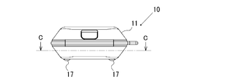
- FIG. 1 is a plan view showing an example of the configuration of the optical measuring instrument of the present invention
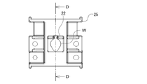
- FIG. 2 is a front view of the optical measuring instrument of FIG. 1
- FIG. 3 is a cross-sectional view taken along line AA in FIG. 1 is a sectional view taken along line BB in FIG. 1
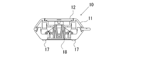
- FIG. 5 is a sectional view taken along line CC in FIG. 2
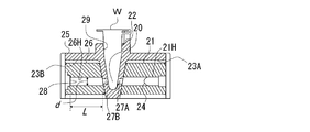
- FIG. 6 is a plan view showing an optical measuring mechanism in the optical measuring instrument of FIG. 7 and 7 are sectional views taken along the line DD in FIG.
- the optical measuring instrument 10 is used for measuring the concentration of a measurement target substance in a measurement sample as absorbance, and the measurement target substance is amplified by, for example, Escherichia coli, protein, polymerase chain reaction (PCR). The obtained DNA, dye, and the like.
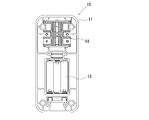
- an optical measuring mechanism 18 is provided in a region on the upper side (upper side in FIG. 1) in the housing 11, and in a region on the lower side (lower side in FIG. 1) in the housing 11,
- a battery chamber 19 is provided for housing the driving battery.
- a single-open lid 12 for inserting and removing the sample tube W is formed at a position corresponding to the optical measurement mechanism 18 on the upper surface side (left surface side in FIG. 4) of the housing 11.
- an operation unit 16 in which a power button and the like are arranged is formed in a lower region (lower portion in FIG. 1) on the upper surface side of the housing 11.
- a support leg 17 that supports the housing 11 on a horizontal support surface is provided on the lower surface side (the right surface side in FIG. 4) of the housing 11 so as to protrude.
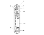
- the optical measurement mechanism 18 includes a first light guide path forming body 21 in which a first light guide path 21H for allowing measurement light from the light source 24 to enter the measurement unit 20 in which the sample tube W is disposed, And a second light guide path forming body 26 in which a second light guide path 26H for guiding the detection light emitted from the measurement section 20 to the light receiving section 28 is formed.
- the first light guide path 21H and the second light guide path 26H are each composed of a cylindrical through-hole extending linearly, and the first light guide path 21H and the second light guide path 26H are positioned coaxially with each other.
- the first light guide path forming body 21 and the second light guide path forming body 26 are arranged.
- the light source 24 is held in a state of being fitted to one end (the right end in FIG. 7) of the first light guide 21H that does not face the second light guide 26H.
- the light receiving unit 28 is held in a state of being fitted coaxially with the optical axis of the light source 24 at one end (left end in FIG. 7) of the second light guide 26H that does not face the first light guide 21H.
- the diameter of the first light guide path 21H on the light source 24 side may be the same as or different from the diameter of the second light guide path 26H on the light receiving section 28 side, but unnecessary scattered light and reflection. From the viewpoint of reducing light and stray light, the diameter of the second light guide path 26H on the light receiving unit 28 side is preferably smaller than the diameter of the first light guide path 21H on the light source 24 side.
- the optical measuring mechanism 18 is provided with a sample bracket 25 in which a sample tube W loaded with a measurement sample is inserted, and a tapered sample tube receiving hole 29 having a small diameter toward the bottom is formed at the center. Yes.
- a sample tube receiving hole 29 In the sample tube receiving hole 29, light passing holes 27A and 27B through which the measurement light and the detection light pass are formed in the lower side (lower side in FIG. 7) positions at positions facing each other.
- the sample tube receiving hole 29 is sandwiched so as to extend linearly in the left-right direction (left-right direction in FIG. 7) and communicate with the light passage holes 27A and 27B of the sample tube receiving hole 29. Containing recesses 23A and 23B are formed.
- the first light guide path forming body 21 and the second light guide path forming body 26 are respectively lighted at the end portions of the first light guide path 21H and the second light guide path 26H. It is held in a press-fitted state so as to face and communicate with the passage holes 27A and 27B. Further, the sample bracket 25 is formed with a position restricting member 22 that restricts the position of the sample tube W so as to protrude from the surface of the sample bracket 25 (the upper surface in FIG. 7).
- the sample tube receiving hole 29 can have a shape and a size corresponding to a PCR tube or a sample tube, for example, a 1.5 mL sample tube or a 2.0 mL sample tube.
- sample bracket 25 for example, one made of polycarbonate resin can be used.
- the sample bracket 25 is preferably black from the viewpoint of suppressing the incidence of stray light from the outside.
- the 1st light guide path formation body 21 and the 2nd light guide path formation body 26 are formed from the material which has a light absorptivity, and have a light absorptivity especially. It is preferable to consist of an elastic body.
- an elastic body having a light absorption property a silicone resin such as polydimethylsiloxane (PDMS) in which a light absorption material is dispersed can be used. Silicone resin can be preferably used as an elastic body having light absorption according to the present invention because autofluorescence itself is small.
- PDMS polydimethylsiloxane
- Silicone resin can be preferably used as an elastic body having light absorption according to the present invention because autofluorescence itself is small.
- the light-absorbing substance for example, a black powder can be used, and examples of the black powder include carbon black and carbon nanotubes.
- the refractive index of the elastic body in which the light-absorbing substance is dispersed is preferably 1.3 or more and 1.8 or less.
- the ratio L / d is preferably 3 or more and 15 or less, more preferably 3 3 or more and 13.3 or less.
- the ratio L / d between the diameter and the length of the second light guide 26H is 3 or less, scattered light other than the intended light detection light is sufficiently absorbed by the wall surface surrounding the second light guide 26H. Cannot be removed.
- the ratio L / d between the diameter and the length of the second light guide path 26H is 15 or more, the length L of the second light guide path 26H is increased, thereby sufficiently reducing the size of the optical measuring instrument. May not be possible.
- the capacity of the power source for energizing the light source 24 must be increased, the power source becomes larger, and optical measurement is performed. In some cases, it is not possible to reduce the size of the vessel sufficiently.
- the diameter d of the second light guide path 26H is, for example, 1.5 to 3 mm.
- the diameters of the first light guide path 21H and the second light guide path 26H are larger than the diameters of the light passage holes 27A and 27B of the sample bracket 25, respectively.
- the first light guide path forming body 21 and the second light guide path forming body 26 are press-fitted and held in the sample bracket 25.
- 27A and 27B can be reliably positioned within the openings of the first light guide 21H and the second light guide 26H.
- the length L of the second light guide 26H refers to the length along the central axis of the second light guide 26H. Further, the length L of the second light guide path 26H varies depending on the thickness of the light passage hole 27B of the sample bracket 25 (the thickness in the left-right direction in FIG. 7). Specifically, the length along the optical axis from the sample tube W to the light receiving unit 28 is 10 to 20 mm.
- An LED such as a white LED can be used as the light source 24, and a photodiode such as an RGB color sensor can be used as the light receiving unit 28, for example.
- a photodiode such as an RGB color sensor
- absorbance at each wavelength of RGB can be measured.
- the protein concentration can be quantified by the BCA method from the absorbance of light in the vicinity of a wavelength of 560 nm or by the Bradford method from the absorbance of light in the vicinity of a wavelength of 600 to 700 nm.
- the optical measuring instrument 10 of the present invention is provided with a heating mechanism for heating the measurement sample in the sample tube W for chemical or physical heat treatment or for optical measurement under a certain temperature condition. May be.
- the heating mechanism can heat the sample tube W from above and below.
- an upper heater member provided on the back surface side of the lid 12 of the housing 11 and arranged so as to be in contact with the upper surface of the sample tube W when the lid 12 is closed, and the sample The lower heater member arranged so as to contact the lower surface of the sample tube W protruding from the hole penetrating the lower portion of the tube receiving hole 29 can be used.
- Each of the upper heater member and the lower heater member can be a sheet heater having a pattern.
- the optical measuring instrument 10 of the present invention is provided with a heating mechanism, it is preferable that a cooling fan for rapidly cooling the heated sample tube W with circulating cooling air is further provided.
- the casing 11 has a vertical width (vertical length in FIG. 1) of 150 mm, a horizontal width (horizontal length in FIG. 1) of 70 mm, and a height (FIG. 1). In the direction perpendicular to the paper surface) is 30 mm, and the weight is 300 g.
- the diameter d of the second light guide path 26H is ⁇ 3.0 mm
- the length L in the optical axis direction is 11.2 mm
- the distance from the wall surface of the sample tube W to the surface of the light receiving unit 28 is 12.8 mm.
- the diameter of the light passage hole 27B of the sample tube receiving hole 29 in the sample bracket 25 is ⁇ 1.7 mm, and the diameter of the sample tube receiving hole 29 is ⁇ 1.7 mm and the maximum portion is ⁇ 3.0 mm. Furthermore, the distance between the light source 24 and the light receiving unit 28 is 35 mm.
- Optical measurement in the optical measuring instrument 10 is performed as follows. That is, in the optical measurement mechanism 18, the measurement light emitted from the light source 24 is irradiated to the liquid measurement sample in the sample tube W received in the sample tube receiving hole 29 in the measurement unit 20. The measurement light irradiated on the measurement sample in the sample tube W is absorbed according to the concentration of the measurement target substance. Of the light emitted through the sample tube W without being absorbed, scattered light other than the desired light detection light is absorbed and removed by the wall surface surrounding the second light guide path 26H, and only the detection light is detected. Reaches the light receiving unit 28, the amount of light is measured, the absorbance is obtained, and the concentration is calculated.
- the transmittance is exponentially attenuated with respect to the optical path length in accordance with the concentration of the measurement target substance. Therefore, calculate the concentration from the absorbance of the measurement target substance in the measurement sample by preparing a calibration curve by measuring a standard solution of the measurement target substance with a known concentration in advance as a reference sample and comparing it with the amount of light. Can do.
- the optical measuring instrument 10 described above can be miniaturized and easily carried by placing the light source 24 and the light receiver 28 close to each other.
- the optical measuring instrument 10 since the second light guide path forming body 26 is made of a light-absorbing material, scattering other than the intended detection light on the wall surface surrounding the second light guide path 26H. When light is absorbed, reflection and scattering of the light can be suppressed. As a result, according to the optical measuring instrument 10 of the present invention, it is possible to irradiate only the detection light to the light receiving unit 28 and obtain a highly accurate measurement result.
- the sample bracket is not essential, and the sample tube may be directly inserted into and removed from the light guide path forming body.
- the light guide path forming body is formed of an elastic body, it may be difficult to insert and remove because the friction with the polypropylene sample tube is large. Therefore, in the optical measuring instrument of the present invention, it is preferable to provide a sample bracket.
Landscapes
- Physics & Mathematics (AREA)
- Chemical & Material Sciences (AREA)
- Health & Medical Sciences (AREA)
- Biochemistry (AREA)
- Life Sciences & Earth Sciences (AREA)
- Analytical Chemistry (AREA)
- Spectroscopy & Molecular Physics (AREA)
- General Health & Medical Sciences (AREA)
- General Physics & Mathematics (AREA)
- Immunology (AREA)
- Pathology (AREA)
- Clinical Laboratory Science (AREA)
- Chemical Kinetics & Catalysis (AREA)
- Investigating Or Analysing Materials By Optical Means (AREA)
Abstract
小型化が図られて容易に持ち運ぶことができ、かつ、検出用光以外の光が受光部に入射することを抑制することができて高い精度の測定結果を得ることができる光学測定器を提供することを課題とする。 光学測定器は、測定試料が配置される測定部に光源からの測定用光を入射させる、直線状に伸びる貫通孔よりなる第1の導光路が内部に形成された第1の導光路形成体と、前記測定部から出射される検出用光を受光部に導光する、直線状に伸びる貫通孔よりなる第2の導光路が内部に形成された第2の導光路形成体とを有する光学測定器であって、前記第2の導光路形成体が、光吸収性を有する材料より形成されていることを特徴とする。
Description
本発明は、光学測定器に関する。更に詳しくは、吸光度測定器などとして用いられる可搬式の光学測定器に関する。
光学測定器の或る種のものとして、例えば特許文献1には、光源から出射した光を測定試料に照射し、当該測定試料を透過した光を複雑な構成の光学系によって集光、反射させて受光部に導光し、光の減衰量から測定試料中の目的物質の濃度を測定する吸光度測定器が開示されている。
このような吸光度測定器は、高機能であって高い精度の吸光度を測定することができるという利点を有する。
このような吸光度測定器は、高機能であって高い精度の吸光度を測定することができるという利点を有する。
一方、近年、ライフサイエンス分野では、ポイントオブケア検査に用いることなどを目的に、吸光度測定器などの光学測定器について、持ち運びを容易にするために小型化の要請がある。
そして、上記のような吸光度測定器について小型化を図る場合は、例えば光源と測定試料が配置される測定部との間や、測定部と受光部との間の光学系を簡略化して光源と受光部とを接近配置させることが考えられる。
そして、上記のような吸光度測定器について小型化を図る場合は、例えば光源と測定試料が配置される測定部との間や、測定部と受光部との間の光学系を簡略化して光源と受光部とを接近配置させることが考えられる。
しかしながら、光源から放射される光は発散光であるため、導光路を包囲する壁面において測定試料を透過した検出用光以外の光の反射、散乱が生じてしまう。その結果、受光部に対して、測定試料を透過して直進する検出用光だけでなく、導光路を包囲する壁面において反射、散乱された光が照射されることとなり、測定誤差が生じて高い精度の測定結果を得ることができない、という問題がある。
本発明は、以上のような事情に基づいてなされたものであって、小型化が図られて容易に持ち運ぶことができ、かつ、検出用光以外の光が受光部に入射することを抑制することができて高い精度の測定結果を得ることができる光学測定器を提供することを目的とする。
本発明の光学測定器は、測定試料が配置される測定部に光源からの測定用光を入射させる、直線状に伸びる貫通孔よりなる第1の導光路が内部に形成された第1の導光路形成体と、前記測定部から出射される検出用光を受光部に導光する、直線状に伸びる貫通孔よりなる第2の導光路が内部に形成された第2の導光路形成体とを有する光学測定器であって、
前記第2の導光路形成体が、光吸収性を有する材料より形成されていることを特徴とする。
前記第2の導光路形成体が、光吸収性を有する材料より形成されていることを特徴とする。
本発明の光学測定器においては、前記第1の導光路形成体が、光吸収性を有する材料より形成されていることが好ましい。
本発明の光学測定器においては、前記光吸収性を有する材料が、光吸収性を有する弾性体であることが好ましく、前記光吸収性を有する弾性体が、光吸収性物質が分散されたシリコーン樹脂であることが好ましい。
本発明の光学測定器においては、前記第2の導光路形成体の第2の導光路の径をd、長さをLとしたとき、下記関係式(1)を満足することが好ましい。
関係式(1):3≦L/d≦15
関係式(1):3≦L/d≦15
本発明の光学測定器においては、前記第2の導光路形成体の第2の導光路は、前記第1の導光路形成体の第1の導光路と同軸上に位置されていることが好ましい。
本発明の光学測定器は、光源と受光器とを近接配置させることにより小型化が図られ、容易に持ち運ぶことができる。しかも、本発明の光学測定器によれば、第2の導光路形成体が光吸収性を有する材料よりなるので、第2の導光路を包囲する壁面において検出用光以外の光が吸収されることにより当該光の反射、散乱を抑制することができる。その結果、本発明の光学測定器によれば、受光部に対して検出用光のみを照射させることができて高い精度の測定結果を得ることができる。
以下、本発明の実施の形態について詳細に説明する。
図1は、本発明の光学測定器の構成の一例を示す平面図、図2は、図1の光学測定器の正面図、図3は、図1におけるA-A線断面図、図4は、図1におけるB-B線断面図、図5は、図2におけるC-C線断面図、図6は、図1の光学測定器における光学測定機構を試料チューブが装着された状態で示す平面図、図7は、図6におけるD-D線断面図である。
この光学測定器10は、測定試料における測定対象物質の濃度などを吸光度として測定するためなどに用いられるものであり、測定対象物質は、例えば大腸菌、タンパク質、ポリメラーゼ連鎖反応(PCR)によって増幅されて得られたDNAや、色素などである。
図1は、本発明の光学測定器の構成の一例を示す平面図、図2は、図1の光学測定器の正面図、図3は、図1におけるA-A線断面図、図4は、図1におけるB-B線断面図、図5は、図2におけるC-C線断面図、図6は、図1の光学測定器における光学測定機構を試料チューブが装着された状態で示す平面図、図7は、図6におけるD-D線断面図である。
この光学測定器10は、測定試料における測定対象物質の濃度などを吸光度として測定するためなどに用いられるものであり、測定対象物質は、例えば大腸菌、タンパク質、ポリメラーゼ連鎖反応(PCR)によって増幅されて得られたDNAや、色素などである。
この光学測定器10は、光学測定機構18が筺体11内における上部側(図1における上部側)の領域に設けられると共に、筺体11内の下部側(図1における下部側)の領域には、駆動用電池を収容する電池室19が設けられている。また、筺体11の上面側(図4における左面側)における光学測定機構18に対応する位置には、試料チューブWを挿抜するための片開きの蓋12が形成されている。また、筺体11の上面側の下部(図1における下部)領域には、電源ボタンなどが配置された操作部16が形成されている。さらに、筺体11の下面側(図4における右面側)には、筺体11を水平な支持面上に支持する支持脚17が突出するよう設けられている。
光学測定機構18は、試料チューブWが配置される測定部20に光源24からの測定用光を入射させる第1の導光路21Hが内部に形成された第1の導光路形成体21と、当該測定部20から出射される検出用光を受光部28に導光する第2の導光路26Hが内部に形成された第2の導光路形成体26とを有する。
第1の導光路21Hおよび第2の導光路26Hは、各々直線状に伸びる円柱状の貫通孔よりなり、第1の導光路21Hおよび第2の導光路26Hが互いに同軸上に位置される状態に、第1の導光路形成体21および第2の導光路形成体26が配置されている。
第1の導光路21Hおよび第2の導光路26Hは、各々直線状に伸びる円柱状の貫通孔よりなり、第1の導光路21Hおよび第2の導光路26Hが互いに同軸上に位置される状態に、第1の導光路形成体21および第2の導光路形成体26が配置されている。
光源24は、第1の導光路21Hにおける第2の導光路26Hと対向しない一端(図7において右端)に嵌入された状態で保持される。また、受光部28は、第2の導光路26Hにおける第1の導光路21Hと対向しない一端(図7において左端)に、光源24の光軸と同軸状に嵌入された状態で保持される。
光源24が第1の導光路21Hに嵌入された状態で保持されることによって、光源24の光軸を概ね当該第1の導光路21Hの軸と並行に設定することが容易となり、従って、受光部28の方向に光束を高い効率で配光することができる。
光源24側の第1の導光路21Hの径は、受光部28側の第2の導光路26Hの径とで同じであってもよく、異なっていてもよいが、不必要な散乱光、反射光、迷光を低減させる観点から、受光部28側の第2の導光路26Hの径が光源24側の第1の導光路21Hの径よりも小さいことが好ましい。
光源24が第1の導光路21Hに嵌入された状態で保持されることによって、光源24の光軸を概ね当該第1の導光路21Hの軸と並行に設定することが容易となり、従って、受光部28の方向に光束を高い効率で配光することができる。
光源24側の第1の導光路21Hの径は、受光部28側の第2の導光路26Hの径とで同じであってもよく、異なっていてもよいが、不必要な散乱光、反射光、迷光を低減させる観点から、受光部28側の第2の導光路26Hの径が光源24側の第1の導光路21Hの径よりも小さいことが好ましい。
光学測定機構18には、測定試料が装填された試料チューブWが挿入される、底部に向かって小径となるテーパ状の試料チューブ受容穴29が中央部に形成された試料ブラケット25が設けられている。試料チューブ受容穴29には、下部側(図7において下部側)の領域に、測定用光および検出用光がそれぞれ通過する光通過穴27A,27Bが互いに対向する位置にそれぞれ形成されている。この試料ブラケット25内には、試料チューブ受容穴29を挟んで左右方向(図7において左右方向)に直線状に伸び、かつ、当該試料チューブ受容穴29の光通過穴27A,27Bに連通するよう収容用凹所23A,23Bが形成されている。そして、この収容用凹所23A,23Bに、それぞれ第1の導光路形成体21および第2の導光路形成体26が、第1の導光路21Hおよび第2の導光路26Hの端部が光通過穴27A,27Bとそれぞれ対向して連通するよう、圧入された状態で保持されている。
また、試料ブラケット25には、試料チューブWの位置を規制する位置規制部材22が、試料ブラケット25の表面(図7において上面)から突出する状態に形成されている。
また、試料ブラケット25には、試料チューブWの位置を規制する位置規制部材22が、試料ブラケット25の表面(図7において上面)から突出する状態に形成されている。
試料チューブ受容穴29は、PCRチューブ、または、試料チューブ、例えば1.5mLの試料チューブ若しくは2.0mLの試料チューブに対応する形状および大きさとすることができる。
試料ブラケット25としては、例えばポリカーボネート樹脂からなるものを用いることができる。
試料ブラケット25は、外部からの迷光の入射を抑止する観点から、黒色であることが好ましい。
試料ブラケット25は、外部からの迷光の入射を抑止する観点から、黒色であることが好ましい。
そして、本発明の光学測定器10においては、第1の導光路形成体21および第2の導光路形成体26は、光吸収性を有する材料より形成されており、特に、光吸収性を有する弾性体からなることが好ましい。
光吸収性を有する弾性体としては、光吸収性物質が分散された、ポリジメチルシロキサン(PDMS)などのシリコーン樹脂を用いることができる。シリコーン樹脂は自らが蛍光を発する自家蛍光が小さいという理由から、本発明に係る光吸収性を有する弾性体として好ましく用いることができる。
光吸収性物質としては、例えば黒色の粉末を用いることができ、黒色の粉末としては、カーボンブラックやカーボンナノチューブなどが挙げられる。
光吸収性物質が分散される弾性体の屈折率は、1.3以上1.8以下であることが好ましい。
光吸収性を有する弾性体としては、光吸収性物質が分散された、ポリジメチルシロキサン(PDMS)などのシリコーン樹脂を用いることができる。シリコーン樹脂は自らが蛍光を発する自家蛍光が小さいという理由から、本発明に係る光吸収性を有する弾性体として好ましく用いることができる。
光吸収性物質としては、例えば黒色の粉末を用いることができ、黒色の粉末としては、カーボンブラックやカーボンナノチューブなどが挙げられる。
光吸収性物質が分散される弾性体の屈折率は、1.3以上1.8以下であることが好ましい。
第2の導光路形成体26の第2の導光路26Hの径をd、長さをLとしたとき、これらの比L/dは、3以上15以下であることが好ましく、より好ましくは3.3以上13.3以下である。
第2の導光路26Hの径と長さとの比L/dが3以下である場合は、所期の光検出光以外の散乱光を、十分に第2の導光路26Hを包囲する壁面によって吸収して除去することができないおそれがある。一方、第2の導光路26Hの径と長さとの比L/dが15以上である場合は、第2の導光路26Hの長さLが大きくなることにより、光学測定器の十分な小型化を図ることができない場合がある。また、第2の導光路26Hの径dが小さくなることで、光源24の光量を高める必要があるため、光源24に通電する電源の容量を増やさなければならず、電源が大型化し、光学測定器の十分な小型化を図ることができない場合がある。
第2の導光路26Hの径dは、例えば1.5~3mmである。
第1の導光路21Hおよび第2の導光路26Hの径は、それぞれ試料ブラケット25の光通過穴27A,27Bの径よりも大きいものとされている。これにより、第1の導光路形成体21および第2の導光路形成体26は試料ブラケット25に対して圧入されて保持されるが、これらに圧入による変形が生じた場合にも、光通過穴27A,27Bを確実に第1の導光路21Hおよび第2の導光路26Hの開口内に位置させることができる。
第2の導光路26Hの長さLは、当該第2の導光路26Hの中心軸に沿った長さをいう。
また、第2の導光路26Hの長さLは、試料ブラケット25の光通過穴27Bの厚み(図7における左右方向の厚み)によっても異なる。具体的には、試料チューブWから受光部28までの光軸に沿った長さが10~20mmとされる。
また、第2の導光路26Hの長さLは、試料ブラケット25の光通過穴27Bの厚み(図7における左右方向の厚み)によっても異なる。具体的には、試料チューブWから受光部28までの光軸に沿った長さが10~20mmとされる。
光源24としては、例えば白色LEDなどのLEDを用いることができ、受光部28としては、例えばRGBカラーセンサなどのフォトダイオードを用いることができる。受光部28としてRGBカラーセンサを用いることにより、RGBの各波長における吸光度を測定することができる。
例えば波長560nm付近の光の吸光度からBCA法によって、あるいは、波長600~700nm付近の光の吸光度からブラッドフォード法によって、たんぱく質の濃度を定量することができる。
例えば波長560nm付近の光の吸光度からBCA法によって、あるいは、波長600~700nm付近の光の吸光度からブラッドフォード法によって、たんぱく質の濃度を定量することができる。
本発明の光学測定器10には、試料チューブW内の測定試料を、化学的または物理的に加熱処理するため、または、一定の温度条件で光学測定するために加熱する加熱機構が設けられていてもよい。
加熱機構は、試料チューブWを上下から加熱するものとすることができる。具体的には、筺体11の蓋12の裏面側に設けられ、当該蓋12が閉状態とされることにより試料チューブWに押圧されてその上面に接触するよう配置された上部ヒーター部材と、試料チューブ受容穴29の下部に貫通された穴から突出した試料チューブWの下面に接触するよう配置された下部ヒーター部材とからなるものとすることができる。
上部ヒーター部材および下部ヒーター部材としては、各々、パターンを有するシートヒーターを用いることができる。
上部ヒーター部材および下部ヒーター部材としては、各々、パターンを有するシートヒーターを用いることができる。
本発明の光学測定器10に加熱機構が設けられる場合においては、さらに、加熱された試料チューブWを循環冷却風によって急速に冷却する冷却用ファンが設けられていることが好ましい。
光学測定器10の各部の寸法の一例を挙げると、筺体11は、縦幅(図1における上下方向長さ)が150mm、横幅(図1における左右方向長さ)が70mm、高さ(図1における紙面と垂直な方向の長さ)が30mm、重さが300gである。また、第2の導光路26Hの径dがφ3.0mm、光軸方向の長さLが11.2mm、試料チューブWの壁面から受光部28の表面までの距離が12.8mmである。また、試料ブラケット25における試料チューブ受容穴29の光通過穴27Bの径はφ1.7mm、試料チューブ受容穴29の直径は、最小部がφ1.7mm、最大部がφ3.0mmである。さらに、光源24と受光部28との距離は35mmである。
光学測定器10における光学測定は、以下のように行われる。すなわち、光学測定機構18において、光源24から出射した測定用光が、測定部20において試料チューブ受容穴29に受容された試料チューブW内の液体状の測定試料に照射される。試料チューブW内の測定試料に照射された測定用光は、測定対象物質の濃度に応じて吸収される。吸収されずに試料チューブWを透過して出射された光のうち、所期の光検出光以外の散乱光は第2の導光路26Hを包囲する壁面によって吸収されて除去され、検出用光のみが受光部28に至り、その光量が測定されて吸光度が取得されて濃度が算出される。具体的には、光が測定試料を透過する際、その透過率が測定対象物質の濃度に応じて光路長に対して指数関数的に減衰する。従って、予め既知の濃度の測定対象物質の標準溶液を基準試料として測定して検量線を作成しておき、その光量と比較することにより、測定試料における測定対象物質の吸光度から濃度を算出することができる。
以上の光学測定器10は、光源24と受光器28とを近接配置させることにより小型化が図られ、容易に持ち運ぶことができる。しかも、この光学測定器10によれば、第2の導光路形成体26が光吸収性を有する材料よりなるので、第2の導光路26Hを包囲する壁面における所期の検出用光以外の散乱光が吸収されることにより当該光の反射、散乱を抑制することができる。その結果、本発明の光学測定器10によれば、受光部28に対して検出用光のみを照射させることができて高い精度の測定結果を得ることができる。
以上、本発明の実施の形態について説明したが、本発明は上記の実施の形態に限定されるものではなく、種々の変更を加えることができる。
例えば、試料ブラケットは必須のものではなく、導光路形成体に対して、試料チューブを直接挿抜する構成であってもよい。しかしながら、導光路形成体が弾性体によって形成されている場合は、ポリプロピレン製の試料チューブとの間の摩擦が大きいために挿抜しにくいことがある。従って、本発明の光学測定器においては、試料ブラケットが設けられることが好ましい。
例えば、試料ブラケットは必須のものではなく、導光路形成体に対して、試料チューブを直接挿抜する構成であってもよい。しかしながら、導光路形成体が弾性体によって形成されている場合は、ポリプロピレン製の試料チューブとの間の摩擦が大きいために挿抜しにくいことがある。従って、本発明の光学測定器においては、試料ブラケットが設けられることが好ましい。
10 光学測定器
11 筺体
12 蓋
16 操作部
17 支持脚
18 光学測定機構
19 電池室
20 測定部
21 第1の導光路形成体
21H 第1の導光路
22 位置規制部材
23A,23B 収容用凹所
24 光源
25 試料ブラケット
26 第2の導光路形成体
26H 第2の導光路
27A,27B 光通過穴
28 受光部
29 試料チューブ受容穴
W 試料チューブ
11 筺体
12 蓋
16 操作部
17 支持脚
18 光学測定機構
19 電池室
20 測定部
21 第1の導光路形成体
21H 第1の導光路
22 位置規制部材
23A,23B 収容用凹所
24 光源
25 試料ブラケット
26 第2の導光路形成体
26H 第2の導光路
27A,27B 光通過穴
28 受光部
29 試料チューブ受容穴
W 試料チューブ
Claims (6)
- 測定試料が配置される測定部に光源からの測定用光を入射させる、直線状に伸びる貫通孔よりなる第1の導光路が内部に形成された第1の導光路形成体と、前記測定部から出射される検出用光を受光部に導光する、直線状に伸びる貫通孔よりなる第2の導光路が内部に形成された第2の導光路形成体とを有する光学測定器であって、
前記第2の導光路形成体が、光吸収性を有する材料より形成されていることを特徴とする光学測定器。 - 前記第1の導光路形成体が、光吸収性を有する材料より形成されていることを特徴とする請求項1に記載の光学測定器。
- 前記光吸収性を有する材料が、光吸収性を有する弾性体であることを特徴とする請求項1または請求項2に記載の光学測定器。
- 前記光吸収性を有する弾性体が、光吸収性物質が分散されたシリコーン樹脂であることを特徴とする請求項3に記載の光学測定器。
- 前記第2の導光路形成体の第2の導光路の径をd、長さをLとしたとき、下記関係式(1)を満足することを特徴とする請求項1乃至請求項4のいずれかに記載の光学測定器。
関係式(1):3≦L/d≦15 - 前記第2の導光路形成体の第2の導光路は、前記第1の導光路形成体の第1の導光路と同軸上に位置されていることを特徴とする請求項1乃至請求項5のいずれかに記載の光学測定器。
Priority Applications (2)
| Application Number | Priority Date | Filing Date | Title |
|---|---|---|---|
| CN201680055549.8A CN108139324B (zh) | 2015-09-25 | 2016-08-17 | 光学测定器 |
| US15/933,053 US10809185B2 (en) | 2015-09-25 | 2018-03-22 | Optical measuring device |
Applications Claiming Priority (2)
| Application Number | Priority Date | Filing Date | Title |
|---|---|---|---|
| JP2015-187762 | 2015-09-25 | ||
| JP2015187762A JP6433398B2 (ja) | 2015-09-25 | 2015-09-25 | 光学測定器 |
Related Child Applications (1)
| Application Number | Title | Priority Date | Filing Date |
|---|---|---|---|
| US15/933,053 Continuation US10809185B2 (en) | 2015-09-25 | 2018-03-22 | Optical measuring device |
Publications (1)
| Publication Number | Publication Date |
|---|---|
| WO2017051638A1 true WO2017051638A1 (ja) | 2017-03-30 |
Family
ID=58386137
Family Applications (1)
| Application Number | Title | Priority Date | Filing Date |
|---|---|---|---|
| PCT/JP2016/073992 WO2017051638A1 (ja) | 2015-09-25 | 2016-08-17 | 光学測定器 |
Country Status (5)
| Country | Link |
|---|---|
| US (1) | US10809185B2 (ja) |
| JP (1) | JP6433398B2 (ja) |
| CN (1) | CN108139324B (ja) |
| TW (1) | TWI662268B (ja) |
| WO (1) | WO2017051638A1 (ja) |
Cited By (3)
| Publication number | Priority date | Publication date | Assignee | Title |
|---|---|---|---|---|
| WO2019009209A1 (ja) * | 2017-07-04 | 2019-01-10 | 国立大学法人九州大学 | 光測定装置、導光部材及び光測定方法 |
| JP2019015708A (ja) * | 2017-07-04 | 2019-01-31 | 国立大学法人九州大学 | 光測定装置、導光部材及び光測定方法 |
| TWI728885B (zh) * | 2020-07-30 | 2021-05-21 | 思創影像科技股份有限公司 | 導光模組與應用此導光模組之生物檢測設備 |
Families Citing this family (1)
| Publication number | Priority date | Publication date | Assignee | Title |
|---|---|---|---|---|
| CN112437877A (zh) * | 2018-09-11 | 2021-03-02 | 优志旺电机株式会社 | 酶标仪 |
Citations (2)
| Publication number | Priority date | Publication date | Assignee | Title |
|---|---|---|---|---|
| JP2006300741A (ja) * | 2005-04-21 | 2006-11-02 | Rohm Co Ltd | 光学測定用マイクロ流路及びマイクロ流体チップ |
| JP2015083962A (ja) * | 2013-09-20 | 2015-04-30 | 国立大学法人九州大学 | 光測定装置、光測定方法、フィルタ部材及びフィルタ部材を生産する方法 |
Family Cites Families (18)
| Publication number | Priority date | Publication date | Assignee | Title |
|---|---|---|---|---|
| US4609991A (en) * | 1983-07-19 | 1986-09-02 | The United States Of America As Represented By The Department Of Health And Human Services | Automated system for determining the molecular weight and/or concentration of macromolecules via sedimentation equilibrium |
| WO1997019340A1 (en) * | 1995-11-21 | 1997-05-29 | Cme Telemetrix Inc. | Apparatus and method for rapid spectrophotometric pre-test screen of specimen for a blood analyzer |
| JP3688068B2 (ja) * | 1996-08-29 | 2005-08-24 | シスメックス株式会社 | 液体試料測定装置 |
| US6992759B2 (en) * | 2002-10-21 | 2006-01-31 | Nippon Shokubai Co., Ltd. | Sample holder for spectrum measurement and spectrophotometer |
| CN2679854Y (zh) * | 2004-03-02 | 2005-02-16 | 肖剑鸣 | 微型通道光子倍增管 |
| US7375815B2 (en) * | 2004-10-12 | 2008-05-20 | Agilent Technologies, Inc. | Optical devices, systems and method for producing a collimated light path |
| CN1865927A (zh) * | 2006-05-18 | 2006-11-22 | 中国科学院安徽光学精密机械研究所 | 面污染源排放通量的被动差分吸收光谱测量方法与装置 |
| CN100381788C (zh) * | 2006-08-23 | 2008-04-16 | 北京航空航天大学 | 一种高精度低成本星光模拟器 |
| CN102859728A (zh) * | 2010-04-27 | 2013-01-02 | 信越化学工业株式会社 | 发光装置及发光装置的制造方法 |
| US8951472B2 (en) * | 2010-07-19 | 2015-02-10 | Andalyze, Inc. | Portable fluorimetric apparatus, method and system |
| CN102175690B (zh) * | 2011-01-24 | 2012-11-28 | 宁波大学 | 一种红外玻璃内部宏观缺陷检测装置 |
| CA2834790C (en) * | 2011-05-04 | 2019-04-09 | Luminex Corporation | Apparatus and methods for integrated sample preparation, reaction and detection |
| CN102954938B (zh) * | 2011-08-29 | 2014-08-27 | 中国科学院电子学研究所 | 基于微流控通道全反射集成光波导的吸收光度检测传感器 |
| KR101380368B1 (ko) * | 2012-09-18 | 2014-04-10 | 포항공과대학교 산학협력단 | 흡광 검출을 위한 흐름셀을 갖는 미세유체칩 및 이를 포함하는 흡광 검출 장치 |
| JP5947709B2 (ja) | 2012-12-27 | 2016-07-06 | 株式会社堀場製作所 | 分光分析方法及び分光分析装置 |
| US9488579B2 (en) * | 2013-01-22 | 2016-11-08 | Tecan Trading Ag | Optical measuring apparatus and method for the analysis of samples contained in liquid drops |
| CN103487144B (zh) * | 2013-08-29 | 2016-01-13 | 中国科学院长春光学精密机械与物理研究所 | 消杂光能力稳定的双光栅分光系统封装结构 |
| CN103762148B (zh) * | 2014-01-15 | 2016-03-02 | 山西长城微光器材股份有限公司 | 一种用于光电倍增管的微通道板 |
-
2015
- 2015-09-25 JP JP2015187762A patent/JP6433398B2/ja active Active
-
2016
- 2016-08-09 TW TW105125313A patent/TWI662268B/zh active
- 2016-08-17 WO PCT/JP2016/073992 patent/WO2017051638A1/ja active Application Filing
- 2016-08-17 CN CN201680055549.8A patent/CN108139324B/zh active Active
-
2018
- 2018-03-22 US US15/933,053 patent/US10809185B2/en active Active
Patent Citations (2)
| Publication number | Priority date | Publication date | Assignee | Title |
|---|---|---|---|---|
| JP2006300741A (ja) * | 2005-04-21 | 2006-11-02 | Rohm Co Ltd | 光学測定用マイクロ流路及びマイクロ流体チップ |
| JP2015083962A (ja) * | 2013-09-20 | 2015-04-30 | 国立大学法人九州大学 | 光測定装置、光測定方法、フィルタ部材及びフィルタ部材を生産する方法 |
Cited By (6)
| Publication number | Priority date | Publication date | Assignee | Title |
|---|---|---|---|---|
| WO2019009209A1 (ja) * | 2017-07-04 | 2019-01-10 | 国立大学法人九州大学 | 光測定装置、導光部材及び光測定方法 |
| JP2019015708A (ja) * | 2017-07-04 | 2019-01-31 | 国立大学法人九州大学 | 光測定装置、導光部材及び光測定方法 |
| CN110892249A (zh) * | 2017-07-04 | 2020-03-17 | 国立大学法人九州大学 | 光测定装置、导光部件以及光测定方法 |
| US11313798B2 (en) | 2017-07-04 | 2022-04-26 | Kyushu University, National University Corporation | Optical measuring device, light guide member, and optical measuring method |
| CN110892249B (zh) * | 2017-07-04 | 2024-01-02 | 国立大学法人九州大学 | 光测定装置、导光部件以及光测定方法 |
| TWI728885B (zh) * | 2020-07-30 | 2021-05-21 | 思創影像科技股份有限公司 | 導光模組與應用此導光模組之生物檢測設備 |
Also Published As
| Publication number | Publication date |
|---|---|
| JP6433398B2 (ja) | 2018-12-05 |
| JP2017062184A (ja) | 2017-03-30 |
| US20180217052A1 (en) | 2018-08-02 |
| CN108139324B (zh) | 2021-02-02 |
| US10809185B2 (en) | 2020-10-20 |
| TW201721126A (zh) | 2017-06-16 |
| TWI662268B (zh) | 2019-06-11 |
| CN108139324A (zh) | 2018-06-08 |
Similar Documents
| Publication | Publication Date | Title |
|---|---|---|
| WO2017051638A1 (ja) | 光学測定器 | |
| AU771677B2 (en) | Test element analysis system | |
| ES2689529T3 (es) | Sistema combinado indicador de esterilización, incubador y lector | |
| ES2910383T3 (es) | Un sistema de detección microfluídica y un cartucho microfluídico | |
| JP2009536339A5 (ja) | ||
| TWI656335B (zh) | Temperature control module and light measuring device | |
| US20190049370A1 (en) | Gas sensor and constant-temperature apparatus | |
| EP1923691A3 (en) | Long-term stable optical sensor arrangement, especially a hydrogen sensor, and combined gas sensor arrangement | |
| US20150014162A1 (en) | Connector for connecting bio-sensor and measuring instrument thereof | |
| JP6891391B2 (ja) | 光学測定器 | |
| FI118864B (fi) | Refraktometri | |
| WO2017098811A1 (ja) | 光測定装置 | |
| KR101873642B1 (ko) | 복합 가스 센서 | |
| US7372572B2 (en) | Device for photometrically measuring the concentration of a chemical substance in a solution to be measured | |
| KR102514582B1 (ko) | 단일 열원을 사용하여 가스 및 먼지를 감지하는 복합 센서 | |
| KR101617839B1 (ko) | 비분산 적외선 음주 측정기 | |
| JP6137270B2 (ja) | 光測定装置 | |
| JP2010151509A (ja) | センサチップ及びその使用方法 | |
| JP6578188B2 (ja) | 光学測定器 | |
| JP6691970B2 (ja) | 光学センサ装置 | |
| KR20100135060A (ko) | 광학적 가스센서 및 이를 포함하는 가스농도분석장치 | |
| JP6924439B2 (ja) | 光測定装置、導光部材及び光測定方法 | |
| JP6662010B2 (ja) | 光測定装置 | |
| JP2006275641A (ja) | 分光式ガスセンサ | |
| JP2019045149A (ja) | 機能水濃度センサ |
Legal Events
| Date | Code | Title | Description |
|---|---|---|---|
| 121 | Ep: the epo has been informed by wipo that ep was designated in this application |
Ref document number: 16848426 Country of ref document: EP Kind code of ref document: A1 |
|
| NENP | Non-entry into the national phase |
Ref country code: DE |
|
| 122 | Ep: pct application non-entry in european phase |
Ref document number: 16848426 Country of ref document: EP Kind code of ref document: A1 |