WO2017051631A1 - 故障診断装置、故障診断方法、及び故障診断プログラム - Google Patents
故障診断装置、故障診断方法、及び故障診断プログラム Download PDFInfo
- Publication number
- WO2017051631A1 WO2017051631A1 PCT/JP2016/073625 JP2016073625W WO2017051631A1 WO 2017051631 A1 WO2017051631 A1 WO 2017051631A1 JP 2016073625 W JP2016073625 W JP 2016073625W WO 2017051631 A1 WO2017051631 A1 WO 2017051631A1
- Authority
- WO
- WIPO (PCT)
- Prior art keywords
- failure
- unit
- installation environment
- information
- display
- Prior art date
- Legal status (The legal status is an assumption and is not a legal conclusion. Google has not performed a legal analysis and makes no representation as to the accuracy of the status listed.)
- Ceased
Links
Images


Classifications
-
- G—PHYSICS
- G16—INFORMATION AND COMMUNICATION TECHNOLOGY [ICT] SPECIALLY ADAPTED FOR SPECIFIC APPLICATION FIELDS
- G16H—HEALTHCARE INFORMATICS, i.e. INFORMATION AND COMMUNICATION TECHNOLOGY [ICT] SPECIALLY ADAPTED FOR THE HANDLING OR PROCESSING OF MEDICAL OR HEALTHCARE DATA
- G16H40/00—ICT specially adapted for the management or administration of healthcare resources or facilities; ICT specially adapted for the management or operation of medical equipment or devices
- G16H40/40—ICT specially adapted for the management or administration of healthcare resources or facilities; ICT specially adapted for the management or operation of medical equipment or devices for the management of medical equipment or devices, e.g. scheduling maintenance or upgrades
-
- G—PHYSICS
- G05—CONTROLLING; REGULATING
- G05B—CONTROL OR REGULATING SYSTEMS IN GENERAL; FUNCTIONAL ELEMENTS OF SUCH SYSTEMS; MONITORING OR TESTING ARRANGEMENTS FOR SUCH SYSTEMS OR ELEMENTS
- G05B23/00—Testing or monitoring of control systems or parts thereof
- G05B23/02—Electric testing or monitoring
-
- G—PHYSICS
- G05—CONTROLLING; REGULATING
- G05B—CONTROL OR REGULATING SYSTEMS IN GENERAL; FUNCTIONAL ELEMENTS OF SUCH SYSTEMS; MONITORING OR TESTING ARRANGEMENTS FOR SUCH SYSTEMS OR ELEMENTS
- G05B2219/00—Program-control systems
- G05B2219/30—Nc systems
- G05B2219/32—Operator till task planning
- G05B2219/32287—Medical, chemical, biological laboratory
-
- G—PHYSICS
- G05—CONTROLLING; REGULATING
- G05B—CONTROL OR REGULATING SYSTEMS IN GENERAL; FUNCTIONAL ELEMENTS OF SUCH SYSTEMS; MONITORING OR TESTING ARRANGEMENTS FOR SUCH SYSTEMS OR ELEMENTS
- G05B23/00—Testing or monitoring of control systems or parts thereof
- G05B23/02—Electric testing or monitoring
- G05B23/0205—Electric testing or monitoring by means of a monitoring system capable of detecting and responding to faults
- G05B23/0259—Electric testing or monitoring by means of a monitoring system capable of detecting and responding to faults characterized by the response to fault detection
- G05B23/0267—Fault communication, e.g. human machine interface [HMI]
Definitions
- the present invention relates to a failure diagnosis device, a failure diagnosis method, and a failure diagnosis program.
- Patent Document 1 discloses a failure location confirmation device that identifies the location of a failure that has occurred in a network.
- network devices are associated with customer information, and failure information is associated with a combination of network device states.
- this failure location confirmation apparatus receives the inquiry of a failure from a customer, the state of the network apparatus linked
- this failure location confirmation device it is possible to confirm failure information relating to a specific customer without examining the entire network by acquiring failure information associated with a combination of collected network device states. ing.
- Patent Document 2 discloses a detection system for detecting an abnormality sign of a mechanical facility.
- time-series data including sensor data is acquired as observation data from mechanical equipment, and normal data acquired in the past is clustered.
- a cluster having the smallest distance from the observation data is selected from the two or more clustered clusters, and an abnormality sign of the mechanical equipment is determined based on the distance between the selected cluster and the observation data. Is detected.
- the failure information to be acquired is limited to known information, and when sufficient failure information is not accumulated or an unknown failure occurs, a failure occurs. In many cases, it is not possible to extract the cause of the cause.
- Patent Document 2 detects a sign of equipment failure, and does not extract a cause of failure from a cluster obtained by clustering.
- the present invention has been made in view of the above circumstances, and provides a failure diagnosis device, a failure diagnosis method, and a failure diagnosis program capable of supporting the identification of the cause of failure in a device in which a failure has occurred. For the purpose.
- the failure diagnosis apparatus of the present invention includes an acquisition unit that acquires, for each of a plurality of devices, installation environment information including a plurality of items related to the installation environment in which each of the plurality of devices is installed. Based on the installation environment information, a classification unit that classifies a plurality of devices into a plurality of groups, and a group to which a device in which a failure occurs among a plurality of devices belongs, An extraction unit that extracts items and a display control unit that performs control to display an extraction result of the extraction unit on the display unit are provided.
- the classification unit may perform classification based on items that are candidates for the cause of the failure in the installation environment information.
- the display control unit may perform control to display the classification result by the classification unit on the display unit in a state where the classification result can be identified for each classified group.
- the display control unit may perform control to display the classification result on the display unit so that the device in which the failure has occurred can be identified.
- the failure diagnosis apparatus of the present invention further includes a storage unit that stores failure occurrence information in which failure information related to the type of failure that has occurred in the device and identification information assigned to each of the plurality of devices are associated with each other.
- the acquisition unit acquires failure information of the device in which the failure has occurred, and the display control unit, based on the failure occurrence information stored by the storage unit, the type of failure indicated by the failure information acquired by the acquisition unit You may perform control which displays a some group on a display part in the state which can identify the apparatus which the same kind of failure generate
- the installation environment information may include a plurality of items related to at least one of hardware related to the device to which the device is connected, software used in the device, and maintenance of the device. .
- the extraction unit may extract items of installation environment information representing each of a plurality of features in order from the feature having the highest degree of difference.
- the failure diagnosis apparatus of the present invention further includes a reception unit that receives input of installation environment information of a device in which a failure has occurred, and the classification unit uses the acquisition unit based on the installation environment information received by the reception unit.
- a device in which a failure has occurred may be classified into any of a plurality of groups classified based on the acquired installation environment information.
- the device may be a medical device.
- the failure diagnosis method of the present invention acquires installation environment information including a plurality of items related to the installation environment in which each of the plurality of devices is installed for each of the plurality of devices, and installs them. Based on the environment information, classify multiple devices into multiple groups, and extract the items of installation environment information that represent different features from other groups for the group to which the failed device belongs. The control is performed to display the extraction result on the display unit.
- the failure diagnosis program of the present invention is for causing a computer to function as an acquisition unit, a classification unit, an extraction unit, and a display control unit of the failure diagnosis apparatus of the present invention.
- a failure diagnosis apparatus 10A is provided in a facility 12, and is connected to a network 16 such as a WAN (Wide Area Network) via a network 14 such as a LAN (Local Area Network). It is connected.
- a network 16 such as a WAN (Wide Area Network)
- a network 14 such as a LAN (Local Area Network). It is connected.
- each of the facilities 18A to 18C a plurality of medical devices 20 to be diagnosed by the failure diagnosis device 10A and a management device 22 for managing the medical devices 20 are installed.
- the medical device 20 and the management device 22 are connected to each other via a network 24 such as a LAN, and the network 24 is connected to the network 16. Accordingly, the medical devices 20 of the facilities 18A to 18C and the failure diagnosis apparatus 10A of the facility 12 can communicate with each other via the network 16.
- FIG. 1 shows an example in which a mobile terminal 26 (hereinafter referred to as “maintenance worker terminal 26”) used by a maintenance worker who performs maintenance of the medical device 20 is brought into the facility 18A by the maintenance worker. ing.
- the maintenance staff terminal 26 includes a display device such as a display and an input device such as a keyboard.
- the maintenance staff terminal 26 can communicate with other devices via the network 24 and the network 16 by wireless communication.
- the failure diagnosis apparatus 10A is configured as a server, and includes an acquisition unit 30A, a storage unit 32, a classification unit 34, a specification unit 36A, an extraction unit 38, and a display control unit 40A as illustrated in FIG. I have.
- extraction rule information 32B which will be described later, is input in advance by a maintenance staff or the like and stored in the storage unit 32.
- the acquisition unit 30A medically stores identification information that uniquely identifies the medical device 20 provided in each facility 18 and installation environment information including a plurality of items regarding the installation environment in which the medical device 20 is installed. Obtained for each device 20. Specifically, as an example, the maintenance staff inputs the management device 22 in each facility 18 in association with the identification information and installation environment information of the corresponding medical device 20 in each facility 18. The identification information and the installation environment information are input for each medical device 20 regardless of whether the medical device 20 is operating normally.
- Each management device 22 periodically transmits the identification information and installation environment information input in association with the maintenance staff to the failure diagnosis device 10A via the network 16.
- the maintenance staff inputs the installation environment information to the management device 22 every time the installation environment indicated by the installation environment information is changed.
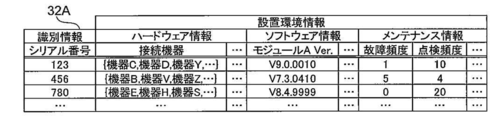
- the acquisition unit 30A acquires the transmitted identification information and installation environment information as described above, associates the acquired identification information and installation environment information, and stores them in the storage unit 32 as installation environment accumulation information 32A.
- FIG. 3 shows an example of the installation environment accumulation information 32A.
- a unique serial number assigned to each medical device 20 is applied as identification information.
- information about the hardware of the corresponding medical device 20 hereinafter referred to as “hardware information”
- information about the software of the corresponding medical device 20 hereinafter referred to as “software information”.
- maintenance information information related to maintenance of the corresponding medical device 20 is further included in the installation environment information.
- the hardware information includes model information indicating the model of the connected device to which the corresponding medical device 20 is connected.
- the hardware information includes, for example, hardware such as the model number of a CPU (Central Processing Unit) installed in the corresponding medical device 20 Further information on the configuration is included.
- CPU Central Processing Unit
- the software information includes the version of the software module A installed in the corresponding medical device 20.
- the software information includes, for example, information indicating the version and type of an OS (Operating System) installed in the corresponding medical device 20. Also included. Further, the software information further includes, for example, information related to the software configuration such as the version of the software module other than the software module A installed in the corresponding medical device 20.
- the maintenance information according to the present embodiment includes a failure frequency and an inspection frequency.
- the maintenance information includes, for example, maintenance such as the total period spent for the maintenance performed on the corresponding medical device 20. Further information is included.
- the failure frequency represents the number of times that a failure has occurred in the medical device 20 since the start of use of the corresponding medical device 20, but is not limited thereto.
- information regarding the frequency of failures such as an average value of occurrence intervals of failures may be used.
- the inspection frequency represents the number of times the medical device 20 has been inspected since the use of the corresponding medical device 20 is started.
- information regarding the frequency of inspection such as an interval between periodic inspections may be used.
- the classification unit 34 classifies the medical devices 20 into a plurality of groups (so-called clusters) based on the installation environment information acquired by the acquisition unit 30A. For this classification, for example, a clustering method such as the k-means method is applied. Specifically, for example, the classification unit 34 uses each item of the installation environment information of the installation environment accumulation information 32A as a feature quantity, and generates a feature vector having the same number of dimensions as the number of feature quantities.
- the maintenance staff may select a feature value used for generating a feature vector.
- the maintenance staff can determine from the log information of the medical device 20 in which the failure has occurred, that the failure is not caused by the software, a mode in which a plurality of items other than the software information are selected as feature amounts, etc. Is exemplified.
- the classification unit 34 classifies each medical device 20 into a plurality of groups by clustering using the generated feature vector.
- the group generated here represents a set of medical devices 20 having similar installation environments indicated by the installation environment information of items corresponding to the feature amounts used for generating the feature vectors. Note that a group obtained by clustering is also referred to as a cluster, but here it is collectively described as “group”.
- the specifying unit 36A is configured so that the medical device 20 in which a failure to be diagnosed has occurred (hereinafter referred to as “failure occurrence device 20”) is any group of the plurality of groups generated by the classification unit 34. Specify whether it belongs to. Specifically, the specifying unit 36A specifies a group to which the failure occurrence device 20 belongs (hereinafter referred to as “belonging group”) using the serial number of the failure occurrence device 20.
- the extraction unit 38 extracts items of installation environment information representing features different from other groups for the belonging group specified by the specification unit 36A. Specifically, the extraction unit 38 extracts a representative feature (hereinafter referred to as “representative feature”) that characterizes the belonging group in accordance with the extraction rule indicated by the extraction rule information 32B as the item of the installation environment information.
- the extraction rule according to the present embodiment calculates the difference between the average value of each feature amount of the belonging group and the corresponding feature amount other than the belonging group for each feature, and the absolute value of the calculated difference is the largest
- the rule is that the feature corresponding to the feature value is the representative feature of the group to which the group belongs. Therefore, the extraction unit 38 extracts the feature corresponding to the feature amount having the largest absolute value as the representative feature of the belonging group.
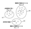
- FIG. 4 shows an example of a state in which a plurality of installation environment information classified by the classification unit 34 is mapped as a feature vector to one point on the common XY coordinate plane for each corresponding medical device 20.
- the points belonging to the same group are surrounded by a common circular line, and the representative features extracted by the extraction unit 38 are represented by corresponding circular shapes.
- the state marked close to the line is shown.
- each of the circles in FIG. 4 represents one medical device 20, and each star in FIG. 4 represents the failure occurrence device 20.
- FIG. 4 shows a state in which each medical device 20 is classified into three groups G1 to G3 by the classification unit 34 as an example.
- FIG. 4 shows a state in which the failure occurrence device 20 is specified as belonging to the group G3 by the specifying unit 36A as an example. Further, FIG. 4 shows a state in which “device X is connected” is extracted as a representative feature of the group G3 to which the failure occurrence device 20 belongs. Furthermore, in FIG. 4, the representative feature of the group G1 indicates that “the inspection frequency is high”, and the representative feature of the group G2 indicates that “the device B is connected”.
- the medical devices 20 corresponding to installation environment information having a relatively high feature vector similarity are classified into the same group.
- the display control unit 40A performs control to display the extraction result by the extraction unit 38 on the display unit. Specifically, as an example, the display control unit 40A uses the display information including the representative features extracted by the extraction unit 38 as a candidate for the cause of the failure in the failure occurrence device 20, and maintains the failure occurrence device 20. It is transmitted to the maintenance staff terminal 26 used by the maintenance staff.
- the “display” here includes not only visual display by a display device such as a display, but also audible display by a sound reproduction device such as a speaker, and permanent visual display by an image forming device such as a printer.
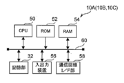
- the failure diagnosis apparatus 10A includes a CPU 50 that controls the overall operation of the failure diagnosis apparatus 10A, and a ROM (Read Only Memory) in which various programs and various parameters are stored in advance. 52. Further, the failure diagnosis apparatus 10A includes a RAM (Random Access Memory) 54 used as a work area when the CPU 50 executes various programs, and a nonvolatile storage unit 32 such as a flash memory.
- a RAM Random Access Memory
- the failure diagnosis apparatus 10A includes an input / output device 56 including a display device such as a display and an input device such as a mouse and a keyboard. Further, the failure diagnosis apparatus 10A includes a communication line I / F (Interface) unit 58 that is connected to the network 14 described above and performs transmission and reception of communication data with an external apparatus.
- I / F Interface
- the CPU 50, ROM 52, RAM 54, storage unit 32, input / output device 56, and communication line I / F unit 58 are connected to each other via a bus 60.
- the failure diagnosis apparatus 10A allows the CPU 50 to access the ROM 52, RAM 54, and storage unit 32, and to communicate with external devices via the communication line I / F unit 58. Send and receive data each. Further, the failure diagnosis apparatus 10 ⁇ / b> A causes the CPU 50 to acquire various instruction information via the input / output device 56 and display various information on the input / output device 56.
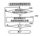
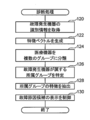
- FIG. 6 is a flowchart showing the processing flow of the installation environment information storage processing program executed by the CPU 50 when the power switch of the failure diagnosis apparatus 10A is turned on.
- the installation environment information storage processing program is installed in the ROM 52 in advance.
- FIG. 7 is a flowchart showing the flow of processing of the diagnostic processing program executed by the CPU 50 when the identification information of the failure occurrence device 20 and the diagnostic instruction for diagnosing the failure are received.
- the identification information and the diagnosis instruction are transmitted to the failure diagnosis apparatus 10A by operating the maintenance staff terminal 26 by a maintenance staff.
- the diagnostic processing program is installed in the ROM 52 in advance. Further, when the CPU 50 executes the installation environment information storage processing program and the diagnostic processing program, the CPU 50 functions as the acquisition unit 30A, the classification unit 34, the specification unit 36A, the extraction unit 38, and the display control unit 40A described above.
- each management device 22 periodically sends identification information (in this embodiment, a serial number) and installation environment information input in association with maintenance personnel to the failure diagnosis device 10A via the network 16. Send. Therefore, in step 100 of FIG. 6, the acquisition unit 30A waits for reception of identification information and installation environment information. When the acquisition unit 30A receives the identification information and the installation environment information, step 100 is affirmative and the process proceeds to step 102.
- step 102 the acquisition unit 30A associates the received identification information and installation environment information, and stores them in the storage unit 32 as installation environment accumulation information 32A (see also FIG. 3).
- the acquisition unit 30A updates the installation environment information of the record corresponding to the received identification information.
- the acquisition unit 30A determines whether or not a predetermined timing has arrived as the end timing of the installation environment information storage process.
- the acquisition unit 30A returns to step 100 when this determination is a negative determination, and ends the installation environment information accumulation process when the determination is affirmative.
- the timing at which the power switch of the failure diagnosis apparatus 10A is turned off is applied as the end timing.
- the present invention is not limited to this.
- other timings such as a timing when an instruction to end the installation environment information accumulation process is performed by a maintenance staff or the like may be applied.
- the acquisition unit 30A acquires the received identification information of the malfunctioning device 20.
- the classification unit 34 characterizes each item of the installation environment information of the installation environment accumulation information 32A using the installation environment accumulation information 32A stored in the storage unit 32 by the installation environment information accumulation process as described above. As a quantity, a feature vector having the same number of dimensions as the number of feature quantities is generated.
- the classification unit 34 classifies the medical devices 20 into a plurality of groups using the feature vector generated in step 122 as described above.
- the specifying unit 36 ⁇ / b> A specifies the group to which the failure occurrence device 20 belongs from among the plurality of groups generated in step 124 using the identification information acquired in step 120.
- the extraction unit 38 extracts the representative feature of the belonging group specified in step 126 as described above.
- the display control unit 40A transmits the display information including the representative feature extracted in step 128 to the maintenance staff terminal 26 as a candidate for the cause of the failure in the failure occurrence device 20. Then, the diagnosis process is terminated.
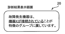
- FIG. 8 shows an example of the diagnosis result display screen. As shown in FIG. 8, on the diagnosis result display screen according to the present embodiment, the information indicating the representative feature is highlighted (indicated by an underline in the example shown in FIG. 8).
- the maintenance staff refers to the diagnosis result display screen to identify the cause of the failure in the failure occurrence device 20 and identify the cause of the failure in the failure occurrence device 20. For example, as illustrated in FIG. 8, when the representative feature of the failure occurrence device 20 is that it is connected to the device X, the maintenance staff indicates the state of the parts related to the connection of the failure occurrence device 20 to the device X. Check. Further, in this case, the maintenance staff confirms whether or not illegal data is included in the data transmitted from the device X to the failure occurrence device 20 by referring to the log information of the failure occurrence device 20 or the like. Thereby, it is possible to shorten the time spent for identifying the cause of the failure by the maintenance staff in the failure occurrence device 20.
- the diagnosis result display screen is not limited to the example shown in FIG.
- the display control unit 40A may transmit display information corresponding to the schematic diagram illustrated in FIG.
- the maintenance staff can know the classification result by clustering and which group the failure occurrence device 20 belongs to by referring to the diagnosis result display screen.
- the display control unit 40A may transmit display information corresponding to both the character string including the representative feature illustrated in FIG. 8 and the schematic diagram illustrated in FIG.
- the acquisition unit obtains a plurality of pieces of installation environment information including a plurality of items related to the installation environment in which each of a plurality of devices (medical devices 20) is installed. Acquired for each of the devices.
- the classification unit classifies the plurality of devices into a plurality of groups based on the installation environment information.
- the extraction unit sets the items of the installation environment information representing the characteristics different from those of other groups for the group to which the failure of the plurality of devices belongs. Extracting.
- the display control part (display control part 40A) performs control which displays the extraction result by an extraction part on a display part. As a result, it is possible to assist in identifying the cause of the failure in the device in which the failure has occurred.
- the installation environment information is obtained for each of a plurality of devices, classified into a plurality of groups, and the items of the installation environment information representing the characteristics of the group to which the failed device belongs are extracted. .
- the extracted items it is possible to notify the items of characteristic installation environment information in the equipment, and therefore support the identification work of the cause of the malfunction in the malfunctioning equipment. Can do.
- the first embodiment an example has been described in which processing for classifying the medical device 20 into a plurality of groups is performed when a failure diagnosis is performed.
- the second embodiment is different from the first embodiment in that the process of classifying the medical devices 20 into a plurality of groups is periodically performed in advance.
- connection configuration of the failure diagnosis apparatus 10B, the medical device 20, and the management apparatus 22 according to the present embodiment is the connection of the failure diagnosis apparatus 10A, the medical device 20, and the management apparatus 22 according to the first embodiment. Since it is the same as that of the configuration (see FIG. 1), description thereof is omitted here. Also, the main configuration of the electrical system of the failure diagnosis apparatus 10B according to the present embodiment is the same as the main configuration (see FIG. 5) of the electrical system of the failure diagnosis apparatus 10A according to the first embodiment. Therefore, the description here is omitted.
- the failure diagnosis apparatus 10 ⁇ / b> B further includes a reception unit 42.
- the accepting unit 42 accepts installation environment information of the malfunctioning device 20 when diagnosing a malfunction. Specifically, as an example, a maintenance person uses the maintenance person terminal 26 to transmit the installation environment information of the failure occurrence device 20 to the failure diagnosis apparatus 10B. Then, the reception unit 42 receives the installation environment information transmitted from the maintenance staff terminal 26. Note that the installation environment information of the failure occurrence device 20 may be directly input to the failure diagnosis apparatus 10B.
- the specifying unit 36B specifies the group to which the failure occurrence device 20 belongs based on the installation environment information received by the receiving unit 42. Specifically, similarly to the classification by clustering by the classification unit 34, the failure generating device 20 is assigned to one of a plurality of groups generated by the classification by the classification unit 34 based on the installation environment information of the failure generating device 20. Classify. That is, the specifying unit 36B specifies the group into which the failure occurrence device 20 is classified as the belonging group based on this classification.
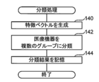
- FIG. 10 is a flowchart showing the flow of processing of the classification processing program executed by the CPU 50 every predetermined period.
- the classification processing program is installed in the ROM 52 in advance. Further, the classification processing program may be executed at each timing when the installation environment accumulation information 32A is updated, for example.
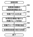
- FIG. 11 is a flowchart showing the flow of processing of the diagnostic processing program executed by the CPU 50 when the installation environment information of the failure occurrence device 20 and the diagnosis instruction for diagnosing the failure are received.
- the installation environment information and the diagnosis instruction are transmitted to the failure diagnosis apparatus 10 ⁇ / b> B by the operation of the maintenance staff terminal 26 by the maintenance staff when a failure occurs in the medical device 20, for example.
- the diagnostic processing program is installed in the ROM 52 in advance.
- the CPU 50 executes the installation environment information storage processing program, the classification processing program, and the diagnosis processing program, so that the CPU 50 acquires the above-described acquisition unit 30A, classification unit 34, identification unit 36B, extraction unit 38, display control unit 40A, And it functions as the reception unit 42.
- step 140 of FIG. 10 as in step 122, the classification unit 34 uses the installation environment storage information 32A stored in the storage unit 32 to change each item of the installation environment information of the installation environment storage information 32A to the feature amount.
- the feature vector is generated as follows.
- the classification unit 34 classifies the medical devices 20 into a plurality of groups using the feature vector generated in step 140.
- the classification unit 34 stores the classification result information indicating the classification result in step 142 in the storage unit 32, and then ends the classification process.
- step 160 of FIG. 11 the accepting unit 42 accepts the received installation environment information of the malfunctioning device 20.
- the specifying unit 36B generates a feature vector having the same number of dimensions as the number of feature amounts, using each item of the installation environment information received in step 160 as a feature amount.
- the specifying unit 36B uses the feature vector generated in step 162 and the classification result information stored in the storage unit 32 by the classification process, to which the failure occurrence device 20 belongs. Is identified.
- the extraction unit 38 extracts representative features of the belonging group specified in step 164.
- step 168 the display control unit 40A displays the display information including the representative feature extracted in step 166 as a candidate for the cause of the failure in the failure occurrence device 20, as the maintenance staff terminal 26. After the transmission, the diagnosis process is terminated.
- the belonging group identification process is performed based on the installation environment information of the failure occurrence device 20, and therefore the identification information may not be included in the installation environment accumulation information 32A. .
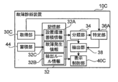
- connection configuration of the failure diagnosis apparatus 10C, the medical device 20, and the management device 22 according to the present embodiment is the connection of the failure diagnosis apparatus 10A, the medical device 20, and the management device 22 according to the first embodiment. Since it is the same as that of the configuration (see FIG. 1), description thereof is omitted here. Also, the main configuration of the electrical system of the failure diagnosis apparatus 10C according to the present embodiment is the same as the main configuration (see FIG. 5) of the electrical system of the failure diagnosis apparatus 10A according to the first embodiment. Therefore, the description here is omitted.
- the failure diagnosis apparatus 10C further includes a storage unit 44.
- the storage unit 44 receives failure information related to the type of failure that has occurred in the medical device 20 and identification information of the corresponding medical device 20.
- the failure information and the identification information are transmitted to the failure diagnosis apparatus 10 ⁇ / b> C by the operation of the maintenance staff terminal 26 by the maintenance staff when a failure occurs in the medical device 20, for example.
- the storage unit 44 associates the received identification information and failure information and stores them in the storage unit 32 as failure occurrence information 32C.
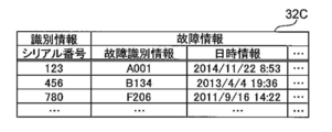
- FIG. 13 shows an example of the failure occurrence information 32C.
- the failure information includes failure identification information for identifying the type of failure and date / time information indicating the date and time when the failure occurred.
- the failure information includes, for example, a type of failure corresponding to the failure identification information in the past in the medical device 20 corresponding to the identification information. It also includes the cumulative number of times that was done.
- the acquisition unit 30C further acquires the identification information and the failure identification information of the failure occurrence device 20.
- the maintenance person specifies the failure identification information based on the log information of the failure occurrence device 20, etc., and uses the maintenance person terminal 26 to break down the identification information and failure identification information of the failure occurrence device 20. It transmits to the diagnostic apparatus 10C.
- the identification information and the failure identification information of the failure occurrence device 20 may be transmitted from the failure occurrence device 20 to the failure diagnosis device 10C via the network 16, or directly input to the failure diagnosis device 10C by a maintenance staff or the like. May be.
- the display control unit 40C has the same type as the failure type indicated by the failure identification information acquired by the acquisition unit 30C based on the failure occurrence information 32C stored by the storage unit 44. In a state where the generated medical device 20 can be identified, control is performed to display the group classified by the classification unit 34.
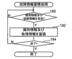
- FIG. 14 is a flowchart showing a flow of processing of a failure information storage processing program executed by the CPU 50 when the power switch of the failure diagnosis apparatus 10C is turned on.
- the failure information storage processing program is preinstalled in the ROM 52.
- FIG. 15 is a flowchart showing a flow of processing of the diagnostic processing program executed by the CPU 50 when the identification information and the failure identification information of the failure occurrence device 20 and the diagnosis instruction for diagnosing the failure are received. .
- the identification information, the failure identification information, and the diagnosis instruction for diagnosing the failure are transmitted to the failure diagnosis apparatus 10C by operating the maintenance staff terminal 26 by the maintenance staff when a failure occurs in the medical device 20, for example. Is done.
- the diagnostic processing program is installed in the ROM 52 in advance.
- the steps in FIG. 15 that execute the same processing as in FIG. 7 are denoted by the same step numbers as in FIG.
- the diagnostic process according to the present embodiment is different from the diagnostic process according to the first embodiment in that step 121 is executed instead of step 120.
- the diagnostic processing according to the present embodiment is different from the diagnostic processing according to the first embodiment in that steps 132 and 134 are executed instead of step 130.
- the CPU 50 executes the installation environment information storage processing program, the failure information storage processing program, and the diagnosis processing program, so that the CPU 50 obtains the acquisition unit 30C, the classification unit 34, the specification unit 36A, the extraction unit 38, and the display control unit described above. 40C and the storage unit 44 function.
- step 180 of FIG. 14 the storage unit 44 waits for reception of identification information and failure information.
- step 180 is affirmative and the process proceeds to step 182.
- step 182 the storage unit 44 associates the identification information and failure information received in step 180, and stores them in the storage unit 32 as failure occurrence information 32C (see also FIG. 13).
- step 184 the storage unit 44 determines whether or not a predetermined timing has arrived as the end timing of the failure information storage process. The accumulating unit 44 returns to Step 180 when this determination is negative, and ends this failure information accumulation process when it is affirmative.
- the timing at which the power switch of the failure diagnosis apparatus 10C is turned off is applied as the end timing, but the present invention is not limited to this.
- other timing such as a timing at which an instruction input for ending this failure information storage process is performed by a maintenance staff or the like may be applied.
- the acquisition unit 30C acquires the received identification information and failure identification information of the failure occurrence device 20. Thereafter, in step 132, the display control unit 40C refers to the failure occurrence information 32C accumulated by the failure information accumulation process, and the failure of the same type as the failure type indicated by the failure identification information acquired in step 121. Acquires identification information of the medical device 20 that has occurred in the past.
- the display control unit 40C maintains display information for displaying the plurality of groups generated in step 124 in a state where the medical device 20 indicated by the identification information acquired in step 132 can be identified. To the employee terminal 26. Further, at the time of this transmission, the display control unit 40C sets the display information as information indicating a state in which the failure occurrence device 20 corresponding to the identification information acquired in step 121 can be specified, and adds the display information to the display information in step 128. The extracted representative feature is further included. Then, the display control unit 40C ends the diagnosis process after transmitting the display information to the maintenance staff terminal 26.
- FIG. 16 shows an example of the diagnosis result display screen.
- a plurality of installation environment information targeted for classification by the classification unit 34 is displayed on a common XY coordinate plane for each corresponding medical device 20.
- a schematic diagram of a state in which each point is mapped as a feature vector is displayed.
- each of the circles in FIG. 16 represents one medical device 20, and each star in FIG. 16 represents the failure occurrence device 20.
- Such a display corresponds to an example of displaying the classification result in a state in which a device in which a failure has occurred can be identified.
- the method of displaying the classification result in a state where the device in which the failure has occurred can be identified is not limited to this, and any person having ordinary skill in the art who has seen the display can identify the device in which the failure has occurred. It may be displayed.
- a triangle mark in FIG. 16 represents a medical device 20 in which a failure of the same type as the failure type that has occurred in the failure occurrence device 20 has occurred in the past.
- Such a display corresponds to an example of displaying a plurality of groups in a state in which a device having a failure of the same type as the failure type indicated by the failure information acquired by the acquisition unit 30C can be identified.
- the method of displaying a plurality of groups in a state where a device having a failure of the same type as the failure type indicated by the failure information acquired by the acquisition unit 30C can be identified is not limited to this. Any display may be used as long as the contractor can determine a device in which a failure of the same type as the failure type indicated by the failure information acquired by the acquisition unit 30C can be identified.
- FIG. 16 illustrates a state in which each medical device 20 is classified into three groups by the classification unit 34 as an example.
- FIG. 16 shows, as an example, a state in which “device X is connected” is extracted as a representative feature of the group to which the failure occurrence device 20 belongs.
- the maintenance staff can identify the cause of the failure in the failure occurrence device 20 by referring to the diagnosis result display screen while knowing the cause of the failure in the failure occurrence device 20.
- the maintenance staff compares the medical device 20 in the same group as the failure occurrence device 20 with the same type of failure that occurred in the failure occurrence device 20 in the past. You can see that there are many. Accordingly, the maintenance staff knows that “being connected to the device X” is relatively likely to be the cause of the failure occurring in the failure occurrence device 20, and then causes the failure of the failure occurrence device 20. Specific work can be done.
- the present invention is not limited to this.
- the identification information and the installation environment information may be transmitted from each medical device 20 to the failure diagnosis apparatus 10A via the network 16, or may be directly input to the failure diagnosis apparatus 10A by a maintenance staff or the like. Good.
- the management device 22 is not necessarily provided in each facility 18.
- a case has been described in which only one representative feature is extracted as a candidate for the cause of failure in the failure occurrence device 20, but the present invention is not limited to this.
- a plurality of features may be extracted as candidates for the cause of failure in the failure occurrence device 20.
- the extraction unit 38 starts from the feature corresponding to the feature value having the largest absolute value of the difference between the average value of each feature value of the belonging group and the corresponding feature value other than the belonging group.
- a mode of extracting a plurality of features is exemplified.
- the rule that the feature corresponding to the feature value having the largest absolute value is used as the representative feature of the belonging group is used as the extraction rule indicated by the extraction rule information 32B.
- the extraction rule a mode in which a variance value of each feature amount of the belonging group is calculated for each feature, and a feature corresponding to the feature amount having the largest calculated variance value is used as a representative feature of the belonging group is applied. It is good.
- the extraction rule the ratio of the variance value of each feature quantity in all groups to the variance value of each feature quantity in the group to which the group belongs is calculated for each feature, and the feature quantity corresponding to the largest ratio of the calculated variance values is handled. It is also possible to apply a rule that a feature is a representative feature of the group to which the group belongs.
- a plurality of rules may be applied as extraction rules, and a plurality of representative characteristics of the belonging group may be extracted according to each of the plurality of rules.
- a plurality of rules are set as the extraction rules, and when performing a failure diagnosis, a maintenance person selects which of the plurality of rules is used to extract the representative feature. It is good also as a form.
- the medical device 20 is classified into a plurality of groups based on one type of feature vector.
- the present invention is not limited to this.
- the medical device 20 may be individually classified into a plurality of groups based on each of a plurality of types of feature vectors having different installation environment information items as feature amounts.
- a form in which representative features are extracted for each of a plurality of groups to which the failure occurrence device 20 belongs is exemplified.
- the k-means method is applied to the classification of the installation environment information by the classification unit 34 .
- the present invention is not limited to this.
- other non-hierarchical methods such as minimum average variance method and self-organizing map may be applied to classify installation environment information.
- Shortest distance method, longest distance method, group average method, center of gravity A cluster analysis method using a hierarchical method such as a method or a Ward method may be applied.
- the failure diagnosis apparatus transmits display information corresponding to the diagnosis result display screen to the maintenance staff terminal and displays the diagnosis result display screen on the display of the maintenance staff terminal. It is not limited to.
- the diagnosis result display screen may be displayed on the display of the input / output device of the failure diagnosis apparatus.
- a medical device is applied as a device to be diagnosed for a failure
- the present invention is not limited to this.
- Other devices such as an information processing device such as a computer, an image reading device, and an image forming device may be applied as the device to be diagnosed for failure.
- the mode in which various programs are stored (installed) in advance in the ROM 52 has been described.
- the various programs may be provided in a form recorded on a recording medium such as a CD-ROM (Compact Disk-Read Only Memory), a DVD-ROM (Digital Versatile Disk-Read Only Memory), a USB (Universal Serial Bus) memory, or the like.
- Various programs may be downloaded from an external device via a network.
- 10A, 10B, 10C Failure diagnosis device 20 Medical device (failure occurrence device) 26 Maintenance staff terminals 30A, 30C Acquisition unit 32 Storage unit 32A Installation environment accumulation information 32B Extraction rule information 32C Failure occurrence information 34 Classification unit 36A, 36B Identification unit 38 Extraction unit 40A, 40C Display control unit 42 Reception unit 44 Storage unit 50 CPU
Landscapes
- Engineering & Computer Science (AREA)
- Health & Medical Sciences (AREA)
- General Business, Economics & Management (AREA)
- Biomedical Technology (AREA)
- Business, Economics & Management (AREA)
- Epidemiology (AREA)
- General Health & Medical Sciences (AREA)
- Medical Informatics (AREA)
- Primary Health Care (AREA)
- Public Health (AREA)
- Automation & Control Theory (AREA)
- General Physics & Mathematics (AREA)
- Physics & Mathematics (AREA)
- Management, Administration, Business Operations System, And Electronic Commerce (AREA)
- Test And Diagnosis Of Digital Computers (AREA)
- Information Retrieval, Db Structures And Fs Structures Therefor (AREA)
- Testing And Monitoring For Control Systems (AREA)
- Measuring And Recording Apparatus For Diagnosis (AREA)
Priority Applications (2)
| Application Number | Priority Date | Filing Date | Title |
|---|---|---|---|
| JP2017541474A JP6356920B2 (ja) | 2015-09-24 | 2016-08-10 | 故障診断装置、故障診断方法、及び故障診断プログラム |
| US15/909,180 US10796796B2 (en) | 2015-09-24 | 2018-03-01 | Fault diagnosis apparatus, fault diagnosis method, and fault diagnosis program |
Applications Claiming Priority (2)
| Application Number | Priority Date | Filing Date | Title |
|---|---|---|---|
| JP2015-187381 | 2015-09-24 | ||
| JP2015187381 | 2015-09-24 |
Related Child Applications (1)
| Application Number | Title | Priority Date | Filing Date |
|---|---|---|---|
| US15/909,180 Continuation US10796796B2 (en) | 2015-09-24 | 2018-03-01 | Fault diagnosis apparatus, fault diagnosis method, and fault diagnosis program |
Publications (1)
| Publication Number | Publication Date |
|---|---|
| WO2017051631A1 true WO2017051631A1 (ja) | 2017-03-30 |
Family
ID=58385941
Family Applications (1)
| Application Number | Title | Priority Date | Filing Date |
|---|---|---|---|
| PCT/JP2016/073625 Ceased WO2017051631A1 (ja) | 2015-09-24 | 2016-08-10 | 故障診断装置、故障診断方法、及び故障診断プログラム |
Country Status (3)
| Country | Link |
|---|---|
| US (1) | US10796796B2 (OSRAM) |
| JP (2) | JP6356920B2 (OSRAM) |
| WO (1) | WO2017051631A1 (OSRAM) |
Cited By (3)
| Publication number | Priority date | Publication date | Assignee | Title |
|---|---|---|---|---|
| JP2019028931A (ja) * | 2017-08-03 | 2019-02-21 | 日立アプライアンス株式会社 | 異常検知方法および異常検知システム |
| WO2022062672A1 (zh) * | 2020-09-25 | 2022-03-31 | 深圳星标科技股份有限公司 | 传感器故障处理方法及相关装置 |
| CN118588264A (zh) * | 2024-06-07 | 2024-09-03 | 深圳微子医疗有限公司 | 一种基于云平台的医疗设备自动化管理系统及方法 |
Families Citing this family (8)
| Publication number | Priority date | Publication date | Assignee | Title |
|---|---|---|---|---|
| JP6819909B2 (ja) * | 2015-10-13 | 2021-01-27 | 日本電気株式会社 | 構造物異常検知システム、構造物異常検知方法及び記録した記録媒体 |
| EP3279756B1 (de) * | 2016-08-01 | 2019-07-10 | Siemens Aktiengesellschaft | Diagnoseeinrichtung und verfahren zur überwachung des betriebs einer technischen anlage |
| KR20200014005A (ko) | 2018-07-31 | 2020-02-10 | 삼성전자주식회사 | 전자 장치 및 전자 장치의 결함 진단 방법. |
| KR20210030680A (ko) | 2019-09-10 | 2021-03-18 | 삼성전자주식회사 | 디스플레이 장치 및 그 제어 방법 |
| CN110955226B (zh) * | 2019-11-22 | 2021-04-13 | 深圳市通用互联科技有限责任公司 | 设备故障预测方法、装置、计算机设备和存储介质 |
| KR102129480B1 (ko) * | 2020-04-23 | 2020-07-02 | 호서대학교 산학협력단 | 무인 자율주행차량의 예지보전장치 및 이의 예지보전방법 |
| CN113779247B (zh) * | 2021-08-27 | 2023-07-18 | 北京邮电大学 | 基于意图驱动的网络故障诊断方法及系统 |
| DE102022103586A1 (de) * | 2022-02-15 | 2023-08-17 | Olympus Winter & Ibe Gmbh | Verfahren zur Handhabung von Statusinformationen medizinischer Geräte, und System |
Citations (2)
| Publication number | Priority date | Publication date | Assignee | Title |
|---|---|---|---|---|
| JP2001306131A (ja) * | 2000-04-21 | 2001-11-02 | Toshiba Corp | タービン保守管理支援装置 |
| JP2009021348A (ja) * | 2007-07-11 | 2009-01-29 | Sharp Corp | 異常要因特定方法およびシステム、上記異常要因特定方法をコンピュータに実行させるためのプログラム、並びに上記プログラムを記録したコンピュータ読み取り可能な記録媒体 |
Family Cites Families (7)
| Publication number | Priority date | Publication date | Assignee | Title |
|---|---|---|---|---|
| JP5039739B2 (ja) | 2009-03-27 | 2012-10-03 | 東日本電信電話株式会社 | 故障位置確認装置及び故障位置確認方法 |
| JP5528125B2 (ja) * | 2010-01-08 | 2014-06-25 | キヤノン株式会社 | 管理装置、画像形成装置の管理方法、及び、プログラム |
| WO2012009804A1 (en) * | 2010-07-23 | 2012-01-26 | Corporation De L'ecole Polytechnique | Tool and method for fault detection of devices by condition based maintenance |
| JP5507527B2 (ja) * | 2011-11-11 | 2014-05-28 | シャープ株式会社 | 電力管理装置、電力管理装置の制御方法および制御プログラム |
| JP5530020B1 (ja) * | 2013-11-01 | 2014-06-25 | 株式会社日立パワーソリューションズ | 異常診断システム及び異常診断方法 |
| JP5530019B1 (ja) * | 2013-11-01 | 2014-06-25 | 株式会社日立パワーソリューションズ | 異常予兆検知システム及び異常予兆検知方法 |
| US10579460B2 (en) * | 2016-11-28 | 2020-03-03 | Electronics And Telecommunications Research Institute | Method and apparatus for diagnosing error of operating equipment in smart farm |
-
2016
- 2016-08-10 JP JP2017541474A patent/JP6356920B2/ja active Active
- 2016-08-10 WO PCT/JP2016/073625 patent/WO2017051631A1/ja not_active Ceased
-
2018
- 2018-03-01 US US15/909,180 patent/US10796796B2/en active Active
- 2018-06-13 JP JP2018112879A patent/JP6745840B2/ja active Active
Patent Citations (2)
| Publication number | Priority date | Publication date | Assignee | Title |
|---|---|---|---|---|
| JP2001306131A (ja) * | 2000-04-21 | 2001-11-02 | Toshiba Corp | タービン保守管理支援装置 |
| JP2009021348A (ja) * | 2007-07-11 | 2009-01-29 | Sharp Corp | 異常要因特定方法およびシステム、上記異常要因特定方法をコンピュータに実行させるためのプログラム、並びに上記プログラムを記録したコンピュータ読み取り可能な記録媒体 |
Cited By (3)
| Publication number | Priority date | Publication date | Assignee | Title |
|---|---|---|---|---|
| JP2019028931A (ja) * | 2017-08-03 | 2019-02-21 | 日立アプライアンス株式会社 | 異常検知方法および異常検知システム |
| WO2022062672A1 (zh) * | 2020-09-25 | 2022-03-31 | 深圳星标科技股份有限公司 | 传感器故障处理方法及相关装置 |
| CN118588264A (zh) * | 2024-06-07 | 2024-09-03 | 深圳微子医疗有限公司 | 一种基于云平台的医疗设备自动化管理系统及方法 |
Also Published As
| Publication number | Publication date |
|---|---|
| JP2018173970A (ja) | 2018-11-08 |
| US10796796B2 (en) | 2020-10-06 |
| US20180190378A1 (en) | 2018-07-05 |
| JPWO2017051631A1 (ja) | 2018-01-18 |
| JP6745840B2 (ja) | 2020-08-26 |
| JP6356920B2 (ja) | 2018-07-11 |
Similar Documents
| Publication | Publication Date | Title |
|---|---|---|
| JP6356920B2 (ja) | 故障診断装置、故障診断方法、及び故障診断プログラム | |
| EP3699708B1 (en) | Production facility monitoring device, production facility monitoring method, and production facility monitoring program | |
| US11782430B2 (en) | Abnormality diagnosis method, abnormality diagnosis device and non-transitory computer readable storage medium | |
| JP6919569B2 (ja) | ログ分析システム、方法、及び記録媒体 | |
| JP6441546B2 (ja) | コンピュータシステム、物体の診断方法及びプログラム | |
| JP2019070930A (ja) | 異常検知装置および異常検知方法 | |
| JP2019133212A (ja) | 異常検知システム、異常検知方法、および、プログラム | |
| WO2014145153A2 (en) | Automatic recording and graphing of measurement data | |
| JP6200833B2 (ja) | プラントと制御装置の診断装置 | |
| CN108629310B (zh) | 一种工程管理监督方法及装置 | |
| US20220091590A1 (en) | Failure sign detection system and failure sign detection method | |
| CN108763040B (zh) | 数据采集方法及数据采集装置 | |
| JP4443247B2 (ja) | 状態監視システムおよび状態監視方法 | |
| EP3211500B1 (en) | Monitoring system based on image analysis of photographs | |
| CN108804281A (zh) | 设施监视装置 | |
| JP6623453B2 (ja) | 障害原因特定装置、及びプログラム | |
| CN108875857A (zh) | 巡检方法、装置及系统 | |
| US11415958B2 (en) | Data extracting apparatus, data extracting method, and recording medium | |
| JP2014002430A (ja) | 設備点検システム及びその計測器 | |
| JP6898607B2 (ja) | 異常予兆検出システムおよび異常予兆検出方法 | |
| CN111784865A (zh) | 加氢站巡检数据处理方法及加氢站巡检装置 | |
| CN115496386A (zh) | 设备巡检方法、系统及计算机可读存储介质 | |
| JPWO2018198315A1 (ja) | コンピュータシステム、設備異常音判定方法及びプログラム | |
| JP6265767B2 (ja) | 通信診断装置、通信診断システム、通信診断方法、及びプログラム | |
| US20240185576A1 (en) | Image determination device, image determination method, and recording medium |
Legal Events
| Date | Code | Title | Description |
|---|---|---|---|
| 121 | Ep: the epo has been informed by wipo that ep was designated in this application |
Ref document number: 16848419 Country of ref document: EP Kind code of ref document: A1 |
|
| ENP | Entry into the national phase |
Ref document number: 2017541474 Country of ref document: JP Kind code of ref document: A |
|
| NENP | Non-entry into the national phase |
Ref country code: DE |
|
| 122 | Ep: pct application non-entry in european phase |
Ref document number: 16848419 Country of ref document: EP Kind code of ref document: A1 |