WO2017051631A1 - Fault diagnostic device, fault diagnostic method, and fault diagnostic program - Google Patents
Fault diagnostic device, fault diagnostic method, and fault diagnostic program Download PDFInfo
- Publication number
- WO2017051631A1 WO2017051631A1 PCT/JP2016/073625 JP2016073625W WO2017051631A1 WO 2017051631 A1 WO2017051631 A1 WO 2017051631A1 JP 2016073625 W JP2016073625 W JP 2016073625W WO 2017051631 A1 WO2017051631 A1 WO 2017051631A1
- Authority
- WO
- WIPO (PCT)
- Prior art keywords
- failure
- unit
- installation environment
- information
- display
- Prior art date
Links
Images


Classifications
-
- G—PHYSICS
- G16—INFORMATION AND COMMUNICATION TECHNOLOGY [ICT] SPECIALLY ADAPTED FOR SPECIFIC APPLICATION FIELDS
- G16H—HEALTHCARE INFORMATICS, i.e. INFORMATION AND COMMUNICATION TECHNOLOGY [ICT] SPECIALLY ADAPTED FOR THE HANDLING OR PROCESSING OF MEDICAL OR HEALTHCARE DATA
- G16H40/00—ICT specially adapted for the management or administration of healthcare resources or facilities; ICT specially adapted for the management or operation of medical equipment or devices
- G16H40/40—ICT specially adapted for the management or administration of healthcare resources or facilities; ICT specially adapted for the management or operation of medical equipment or devices for the management of medical equipment or devices, e.g. scheduling maintenance or upgrades
-
- G—PHYSICS
- G05—CONTROLLING; REGULATING
- G05B—CONTROL OR REGULATING SYSTEMS IN GENERAL; FUNCTIONAL ELEMENTS OF SUCH SYSTEMS; MONITORING OR TESTING ARRANGEMENTS FOR SUCH SYSTEMS OR ELEMENTS
- G05B23/00—Testing or monitoring of control systems or parts thereof
- G05B23/02—Electric testing or monitoring
-
- G—PHYSICS
- G05—CONTROLLING; REGULATING
- G05B—CONTROL OR REGULATING SYSTEMS IN GENERAL; FUNCTIONAL ELEMENTS OF SUCH SYSTEMS; MONITORING OR TESTING ARRANGEMENTS FOR SUCH SYSTEMS OR ELEMENTS
- G05B2219/00—Program-control systems
- G05B2219/30—Nc systems
- G05B2219/32—Operator till task planning
- G05B2219/32287—Medical, chemical, biological laboratory
-
- G—PHYSICS
- G05—CONTROLLING; REGULATING
- G05B—CONTROL OR REGULATING SYSTEMS IN GENERAL; FUNCTIONAL ELEMENTS OF SUCH SYSTEMS; MONITORING OR TESTING ARRANGEMENTS FOR SUCH SYSTEMS OR ELEMENTS
- G05B23/00—Testing or monitoring of control systems or parts thereof
- G05B23/02—Electric testing or monitoring
- G05B23/0205—Electric testing or monitoring by means of a monitoring system capable of detecting and responding to faults
- G05B23/0259—Electric testing or monitoring by means of a monitoring system capable of detecting and responding to faults characterized by the response to fault detection
- G05B23/0267—Fault communication, e.g. human machine interface [HMI]
Definitions
- the present invention relates to a failure diagnosis device, a failure diagnosis method, and a failure diagnosis program.
- Patent Document 1 discloses a failure location confirmation device that identifies the location of a failure that has occurred in a network.
- network devices are associated with customer information, and failure information is associated with a combination of network device states.
- this failure location confirmation apparatus receives the inquiry of a failure from a customer, the state of the network apparatus linked
- this failure location confirmation device it is possible to confirm failure information relating to a specific customer without examining the entire network by acquiring failure information associated with a combination of collected network device states. ing.
- Patent Document 2 discloses a detection system for detecting an abnormality sign of a mechanical facility.
- time-series data including sensor data is acquired as observation data from mechanical equipment, and normal data acquired in the past is clustered.
- a cluster having the smallest distance from the observation data is selected from the two or more clustered clusters, and an abnormality sign of the mechanical equipment is determined based on the distance between the selected cluster and the observation data. Is detected.
- the failure information to be acquired is limited to known information, and when sufficient failure information is not accumulated or an unknown failure occurs, a failure occurs. In many cases, it is not possible to extract the cause of the cause.
- Patent Document 2 detects a sign of equipment failure, and does not extract a cause of failure from a cluster obtained by clustering.
- the present invention has been made in view of the above circumstances, and provides a failure diagnosis device, a failure diagnosis method, and a failure diagnosis program capable of supporting the identification of the cause of failure in a device in which a failure has occurred. For the purpose.
- the failure diagnosis apparatus of the present invention includes an acquisition unit that acquires, for each of a plurality of devices, installation environment information including a plurality of items related to the installation environment in which each of the plurality of devices is installed. Based on the installation environment information, a classification unit that classifies a plurality of devices into a plurality of groups, and a group to which a device in which a failure occurs among a plurality of devices belongs, An extraction unit that extracts items and a display control unit that performs control to display an extraction result of the extraction unit on the display unit are provided.
- the classification unit may perform classification based on items that are candidates for the cause of the failure in the installation environment information.
- the display control unit may perform control to display the classification result by the classification unit on the display unit in a state where the classification result can be identified for each classified group.
- the display control unit may perform control to display the classification result on the display unit so that the device in which the failure has occurred can be identified.
- the failure diagnosis apparatus of the present invention further includes a storage unit that stores failure occurrence information in which failure information related to the type of failure that has occurred in the device and identification information assigned to each of the plurality of devices are associated with each other.
- the acquisition unit acquires failure information of the device in which the failure has occurred, and the display control unit, based on the failure occurrence information stored by the storage unit, the type of failure indicated by the failure information acquired by the acquisition unit You may perform control which displays a some group on a display part in the state which can identify the apparatus which the same kind of failure generate
- the installation environment information may include a plurality of items related to at least one of hardware related to the device to which the device is connected, software used in the device, and maintenance of the device. .
- the extraction unit may extract items of installation environment information representing each of a plurality of features in order from the feature having the highest degree of difference.
- the failure diagnosis apparatus of the present invention further includes a reception unit that receives input of installation environment information of a device in which a failure has occurred, and the classification unit uses the acquisition unit based on the installation environment information received by the reception unit.
- a device in which a failure has occurred may be classified into any of a plurality of groups classified based on the acquired installation environment information.
- the device may be a medical device.
- the failure diagnosis method of the present invention acquires installation environment information including a plurality of items related to the installation environment in which each of the plurality of devices is installed for each of the plurality of devices, and installs them. Based on the environment information, classify multiple devices into multiple groups, and extract the items of installation environment information that represent different features from other groups for the group to which the failed device belongs. The control is performed to display the extraction result on the display unit.
- the failure diagnosis program of the present invention is for causing a computer to function as an acquisition unit, a classification unit, an extraction unit, and a display control unit of the failure diagnosis apparatus of the present invention.
- a failure diagnosis apparatus 10A is provided in a facility 12, and is connected to a network 16 such as a WAN (Wide Area Network) via a network 14 such as a LAN (Local Area Network). It is connected.
- a network 16 such as a WAN (Wide Area Network)
- a network 14 such as a LAN (Local Area Network). It is connected.
- each of the facilities 18A to 18C a plurality of medical devices 20 to be diagnosed by the failure diagnosis device 10A and a management device 22 for managing the medical devices 20 are installed.
- the medical device 20 and the management device 22 are connected to each other via a network 24 such as a LAN, and the network 24 is connected to the network 16. Accordingly, the medical devices 20 of the facilities 18A to 18C and the failure diagnosis apparatus 10A of the facility 12 can communicate with each other via the network 16.
- FIG. 1 shows an example in which a mobile terminal 26 (hereinafter referred to as “maintenance worker terminal 26”) used by a maintenance worker who performs maintenance of the medical device 20 is brought into the facility 18A by the maintenance worker. ing.
- the maintenance staff terminal 26 includes a display device such as a display and an input device such as a keyboard.
- the maintenance staff terminal 26 can communicate with other devices via the network 24 and the network 16 by wireless communication.
- the failure diagnosis apparatus 10A is configured as a server, and includes an acquisition unit 30A, a storage unit 32, a classification unit 34, a specification unit 36A, an extraction unit 38, and a display control unit 40A as illustrated in FIG. I have.
- extraction rule information 32B which will be described later, is input in advance by a maintenance staff or the like and stored in the storage unit 32.
- the acquisition unit 30A medically stores identification information that uniquely identifies the medical device 20 provided in each facility 18 and installation environment information including a plurality of items regarding the installation environment in which the medical device 20 is installed. Obtained for each device 20. Specifically, as an example, the maintenance staff inputs the management device 22 in each facility 18 in association with the identification information and installation environment information of the corresponding medical device 20 in each facility 18. The identification information and the installation environment information are input for each medical device 20 regardless of whether the medical device 20 is operating normally.
- Each management device 22 periodically transmits the identification information and installation environment information input in association with the maintenance staff to the failure diagnosis device 10A via the network 16.
- the maintenance staff inputs the installation environment information to the management device 22 every time the installation environment indicated by the installation environment information is changed.
- the acquisition unit 30A acquires the transmitted identification information and installation environment information as described above, associates the acquired identification information and installation environment information, and stores them in the storage unit 32 as installation environment accumulation information 32A.
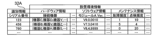
- FIG. 3 shows an example of the installation environment accumulation information 32A.
- a unique serial number assigned to each medical device 20 is applied as identification information.
- information about the hardware of the corresponding medical device 20 hereinafter referred to as “hardware information”
- information about the software of the corresponding medical device 20 hereinafter referred to as “software information”.
- maintenance information information related to maintenance of the corresponding medical device 20 is further included in the installation environment information.
- the hardware information includes model information indicating the model of the connected device to which the corresponding medical device 20 is connected.
- the hardware information includes, for example, hardware such as the model number of a CPU (Central Processing Unit) installed in the corresponding medical device 20 Further information on the configuration is included.
- CPU Central Processing Unit
- the software information includes the version of the software module A installed in the corresponding medical device 20.
- the software information includes, for example, information indicating the version and type of an OS (Operating System) installed in the corresponding medical device 20. Also included. Further, the software information further includes, for example, information related to the software configuration such as the version of the software module other than the software module A installed in the corresponding medical device 20.
- the maintenance information according to the present embodiment includes a failure frequency and an inspection frequency.
- the maintenance information includes, for example, maintenance such as the total period spent for the maintenance performed on the corresponding medical device 20. Further information is included.
- the failure frequency represents the number of times that a failure has occurred in the medical device 20 since the start of use of the corresponding medical device 20, but is not limited thereto.
- information regarding the frequency of failures such as an average value of occurrence intervals of failures may be used.
- the inspection frequency represents the number of times the medical device 20 has been inspected since the use of the corresponding medical device 20 is started.
- information regarding the frequency of inspection such as an interval between periodic inspections may be used.
- the classification unit 34 classifies the medical devices 20 into a plurality of groups (so-called clusters) based on the installation environment information acquired by the acquisition unit 30A. For this classification, for example, a clustering method such as the k-means method is applied. Specifically, for example, the classification unit 34 uses each item of the installation environment information of the installation environment accumulation information 32A as a feature quantity, and generates a feature vector having the same number of dimensions as the number of feature quantities.
- the maintenance staff may select a feature value used for generating a feature vector.
- the maintenance staff can determine from the log information of the medical device 20 in which the failure has occurred, that the failure is not caused by the software, a mode in which a plurality of items other than the software information are selected as feature amounts, etc. Is exemplified.
- the classification unit 34 classifies each medical device 20 into a plurality of groups by clustering using the generated feature vector.
- the group generated here represents a set of medical devices 20 having similar installation environments indicated by the installation environment information of items corresponding to the feature amounts used for generating the feature vectors. Note that a group obtained by clustering is also referred to as a cluster, but here it is collectively described as “group”.
- the specifying unit 36A is configured so that the medical device 20 in which a failure to be diagnosed has occurred (hereinafter referred to as “failure occurrence device 20”) is any group of the plurality of groups generated by the classification unit 34. Specify whether it belongs to. Specifically, the specifying unit 36A specifies a group to which the failure occurrence device 20 belongs (hereinafter referred to as “belonging group”) using the serial number of the failure occurrence device 20.
- the extraction unit 38 extracts items of installation environment information representing features different from other groups for the belonging group specified by the specification unit 36A. Specifically, the extraction unit 38 extracts a representative feature (hereinafter referred to as “representative feature”) that characterizes the belonging group in accordance with the extraction rule indicated by the extraction rule information 32B as the item of the installation environment information.
- the extraction rule according to the present embodiment calculates the difference between the average value of each feature amount of the belonging group and the corresponding feature amount other than the belonging group for each feature, and the absolute value of the calculated difference is the largest
- the rule is that the feature corresponding to the feature value is the representative feature of the group to which the group belongs. Therefore, the extraction unit 38 extracts the feature corresponding to the feature amount having the largest absolute value as the representative feature of the belonging group.
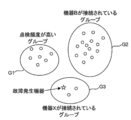
- FIG. 4 shows an example of a state in which a plurality of installation environment information classified by the classification unit 34 is mapped as a feature vector to one point on the common XY coordinate plane for each corresponding medical device 20.
- the points belonging to the same group are surrounded by a common circular line, and the representative features extracted by the extraction unit 38 are represented by corresponding circular shapes.
- the state marked close to the line is shown.
- each of the circles in FIG. 4 represents one medical device 20, and each star in FIG. 4 represents the failure occurrence device 20.
- FIG. 4 shows a state in which each medical device 20 is classified into three groups G1 to G3 by the classification unit 34 as an example.
- FIG. 4 shows a state in which the failure occurrence device 20 is specified as belonging to the group G3 by the specifying unit 36A as an example. Further, FIG. 4 shows a state in which “device X is connected” is extracted as a representative feature of the group G3 to which the failure occurrence device 20 belongs. Furthermore, in FIG. 4, the representative feature of the group G1 indicates that “the inspection frequency is high”, and the representative feature of the group G2 indicates that “the device B is connected”.
- the medical devices 20 corresponding to installation environment information having a relatively high feature vector similarity are classified into the same group.
- the display control unit 40A performs control to display the extraction result by the extraction unit 38 on the display unit. Specifically, as an example, the display control unit 40A uses the display information including the representative features extracted by the extraction unit 38 as a candidate for the cause of the failure in the failure occurrence device 20, and maintains the failure occurrence device 20. It is transmitted to the maintenance staff terminal 26 used by the maintenance staff.
- the “display” here includes not only visual display by a display device such as a display, but also audible display by a sound reproduction device such as a speaker, and permanent visual display by an image forming device such as a printer.
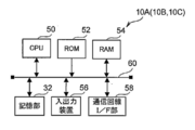
- the failure diagnosis apparatus 10A includes a CPU 50 that controls the overall operation of the failure diagnosis apparatus 10A, and a ROM (Read Only Memory) in which various programs and various parameters are stored in advance. 52. Further, the failure diagnosis apparatus 10A includes a RAM (Random Access Memory) 54 used as a work area when the CPU 50 executes various programs, and a nonvolatile storage unit 32 such as a flash memory.
- a RAM Random Access Memory
- the failure diagnosis apparatus 10A includes an input / output device 56 including a display device such as a display and an input device such as a mouse and a keyboard. Further, the failure diagnosis apparatus 10A includes a communication line I / F (Interface) unit 58 that is connected to the network 14 described above and performs transmission and reception of communication data with an external apparatus.
- I / F Interface
- the CPU 50, ROM 52, RAM 54, storage unit 32, input / output device 56, and communication line I / F unit 58 are connected to each other via a bus 60.
- the failure diagnosis apparatus 10A allows the CPU 50 to access the ROM 52, RAM 54, and storage unit 32, and to communicate with external devices via the communication line I / F unit 58. Send and receive data each. Further, the failure diagnosis apparatus 10 ⁇ / b> A causes the CPU 50 to acquire various instruction information via the input / output device 56 and display various information on the input / output device 56.
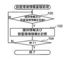
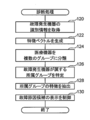
- FIG. 6 is a flowchart showing the processing flow of the installation environment information storage processing program executed by the CPU 50 when the power switch of the failure diagnosis apparatus 10A is turned on.
- the installation environment information storage processing program is installed in the ROM 52 in advance.
- FIG. 7 is a flowchart showing the flow of processing of the diagnostic processing program executed by the CPU 50 when the identification information of the failure occurrence device 20 and the diagnostic instruction for diagnosing the failure are received.
- the identification information and the diagnosis instruction are transmitted to the failure diagnosis apparatus 10A by operating the maintenance staff terminal 26 by a maintenance staff.
- the diagnostic processing program is installed in the ROM 52 in advance. Further, when the CPU 50 executes the installation environment information storage processing program and the diagnostic processing program, the CPU 50 functions as the acquisition unit 30A, the classification unit 34, the specification unit 36A, the extraction unit 38, and the display control unit 40A described above.
- each management device 22 periodically sends identification information (in this embodiment, a serial number) and installation environment information input in association with maintenance personnel to the failure diagnosis device 10A via the network 16. Send. Therefore, in step 100 of FIG. 6, the acquisition unit 30A waits for reception of identification information and installation environment information. When the acquisition unit 30A receives the identification information and the installation environment information, step 100 is affirmative and the process proceeds to step 102.
- step 102 the acquisition unit 30A associates the received identification information and installation environment information, and stores them in the storage unit 32 as installation environment accumulation information 32A (see also FIG. 3).
- the acquisition unit 30A updates the installation environment information of the record corresponding to the received identification information.
- the acquisition unit 30A determines whether or not a predetermined timing has arrived as the end timing of the installation environment information storage process.
- the acquisition unit 30A returns to step 100 when this determination is a negative determination, and ends the installation environment information accumulation process when the determination is affirmative.
- the timing at which the power switch of the failure diagnosis apparatus 10A is turned off is applied as the end timing.
- the present invention is not limited to this.
- other timings such as a timing when an instruction to end the installation environment information accumulation process is performed by a maintenance staff or the like may be applied.
- the acquisition unit 30A acquires the received identification information of the malfunctioning device 20.
- the classification unit 34 characterizes each item of the installation environment information of the installation environment accumulation information 32A using the installation environment accumulation information 32A stored in the storage unit 32 by the installation environment information accumulation process as described above. As a quantity, a feature vector having the same number of dimensions as the number of feature quantities is generated.
- the classification unit 34 classifies the medical devices 20 into a plurality of groups using the feature vector generated in step 122 as described above.
- the specifying unit 36 ⁇ / b> A specifies the group to which the failure occurrence device 20 belongs from among the plurality of groups generated in step 124 using the identification information acquired in step 120.
- the extraction unit 38 extracts the representative feature of the belonging group specified in step 126 as described above.
- the display control unit 40A transmits the display information including the representative feature extracted in step 128 to the maintenance staff terminal 26 as a candidate for the cause of the failure in the failure occurrence device 20. Then, the diagnosis process is terminated.
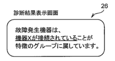
- FIG. 8 shows an example of the diagnosis result display screen. As shown in FIG. 8, on the diagnosis result display screen according to the present embodiment, the information indicating the representative feature is highlighted (indicated by an underline in the example shown in FIG. 8).
- the maintenance staff refers to the diagnosis result display screen to identify the cause of the failure in the failure occurrence device 20 and identify the cause of the failure in the failure occurrence device 20. For example, as illustrated in FIG. 8, when the representative feature of the failure occurrence device 20 is that it is connected to the device X, the maintenance staff indicates the state of the parts related to the connection of the failure occurrence device 20 to the device X. Check. Further, in this case, the maintenance staff confirms whether or not illegal data is included in the data transmitted from the device X to the failure occurrence device 20 by referring to the log information of the failure occurrence device 20 or the like. Thereby, it is possible to shorten the time spent for identifying the cause of the failure by the maintenance staff in the failure occurrence device 20.
- the diagnosis result display screen is not limited to the example shown in FIG.
- the display control unit 40A may transmit display information corresponding to the schematic diagram illustrated in FIG.
- the maintenance staff can know the classification result by clustering and which group the failure occurrence device 20 belongs to by referring to the diagnosis result display screen.
- the display control unit 40A may transmit display information corresponding to both the character string including the representative feature illustrated in FIG. 8 and the schematic diagram illustrated in FIG.
- the acquisition unit obtains a plurality of pieces of installation environment information including a plurality of items related to the installation environment in which each of a plurality of devices (medical devices 20) is installed. Acquired for each of the devices.
- the classification unit classifies the plurality of devices into a plurality of groups based on the installation environment information.
- the extraction unit sets the items of the installation environment information representing the characteristics different from those of other groups for the group to which the failure of the plurality of devices belongs. Extracting.
- the display control part (display control part 40A) performs control which displays the extraction result by an extraction part on a display part. As a result, it is possible to assist in identifying the cause of the failure in the device in which the failure has occurred.
- the installation environment information is obtained for each of a plurality of devices, classified into a plurality of groups, and the items of the installation environment information representing the characteristics of the group to which the failed device belongs are extracted. .
- the extracted items it is possible to notify the items of characteristic installation environment information in the equipment, and therefore support the identification work of the cause of the malfunction in the malfunctioning equipment. Can do.
- the first embodiment an example has been described in which processing for classifying the medical device 20 into a plurality of groups is performed when a failure diagnosis is performed.
- the second embodiment is different from the first embodiment in that the process of classifying the medical devices 20 into a plurality of groups is periodically performed in advance.
- connection configuration of the failure diagnosis apparatus 10B, the medical device 20, and the management apparatus 22 according to the present embodiment is the connection of the failure diagnosis apparatus 10A, the medical device 20, and the management apparatus 22 according to the first embodiment. Since it is the same as that of the configuration (see FIG. 1), description thereof is omitted here. Also, the main configuration of the electrical system of the failure diagnosis apparatus 10B according to the present embodiment is the same as the main configuration (see FIG. 5) of the electrical system of the failure diagnosis apparatus 10A according to the first embodiment. Therefore, the description here is omitted.
- the failure diagnosis apparatus 10 ⁇ / b> B further includes a reception unit 42.
- the accepting unit 42 accepts installation environment information of the malfunctioning device 20 when diagnosing a malfunction. Specifically, as an example, a maintenance person uses the maintenance person terminal 26 to transmit the installation environment information of the failure occurrence device 20 to the failure diagnosis apparatus 10B. Then, the reception unit 42 receives the installation environment information transmitted from the maintenance staff terminal 26. Note that the installation environment information of the failure occurrence device 20 may be directly input to the failure diagnosis apparatus 10B.
- the specifying unit 36B specifies the group to which the failure occurrence device 20 belongs based on the installation environment information received by the receiving unit 42. Specifically, similarly to the classification by clustering by the classification unit 34, the failure generating device 20 is assigned to one of a plurality of groups generated by the classification by the classification unit 34 based on the installation environment information of the failure generating device 20. Classify. That is, the specifying unit 36B specifies the group into which the failure occurrence device 20 is classified as the belonging group based on this classification.
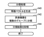
- FIG. 10 is a flowchart showing the flow of processing of the classification processing program executed by the CPU 50 every predetermined period.
- the classification processing program is installed in the ROM 52 in advance. Further, the classification processing program may be executed at each timing when the installation environment accumulation information 32A is updated, for example.
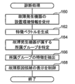
- FIG. 11 is a flowchart showing the flow of processing of the diagnostic processing program executed by the CPU 50 when the installation environment information of the failure occurrence device 20 and the diagnosis instruction for diagnosing the failure are received.
- the installation environment information and the diagnosis instruction are transmitted to the failure diagnosis apparatus 10 ⁇ / b> B by the operation of the maintenance staff terminal 26 by the maintenance staff when a failure occurs in the medical device 20, for example.
- the diagnostic processing program is installed in the ROM 52 in advance.
- the CPU 50 executes the installation environment information storage processing program, the classification processing program, and the diagnosis processing program, so that the CPU 50 acquires the above-described acquisition unit 30A, classification unit 34, identification unit 36B, extraction unit 38, display control unit 40A, And it functions as the reception unit 42.
- step 140 of FIG. 10 as in step 122, the classification unit 34 uses the installation environment storage information 32A stored in the storage unit 32 to change each item of the installation environment information of the installation environment storage information 32A to the feature amount.
- the feature vector is generated as follows.
- the classification unit 34 classifies the medical devices 20 into a plurality of groups using the feature vector generated in step 140.
- the classification unit 34 stores the classification result information indicating the classification result in step 142 in the storage unit 32, and then ends the classification process.
- step 160 of FIG. 11 the accepting unit 42 accepts the received installation environment information of the malfunctioning device 20.
- the specifying unit 36B generates a feature vector having the same number of dimensions as the number of feature amounts, using each item of the installation environment information received in step 160 as a feature amount.
- the specifying unit 36B uses the feature vector generated in step 162 and the classification result information stored in the storage unit 32 by the classification process, to which the failure occurrence device 20 belongs. Is identified.
- the extraction unit 38 extracts representative features of the belonging group specified in step 164.
- step 168 the display control unit 40A displays the display information including the representative feature extracted in step 166 as a candidate for the cause of the failure in the failure occurrence device 20, as the maintenance staff terminal 26. After the transmission, the diagnosis process is terminated.
- the belonging group identification process is performed based on the installation environment information of the failure occurrence device 20, and therefore the identification information may not be included in the installation environment accumulation information 32A. .
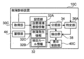
- connection configuration of the failure diagnosis apparatus 10C, the medical device 20, and the management device 22 according to the present embodiment is the connection of the failure diagnosis apparatus 10A, the medical device 20, and the management device 22 according to the first embodiment. Since it is the same as that of the configuration (see FIG. 1), description thereof is omitted here. Also, the main configuration of the electrical system of the failure diagnosis apparatus 10C according to the present embodiment is the same as the main configuration (see FIG. 5) of the electrical system of the failure diagnosis apparatus 10A according to the first embodiment. Therefore, the description here is omitted.
- the failure diagnosis apparatus 10C further includes a storage unit 44.
- the storage unit 44 receives failure information related to the type of failure that has occurred in the medical device 20 and identification information of the corresponding medical device 20.
- the failure information and the identification information are transmitted to the failure diagnosis apparatus 10 ⁇ / b> C by the operation of the maintenance staff terminal 26 by the maintenance staff when a failure occurs in the medical device 20, for example.
- the storage unit 44 associates the received identification information and failure information and stores them in the storage unit 32 as failure occurrence information 32C.
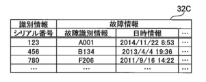
- FIG. 13 shows an example of the failure occurrence information 32C.
- the failure information includes failure identification information for identifying the type of failure and date / time information indicating the date and time when the failure occurred.
- the failure information includes, for example, a type of failure corresponding to the failure identification information in the past in the medical device 20 corresponding to the identification information. It also includes the cumulative number of times that was done.
- the acquisition unit 30C further acquires the identification information and the failure identification information of the failure occurrence device 20.
- the maintenance person specifies the failure identification information based on the log information of the failure occurrence device 20, etc., and uses the maintenance person terminal 26 to break down the identification information and failure identification information of the failure occurrence device 20. It transmits to the diagnostic apparatus 10C.
- the identification information and the failure identification information of the failure occurrence device 20 may be transmitted from the failure occurrence device 20 to the failure diagnosis device 10C via the network 16, or directly input to the failure diagnosis device 10C by a maintenance staff or the like. May be.
- the display control unit 40C has the same type as the failure type indicated by the failure identification information acquired by the acquisition unit 30C based on the failure occurrence information 32C stored by the storage unit 44. In a state where the generated medical device 20 can be identified, control is performed to display the group classified by the classification unit 34.
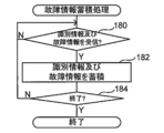
- FIG. 14 is a flowchart showing a flow of processing of a failure information storage processing program executed by the CPU 50 when the power switch of the failure diagnosis apparatus 10C is turned on.
- the failure information storage processing program is preinstalled in the ROM 52.
- FIG. 15 is a flowchart showing a flow of processing of the diagnostic processing program executed by the CPU 50 when the identification information and the failure identification information of the failure occurrence device 20 and the diagnosis instruction for diagnosing the failure are received. .
- the identification information, the failure identification information, and the diagnosis instruction for diagnosing the failure are transmitted to the failure diagnosis apparatus 10C by operating the maintenance staff terminal 26 by the maintenance staff when a failure occurs in the medical device 20, for example. Is done.
- the diagnostic processing program is installed in the ROM 52 in advance.
- the steps in FIG. 15 that execute the same processing as in FIG. 7 are denoted by the same step numbers as in FIG.
- the diagnostic process according to the present embodiment is different from the diagnostic process according to the first embodiment in that step 121 is executed instead of step 120.
- the diagnostic processing according to the present embodiment is different from the diagnostic processing according to the first embodiment in that steps 132 and 134 are executed instead of step 130.
- the CPU 50 executes the installation environment information storage processing program, the failure information storage processing program, and the diagnosis processing program, so that the CPU 50 obtains the acquisition unit 30C, the classification unit 34, the specification unit 36A, the extraction unit 38, and the display control unit described above. 40C and the storage unit 44 function.
- step 180 of FIG. 14 the storage unit 44 waits for reception of identification information and failure information.
- step 180 is affirmative and the process proceeds to step 182.
- step 182 the storage unit 44 associates the identification information and failure information received in step 180, and stores them in the storage unit 32 as failure occurrence information 32C (see also FIG. 13).
- step 184 the storage unit 44 determines whether or not a predetermined timing has arrived as the end timing of the failure information storage process. The accumulating unit 44 returns to Step 180 when this determination is negative, and ends this failure information accumulation process when it is affirmative.
- the timing at which the power switch of the failure diagnosis apparatus 10C is turned off is applied as the end timing, but the present invention is not limited to this.
- other timing such as a timing at which an instruction input for ending this failure information storage process is performed by a maintenance staff or the like may be applied.
- the acquisition unit 30C acquires the received identification information and failure identification information of the failure occurrence device 20. Thereafter, in step 132, the display control unit 40C refers to the failure occurrence information 32C accumulated by the failure information accumulation process, and the failure of the same type as the failure type indicated by the failure identification information acquired in step 121. Acquires identification information of the medical device 20 that has occurred in the past.
- the display control unit 40C maintains display information for displaying the plurality of groups generated in step 124 in a state where the medical device 20 indicated by the identification information acquired in step 132 can be identified. To the employee terminal 26. Further, at the time of this transmission, the display control unit 40C sets the display information as information indicating a state in which the failure occurrence device 20 corresponding to the identification information acquired in step 121 can be specified, and adds the display information to the display information in step 128. The extracted representative feature is further included. Then, the display control unit 40C ends the diagnosis process after transmitting the display information to the maintenance staff terminal 26.
- FIG. 16 shows an example of the diagnosis result display screen.
- a plurality of installation environment information targeted for classification by the classification unit 34 is displayed on a common XY coordinate plane for each corresponding medical device 20.
- a schematic diagram of a state in which each point is mapped as a feature vector is displayed.
- each of the circles in FIG. 16 represents one medical device 20, and each star in FIG. 16 represents the failure occurrence device 20.
- Such a display corresponds to an example of displaying the classification result in a state in which a device in which a failure has occurred can be identified.
- the method of displaying the classification result in a state where the device in which the failure has occurred can be identified is not limited to this, and any person having ordinary skill in the art who has seen the display can identify the device in which the failure has occurred. It may be displayed.
- a triangle mark in FIG. 16 represents a medical device 20 in which a failure of the same type as the failure type that has occurred in the failure occurrence device 20 has occurred in the past.
- Such a display corresponds to an example of displaying a plurality of groups in a state in which a device having a failure of the same type as the failure type indicated by the failure information acquired by the acquisition unit 30C can be identified.
- the method of displaying a plurality of groups in a state where a device having a failure of the same type as the failure type indicated by the failure information acquired by the acquisition unit 30C can be identified is not limited to this. Any display may be used as long as the contractor can determine a device in which a failure of the same type as the failure type indicated by the failure information acquired by the acquisition unit 30C can be identified.
- FIG. 16 illustrates a state in which each medical device 20 is classified into three groups by the classification unit 34 as an example.
- FIG. 16 shows, as an example, a state in which “device X is connected” is extracted as a representative feature of the group to which the failure occurrence device 20 belongs.
- the maintenance staff can identify the cause of the failure in the failure occurrence device 20 by referring to the diagnosis result display screen while knowing the cause of the failure in the failure occurrence device 20.
- the maintenance staff compares the medical device 20 in the same group as the failure occurrence device 20 with the same type of failure that occurred in the failure occurrence device 20 in the past. You can see that there are many. Accordingly, the maintenance staff knows that “being connected to the device X” is relatively likely to be the cause of the failure occurring in the failure occurrence device 20, and then causes the failure of the failure occurrence device 20. Specific work can be done.
- the present invention is not limited to this.
- the identification information and the installation environment information may be transmitted from each medical device 20 to the failure diagnosis apparatus 10A via the network 16, or may be directly input to the failure diagnosis apparatus 10A by a maintenance staff or the like. Good.
- the management device 22 is not necessarily provided in each facility 18.
- a case has been described in which only one representative feature is extracted as a candidate for the cause of failure in the failure occurrence device 20, but the present invention is not limited to this.
- a plurality of features may be extracted as candidates for the cause of failure in the failure occurrence device 20.
- the extraction unit 38 starts from the feature corresponding to the feature value having the largest absolute value of the difference between the average value of each feature value of the belonging group and the corresponding feature value other than the belonging group.
- a mode of extracting a plurality of features is exemplified.
- the rule that the feature corresponding to the feature value having the largest absolute value is used as the representative feature of the belonging group is used as the extraction rule indicated by the extraction rule information 32B.
- the extraction rule a mode in which a variance value of each feature amount of the belonging group is calculated for each feature, and a feature corresponding to the feature amount having the largest calculated variance value is used as a representative feature of the belonging group is applied. It is good.
- the extraction rule the ratio of the variance value of each feature quantity in all groups to the variance value of each feature quantity in the group to which the group belongs is calculated for each feature, and the feature quantity corresponding to the largest ratio of the calculated variance values is handled. It is also possible to apply a rule that a feature is a representative feature of the group to which the group belongs.
- a plurality of rules may be applied as extraction rules, and a plurality of representative characteristics of the belonging group may be extracted according to each of the plurality of rules.
- a plurality of rules are set as the extraction rules, and when performing a failure diagnosis, a maintenance person selects which of the plurality of rules is used to extract the representative feature. It is good also as a form.
- the medical device 20 is classified into a plurality of groups based on one type of feature vector.
- the present invention is not limited to this.
- the medical device 20 may be individually classified into a plurality of groups based on each of a plurality of types of feature vectors having different installation environment information items as feature amounts.
- a form in which representative features are extracted for each of a plurality of groups to which the failure occurrence device 20 belongs is exemplified.
- the k-means method is applied to the classification of the installation environment information by the classification unit 34 .
- the present invention is not limited to this.
- other non-hierarchical methods such as minimum average variance method and self-organizing map may be applied to classify installation environment information.
- Shortest distance method, longest distance method, group average method, center of gravity A cluster analysis method using a hierarchical method such as a method or a Ward method may be applied.
- the failure diagnosis apparatus transmits display information corresponding to the diagnosis result display screen to the maintenance staff terminal and displays the diagnosis result display screen on the display of the maintenance staff terminal. It is not limited to.
- the diagnosis result display screen may be displayed on the display of the input / output device of the failure diagnosis apparatus.
- a medical device is applied as a device to be diagnosed for a failure
- the present invention is not limited to this.
- Other devices such as an information processing device such as a computer, an image reading device, and an image forming device may be applied as the device to be diagnosed for failure.
- the mode in which various programs are stored (installed) in advance in the ROM 52 has been described.
- the various programs may be provided in a form recorded on a recording medium such as a CD-ROM (Compact Disk-Read Only Memory), a DVD-ROM (Digital Versatile Disk-Read Only Memory), a USB (Universal Serial Bus) memory, or the like.
- Various programs may be downloaded from an external device via a network.
- 10A, 10B, 10C Failure diagnosis device 20 Medical device (failure occurrence device) 26 Maintenance staff terminals 30A, 30C Acquisition unit 32 Storage unit 32A Installation environment accumulation information 32B Extraction rule information 32C Failure occurrence information 34 Classification unit 36A, 36B Identification unit 38 Extraction unit 40A, 40C Display control unit 42 Reception unit 44 Storage unit 50 CPU
Abstract
The purpose of the present invention is to obtain a fault diagnostic device, fault diagnostic method, and fault diagnostic program, which are capable of assisting with an operation of identifying a cause of a fault in a device in which the fault has occurred. Provided is a fault diagnostic device (10A) which: acquires, with an acquisition unit (32), for each of a plurality of medical devices, installation environment information which includes a plurality of items relating to the installation environments in which each of the plurality of medical devices has been installed; classifies, with a classification unit (34), the plurality of medical devices into a plurality of groups on the basis of the installation environment information; extracts, with an extraction unit (38), the installation environment information items which indicate characteristics which distinguish from other groups from the group to which the device whereupon a fault has occurred belongs, among the plurality of medical devices; and carries out, with a display control unit (40A), a control which causes a display unit to display the results of the extraction which is carried out by the extraction unit (38).
Description
本発明は、故障診断装置、故障診断方法、及び故障診断プログラムに関する。
The present invention relates to a failure diagnosis device, a failure diagnosis method, and a failure diagnosis program.
従来、電子機器等の機器における故障の原因の切り分けに関する技術や、故障の予兆を検知する技術が知られている。この種の技術として、特許文献1には、ネットワークで発生した故障の位置を切り分ける故障位置確認装置が開示されている。この故障位置確認装置では、顧客情報にネットワーク機器を関連付け、さらに、ネットワーク機器の状態の組み合わせに故障情報を対応付けておく。そして、この故障位置確認装置では、顧客から故障の問い合わせを受けた場合、顧客に関連付けられたネットワーク機器の状態を収集する。さらに、この故障位置確認装置では、収集したネットワーク機器の状態の組み合わせに対応付けた故障情報を取得することにより、ネットワーク全体を調べることなく、特定の顧客に関する故障情報を確認することが可能とされている。
Conventionally, there are known techniques for identifying the cause of a failure in a device such as an electronic device and a technology for detecting a sign of failure. As this type of technology, Patent Document 1 discloses a failure location confirmation device that identifies the location of a failure that has occurred in a network. In this failure location confirmation device, network devices are associated with customer information, and failure information is associated with a combination of network device states. And when this failure location confirmation apparatus receives the inquiry of a failure from a customer, the state of the network apparatus linked | related with the customer is collected. Furthermore, in this failure location confirmation device, it is possible to confirm failure information relating to a specific customer without examining the entire network by acquiring failure information associated with a combination of collected network device states. ing.
また、特許文献2には、機械設備の異常予兆を検知する検知システムが開示されている。この検知システムでは、機械設備からセンサデータを含む時系列データを観測データとして取得するとともに、過去に取得した正常データをクラスタリングする。また、この検知システムでは、クラスタリングした2以上のクラスタの中から、観測データとの距離が最小となるクラスタを選択し、選択したクラスタと観測データとの距離の大小に基づいて機械設備の異常予兆を検知する。
Further, Patent Document 2 discloses a detection system for detecting an abnormality sign of a mechanical facility. In this detection system, time-series data including sensor data is acquired as observation data from mechanical equipment, and normal data acquired in the past is clustered. In this detection system, a cluster having the smallest distance from the observation data is selected from the two or more clustered clusters, and an abnormality sign of the mechanical equipment is determined based on the distance between the selected cluster and the observation data. Is detected.
ところで、保守員が、故障が発生した機器に対処する場合、保守員による故障の原因の特定作業を支援するために、故障の原因の候補を保守員に報知することが好ましい。
By the way, when a maintenance person deals with a device in which a failure has occurred, it is preferable to notify the maintenance person of the cause of the failure in order to assist the maintenance person in identifying the cause of the failure.
しかしながら、特許文献1に記載の技術では、取得対象とする故障情報が既知の情報に限られており、十分な故障情報が蓄積されてない場合や、未知の故障が発生した場合には、故障の原因の候補を抽出することができない場合が多い。
However, in the technique described in Patent Document 1, the failure information to be acquired is limited to known information, and when sufficient failure information is not accumulated or an unknown failure occurs, a failure occurs. In many cases, it is not possible to extract the cause of the cause.
一方、特許文献2に記載の技術は、機器の故障の予兆を検知するものであり、クラスタリングにより得られたクラスタから、故障の原因の候補を抽出するものではない。
On the other hand, the technique described in Patent Document 2 detects a sign of equipment failure, and does not extract a cause of failure from a cluster obtained by clustering.
本発明は、以上の事情を鑑みて成されたものであり、故障が発生した機器における故障の原因の特定作業を支援することができる故障診断装置、故障診断方法、及び故障診断プログラムを提供することを目的とする。
The present invention has been made in view of the above circumstances, and provides a failure diagnosis device, a failure diagnosis method, and a failure diagnosis program capable of supporting the identification of the cause of failure in a device in which a failure has occurred. For the purpose.
上記目的を達成するために、本発明の故障診断装置は、複数の機器の各々が設置された設置環境に関する複数の項目を含む設置環境情報を複数の機器の各々毎に取得する取得部と、設置環境情報に基づいて、複数の機器を複数のグループに分類する分類部と、複数の機器のうちの故障が生じている機器が属するグループについて、他のグループと異なる特徴を表す設置環境情報の項目を抽出する抽出部と、抽出部による抽出結果を表示部に表示させる制御を行う表示制御部と、を備えている。
In order to achieve the above object, the failure diagnosis apparatus of the present invention includes an acquisition unit that acquires, for each of a plurality of devices, installation environment information including a plurality of items related to the installation environment in which each of the plurality of devices is installed. Based on the installation environment information, a classification unit that classifies a plurality of devices into a plurality of groups, and a group to which a device in which a failure occurs among a plurality of devices belongs, An extraction unit that extracts items and a display control unit that performs control to display an extraction result of the extraction unit on the display unit are provided.
なお、本発明の故障診断装置は、分類部が、設置環境情報における故障が生じている原因の候補となる項目に基づいて分類を行ってもよい。
In the failure diagnosis apparatus of the present invention, the classification unit may perform classification based on items that are candidates for the cause of the failure in the installation environment information.
また、本発明の故障診断装置は、表示制御部が、分類部による分類結果を、分類されたグループ毎に識別可能な状態で表示部に表示させる制御を行ってもよい。
In the failure diagnosis apparatus of the present invention, the display control unit may perform control to display the classification result by the classification unit on the display unit in a state where the classification result can be identified for each classified group.
特に、本発明の故障診断装置は、表示制御部が、故障が生じている機器を特定可能に、分類結果を表示部に表示させる制御を行ってもよい。
In particular, in the failure diagnosis apparatus of the present invention, the display control unit may perform control to display the classification result on the display unit so that the device in which the failure has occurred can be identified.
また、本発明の故障診断装置は、機器で発生した故障の種類に関する故障情報と複数の機器の各々に付与された識別情報とが対応付けられた故障発生情報を蓄積する蓄積部をさらに備え、取得部が、故障が生じている機器の故障情報を取得し、表示制御部が、蓄積部により蓄積された故障発生情報に基づいて、取得部により取得された故障情報によって示される故障の種類と同一の種類の故障が発生した機器を判別可能な状態で、複数のグループを表示部に表示させる制御を行ってもよい。
The failure diagnosis apparatus of the present invention further includes a storage unit that stores failure occurrence information in which failure information related to the type of failure that has occurred in the device and identification information assigned to each of the plurality of devices are associated with each other. The acquisition unit acquires failure information of the device in which the failure has occurred, and the display control unit, based on the failure occurrence information stored by the storage unit, the type of failure indicated by the failure information acquired by the acquisition unit You may perform control which displays a some group on a display part in the state which can identify the apparatus which the same kind of failure generate | occur | produced.
また、本発明の故障診断装置は、設置環境情報が、機器が接続される機器のハードウェア、機器で使用されるソフトウェア、及び機器のメンテナンスに関する情報の少なくとも1つに関する複数の項目を含んでもよい。
In the failure diagnosis apparatus of the present invention, the installation environment information may include a plurality of items related to at least one of hardware related to the device to which the device is connected, software used in the device, and maintenance of the device. .
また、本発明の故障診断装置は、抽出部が、異なる特徴を、最も異なる度合が高い特徴から順に、複数の特徴の各々を表す設置環境情報の項目を抽出してもよい。
Also, in the failure diagnosis apparatus of the present invention, the extraction unit may extract items of installation environment information representing each of a plurality of features in order from the feature having the highest degree of difference.
また、本発明の故障診断装置は、故障が生じている機器の設置環境情報の入力を受け付ける受付部をさらに備え、分類部が、受付部により受け付けられた設置環境情報に基づいて、取得部により取得された設置環境情報に基づいて分類した複数のグループの何れかに故障が生じている機器を分類してもよい。
In addition, the failure diagnosis apparatus of the present invention further includes a reception unit that receives input of installation environment information of a device in which a failure has occurred, and the classification unit uses the acquisition unit based on the installation environment information received by the reception unit. A device in which a failure has occurred may be classified into any of a plurality of groups classified based on the acquired installation environment information.
本発明の故障診断装置は、機器が、医療機器であってもよい。
In the failure diagnosis apparatus of the present invention, the device may be a medical device.
一方、上記目的を達成するために、本発明の故障診断方法は、複数の機器の各々が設置された設置環境に関する複数の項目を含む設置環境情報を複数の機器の各々毎に取得し、設置環境情報に基づいて、複数の機器を複数のグループに分類し、複数の機器のうちの故障が生じている機器が属するグループについて、他のグループと異なる特徴を表す設置環境情報の項目を抽出し、抽出結果を表示部に表示させる制御を行うものである。
On the other hand, in order to achieve the above object, the failure diagnosis method of the present invention acquires installation environment information including a plurality of items related to the installation environment in which each of the plurality of devices is installed for each of the plurality of devices, and installs them. Based on the environment information, classify multiple devices into multiple groups, and extract the items of installation environment information that represent different features from other groups for the group to which the failed device belongs. The control is performed to display the extraction result on the display unit.
さらに、上記目的を達成するために、本発明の故障診断プログラムは、コンピュータを、本発明の故障診断装置の取得部、分類部、抽出部、及び表示制御部として機能させるためのものである。
Furthermore, in order to achieve the above object, the failure diagnosis program of the present invention is for causing a computer to function as an acquisition unit, a classification unit, an extraction unit, and a display control unit of the failure diagnosis apparatus of the present invention.
本発明によれば、故障が発生した機器における故障の原因の特定作業を支援することができる。
According to the present invention, it is possible to support the identification work of the cause of the failure in the device in which the failure has occurred.
以下、図面を参照して、本発明を実施するための形態例を詳細に説明する。なお、ここでは、故障の診断対象とする電子機器として、医療機器を適用した形態例について説明する。
Hereinafter, exemplary embodiments for carrying out the present invention will be described in detail with reference to the drawings. Here, an example in which a medical device is applied as an electronic device to be diagnosed for a failure will be described.
[第1の実施の形態]
まず、図1を参照して、本実施の形態に係る故障診断装置10A、医療機器20、及び管理装置22の接続構成を説明する。図1に示すように、本実施の形態に係る故障診断装置10Aは、施設12に設けられ、LAN(Local Area Network)等のネットワーク14を介して、WAN(Wide Area Network)等のネットワーク16に接続されている。 [First Embodiment]
First, the connection configuration of thefailure diagnosis apparatus 10A, the medical device 20, and the management apparatus 22 according to the present embodiment will be described with reference to FIG. As shown in FIG. 1, a failure diagnosis apparatus 10A according to the present embodiment is provided in a facility 12, and is connected to a network 16 such as a WAN (Wide Area Network) via a network 14 such as a LAN (Local Area Network). It is connected.
まず、図1を参照して、本実施の形態に係る故障診断装置10A、医療機器20、及び管理装置22の接続構成を説明する。図1に示すように、本実施の形態に係る故障診断装置10Aは、施設12に設けられ、LAN(Local Area Network)等のネットワーク14を介して、WAN(Wide Area Network)等のネットワーク16に接続されている。 [First Embodiment]
First, the connection configuration of the
また、施設18A~18Cの各々には、故障診断装置10Aによる診断対象とする複数の医療機器20及び医療機器20を管理する管理装置22が設置されている。また、医療機器20及び管理装置22は、各々LAN等のネットワーク24を介して互いに接続されており、ネットワーク24はネットワーク16に接続されている。従って、施設18A~18Cの医療機器20と、施設12の故障診断装置10Aとは、ネットワーク16を介して互いに通信可能とされている。
Further, in each of the facilities 18A to 18C, a plurality of medical devices 20 to be diagnosed by the failure diagnosis device 10A and a management device 22 for managing the medical devices 20 are installed. The medical device 20 and the management device 22 are connected to each other via a network 24 such as a LAN, and the network 24 is connected to the network 16. Accordingly, the medical devices 20 of the facilities 18A to 18C and the failure diagnosis apparatus 10A of the facility 12 can communicate with each other via the network 16.
なお、以下では、施設18A~18Cを区別せずに総称する場合は、符号の末尾のアルファベットの符号を省略して説明する。また、各施設18内の医療機器20は、機器の設計仕様や使用状況等によりネットワーク24を介さずに、互いに電気的に直接接続されている機器を含む。また、図1では、医療機器20の保守を行う保守員が使用するモバイル端末26(以下、「保守員端末26」という。)が、保守員により施設18Aに持ち込まれた状態が一例として示されている。また、保守員端末26には、ディスプレイ等の表示装置、及びキーボード等の入力装置が備えられている。また、保守員端末26は、無線通信により、ネットワーク24及びネットワーク16を介した他の装置との通信が可能とされている。
In the following description, when the facilities 18A to 18C are collectively referred to without being distinguished, the alphabetical code at the end of the code is omitted. In addition, the medical devices 20 in each facility 18 include devices that are electrically connected directly to each other without using the network 24 depending on the design specifications and use conditions of the devices. FIG. 1 shows an example in which a mobile terminal 26 (hereinafter referred to as “maintenance worker terminal 26”) used by a maintenance worker who performs maintenance of the medical device 20 is brought into the facility 18A by the maintenance worker. ing. The maintenance staff terminal 26 includes a display device such as a display and an input device such as a keyboard. In addition, the maintenance staff terminal 26 can communicate with other devices via the network 24 and the network 16 by wireless communication.
次に、図2を参照して、故障診断装置10Aの機能的な構成について説明する。本実施の形態に係る故障診断装置10Aは、サーバとして構成され、図2に示すように、取得部30A、記憶部32、分類部34、特定部36A、抽出部38、及び表示制御部40Aを備えている。なお、本実施の形態では、後述する抽出ルール情報32Bが保守員等により予め入力され、記憶部32に記憶されている。
Next, a functional configuration of the failure diagnosis apparatus 10A will be described with reference to FIG. The failure diagnosis apparatus 10A according to the present embodiment is configured as a server, and includes an acquisition unit 30A, a storage unit 32, a classification unit 34, a specification unit 36A, an extraction unit 38, and a display control unit 40A as illustrated in FIG. I have. In the present embodiment, extraction rule information 32B, which will be described later, is input in advance by a maintenance staff or the like and stored in the storage unit 32.
本実施の形態に係る取得部30Aは、各施設18に設けられた医療機器20を一意に識別する識別情報、及び医療機器20が設置された設置環境に関する複数の項目を含む設置環境情報を医療機器20の各々毎に取得する。具体的には、一例として、保守員が各施設18内の管理装置22に対し、対応する各施設18内の医療機器20の識別情報及び設置環境情報を対応付けて入力する。なお、識別情報及び設置環境情報は、医療機器20が正常に稼働しているか否かとは無関係に、各医療機器20について入力される。
The acquisition unit 30A according to the present embodiment medically stores identification information that uniquely identifies the medical device 20 provided in each facility 18 and installation environment information including a plurality of items regarding the installation environment in which the medical device 20 is installed. Obtained for each device 20. Specifically, as an example, the maintenance staff inputs the management device 22 in each facility 18 in association with the identification information and installation environment information of the corresponding medical device 20 in each facility 18. The identification information and the installation environment information are input for each medical device 20 regardless of whether the medical device 20 is operating normally.
そして、各管理装置22は保守員により対応付けて入力された識別情報及び設置環境情報を、ネットワーク16を介して定期的に故障診断装置10Aに送信する。なお、保守員は、設置環境情報により示される設置環境が変更される度に、設置環境情報を管理装置22に入力する。
Each management device 22 periodically transmits the identification information and installation environment information input in association with the maintenance staff to the failure diagnosis device 10A via the network 16. The maintenance staff inputs the installation environment information to the management device 22 every time the installation environment indicated by the installation environment information is changed.
取得部30Aは、以上説明したように送信された識別情報及び設置環境情報を取得して、取得した識別情報及び設置環境情報を対応付けて、設置環境蓄積情報32Aとして記憶部32に記憶する。図3には、設置環境蓄積情報32Aの一例が示されている。
The acquisition unit 30A acquires the transmitted identification information and installation environment information as described above, associates the acquired identification information and installation environment information, and stores them in the storage unit 32 as installation environment accumulation information 32A. FIG. 3 shows an example of the installation environment accumulation information 32A.
図3に示すように、本実施の形態では、識別情報として、各医療機器20に割り当てられている固有のシリアル番号を適用している。また、本実施の形態では、対応する医療機器20のハードウェアに関する情報(以下、「ハードウェア情報」という。)、及び対応する医療機器20のソフトウェアに関する情報(以下、「ソフトウェア情報」という。)が設置環境情報に含まれる。また、本実施の形態では、対応する医療機器20のメンテナンスに関する情報(以下、「メンテナンス情報」という。)が設置環境情報にさらに含まれる。
As shown in FIG. 3, in this embodiment, a unique serial number assigned to each medical device 20 is applied as identification information. In the present embodiment, information about the hardware of the corresponding medical device 20 (hereinafter referred to as “hardware information”) and information about the software of the corresponding medical device 20 (hereinafter referred to as “software information”). Is included in the installation environment information. In the present embodiment, information related to maintenance of the corresponding medical device 20 (hereinafter referred to as “maintenance information”) is further included in the installation environment information.
図3に示すように、本実施の形態に係るハードウェア情報には、対応する医療機器20が接続されている接続機器の機種を示す機種情報が含まれる。なお、錯綜を回避するために、図3では図示を省略しているが、ハードウェア情報には、例えば、対応する医療機器20に搭載されているCPU(Central Processing Unit)の型番等のハードウェア構成に関する情報等がさらに含まれる。
As shown in FIG. 3, the hardware information according to the present embodiment includes model information indicating the model of the connected device to which the corresponding medical device 20 is connected. Although not shown in FIG. 3 in order to avoid complications, the hardware information includes, for example, hardware such as the model number of a CPU (Central Processing Unit) installed in the corresponding medical device 20 Further information on the configuration is included.
また、本実施の形態に係るソフトウェア情報には、対応する医療機器20にインストールされているソフトウェアモジュールAのバージョンが含まれる。なお、錯綜を回避するために、図3では図示を省略しているが、ソフトウェア情報には、例えば、対応する医療機器20にインストールされているOS(Operating System)のバージョン及び種類を示す情報がさらに含まれる。また、ソフトウェア情報には、例えば、対応する医療機器20にインストールされているソフトウェアモジュールA以外のソフトウェアモジュールのバージョン等のソフトウェア構成に関する情報がさらに含まれる。
In addition, the software information according to the present embodiment includes the version of the software module A installed in the corresponding medical device 20. Although not shown in FIG. 3 in order to avoid complications, the software information includes, for example, information indicating the version and type of an OS (Operating System) installed in the corresponding medical device 20. Also included. Further, the software information further includes, for example, information related to the software configuration such as the version of the software module other than the software module A installed in the corresponding medical device 20.
また、本実施の形態に係るメンテナンス情報には、故障頻度及び点検頻度が含まれる。なお、錯綜を回避するために、図3では図示を省略しているが、メンテナンス情報には、例えば、対応する医療機器20に対して行われたメンテナンスに費やされた総期間等のメンテナンスに関する情報がさらに含まれる。
In addition, the maintenance information according to the present embodiment includes a failure frequency and an inspection frequency. Although not shown in FIG. 3 in order to avoid complications, the maintenance information includes, for example, maintenance such as the total period spent for the maintenance performed on the corresponding medical device 20. Further information is included.
また、故障頻度とは、本実施の形態では、対応する医療機器20の使用を開始してからの、該医療機器20に故障が発生した回数を表すものとしているが、これに限定されず、例えば故障の発生間隔の平均値等、故障の頻度に関する情報であればよい。
In addition, in the present embodiment, the failure frequency represents the number of times that a failure has occurred in the medical device 20 since the start of use of the corresponding medical device 20, but is not limited thereto. For example, information regarding the frequency of failures such as an average value of occurrence intervals of failures may be used.
また、点検頻度とは、本実施の形態では、対応する医療機器20の使用を開始してからの、該医療機器20に対して点検が行われた回数を表すものとしているが、これに限定されず、例えば定期点検の間隔等、点検の頻度に関する情報であればよい。
In the present embodiment, the inspection frequency represents the number of times the medical device 20 has been inspected since the use of the corresponding medical device 20 is started. For example, information regarding the frequency of inspection such as an interval between periodic inspections may be used.
以下では、錯綜を回避するために、設置環境情報として、ハードウェア情報に含まれる接続機器と、ソフトウェア情報に含まれるソフトウェアモジュールAのバージョンと、メンテナンス情報に含まれる故障頻度及び点検頻度と、の4つの項目を適用した場合について説明する。また、以下では、一例として、上記4つの項目を医療機器20に生じる故障の原因の候補とした場合について説明する。
In the following, in order to avoid complications, as the installation environment information, the connected device included in the hardware information, the version of the software module A included in the software information, the failure frequency and the inspection frequency included in the maintenance information, A case where four items are applied will be described. Hereinafter, as an example, a case where the above four items are candidates for a cause of a failure occurring in the medical device 20 will be described.
本実施の形態に係る分類部34は、取得部30Aにより取得された設置環境情報に基づいて、各医療機器20を複数のグループ(所謂クラスタ)に分類する。この分類には、例えば、k-means法等のクラスタリングの手法を適用する。具体的には、例えば、分類部34は、設置環境蓄積情報32Aの設置環境情報の各項目を特徴量として、特徴量の数と同一の数の次元数の特徴ベクトルを生成する。
The classification unit 34 according to the present embodiment classifies the medical devices 20 into a plurality of groups (so-called clusters) based on the installation environment information acquired by the acquisition unit 30A. For this classification, for example, a clustering method such as the k-means method is applied. Specifically, for example, the classification unit 34 uses each item of the installation environment information of the installation environment accumulation information 32A as a feature quantity, and generates a feature vector having the same number of dimensions as the number of feature quantities.
なお、本実施の形態では、故障の原因の候補とする上記4つの項目に対応する特徴量を特徴ベクトルの生成に用いる特徴量として用いる場合について説明するが、これに限定されない。例えば、故障の診断を行う度に保守員が、特徴ベクトルの生成に用いる特徴量を選択してもよい。この場合、例えば、保守員は、故障が発生した医療機器20のログ情報等から、ソフトウェアに起因する故障ではないと判断できる場合は、ソフトウェア情報以外の複数の項目を特徴量として選択する形態等が例示される。
In the present embodiment, a case will be described in which feature amounts corresponding to the above four items that are candidates for the cause of failure are used as feature amounts used for generating feature vectors, but the present invention is not limited to this. For example, every time a failure is diagnosed, the maintenance staff may select a feature value used for generating a feature vector. In this case, for example, when the maintenance staff can determine from the log information of the medical device 20 in which the failure has occurred, that the failure is not caused by the software, a mode in which a plurality of items other than the software information are selected as feature amounts, etc. Is exemplified.
そして、分類部34は、生成した特徴ベクトルを用いて、クラスタリングにより、各医療機器20を複数のグループに分類する。ここで生成されるグループは、特徴ベクトルの生成に用いた特徴量に対応する項目の設置環境情報により示される設置環境が類似している医療機器20の集合を表す。なお、クラスタリングにより得られたグループは、クラスタとも呼ばれるが、ここでは「グループ」と統一して記載する。
Then, the classification unit 34 classifies each medical device 20 into a plurality of groups by clustering using the generated feature vector. The group generated here represents a set of medical devices 20 having similar installation environments indicated by the installation environment information of items corresponding to the feature amounts used for generating the feature vectors. Note that a group obtained by clustering is also referred to as a cluster, but here it is collectively described as “group”.
本実施の形態に係る特定部36Aは、診断対象とする故障が発生した医療機器20(以下、「故障発生機器20」という。)が、分類部34により生成された複数のグループの何れのグループに属するかを特定する。具体的には、特定部36Aは、故障発生機器20のシリアル番号を用いて、故障発生機器20が属するグループ(以下、「所属グループ」という。)を特定する。
The specifying unit 36A according to the present embodiment is configured so that the medical device 20 in which a failure to be diagnosed has occurred (hereinafter referred to as “failure occurrence device 20”) is any group of the plurality of groups generated by the classification unit 34. Specify whether it belongs to. Specifically, the specifying unit 36A specifies a group to which the failure occurrence device 20 belongs (hereinafter referred to as “belonging group”) using the serial number of the failure occurrence device 20.
本実施の形態に係る抽出部38は、特定部36Aにより特定された所属グループについて、他のグループと異なる特徴を表す設置環境情報の項目を抽出する。具体的には、抽出部38は、この設置環境情報の項目として、抽出ルール情報32Bにより示される抽出ルールに従って所属グループを特徴付ける代表的な特徴(以下、「代表特徴」という。)を抽出する。
The extraction unit 38 according to the present embodiment extracts items of installation environment information representing features different from other groups for the belonging group specified by the specification unit 36A. Specifically, the extraction unit 38 extracts a representative feature (hereinafter referred to as “representative feature”) that characterizes the belonging group in accordance with the extraction rule indicated by the extraction rule information 32B as the item of the installation environment information.
本実施の形態に係る抽出ルールは、一例として、所属グループの各特徴量の平均値と所属グループ以外の対応する各特徴量との差を特徴別に算出し、算出した差の絶対値が最も大きい特徴量に対応する特徴を所属グループの代表特徴とする、というルールである。従って、抽出部38は、上記絶対値が最も大きい特徴量に対応する特徴を所属グループの代表特徴として抽出する。
As an example, the extraction rule according to the present embodiment calculates the difference between the average value of each feature amount of the belonging group and the corresponding feature amount other than the belonging group for each feature, and the absolute value of the calculated difference is the largest The rule is that the feature corresponding to the feature value is the representative feature of the group to which the group belongs. Therefore, the extraction unit 38 extracts the feature corresponding to the feature amount having the largest absolute value as the representative feature of the belonging group.
図4には、分類部34による分類対象とされた複数の設置環境情報を、対応する医療機器20毎に共通のX-Y座標平面の1点に特徴ベクトルとして各々マッピングした状態の一例が示されている。なお、図4では、分類部34によって得られたグループの各々について、同一のグループに属する点を共通の円状の線で囲み、かつ抽出部38によって抽出された代表特徴を、対応する円状の線に近接させて記した状態が示されている。また、図4の丸印は、各々1つの医療機器20を表し、図4の星印は、故障発生機器20を表している。また、図4では、一例として、各医療機器20が分類部34によりグループG1~G3の3つのグループに分類された状態を示している。
FIG. 4 shows an example of a state in which a plurality of installation environment information classified by the classification unit 34 is mapped as a feature vector to one point on the common XY coordinate plane for each corresponding medical device 20. Has been. In FIG. 4, for each of the groups obtained by the classification unit 34, the points belonging to the same group are surrounded by a common circular line, and the representative features extracted by the extraction unit 38 are represented by corresponding circular shapes. The state marked close to the line is shown. Further, each of the circles in FIG. 4 represents one medical device 20, and each star in FIG. 4 represents the failure occurrence device 20. FIG. 4 shows a state in which each medical device 20 is classified into three groups G1 to G3 by the classification unit 34 as an example.
また、図4では、一例として、故障発生機器20が特定部36AによりグループG3に属していることが特定された状態を示している。また、図4では、故障発生機器20が所属するグループG3の代表特徴として、「機器Xが接続されていること」が抽出された状態を示している。さらに、図4では、グループG1の代表特徴が「点検頻度が高いこと」であることを示し、グループG2の代表特徴が「機器Bが接続されていること」であることを示している。
Further, FIG. 4 shows a state in which the failure occurrence device 20 is specified as belonging to the group G3 by the specifying unit 36A as an example. Further, FIG. 4 shows a state in which “device X is connected” is extracted as a representative feature of the group G3 to which the failure occurrence device 20 belongs. Furthermore, in FIG. 4, the representative feature of the group G1 indicates that “the inspection frequency is high”, and the representative feature of the group G2 indicates that “the device B is connected”.
図4に示すように、特徴ベクトルの類似度が比較的高い設置環境情報に対応する医療機器20が同じグループに分類される。
As shown in FIG. 4, the medical devices 20 corresponding to installation environment information having a relatively high feature vector similarity are classified into the same group.
本実施の形態に係る表示制御部40Aは、抽出部38による抽出結果を表示部に表示させる制御を行う。具体的には、一例として、表示制御部40Aは、故障発生機器20に故障が発生した原因の候補として、抽出部38により抽出された代表特徴を含む表示情報を、故障発生機器20の保守を行っている保守員が使用している保守員端末26に送信する。
The display control unit 40A according to the present embodiment performs control to display the extraction result by the extraction unit 38 on the display unit. Specifically, as an example, the display control unit 40A uses the display information including the representative features extracted by the extraction unit 38 as a candidate for the cause of the failure in the failure occurrence device 20, and maintains the failure occurrence device 20. It is transmitted to the maintenance staff terminal 26 used by the maintenance staff.
なお、ここでいう「表示」には、ディスプレイ等の表示装置による可視表示の他、スピーカ等の音声再生装置による可聴表示や、プリンタ等の画像形成装置による永久可視表示が含まれる。
The “display” here includes not only visual display by a display device such as a display, but also audible display by a sound reproduction device such as a speaker, and permanent visual display by an image forming device such as a printer.
次に、図5を参照して、本実施の形態に係る故障診断装置10Aの電気系の要部構成について説明する。
Next, with reference to FIG. 5, the configuration of the main part of the electrical system of the failure diagnosis apparatus 10A according to the present embodiment will be described.
図5に示すように、本実施の形態に係る故障診断装置10Aは、故障診断装置10Aの全体的な動作を司るCPU50、及び各種プログラムや各種パラメータ等が予め記憶されたROM(Read Only Memory)52を備えている。また、故障診断装置10Aは、CPU50による各種プログラムの実行時のワークエリア等として用いられるRAM(Random Access Memory)54、及びフラッシュメモリ等の不揮発性の記憶部32を備えている。
As shown in FIG. 5, the failure diagnosis apparatus 10A according to the present embodiment includes a CPU 50 that controls the overall operation of the failure diagnosis apparatus 10A, and a ROM (Read Only Memory) in which various programs and various parameters are stored in advance. 52. Further, the failure diagnosis apparatus 10A includes a RAM (Random Access Memory) 54 used as a work area when the CPU 50 executes various programs, and a nonvolatile storage unit 32 such as a flash memory.
また、故障診断装置10Aは、ディスプレイ等の表示装置及びマウスやキーボード等の入力装置を含む入出力装置56を備えている。また、故障診断装置10Aは、前述したネットワーク14と接続され、外部装置と通信データの送受信を行う通信回線I/F(Interface)部58を備えている。
The failure diagnosis apparatus 10A includes an input / output device 56 including a display device such as a display and an input device such as a mouse and a keyboard. Further, the failure diagnosis apparatus 10A includes a communication line I / F (Interface) unit 58 that is connected to the network 14 described above and performs transmission and reception of communication data with an external apparatus.
そして、CPU50、ROM52、RAM54、記憶部32、入出力装置56、及び通信回線I/F部58の各部がバス60を介して互いに接続されている。
The CPU 50, ROM 52, RAM 54, storage unit 32, input / output device 56, and communication line I / F unit 58 are connected to each other via a bus 60.
以上の構成により、本実施の形態に係る故障診断装置10Aは、CPU50により、ROM52、RAM54、及び記憶部32に対するアクセス、並びに通信回線I/F部58を介した外部装置との間での通信データの送受信を各々行う。また、故障診断装置10Aは、CPU50により、入出力装置56を介した各種指示情報の取得、及び入出力装置56に対する各種情報の表示を各々行う。
With the above configuration, the failure diagnosis apparatus 10A according to the present embodiment allows the CPU 50 to access the ROM 52, RAM 54, and storage unit 32, and to communicate with external devices via the communication line I / F unit 58. Send and receive data each. Further, the failure diagnosis apparatus 10 </ b> A causes the CPU 50 to acquire various instruction information via the input / output device 56 and display various information on the input / output device 56.
次に、図6及び図7を参照して、本実施の形態に係る故障診断装置10Aの作用を説明する。なお、図6は、故障診断装置10Aの電源スイッチがオン状態とされた際にCPU50によって実行される設置環境情報蓄積処理プログラムの処理の流れを示すフローチャートである。また、設置環境情報蓄積処理プログラムはROM52に予めインストールされている。
Next, with reference to FIGS. 6 and 7, the operation of the failure diagnosis apparatus 10A according to the present embodiment will be described. FIG. 6 is a flowchart showing the processing flow of the installation environment information storage processing program executed by the CPU 50 when the power switch of the failure diagnosis apparatus 10A is turned on. The installation environment information storage processing program is installed in the ROM 52 in advance.
また、図7は、故障発生機器20の識別情報及び故障の診断を行う診断指示が受信された際にCPU50によって実行される診断処理プログラムの処理の流れを示すフローチャートである。この識別情報及び診断指示は、例えば、医療機器20に故障が発生した場合に、保守員による保守員端末26の操作によって故障診断装置10Aに対して送信される。また、診断処理プログラムはROM52に予めインストールされている。また、CPU50が設置環境情報蓄積処理プログラム及び診断処理プログラムを実行することにより、CPU50が前述した取得部30A、分類部34、特定部36A、抽出部38及び表示制御部40Aとして機能する。
FIG. 7 is a flowchart showing the flow of processing of the diagnostic processing program executed by the CPU 50 when the identification information of the failure occurrence device 20 and the diagnostic instruction for diagnosing the failure are received. For example, when a failure occurs in the medical device 20, the identification information and the diagnosis instruction are transmitted to the failure diagnosis apparatus 10A by operating the maintenance staff terminal 26 by a maintenance staff. The diagnostic processing program is installed in the ROM 52 in advance. Further, when the CPU 50 executes the installation environment information storage processing program and the diagnostic processing program, the CPU 50 functions as the acquisition unit 30A, the classification unit 34, the specification unit 36A, the extraction unit 38, and the display control unit 40A described above.
前述したように、各管理装置22は保守員により対応付けて入力された識別情報(本実施の形態では、シリアル番号)及び設置環境情報を、ネットワーク16を介して定期的に故障診断装置10Aに送信する。そこで、図6のステップ100で、取得部30Aは、識別情報及び設置環境情報の受信待ちを行う。取得部30Aが識別情報及び設置環境情報を受信すると、ステップ100が肯定判定となって、ステップ102に移行する。
As described above, each management device 22 periodically sends identification information (in this embodiment, a serial number) and installation environment information input in association with maintenance personnel to the failure diagnosis device 10A via the network 16. Send. Therefore, in step 100 of FIG. 6, the acquisition unit 30A waits for reception of identification information and installation environment information. When the acquisition unit 30A receives the identification information and the installation environment information, step 100 is affirmative and the process proceeds to step 102.
ステップ102で、取得部30Aは、受信した識別情報及び設置環境情報を対応付けて、設置環境蓄積情報32A(図3も参照。)として記憶部32に記憶する。なお、本ステップ102において、設置環境蓄積情報32Aに受信した識別情報に対応するレコードが既に含まれる場合は、取得部30Aは、受信した識別情報に対応するレコードの設置環境情報を更新する。
In step 102, the acquisition unit 30A associates the received identification information and installation environment information, and stores them in the storage unit 32 as installation environment accumulation information 32A (see also FIG. 3). In this step 102, when the installation environment accumulation information 32A already includes a record corresponding to the received identification information, the acquisition unit 30A updates the installation environment information of the record corresponding to the received identification information.
次のステップ104で、取得部30Aは、本設置環境情報蓄積処理の終了タイミングとして予め定められたタイミングが到来したか否かを判定する。取得部30Aは、この判定が否定判定となった場合はステップ100に戻る一方、肯定判定となった場合は本設置環境情報蓄積処理を終了する。なお、本実施の形態では、上記終了タイミングとして、故障診断装置10Aの電源スイッチがオフ状態とされたタイミングを適用しているが、これに限定されない。例えば、上記終了タイミングとして、保守員等によって本設置環境情報蓄積処理を終了する旨の指示入力が行われたタイミング等の他のタイミングを適用してもよい。
In the next step 104, the acquisition unit 30A determines whether or not a predetermined timing has arrived as the end timing of the installation environment information storage process. The acquisition unit 30A returns to step 100 when this determination is a negative determination, and ends the installation environment information accumulation process when the determination is affirmative. In the present embodiment, the timing at which the power switch of the failure diagnosis apparatus 10A is turned off is applied as the end timing. However, the present invention is not limited to this. For example, as the above-mentioned end timing, other timings such as a timing when an instruction to end the installation environment information accumulation process is performed by a maintenance staff or the like may be applied.
一方、図7のステップ120で、取得部30Aは、受信された故障発生機器20の識別情報を取得する。ステップ122で、分類部34は、前述したように、設置環境情報蓄積処理により記憶部32に記憶された設置環境蓄積情報32Aを用いて、設置環境蓄積情報32Aの設置環境情報の各項目を特徴量として、特徴量の数と同一の次元数の特徴ベクトルを生成する。
On the other hand, in step 120 of FIG. 7, the acquisition unit 30A acquires the received identification information of the malfunctioning device 20. In step 122, the classification unit 34 characterizes each item of the installation environment information of the installation environment accumulation information 32A using the installation environment accumulation information 32A stored in the storage unit 32 by the installation environment information accumulation process as described above. As a quantity, a feature vector having the same number of dimensions as the number of feature quantities is generated.
次のステップ124で、分類部34は、前述したように、ステップ122で生成された特徴ベクトルを用いて、各医療機器20を複数のグループに分類する。次のステップ126で、特定部36Aは、ステップ120で取得された識別情報を用いて、ステップ124で生成された複数のグループの中から、故障発生機器20が属する所属グループを特定する。
In the next step 124, the classification unit 34 classifies the medical devices 20 into a plurality of groups using the feature vector generated in step 122 as described above. In the next step 126, the specifying unit 36 </ b> A specifies the group to which the failure occurrence device 20 belongs from among the plurality of groups generated in step 124 using the identification information acquired in step 120.
次のステップ128で、抽出部38は、前述したように、ステップ126で特定された所属グループの代表特徴を抽出する。次のステップ130で、表示制御部40Aは、前述したように、故障発生機器20に故障が発生した原因の候補として、ステップ128で抽出された代表特徴を含む表示情報を保守員端末26に送信した後、本診断処理を終了する。
In the next step 128, the extraction unit 38 extracts the representative feature of the belonging group specified in step 126 as described above. In the next step 130, as described above, the display control unit 40A transmits the display information including the representative feature extracted in step 128 to the maintenance staff terminal 26 as a candidate for the cause of the failure in the failure occurrence device 20. Then, the diagnosis process is terminated.
保守員端末26は、ステップ130で送信された表示情報を受信すると、受信した表示情報により示される診断結果表示画面を保守員端末26のディスプレイに表示する。図8には、診断結果表示画面の一例が示されている。図8に示すように、本実施の形態に係る診断結果表示画面では、代表特徴を示す情報が強調されて(図8に示す例では下線が付与されて)表示される。
When the maintenance staff terminal 26 receives the display information transmitted in step 130, the maintenance staff terminal 26 displays a diagnostic result display screen indicated by the received display information on the display of the maintenance staff terminal 26. FIG. 8 shows an example of the diagnosis result display screen. As shown in FIG. 8, on the diagnosis result display screen according to the present embodiment, the information indicating the representative feature is highlighted (indicated by an underline in the example shown in FIG. 8).
保守員は、診断結果表示画面を参照することで、故障発生機器20における故障の原因の候補を知った上で、故障発生機器20における故障の原因の特定を行う。例えば、図8に示すように、故障発生機器20の代表特徴が機器Xに接続されていることである場合、保守員は、故障発生機器20の機器Xとの接続に関連する部品の状態を確認する。さらに、この場合、保守員は、故障発生機器20のログ情報等を参照することにより、機器Xから故障発生機器20に送信されたデータに不正なデータが含まれているか否かを確認する。これにより、故障発生機器20における保守員による故障の原因の特定に費やされる期間を短縮することができる。
The maintenance staff refers to the diagnosis result display screen to identify the cause of the failure in the failure occurrence device 20 and identify the cause of the failure in the failure occurrence device 20. For example, as illustrated in FIG. 8, when the representative feature of the failure occurrence device 20 is that it is connected to the device X, the maintenance staff indicates the state of the parts related to the connection of the failure occurrence device 20 to the device X. Check. Further, in this case, the maintenance staff confirms whether or not illegal data is included in the data transmitted from the device X to the failure occurrence device 20 by referring to the log information of the failure occurrence device 20 or the like. Thereby, it is possible to shorten the time spent for identifying the cause of the failure by the maintenance staff in the failure occurrence device 20.
なお、診断結果表示画面は図8に示した例に限定されない。例えば、表示制御部40Aは、図4に示した模式図に対応する表示情報を保守員端末26に送信する形態としてもよい。この形態例では、保守員は、診断結果表示画面を参照することで、クラスタリングによる分類結果、及び故障発生機器20が何れのグループに属するかも知ることができる。また、表示制御部40Aは、図8に示した代表特徴を含む文字列と図4に示した模式図との双方に対応する表示情報を保守員端末26に送信する形態としてもよい。
The diagnosis result display screen is not limited to the example shown in FIG. For example, the display control unit 40A may transmit display information corresponding to the schematic diagram illustrated in FIG. In this example, the maintenance staff can know the classification result by clustering and which group the failure occurrence device 20 belongs to by referring to the diagnosis result display screen. In addition, the display control unit 40A may transmit display information corresponding to both the character string including the representative feature illustrated in FIG. 8 and the schematic diagram illustrated in FIG.
以上説明したように、本実施の形態によれば、取得部(取得部30A)により、複数の機器(医療機器20)の各々が設置された設置環境に関する複数の項目を含む設置環境情報を複数の機器の各々毎に取得している。また、本実施の形態によれば、分類部(分類部34)により、設置環境情報に基づいて、複数の機器を複数のグループに分類している。また、本実施の形態によれば、抽出部(抽出部38)により、複数の機器のうちの故障が生じている機器が属するグループについて、他のグループと異なる特徴を表す設置環境情報の項目を抽出している。さらに、本実施の形態によれば、表示制御部(表示制御部40A)により、抽出部による抽出結果を表示部に表示させる制御を行っている。これにより、故障が発生した機器における故障の原因の特定作業を支援することができる。
As described above, according to the present embodiment, the acquisition unit (acquisition unit 30A) obtains a plurality of pieces of installation environment information including a plurality of items related to the installation environment in which each of a plurality of devices (medical devices 20) is installed. Acquired for each of the devices. Further, according to the present embodiment, the classification unit (classification unit 34) classifies the plurality of devices into a plurality of groups based on the installation environment information. In addition, according to the present embodiment, the extraction unit (extraction unit 38) sets the items of the installation environment information representing the characteristics different from those of other groups for the group to which the failure of the plurality of devices belongs. Extracting. Furthermore, according to this Embodiment, the display control part (display control part 40A) performs control which displays the extraction result by an extraction part on a display part. As a result, it is possible to assist in identifying the cause of the failure in the device in which the failure has occurred.
すなわち、機器に生じた故障の修理等を行う保守員が、該機器の設置環境情報を知ることが困難な場合がある。また、設置環境情報を知り得た場合でも、設置環境が特徴的であるか否かの判断がつかないこともある。そこで、本実施の形態によれば、複数の機器毎に設置環境情報を取得して複数のグループに分類し、故障が生じている機器が属するグループの特徴を表す設置環境情報の項目を抽出する。これにより、抽出した項目を保守員に対して表示することで該機器における特徴的な設置環境情報の項目を知らせることができるため、故障が発生した機器における故障の原因の特定作業を支援することができる。
That is, it may be difficult for a maintenance person who repairs a failure that has occurred in a device to know the installation environment information of the device. Even if the installation environment information is obtained, it may not be possible to determine whether the installation environment is characteristic. Therefore, according to the present embodiment, the installation environment information is obtained for each of a plurality of devices, classified into a plurality of groups, and the items of the installation environment information representing the characteristics of the group to which the failed device belongs are extracted. . As a result, by displaying the extracted items to the maintenance staff, it is possible to notify the items of characteristic installation environment information in the equipment, and therefore support the identification work of the cause of the malfunction in the malfunctioning equipment. Can do.
[第2の実施の形態]
第1の実施の形態では、故障の診断を実施する際に医療機器20を複数のグループに分類する処理を行う形態例について説明した。これに対し、本第2の実施の形態では、医療機器20を複数のグループに分類する処理を、予め定期的に行う点が第1の実施の形態とは異なっている。 [Second Embodiment]
In the first embodiment, an example has been described in which processing for classifying themedical device 20 into a plurality of groups is performed when a failure diagnosis is performed. On the other hand, the second embodiment is different from the first embodiment in that the process of classifying the medical devices 20 into a plurality of groups is periodically performed in advance.
第1の実施の形態では、故障の診断を実施する際に医療機器20を複数のグループに分類する処理を行う形態例について説明した。これに対し、本第2の実施の形態では、医療機器20を複数のグループに分類する処理を、予め定期的に行う点が第1の実施の形態とは異なっている。 [Second Embodiment]
In the first embodiment, an example has been described in which processing for classifying the
なお、本実施の形態に係る故障診断装置10B、医療機器20、及び管理装置22の接続構成は、上記第1の実施の形態に係る故障診断装置10A、医療機器20、及び管理装置22の接続構成(図1参照)と同様であるため、ここでの説明は省略する。また、本実施の形態に係る故障診断装置10Bの電気系の要部構成も、上記第1の実施の形態に係る故障診断装置10Aの電気系の要部構成(図5参照)と同様であるため、ここでの説明は省略する。
Note that the connection configuration of the failure diagnosis apparatus 10B, the medical device 20, and the management apparatus 22 according to the present embodiment is the connection of the failure diagnosis apparatus 10A, the medical device 20, and the management apparatus 22 according to the first embodiment. Since it is the same as that of the configuration (see FIG. 1), description thereof is omitted here. Also, the main configuration of the electrical system of the failure diagnosis apparatus 10B according to the present embodiment is the same as the main configuration (see FIG. 5) of the electrical system of the failure diagnosis apparatus 10A according to the first embodiment. Therefore, the description here is omitted.
まず、図9を参照して、本実施の形態に係る故障診断装置10Bの機能的な構成について説明する。なお、図9における図2と同一の機能を有する構成要素については、図2と同一の符号を付して、その説明を省略する。
First, the functional configuration of the failure diagnosis apparatus 10B according to the present embodiment will be described with reference to FIG. In addition, about the component which has the same function as FIG. 2 in FIG. 9, the code | symbol same as FIG. 2 is attached | subjected and the description is abbreviate | omitted.
図9に示すように、故障診断装置10Bは、受付部42をさらに備えている。本実施の形態に係る受付部42は、故障の診断を行う場合に、故障発生機器20の設置環境情報を受け付ける。具体的には、一例として、保守員が保守員端末26を使用して、故障発生機器20の設置環境情報を故障診断装置10Bに送信する。そして、受付部42は、保守員端末26から送信された設置環境情報を受け付ける。なお、故障発生機器20の設置環境情報は、故障診断装置10Bに対して直接入力されてもよい。
As shown in FIG. 9, the failure diagnosis apparatus 10 </ b> B further includes a reception unit 42. The accepting unit 42 according to the present embodiment accepts installation environment information of the malfunctioning device 20 when diagnosing a malfunction. Specifically, as an example, a maintenance person uses the maintenance person terminal 26 to transmit the installation environment information of the failure occurrence device 20 to the failure diagnosis apparatus 10B. Then, the reception unit 42 receives the installation environment information transmitted from the maintenance staff terminal 26. Note that the installation environment information of the failure occurrence device 20 may be directly input to the failure diagnosis apparatus 10B.
本実施の形態に係る特定部36Bは、受付部42により受け付けられた設置環境情報に基づいて、故障発生機器20が属する所属グループを特定する。具体的には、分類部34によるクラスタリングによる分類と同様に、故障発生機器20の設置環境情報に基づいて、故障発生機器20を、分類部34による分類により生成された複数のグループの何れかに分類する。すなわち、特定部36Bは、この分類により、故障発生機器20が分類されたグループを所属グループとして特定する。
The specifying unit 36B according to the present embodiment specifies the group to which the failure occurrence device 20 belongs based on the installation environment information received by the receiving unit 42. Specifically, similarly to the classification by clustering by the classification unit 34, the failure generating device 20 is assigned to one of a plurality of groups generated by the classification by the classification unit 34 based on the installation environment information of the failure generating device 20. Classify. That is, the specifying unit 36B specifies the group into which the failure occurrence device 20 is classified as the belonging group based on this classification.
次に、図10及び図11を参照して、本実施の形態に係る故障診断装置10Bの作用を説明する。なお、本実施の形態に係る設置環境情報蓄積処理は、上記第1の実施の形態に係る設置環境情報蓄積処理(図6参照)と同様であるため、ここでの説明は省略する。また、図10は、所定期間毎にCPU50によって実行される分類処理プログラムの処理の流れを示すフローチャートである。また、分類処理プログラムはROM52に予めインストールされている。また、分類処理プログラムは、例えば設置環境蓄積情報32Aが更新されたタイミング毎に実行されてもよい。
Next, with reference to FIGS. 10 and 11, the operation of the failure diagnosis apparatus 10B according to the present embodiment will be described. The installation environment information accumulation process according to the present embodiment is the same as the installation environment information accumulation process (see FIG. 6) according to the first embodiment, and a description thereof will be omitted here. FIG. 10 is a flowchart showing the flow of processing of the classification processing program executed by the CPU 50 every predetermined period. The classification processing program is installed in the ROM 52 in advance. Further, the classification processing program may be executed at each timing when the installation environment accumulation information 32A is updated, for example.
また、図11は、故障発生機器20の設置環境情報及び故障の診断を行う診断指示が受信された際にCPU50によって実行される診断処理プログラムの処理の流れを示すフローチャートである。この設置環境情報及び診断指示は、例えば、医療機器20に故障が発生した場合に、保守員による保守員端末26の操作によって故障診断装置10Bに対して送信される。また、診断処理プログラムはROM52に予めインストールされている。また、CPU50が設置環境情報蓄積処理プログラム、分類処理プログラム、及び診断処理プログラムを実行することにより、CPU50が前述した取得部30A、分類部34、特定部36B、抽出部38、表示制御部40A、及び受付部42として機能する。
FIG. 11 is a flowchart showing the flow of processing of the diagnostic processing program executed by the CPU 50 when the installation environment information of the failure occurrence device 20 and the diagnosis instruction for diagnosing the failure are received. The installation environment information and the diagnosis instruction are transmitted to the failure diagnosis apparatus 10 </ b> B by the operation of the maintenance staff terminal 26 by the maintenance staff when a failure occurs in the medical device 20, for example. The diagnostic processing program is installed in the ROM 52 in advance. In addition, the CPU 50 executes the installation environment information storage processing program, the classification processing program, and the diagnosis processing program, so that the CPU 50 acquires the above-described acquisition unit 30A, classification unit 34, identification unit 36B, extraction unit 38, display control unit 40A, And it functions as the reception unit 42.
図10のステップ140で、上記ステップ122と同様に、分類部34は、記憶部32に記憶された設置環境蓄積情報32Aを用いて、設置環境蓄積情報32Aの設置環境情報の各項目を特徴量として、上記特徴ベクトルを生成する。
In step 140 of FIG. 10, as in step 122, the classification unit 34 uses the installation environment storage information 32A stored in the storage unit 32 to change each item of the installation environment information of the installation environment storage information 32A to the feature amount. The feature vector is generated as follows.
次のステップ142で、上記ステップ124と同様に、分類部34は、ステップ140で生成された特徴ベクトルを用いて、各医療機器20を複数のグループに分類する。次のステップ144で、分類部34は、ステップ142による分類結果を示す分類結果情報を記憶部32に記憶した後、本分類処理を終了する。
In the next step 142, as in step 124, the classification unit 34 classifies the medical devices 20 into a plurality of groups using the feature vector generated in step 140. In the next step 144, the classification unit 34 stores the classification result information indicating the classification result in step 142 in the storage unit 32, and then ends the classification process.
一方、図11のステップ160で、受付部42は、受信された故障発生機器20の設置環境情報を受け付ける。次のステップ162で、特定部36Bは、ステップ160で受け付けられた設置環境情報の各項目を特徴量として、特徴量の数と同一の次元数の特徴ベクトルを生成する。
On the other hand, in step 160 of FIG. 11, the accepting unit 42 accepts the received installation environment information of the malfunctioning device 20. In the next step 162, the specifying unit 36B generates a feature vector having the same number of dimensions as the number of feature amounts, using each item of the installation environment information received in step 160 as a feature amount.
次のステップ164で、特定部36Bは、前述したように、ステップ162で生成された特徴ベクトル及び分類処理により記憶部32に記憶された分類結果情報を用いて、故障発生機器20が属する所属グループを特定する。次のステップ166で、上記ステップ128と同様に、抽出部38は、ステップ164で特定された所属グループの代表特徴を抽出する。
In the next step 164, as described above, the specifying unit 36B uses the feature vector generated in step 162 and the classification result information stored in the storage unit 32 by the classification process, to which the failure occurrence device 20 belongs. Is identified. In the next step 166, as in step 128, the extraction unit 38 extracts representative features of the belonging group specified in step 164.
次のステップ168で、上記ステップ130と同様に、表示制御部40Aは、故障発生機器20に故障が発生した原因の候補として、ステップ166で抽出された代表特徴を含む表示情報を保守員端末26に送信した後、本診断処理を終了する。
In the next step 168, as in step 130, the display control unit 40A displays the display information including the representative feature extracted in step 166 as a candidate for the cause of the failure in the failure occurrence device 20, as the maintenance staff terminal 26. After the transmission, the diagnosis process is terminated.
以上説明したように、本実施の形態によれば、各医療機器20の設置環境情報に基づくクラスタリングを予め実施しているため、故障発生時の診断処理に費やされる時間を短縮することができる。また、本実施の形態によれば、所属グループの特定処理を、故障発生機器20の設置環境情報に基づいて行っているため、設置環境蓄積情報32Aに識別情報が含まれていなくても構わない。
As described above, according to the present embodiment, since clustering based on the installation environment information of each medical device 20 is performed in advance, the time spent for diagnosis processing when a failure occurs can be reduced. Further, according to the present embodiment, the belonging group identification process is performed based on the installation environment information of the failure occurrence device 20, and therefore the identification information may not be included in the installation environment accumulation information 32A. .
[第3の実施の形態]
本第3の実施の形態では、上記第1の実施の形態において、医療機器20で過去に発生した故障の種類に関する故障情報をさらに用いる形態例について説明する。なお、本実施の形態に係る故障診断装置10C、医療機器20、及び管理装置22の接続構成は、上記第1の実施の形態に係る故障診断装置10A、医療機器20、及び管理装置22の接続構成(図1参照)と同様であるため、ここでの説明は省略する。また、本実施の形態に係る故障診断装置10Cの電気系の要部構成も、上記第1の実施の形態に係る故障診断装置10Aの電気系の要部構成(図5参照)と同様であるため、ここでの説明は省略する。 [Third Embodiment]
In the third embodiment, an example will be described in which failure information regarding the types of failures that have occurred in themedical device 20 in the past is further used in the first embodiment. Note that the connection configuration of the failure diagnosis apparatus 10C, the medical device 20, and the management device 22 according to the present embodiment is the connection of the failure diagnosis apparatus 10A, the medical device 20, and the management device 22 according to the first embodiment. Since it is the same as that of the configuration (see FIG. 1), description thereof is omitted here. Also, the main configuration of the electrical system of the failure diagnosis apparatus 10C according to the present embodiment is the same as the main configuration (see FIG. 5) of the electrical system of the failure diagnosis apparatus 10A according to the first embodiment. Therefore, the description here is omitted.
本第3の実施の形態では、上記第1の実施の形態において、医療機器20で過去に発生した故障の種類に関する故障情報をさらに用いる形態例について説明する。なお、本実施の形態に係る故障診断装置10C、医療機器20、及び管理装置22の接続構成は、上記第1の実施の形態に係る故障診断装置10A、医療機器20、及び管理装置22の接続構成(図1参照)と同様であるため、ここでの説明は省略する。また、本実施の形態に係る故障診断装置10Cの電気系の要部構成も、上記第1の実施の形態に係る故障診断装置10Aの電気系の要部構成(図5参照)と同様であるため、ここでの説明は省略する。 [Third Embodiment]
In the third embodiment, an example will be described in which failure information regarding the types of failures that have occurred in the
まず、図12を参照して、本実施の形態に係る故障診断装置10Cの機能的な構成について説明する。なお、図12における図2と同一の機能を有する構成要素については、図2と同一の符号を付して、その説明を省略する。
First, with reference to FIG. 12, a functional configuration of the failure diagnosis apparatus 10C according to the present embodiment will be described. 12 that have the same functions as those in FIG. 2 are denoted by the same reference numerals as those in FIG.
図12に示すように、故障診断装置10Cは、蓄積部44をさらに備えている。本実施の形態に係る蓄積部44は、医療機器20で発生した故障の種類に関する故障情報、及び対応する医療機器20の識別情報を受信する。この故障情報及び識別情報は、例えば、医療機器20に故障が発生した場合に、保守員による保守員端末26の操作によって故障診断装置10Cに対して送信される。
As shown in FIG. 12, the failure diagnosis apparatus 10C further includes a storage unit 44. The storage unit 44 according to the present embodiment receives failure information related to the type of failure that has occurred in the medical device 20 and identification information of the corresponding medical device 20. The failure information and the identification information are transmitted to the failure diagnosis apparatus 10 </ b> C by the operation of the maintenance staff terminal 26 by the maintenance staff when a failure occurs in the medical device 20, for example.
また、蓄積部44は、受信した識別情報及び故障情報を対応付けて、故障発生情報32Cとして記憶部32に蓄積する。図13には、故障発生情報32Cの一例が示されている。
Further, the storage unit 44 associates the received identification information and failure information and stores them in the storage unit 32 as failure occurrence information 32C. FIG. 13 shows an example of the failure occurrence information 32C.
図13に示すように、本実施の形態に係る故障情報には、故障の種類を識別する故障識別情報、及び該故障が発生した日時を示す日時情報が含まれる。なお、錯綜を回避するために、図13では図示を省略しているが、故障情報には、例えば、識別情報に対応する医療機器20で、故障識別情報に対応する種類の故障が過去に発生した累計の回数等がさらに含まれる。
As shown in FIG. 13, the failure information according to the present embodiment includes failure identification information for identifying the type of failure and date / time information indicating the date and time when the failure occurred. Although not shown in FIG. 13 in order to avoid complications, the failure information includes, for example, a type of failure corresponding to the failure identification information in the past in the medical device 20 corresponding to the identification information. It also includes the cumulative number of times that was done.
一方、本実施の形態に係る取得部30Cは、故障発生機器20の識別情報及び故障識別情報をさらに取得する。具体的には、一例として、保守員は、故障発生機器20のログ情報等により故障識別情報を特定し、保守員端末26を使用して、故障発生機器20の識別情報及び故障識別情報を故障診断装置10Cに送信する。なお、故障発生機器20の識別情報及び故障識別情報は、故障発生機器20からネットワーク16を介して故障診断装置10Cに送信されてもよいし、保守員等により故障診断装置10Cに対して直接入力されてもよい。
Meanwhile, the acquisition unit 30C according to the present embodiment further acquires the identification information and the failure identification information of the failure occurrence device 20. Specifically, as an example, the maintenance person specifies the failure identification information based on the log information of the failure occurrence device 20, etc., and uses the maintenance person terminal 26 to break down the identification information and failure identification information of the failure occurrence device 20. It transmits to the diagnostic apparatus 10C. The identification information and the failure identification information of the failure occurrence device 20 may be transmitted from the failure occurrence device 20 to the failure diagnosis device 10C via the network 16, or directly input to the failure diagnosis device 10C by a maintenance staff or the like. May be.
また、本実施の形態に係る表示制御部40Cは、蓄積部44により蓄積された故障発生情報32Cに基づいて、取得部30Cにより取得された故障識別情報によって示される故障の種類と同一の種類が発生した医療機器20を判別可能な状態で、分類部34により分類されたグループを表示させる制御を行う。
In addition, the display control unit 40C according to the present embodiment has the same type as the failure type indicated by the failure identification information acquired by the acquisition unit 30C based on the failure occurrence information 32C stored by the storage unit 44. In a state where the generated medical device 20 can be identified, control is performed to display the group classified by the classification unit 34.
次に、図14及び図15を参照して、本実施の形態に係る故障診断装置10Cの作用を説明する。なお、本実施の形態に係る設置環境情報蓄積処理は、上記第1の実施の形態に係る設置環境情報蓄積処理(図6参照)と同様であるため、ここでの説明は省略する。また、図14は、故障診断装置10Cの電源スイッチがオン状態とされた際にCPU50によって実行される故障情報蓄積処理プログラムの処理の流れを示すフローチャートである。また、故障情報蓄積処理プログラムはROM52に予めインストールされている。
Next, with reference to FIG. 14 and FIG. 15, the operation of the failure diagnosis apparatus 10C according to the present embodiment will be described. The installation environment information accumulation process according to the present embodiment is the same as the installation environment information accumulation process (see FIG. 6) according to the first embodiment, and a description thereof will be omitted here. FIG. 14 is a flowchart showing a flow of processing of a failure information storage processing program executed by the CPU 50 when the power switch of the failure diagnosis apparatus 10C is turned on. The failure information storage processing program is preinstalled in the ROM 52.
また、図15は、故障発生機器20の識別情報及び故障識別情報と、故障の診断を行う診断指示とが受信された際にCPU50によって実行される診断処理プログラムの処理の流れを示すフローチャートである。この識別情報及び故障識別情報と、故障の診断を行う診断指示とは、例えば、医療機器20に故障が発生した場合に、保守員による保守員端末26の操作によって故障診断装置10Cに対して送信される。また、診断処理プログラムはROM52に予めインストールされている。
FIG. 15 is a flowchart showing a flow of processing of the diagnostic processing program executed by the CPU 50 when the identification information and the failure identification information of the failure occurrence device 20 and the diagnosis instruction for diagnosing the failure are received. . The identification information, the failure identification information, and the diagnosis instruction for diagnosing the failure are transmitted to the failure diagnosis apparatus 10C by operating the maintenance staff terminal 26 by the maintenance staff when a failure occurs in the medical device 20, for example. Is done. The diagnostic processing program is installed in the ROM 52 in advance.
また、図15における図7と同一の処理を実行するステップについては図7と同一のステップ番号を付して、その説明を省略する。図15に示すように、本実施の形態に係る診断処理は、ステップ120に代えてステップ121を実行する点が上記第1の実施の形態に係る診断処理とは異なっている。また、本実施の形態に係る診断処理は、ステップ130に代えてステップ132及びステップ134を実行する点も上記第1の実施の形態に係る診断処理とは異なっている。また、CPU50が設置環境情報蓄積処理プログラム、故障情報蓄積処理プログラム、及び診断処理プログラムを実行することで、CPU50が前述した取得部30C、分類部34、特定部36A、抽出部38、表示制御部40C、及び蓄積部44として機能する。
Further, the steps in FIG. 15 that execute the same processing as in FIG. 7 are denoted by the same step numbers as in FIG. As shown in FIG. 15, the diagnostic process according to the present embodiment is different from the diagnostic process according to the first embodiment in that step 121 is executed instead of step 120. The diagnostic processing according to the present embodiment is different from the diagnostic processing according to the first embodiment in that steps 132 and 134 are executed instead of step 130. In addition, the CPU 50 executes the installation environment information storage processing program, the failure information storage processing program, and the diagnosis processing program, so that the CPU 50 obtains the acquisition unit 30C, the classification unit 34, the specification unit 36A, the extraction unit 38, and the display control unit described above. 40C and the storage unit 44 function.
前述したように、保守員は、医療機器20に故障が発生した場合に、保守員端末26を操作して、故障情報及び識別情報を故障診断装置10Cに対して送信する。そこで、図14のステップ180で、蓄積部44は、識別情報及び故障情報の受信待ちを行う。蓄積部44が識別情報及び故障情報を受信すると、ステップ180が肯定判定となって、ステップ182に移行する。
As described above, when a failure occurs in the medical device 20, the maintenance staff operates the maintenance staff terminal 26 to transmit the failure information and the identification information to the failure diagnosis apparatus 10C. Therefore, in step 180 of FIG. 14, the storage unit 44 waits for reception of identification information and failure information. When the storage unit 44 receives the identification information and the failure information, step 180 is affirmative and the process proceeds to step 182.
ステップ182で、蓄積部44は、ステップ180で受信された識別情報及び故障情報を対応付けて、故障発生情報32C(図13も参照。)として記憶部32に蓄積する。次のステップ184で、蓄積部44は、本故障情報蓄積処理の終了タイミングとして予め定められたタイミングが到来したか否かを判定する。蓄積部44は、この判定が否定判定となった場合はステップ180に戻る一方、肯定判定となった場合は本故障情報蓄積処理を終了する。なお、本実施の形態では、上記終了タイミングとして、故障診断装置10Cの電源スイッチがオフ状態とされたタイミングを適用しているが、これに限定されない。例えば、上記終了タイミングとして、保守員等によって本故障情報蓄積処理を終了する旨の指示入力が行われたタイミング等の他のタイミングを適用してもよい。
In step 182, the storage unit 44 associates the identification information and failure information received in step 180, and stores them in the storage unit 32 as failure occurrence information 32C (see also FIG. 13). In the next step 184, the storage unit 44 determines whether or not a predetermined timing has arrived as the end timing of the failure information storage process. The accumulating unit 44 returns to Step 180 when this determination is negative, and ends this failure information accumulation process when it is affirmative. In the present embodiment, the timing at which the power switch of the failure diagnosis apparatus 10C is turned off is applied as the end timing, but the present invention is not limited to this. For example, as the above-mentioned end timing, other timing such as a timing at which an instruction input for ending this failure information storage process is performed by a maintenance staff or the like may be applied.
一方、図15のステップ121で、取得部30Cは、受信された故障発生機器20の識別情報及び故障識別情報を取得する。その後、ステップ132で、表示制御部40Cは、故障情報蓄積処理により蓄積された故障発生情報32Cを参照して、ステップ121で取得された故障識別情報により示される故障の種類と同一の種類の故障が過去に発生した医療機器20の識別情報を取得する。
On the other hand, in step 121 of FIG. 15, the acquisition unit 30C acquires the received identification information and failure identification information of the failure occurrence device 20. Thereafter, in step 132, the display control unit 40C refers to the failure occurrence information 32C accumulated by the failure information accumulation process, and the failure of the same type as the failure type indicated by the failure identification information acquired in step 121. Acquires identification information of the medical device 20 that has occurred in the past.
次のステップ134で、表示制御部40Cは、ステップ132で取得された識別情報により示される医療機器20を判別可能な状態で、上記ステップ124で生成された複数のグループを表示させる表示情報を保守員端末26に送信する。さらに、表示制御部40Cは、この送信の際に、該表示情報をステップ121で取得された識別情報に対応する故障発生機器20を特定可能な状態の情報とし、かつ該表示情報にステップ128で抽出された代表特徴をさらに含める。そして、表示制御部40Cは、表示情報を保守員端末26に送信した後、本診断処理を終了する。
In the next step 134, the display control unit 40C maintains display information for displaying the plurality of groups generated in step 124 in a state where the medical device 20 indicated by the identification information acquired in step 132 can be identified. To the employee terminal 26. Further, at the time of this transmission, the display control unit 40C sets the display information as information indicating a state in which the failure occurrence device 20 corresponding to the identification information acquired in step 121 can be specified, and adds the display information to the display information in step 128. The extracted representative feature is further included. Then, the display control unit 40C ends the diagnosis process after transmitting the display information to the maintenance staff terminal 26.
保守員端末26は、ステップ134で送信された表示情報を受信すると、受信した表示情報により示される診断結果表示画面を保守員端末26のディスプレイに表示する。図16には、診断結果表示画面の一例が示されている。図16に示すように、本実施の形態に係る診断結果表示画面では、分類部34による分類対象とされた複数の設置環境情報を、対応する医療機器20毎に共通のX-Y座標平面の1点に特徴ベクトルとして各々マッピングした状態の模式図が表示される。
When the maintenance staff terminal 26 receives the display information transmitted in step 134, the maintenance staff terminal 26 displays a diagnostic result display screen indicated by the received display information on the display of the maintenance staff terminal 26. FIG. 16 shows an example of the diagnosis result display screen. As shown in FIG. 16, in the diagnosis result display screen according to the present embodiment, a plurality of installation environment information targeted for classification by the classification unit 34 is displayed on a common XY coordinate plane for each corresponding medical device 20. A schematic diagram of a state in which each point is mapped as a feature vector is displayed.
また、図16では、分類部34によって得られたグループの各々について、同一のグループに属する点を共通の円状の線で囲み、かつ抽出部38によって抽出された所属グループの代表特徴を、対応する円状の線に近接させて記した状態が示されている。このような表示が、分類部34による分類結果を、分類されたグループ毎に識別可能な状態で表示させることの一例に相当する。分類部34による分類結果を、分類されたグループ毎に識別可能な状態で表示させる方法はこれに限らず、表示を見た当業者が、分類されたグループ毎に識別可能な状態であればどのような表示でもよい。また、図16の丸印は、各々1つの医療機器20を表し、図16の星印は、故障発生機器20を表している。このような表示が、故障が生じている機器を特定可能な状態で、分類結果を表示させることの一例に相当する。故障が生じている機器を特定可能な状態で、分類結果を表示させる方法はこれに限らず、表示を見た当業者が、故障が生じている機器を特定可能な状態であればどのような表示でもよい。また、図16の三角印は、故障発生機器20に発生した故障の種類と同一の種類の故障が過去に発生した医療機器20を表している。このような表示が、取得部30Cにより取得された故障情報によって示される故障の種類と同一の種類の故障が発生した機器を判別可能な状態で、複数のグループを表示させることの一例に相当する。取得部30Cにより取得された故障情報によって示される故障の種類と同一の種類の故障が発生した機器を判別可能な状態で、複数のグループを表示させる方法はこれに限らず、表示を見た当業者が、取得部30Cにより取得された故障情報によって示される故障の種類と同一の種類の故障が発生した機器を判別可能な状態であればどのような表示でもよい。また、図16では、一例として、各医療機器20が分類部34により3つのグループに分類された状態を示している。
In addition, in FIG. 16, for each group obtained by the classification unit 34, the points belonging to the same group are surrounded by a common circular line, and the representative features of the belonging group extracted by the extraction unit 38 are associated with each other. The state shown in the vicinity of a circular line is shown. Such display corresponds to an example in which the classification result by the classification unit 34 is displayed in a state where it can be identified for each classified group. The method of displaying the classification result by the classification unit 34 in a state that can be identified for each classified group is not limited to this. Such a display may be used. Further, each of the circles in FIG. 16 represents one medical device 20, and each star in FIG. 16 represents the failure occurrence device 20. Such a display corresponds to an example of displaying the classification result in a state in which a device in which a failure has occurred can be identified. The method of displaying the classification result in a state where the device in which the failure has occurred can be identified is not limited to this, and any person having ordinary skill in the art who has seen the display can identify the device in which the failure has occurred. It may be displayed. In addition, a triangle mark in FIG. 16 represents a medical device 20 in which a failure of the same type as the failure type that has occurred in the failure occurrence device 20 has occurred in the past. Such a display corresponds to an example of displaying a plurality of groups in a state in which a device having a failure of the same type as the failure type indicated by the failure information acquired by the acquisition unit 30C can be identified. . The method of displaying a plurality of groups in a state where a device having a failure of the same type as the failure type indicated by the failure information acquired by the acquisition unit 30C can be identified is not limited to this. Any display may be used as long as the contractor can determine a device in which a failure of the same type as the failure type indicated by the failure information acquired by the acquisition unit 30C can be identified. In addition, FIG. 16 illustrates a state in which each medical device 20 is classified into three groups by the classification unit 34 as an example.
また、図16では、一例として、故障発生機器20が所属する所属グループの代表特徴として、「機器Xが接続されていること」が抽出された状態を示している。
FIG. 16 shows, as an example, a state in which “device X is connected” is extracted as a representative feature of the group to which the failure occurrence device 20 belongs.
保守員は、診断結果表示画面を参照することで、故障発生機器20における故障の原因の候補を知った上で、故障発生機器20における故障の原因の特定を行うことができる。特に、本実施の形態によれば、保守員は、故障発生機器20と同一のグループに、故障発生機器20に発生した故障の種類と同一の種類の故障が過去に発生した医療機器20が比較的多いことが分かる。従って、保守員は、「機器Xに接続されていること」が故障発生機器20に今回発生した故障の原因の可能性が比較的高いことを知った上で、故障発生機器20の故障の原因の特定作業を行うことができる。
The maintenance staff can identify the cause of the failure in the failure occurrence device 20 by referring to the diagnosis result display screen while knowing the cause of the failure in the failure occurrence device 20. In particular, according to the present embodiment, the maintenance staff compares the medical device 20 in the same group as the failure occurrence device 20 with the same type of failure that occurred in the failure occurrence device 20 in the past. You can see that there are many. Accordingly, the maintenance staff knows that “being connected to the device X” is relatively likely to be the cause of the failure occurring in the failure occurrence device 20, and then causes the failure of the failure occurrence device 20. Specific work can be done.
なお、上記各実施の形態では、識別情報及び設置環境情報が、管理装置22から故障診断装置10A(10B、10C)に送信される場合について説明したが、これに限定されない。識別情報及び設置環境情報が、各医療機器20からネットワーク16を介して故障診断装置10Aに送信される形態としてもよいし、保守員等により故障診断装置10Aに対して直接入力される形態としてもよい。この形態例の場合、管理装置22は、必ずしも各施設18に設けられなくてもよい。
In each of the above embodiments, the case where the identification information and the installation environment information are transmitted from the management device 22 to the failure diagnosis device 10A (10B, 10C) has been described, but the present invention is not limited to this. The identification information and the installation environment information may be transmitted from each medical device 20 to the failure diagnosis apparatus 10A via the network 16, or may be directly input to the failure diagnosis apparatus 10A by a maintenance staff or the like. Good. In the case of this embodiment, the management device 22 is not necessarily provided in each facility 18.
なお、上記各実施の形態では、故障発生機器20における故障の原因の候補として、1つの代表特徴のみを抽出する場合について説明したが、これに限定されない。例えば、故障発生機器20における故障の原因の候補として、複数の特徴を抽出する形態としてもよい。この場合の形態例として、例えば、抽出部38は、所属グループの各特徴量の平均値と所属グループ以外の対応する各特徴量との差の絶対値が最も大きい特徴量に対応する特徴から順番に複数の特徴を抽出する形態が例示される。
In each of the above embodiments, a case has been described in which only one representative feature is extracted as a candidate for the cause of failure in the failure occurrence device 20, but the present invention is not limited to this. For example, a plurality of features may be extracted as candidates for the cause of failure in the failure occurrence device 20. As an example of the form in this case, for example, the extraction unit 38 starts from the feature corresponding to the feature value having the largest absolute value of the difference between the average value of each feature value of the belonging group and the corresponding feature value other than the belonging group. A mode of extracting a plurality of features is exemplified.
また、上記各実施の形態では、抽出ルール情報32Bにより示される抽出ルールとして、上記絶対値が最も大きい特徴量に対応する特徴を所属グループの代表特徴とする、というルールを適用した場合について説明したが、これに限定されない。例えば、上記抽出ルールとして、所属グループの各特徴量の分散値を特徴別に算出し、算出した分散値が最も大きい特徴量に対応する特徴を所属グループの代表特徴とする、というルールを適用する形態としてもよい。また、例えば、上記抽出ルールとして、所属グループにおける各特徴量の分散値に対する全グループにおける各特徴量の分散値の比を特徴別に算出し、算出した分散値の比が最も大きい特徴量に対応する特徴を所属グループの代表特徴とする、というルールを適用する形態としてもよい。また、これらの場合の形態例として、抽出ルールとして、複数のルールを適用し、複数のルールの各々に従って、所属グループの代表特徴を複数抽出する形態としてもよい。
Further, in each of the above embodiments, a case has been described in which the rule that the feature corresponding to the feature value having the largest absolute value is used as the representative feature of the belonging group is used as the extraction rule indicated by the extraction rule information 32B. However, it is not limited to this. For example, as the extraction rule, a mode in which a variance value of each feature amount of the belonging group is calculated for each feature, and a feature corresponding to the feature amount having the largest calculated variance value is used as a representative feature of the belonging group is applied. It is good. Further, for example, as the extraction rule, the ratio of the variance value of each feature quantity in all groups to the variance value of each feature quantity in the group to which the group belongs is calculated for each feature, and the feature quantity corresponding to the largest ratio of the calculated variance values is handled. It is also possible to apply a rule that a feature is a representative feature of the group to which the group belongs. In addition, as a form example in these cases, a plurality of rules may be applied as extraction rules, and a plurality of representative characteristics of the belonging group may be extracted according to each of the plurality of rules.
さらに、この場合、上記抽出ルールとして複数のルールを設定しておき、故障の診断を実施する際に、保守員により複数のルールのうち何れのルールを用いて代表特徴を抽出するかを選択する形態としてもよい。
Furthermore, in this case, a plurality of rules are set as the extraction rules, and when performing a failure diagnosis, a maintenance person selects which of the plurality of rules is used to extract the representative feature. It is good also as a form.
また、上記各実施の形態では、一種類の特徴ベクトルにより医療機器20を複数のグループに分類した場合について説明したが、これに限定されない。例えば、互いに異なる設置環境情報の項目を特徴量とした複数種類の特徴ベクトルの各々により、個別に医療機器20を複数のグループに分類する形態としてもよい。この場合の形態例として、故障発生機器20が所属する複数のグループの各々について、代表特徴を抽出する形態が例示される。
In each of the above embodiments, the case where the medical device 20 is classified into a plurality of groups based on one type of feature vector has been described. However, the present invention is not limited to this. For example, the medical device 20 may be individually classified into a plurality of groups based on each of a plurality of types of feature vectors having different installation environment information items as feature amounts. As a form example in this case, a form in which representative features are extracted for each of a plurality of groups to which the failure occurrence device 20 belongs is exemplified.
また、上記各実施の形態では、分類部34による設置環境情報の分類にk-means法を適用した場合について説明したが、これに限定されない。例えば、設置環境情報の分類に最小平均分散法、自己組織化マップ等の他の非階層的手法によるクラスタ分析の手法を適用してもよく、最短距離法、最長距離法、群平均法、重心法、ウォード法等の階層的手法によるクラスタ分析の手法を適用してもよい。
In each of the above embodiments, the case where the k-means method is applied to the classification of the installation environment information by the classification unit 34 has been described. However, the present invention is not limited to this. For example, other non-hierarchical methods such as minimum average variance method and self-organizing map may be applied to classify installation environment information. Shortest distance method, longest distance method, group average method, center of gravity A cluster analysis method using a hierarchical method such as a method or a Ward method may be applied.
また、上記各実施の形態では、故障診断装置が診断結果表示画面に対応する表示情報を保守員端末に送信し、診断結果表示画面を保守員端末のディスプレイに表示する場合について説明したが、これに限定されない。例えば、診断結果表示画面を故障診断装置の入出力装置のディスプレイに表示する形態としてもよい。
In each of the above embodiments, the case has been described in which the failure diagnosis apparatus transmits display information corresponding to the diagnosis result display screen to the maintenance staff terminal and displays the diagnosis result display screen on the display of the maintenance staff terminal. It is not limited to. For example, the diagnosis result display screen may be displayed on the display of the input / output device of the failure diagnosis apparatus.
さらに、上記各実施の形態では、故障の診断対象とする機器として、医療機器を適用した場合について説明したが、これに限定されない。故障の診断対象とする機器として、コンピュータ等の情報処理装置や、画像読取装置、画像形成装置等の他の機器を適用する形態としてもよい。
Further, in each of the above-described embodiments, the case where a medical device is applied as a device to be diagnosed for a failure has been described, but the present invention is not limited to this. Other devices such as an information processing device such as a computer, an image reading device, and an image forming device may be applied as the device to be diagnosed for failure.
また、上記各実施の形態では、各種プログラムがROM52に予め記憶(インストール)されている態様を説明したが、これに限定されない。各種プログラムは、CD-ROM(Compact Disk Read Only Memory)、DVD-ROM(Digital Versatile Disk Read Only Memory)、USB(Universal Serial Bus)メモリ等の記録媒体に記録された形態で提供されてもよい。また、各種プログラムは、ネットワークを介して外部装置からダウンロードされる形態としてもよい。
In each of the above embodiments, the mode in which various programs are stored (installed) in advance in the ROM 52 has been described. However, the present invention is not limited to this. The various programs may be provided in a form recorded on a recording medium such as a CD-ROM (Compact Disk-Read Only Memory), a DVD-ROM (Digital Versatile Disk-Read Only Memory), a USB (Universal Serial Bus) memory, or the like. Various programs may be downloaded from an external device via a network.
10A、10B、10C 故障診断装置
20 医療機器(故障発生機器)
26 保守員端末
30A、30C 取得部
32 記憶部
32A 設置環境蓄積情報
32B 抽出ルール情報
32C 故障発生情報
34 分類部
36A、36B 特定部
38 抽出部
40A、40C 表示制御部
42 受付部
44 蓄積部
50 CPU 10A, 10B, 10CFailure diagnosis device 20 Medical device (failure occurrence device)
26 Maintenance staff terminals 30A, 30C Acquisition unit 32 Storage unit 32A Installation environment accumulation information 32B Extraction rule information 32C Failure occurrence information 34 Classification unit 36A, 36B Identification unit 38 Extraction unit 40A, 40C Display control unit 42 Reception unit 44 Storage unit 50 CPU
20 医療機器(故障発生機器)
26 保守員端末
30A、30C 取得部
32 記憶部
32A 設置環境蓄積情報
32B 抽出ルール情報
32C 故障発生情報
34 分類部
36A、36B 特定部
38 抽出部
40A、40C 表示制御部
42 受付部
44 蓄積部
50 CPU 10A, 10B, 10C
26
Claims (11)
- 複数の機器の各々が設置された設置環境に関する複数の項目を含む設置環境情報を前記複数の機器の各々毎に取得する取得部と、
前記設置環境情報に基づいて、前記複数の機器を複数のグループに分類する分類部と、
前記複数の機器のうちの故障が生じている機器が属するグループについて、他のグループと異なる特徴を表す前記設置環境情報の項目を抽出する抽出部と、
前記抽出部による抽出結果を表示部に表示させる制御を行う表示制御部と、
を備えた故障診断装置。 An acquisition unit that acquires installation environment information including a plurality of items related to the installation environment in which each of the plurality of devices is installed, for each of the plurality of devices;
A classification unit for classifying the plurality of devices into a plurality of groups based on the installation environment information;
An extraction unit that extracts items of the installation environment information representing characteristics different from other groups for a group to which a device in which a failure occurs among the plurality of devices belongs;
A display control unit that performs control to display an extraction result by the extraction unit on a display unit;
Fault diagnosis device with - 前記分類部は、前記設置環境情報における前記故障が生じている原因の候補となる項目に基づいて前記分類を行う
請求項1記載の故障診断装置。 The failure diagnosis apparatus according to claim 1, wherein the classification unit performs the classification based on an item that is a candidate for a cause of the failure in the installation environment information. - 前記表示制御部は、前記分類部による分類結果を、分類されたグループ毎に識別可能な状態で前記表示部に表示させる制御を行う
請求項1又は請求項2記載の故障診断装置。 The failure diagnosis apparatus according to claim 1, wherein the display control unit performs control to display the classification result by the classification unit on the display unit in a state where the classification result can be identified for each classified group. - 前記表示制御部は、前記故障が生じている機器を特定可能な状態で、前記分類結果を前記表示部に表示させる制御を行う
請求項3記載の故障診断装置。 The failure diagnosis apparatus according to claim 3, wherein the display control unit performs control to display the classification result on the display unit in a state where the device in which the failure occurs can be specified. - 前記機器で発生した故障の種類に関する故障情報と前記複数の機器の各々に付与された識別情報とが対応付けられた故障発生情報を蓄積する蓄積部をさらに備え、
前記取得部は、前記故障が生じている機器の前記故障情報を取得し、
前記表示制御部は、前記蓄積部により蓄積された故障発生情報に基づいて、前記取得部により取得された故障情報によって示される故障の種類と同一の種類の故障が発生した機器を判別可能な状態で、前記複数のグループを前記表示部に表示させる制御を行う
請求項1から請求項4の何れか1項記載の故障診断装置。 A storage unit that stores failure occurrence information in which failure information related to a type of failure that has occurred in the device and identification information assigned to each of the plurality of devices are associated;
The acquisition unit acquires the failure information of the device in which the failure occurs,
The display control unit is capable of determining a device in which a failure of the same type as the failure type indicated by the failure information acquired by the acquisition unit has occurred, based on the failure occurrence information stored by the storage unit The failure diagnosis apparatus according to claim 1, wherein control for displaying the plurality of groups on the display unit is performed. - 前記設置環境情報は、前記機器が接続される機器のハードウェア、前記機器で使用されるソフトウェア、及び前記機器のメンテナンスに関する情報の少なくとも1つに関する複数の項目を含む
請求項1から請求項5の何れか1項記載の故障診断装置。 6. The installation environment information includes a plurality of items related to at least one of hardware related to the device to which the device is connected, software used in the device, and maintenance related to the device. The failure diagnosis apparatus according to any one of the preceding claims. - 前記抽出部は、前記異なる特徴を、最も異なる度合が高い特徴から順に、複数の特徴の各々を表す前記設置環境情報の項目を抽出する
請求項1から請求項6の何れか1項記載の故障診断装置。 The failure according to any one of claims 1 to 6, wherein the extraction unit extracts the items of the installation environment information representing each of a plurality of features in order from the feature with the highest degree of difference between the different features. Diagnostic device. - 前記故障が生じている機器の前記設置環境情報の入力を受け付ける受付部をさらに備え、
前記分類部は、前記受付部により受け付けられた設置環境情報に基づいて、前記取得部により取得された設置環境情報に基づいて分類した複数のグループの何れかに前記故障が生じている機器を分類する
請求項1から請求項7の何れか1項記載の故障診断装置。 A reception unit that receives input of the installation environment information of the device in which the failure occurs;
The classification unit classifies the device in which the failure occurs in any of a plurality of groups classified based on the installation environment information acquired by the acquisition unit based on the installation environment information received by the reception unit. The fault diagnosis apparatus according to any one of claims 1 to 7. - 前記機器は、医療機器である
請求項1から請求項8の何れか1項記載の故障診断装置。 The failure diagnosis apparatus according to any one of claims 1 to 8, wherein the device is a medical device. - 複数の機器の各々が設置された設置環境に関する複数の項目を含む設置環境情報を前記複数の機器の各々毎に取得し、
前記設置環境情報に基づいて、前記複数の機器を複数のグループに分類し、
前記複数の機器のうちの故障が生じている機器が属するグループについて、他のグループと異なる特徴を表す前記設置環境情報の項目を抽出し、
抽出結果を表示部に表示させる制御を行う
故障診断方法。 Obtaining installation environment information including a plurality of items related to the installation environment in which each of the plurality of devices is installed, for each of the plurality of devices;
Based on the installation environment information, classify the plurality of devices into a plurality of groups,
For the group to which the device in which the failure occurs among the plurality of devices belongs, extract the items of the installation environment information representing the characteristics different from other groups,
A failure diagnosis method that performs control to display the extraction results on the display. - コンピュータを、請求項1から請求項9の何れか1項記載の故障診断装置の取得部、分類部、抽出部、及び表示制御部として機能させるための故障診断プログラム。 A failure diagnosis program for causing a computer to function as an acquisition unit, a classification unit, an extraction unit, and a display control unit of the failure diagnosis apparatus according to any one of claims 1 to 9.
Priority Applications (2)
| Application Number | Priority Date | Filing Date | Title |
|---|---|---|---|
| JP2017541474A JP6356920B2 (en) | 2015-09-24 | 2016-08-10 | Failure diagnosis apparatus, failure diagnosis method, and failure diagnosis program |
| US15/909,180 US10796796B2 (en) | 2015-09-24 | 2018-03-01 | Fault diagnosis apparatus, fault diagnosis method, and fault diagnosis program |
Applications Claiming Priority (2)
| Application Number | Priority Date | Filing Date | Title |
|---|---|---|---|
| JP2015187381 | 2015-09-24 | ||
| JP2015-187381 | 2015-09-24 |
Related Child Applications (1)
| Application Number | Title | Priority Date | Filing Date |
|---|---|---|---|
| US15/909,180 Continuation US10796796B2 (en) | 2015-09-24 | 2018-03-01 | Fault diagnosis apparatus, fault diagnosis method, and fault diagnosis program |
Publications (1)
| Publication Number | Publication Date |
|---|---|
| WO2017051631A1 true WO2017051631A1 (en) | 2017-03-30 |
Family
ID=58385941
Family Applications (1)
| Application Number | Title | Priority Date | Filing Date |
|---|---|---|---|
| PCT/JP2016/073625 WO2017051631A1 (en) | 2015-09-24 | 2016-08-10 | Fault diagnostic device, fault diagnostic method, and fault diagnostic program |
Country Status (3)
| Country | Link |
|---|---|
| US (1) | US10796796B2 (en) |
| JP (2) | JP6356920B2 (en) |
| WO (1) | WO2017051631A1 (en) |
Cited By (2)
| Publication number | Priority date | Publication date | Assignee | Title |
|---|---|---|---|---|
| JP2019028931A (en) * | 2017-08-03 | 2019-02-21 | 日立アプライアンス株式会社 | Abnormality detection method and abnormality detection system |
| WO2022062672A1 (en) * | 2020-09-25 | 2022-03-31 | 深圳星标科技股份有限公司 | Sensor fault processing method and related apparatus |
Families Citing this family (8)
| Publication number | Priority date | Publication date | Assignee | Title |
|---|---|---|---|---|
| US10641681B2 (en) * | 2015-10-13 | 2020-05-05 | Nec Corporation | Structure abnormality detection system, structure abnormality detection method, and storage medium |
| EP3279756B1 (en) * | 2016-08-01 | 2019-07-10 | Siemens Aktiengesellschaft | Diagnostic device and method for monitoring the operation of a technical plant |
| KR20200014005A (en) * | 2018-07-31 | 2020-02-10 | 삼성전자주식회사 | Electronic apparatus and fault diagnosis method of electronic apparatus |
| KR20210030680A (en) * | 2019-09-10 | 2021-03-18 | 삼성전자주식회사 | Display apparatus and controlling method thereof |
| CN110955226B (en) * | 2019-11-22 | 2021-04-13 | 深圳市通用互联科技有限责任公司 | Equipment failure prediction method and device, computer equipment and storage medium |
| KR102129480B1 (en) * | 2020-04-23 | 2020-07-02 | 호서대학교 산학협력단 | The predictive maintenance apparatus of automatic guided vehicle and predictive maintenance method of thereof |
| CN113779247B (en) * | 2021-08-27 | 2023-07-18 | 北京邮电大学 | Network fault diagnosis method and system based on intention driving |
| DE102022103586A1 (en) * | 2022-02-15 | 2023-08-17 | Olympus Winter & Ibe Gmbh | Procedure for handling medical device status information, and system |
Citations (2)
| Publication number | Priority date | Publication date | Assignee | Title |
|---|---|---|---|---|
| JP2001306131A (en) * | 2000-04-21 | 2001-11-02 | Toshiba Corp | Apparatus for supporting turbine maintenance |
| JP2009021348A (en) * | 2007-07-11 | 2009-01-29 | Sharp Corp | Fault factor identification method and system, program for making computer execute above fault factor identification method, and recording medium in which above program is recorded, capable of being read by computer |
Family Cites Families (5)
| Publication number | Priority date | Publication date | Assignee | Title |
|---|---|---|---|---|
| JP5039739B2 (en) | 2009-03-27 | 2012-10-03 | 東日本電信電話株式会社 | Fault location confirmation device and fault location confirmation method |
| WO2012009804A1 (en) * | 2010-07-23 | 2012-01-26 | Corporation De L'ecole Polytechnique | Tool and method for fault detection of devices by condition based maintenance |
| JP5530019B1 (en) * | 2013-11-01 | 2014-06-25 | 株式会社日立パワーソリューションズ | Abnormal sign detection system and abnormality sign detection method |
| JP5530020B1 (en) * | 2013-11-01 | 2014-06-25 | 株式会社日立パワーソリューションズ | Abnormality diagnosis system and abnormality diagnosis method |
| US10579460B2 (en) * | 2016-11-28 | 2020-03-03 | Electronics And Telecommunications Research Institute | Method and apparatus for diagnosing error of operating equipment in smart farm |
-
2016
- 2016-08-10 WO PCT/JP2016/073625 patent/WO2017051631A1/en active Application Filing
- 2016-08-10 JP JP2017541474A patent/JP6356920B2/en active Active
-
2018
- 2018-03-01 US US15/909,180 patent/US10796796B2/en active Active
- 2018-06-13 JP JP2018112879A patent/JP6745840B2/en active Active
Patent Citations (2)
| Publication number | Priority date | Publication date | Assignee | Title |
|---|---|---|---|---|
| JP2001306131A (en) * | 2000-04-21 | 2001-11-02 | Toshiba Corp | Apparatus for supporting turbine maintenance |
| JP2009021348A (en) * | 2007-07-11 | 2009-01-29 | Sharp Corp | Fault factor identification method and system, program for making computer execute above fault factor identification method, and recording medium in which above program is recorded, capable of being read by computer |
Cited By (2)
| Publication number | Priority date | Publication date | Assignee | Title |
|---|---|---|---|---|
| JP2019028931A (en) * | 2017-08-03 | 2019-02-21 | 日立アプライアンス株式会社 | Abnormality detection method and abnormality detection system |
| WO2022062672A1 (en) * | 2020-09-25 | 2022-03-31 | 深圳星标科技股份有限公司 | Sensor fault processing method and related apparatus |
Also Published As
| Publication number | Publication date |
|---|---|
| JP2018173970A (en) | 2018-11-08 |
| US20180190378A1 (en) | 2018-07-05 |
| JPWO2017051631A1 (en) | 2018-01-18 |
| JP6745840B2 (en) | 2020-08-26 |
| JP6356920B2 (en) | 2018-07-11 |
| US10796796B2 (en) | 2020-10-06 |
Similar Documents
| Publication | Publication Date | Title |
|---|---|---|
| JP6356920B2 (en) | Failure diagnosis apparatus, failure diagnosis method, and failure diagnosis program | |
| US10514974B2 (en) | Log analysis system, log analysis method and program recording medium | |
| CN102529903B (en) | Comprehensive vehicle failure detecting system | |
| JP6919569B2 (en) | Log analysis systems, methods, and recording media | |
| JP5278310B2 (en) | Diagnostic system | |
| JP6200833B2 (en) | Diagnostic equipment for plant and control equipment | |
| US20130297256A1 (en) | Method and System for Predictive and Conditional Fault Detection | |
| CN108763040B (en) | Data acquisition method and data acquisition device | |
| US9965841B2 (en) | Monitoring system based on image analysis of photos | |
| JP2019133212A (en) | Abnormality detection system, abnormality detection method, and program | |
| US20160161375A1 (en) | Text-mining approach for diagnostics and prognostics using temporal multidimensional sensor observations | |
| JP4443247B2 (en) | Status monitoring system and status monitoring method | |
| EP3699708B1 (en) | Production facility monitoring device, production facility monitoring method, and production facility monitoring program | |
| JP6186811B2 (en) | Determination method, determination program, and system | |
| CN108629310B (en) | Engineering management supervision method and device | |
| US7837108B2 (en) | Sensor device management system and method | |
| JP2014002430A (en) | Facility inspection system and measuring instrument for the same | |
| JP6898607B2 (en) | Abnormality sign detection system and abnormality sign detection method | |
| JP6623453B2 (en) | Failure cause identification device and program | |
| CN115496386A (en) | Equipment inspection method, system and computer readable storage medium | |
| US11415958B2 (en) | Data extracting apparatus, data extracting method, and recording medium | |
| US20220091590A1 (en) | Failure sign detection system and failure sign detection method | |
| JP2000056825A (en) | Plant monitor device | |
| JP6265767B2 (en) | Communication diagnostic device, communication diagnostic system, communication diagnostic method, and program | |
| JP6785715B2 (en) | Normal / abnormal discrimination device, normal / abnormal discrimination method, and normal / abnormal discrimination system |
Legal Events
| Date | Code | Title | Description |
|---|---|---|---|
| 121 | Ep: the epo has been informed by wipo that ep was designated in this application |
Ref document number: 16848419 Country of ref document: EP Kind code of ref document: A1 |
|
| ENP | Entry into the national phase |
Ref document number: 2017541474 Country of ref document: JP Kind code of ref document: A |
|
| NENP | Non-entry into the national phase |
Ref country code: DE |
|
| 122 | Ep: pct application non-entry in european phase |
Ref document number: 16848419 Country of ref document: EP Kind code of ref document: A1 |